Guidelines for Optimal Selection of Subcritical Low-Temperature Geothermal Organic Rankine Cycle Configuration Considering Reinjection Temperature Limits


Abstract
:1. Introduction
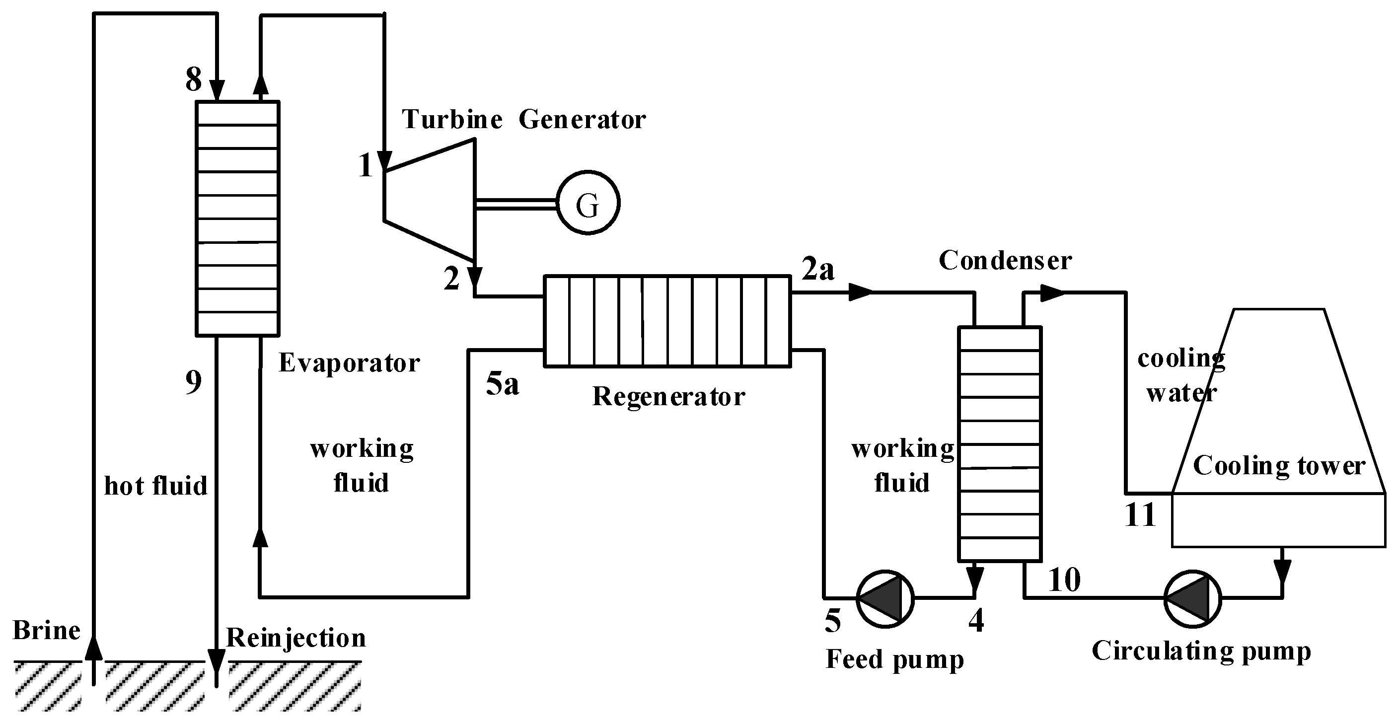
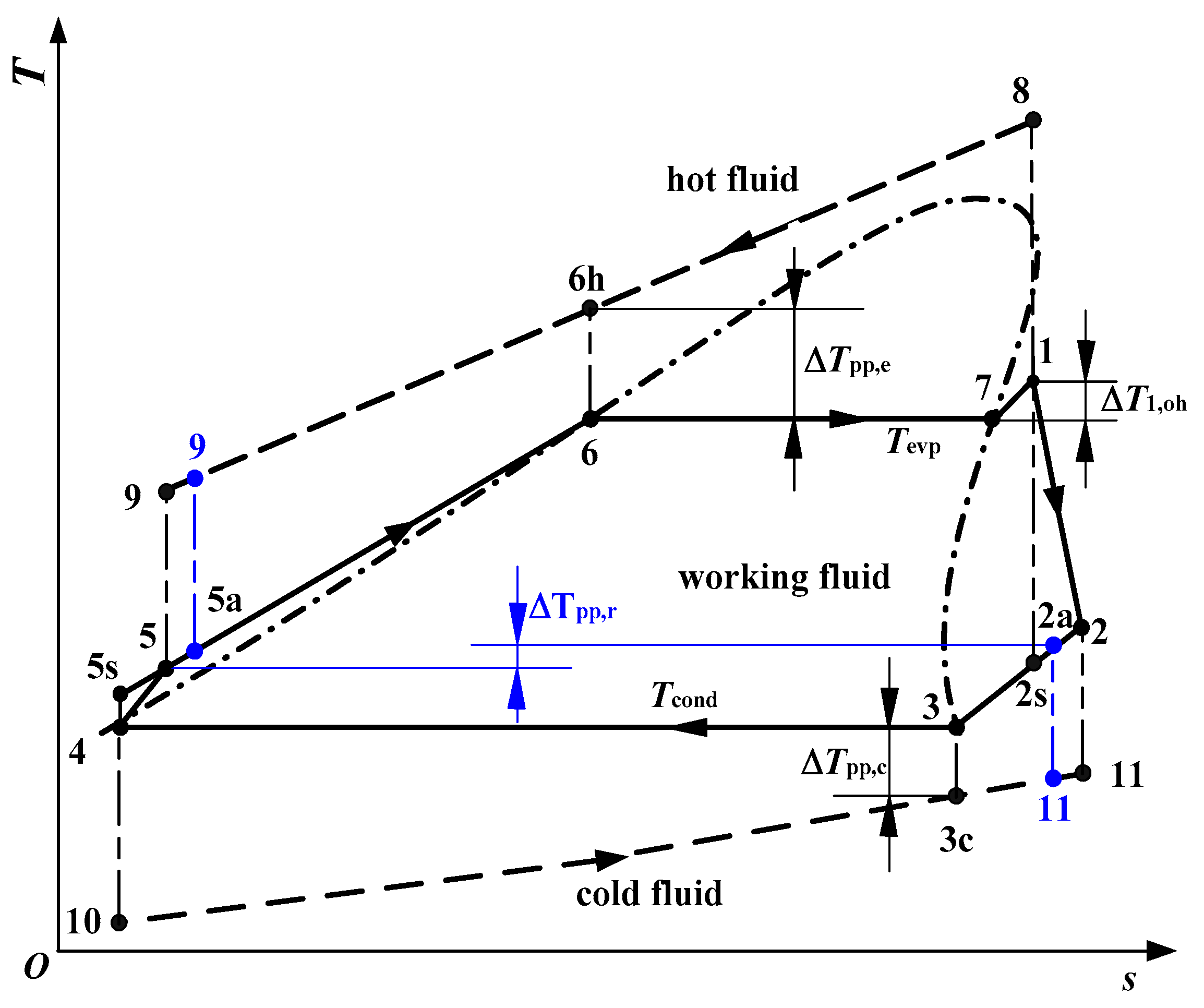
2. ORC System Modelling and Theoretical Analysis
3. ORC System Conditions and Constraints
4. Results and Discussions
4.1. Without Reinjection Temperature Limit
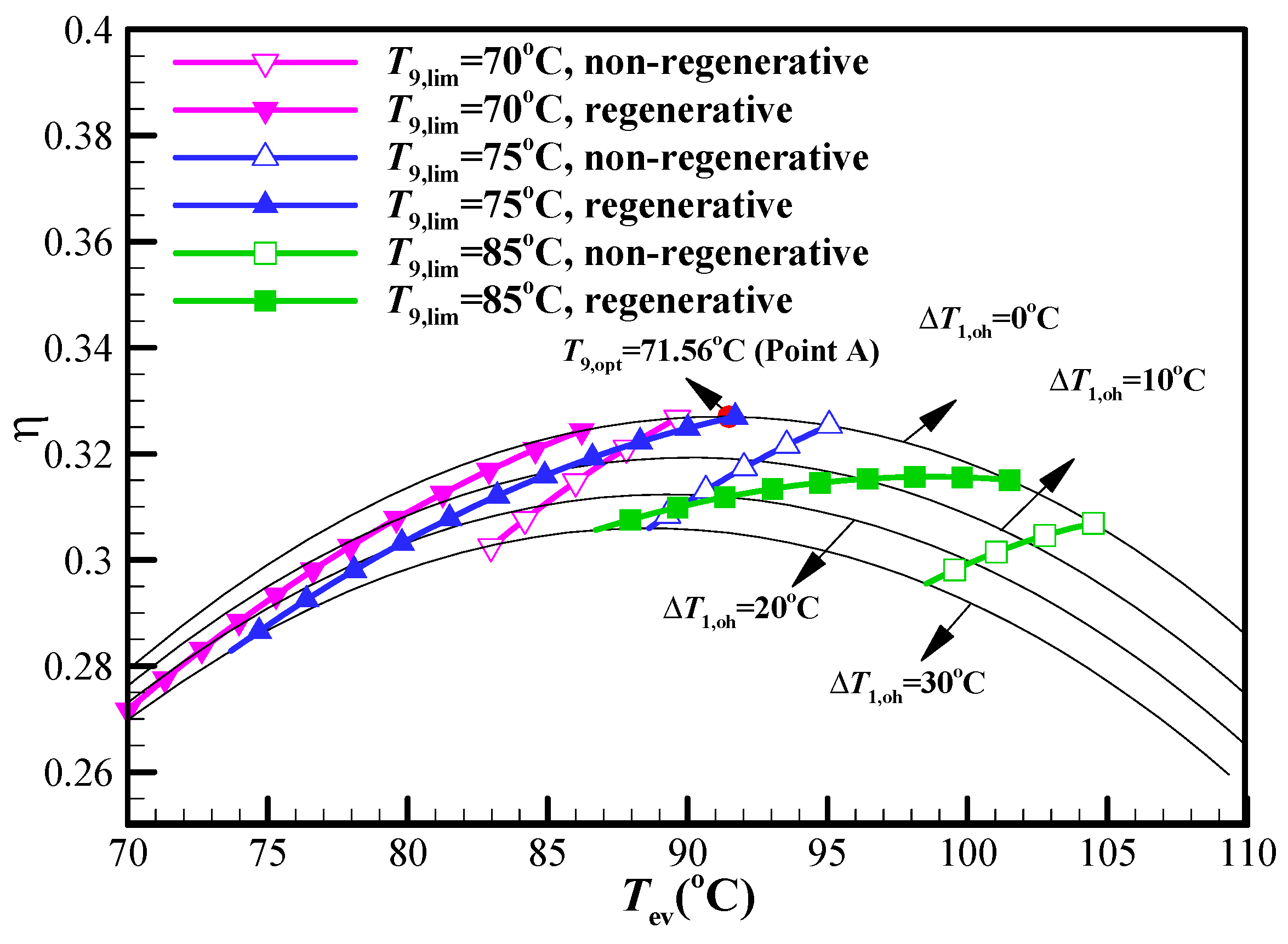
4.2. Considering Reinjection Temperature Limit
4.3. Optimal Results
5. Conclusions
- (1)
- A saturated non-regenerative cycle, saturated regenerative cycle, and superheated regenerative cycle are the most possible optimal cycle configurations. The optimal cycle configuration and the relevant working condition strongly depend on the value of reinjection temperature limit.
- (2)
- When the reinjection temperature limit exhibits influence on the system performance, the optimal plant exergy efficiency normally decreases with the increasing of reinjection temperature limit.
- (3)
- In the considered cases, with the assumed contains and hypothesis, working fluid isobutane always shows a higher plant exergy efficiency than other three working fluids without and with reinjection temperature limit.
Author Contributions
Funding
Conflicts of Interest
Abbreviations
| Abbreviations | |
| ORC | Organic Rankine Cycle |
| GWP | Global warming potential |
| sta-non | Saturated non-regenerative |
| sta-reg | Saturated non-regenerative |
| sup-reg | Superheated regenerative |
| Nomenclature | |
| cp | Specific heat capacity at constant pressure (J/(kg·K)) |
| h | Specific enthalpy (J/kg) |
| H | Pumping head for circulating pump (m) |
| m | Mass flow rate (kg/s) |
| p | Pressure (kPa) |
| s | Specific entropy (J/(kg·K)) |
| SP | Turbine size parameter (m) |
| T | Temperature (°C) |
| V | Volumetric flow rate (m3/s) |
| VR | Volumetric expansion ratio (-) |
| W | Power (W) |
| Subscripts | |
| 0 | Ambient condition |
| 1 | Turbine inlet |
| 2 | Turbine outlet |
| 2a | Regenerator outlet at low pressure |
| 2s | Turbine outlet with isentropic expansion |
| 3 | Saturated vapor state in condenser |
| 3c | Relevant point for cooling fluid in condenser at pinch point |
| 4 | Feed pump inlet |
| 5 | Feed ump outlet |
| 5a | Regenerator outlet at high pressure |
| 5s | Feed pump outlet with isentropic compression |
| 6 | Saturated liquid state in evaporator |
| 6h | Relevant point for hot fluid in evaporator at beginning evpaoration point |
| 7 | Saturated vapor state in evaporator |
| 8 | Hot fluid inlet |
| 9 | Hot fluid outlet |
| 10 | Cold fluid inlet |
| 11 | Cold fluid outlet |
| c | Condenser |
| cf | Cold fluid |
| cond | Condensing state |
| crit | Critical point |
| e | Evaporator |
| ev | Evaporating |
| hf | Hot fluid |
| g | Generator |
| lim | Reinjetion temperature limit |
| m | Transmission device |
| max | Maximum value |
| min | Minimum value |
| motor | motor for feed pump or circulating pump |
| net | net power output |
| opt | Optimal condition without reinjection temperature limit |
| p | Feed pump |
| pc | Circulating pump |
| pp | Pinch point |
| r | Regenerator |
| sta | Saturated state |
| sym | System |
| t | Turbine |
| wf | Working fluid |
| Greek symbols | |
| η | Efficiency (-) |
| Δh | Latent enthalpy (J/kg) |
| ΔT1,oh | Overheating degree at turbine inlet (°C) |
| ΔTpp | Pinch point temperature difference (°C) |
References
- Zarrouk, S.J.; Moon, H. Efficiency of geothermal power plants: A world review. Geothermics 2014, 51, 142–153. [Google Scholar] [CrossRef]
- Astofli, M.; Xodo, I.; Romano, M.C.; Macchi, E. Technical and economical analysis of a solar-geothermal hybrid plant based on an organic Rankine cycle. Geothermics 2011, 40, 58–68. [Google Scholar] [CrossRef]
- Tchanche, B.F.; Lambrinos, G.; Frangoudakis, A.; Papadakis, G. Low-grade heat conversion into power using organic Rankine cycles—A review of various applications. Renew. Sustain. Energy Rev. 2011, 15, 3963–3979. [Google Scholar] [CrossRef]
- Vignesh, P.; Suresh, S.; Grashin, C.J. Issues, comparsions, turbine selections and applications—An overview in organic Rankine cycle. Energy Convers. Manag. 2018, 166, 474–488. [Google Scholar] [CrossRef]
- Manente, G.; Lazzaretto, A.; Bonamico, E. Design guidelines for the choice between single and dual pressure layouts in organic Rankine cycle (ORC) systems. Energy 2017, 123, 413–431. [Google Scholar] [CrossRef]
- Li, T.L.; Hu, X.X.; Wang, J.Q.; Kong, X.F.; Liu, J.; Zhu, J.L. Performance improvement of two-stage serial organic Rankine cycle (TSORC) driven by dual-level heat sources of geothermal energy coupled with solar energy. Geothermics 2018, 76, 261–270. [Google Scholar] [CrossRef]
- Yari, M. Exergetic analysis of various types of geothermal power plants. Renew. Energy 2010, 35, 112–121. [Google Scholar] [CrossRef]
- Astolfi, M.; Diega, L.N.; Romano, M.C.; Merlo, U.; Filippini, S.; Macchi, E. Application of the novel “Emeritus” air cooled condenser in geothermal ORC. Energy Procedia 2017, 129, 479–486. [Google Scholar] [CrossRef]
- Maraver, D.; Royo, J.; Lemort, V.; Quoilin, S. Systematic optimization of subcritical and transcritical organic Rankine cyles (ORCs) constrained by technical parameters in multiple applications. Appl Energy 2014, 117, 11–29. [Google Scholar] [CrossRef]
- Javanshir, A.; Sarunac, N.; Razzaghpanah, Z. Thermodynamic analysis of a regenerative organic Rankine cycle using dry fluids. Appl. Therm. Eng. 2017, 123, 852–864. [Google Scholar] [CrossRef]
- Yamamoto, T.; Furuhata, T.; Arai, N.; Mori, K. Design and testing of the Organic Rankine Cycle. Energy 2001, 26, 239–251. [Google Scholar] [CrossRef]
- Saleh, B.; Koglbauer, G.; Wendland, M.; Fischer, J. Working fluids for low-temperature organic Rankine cycles. Energy 2007, 32, 1210–1221. [Google Scholar] [CrossRef]
- Dai, Y.P.; Wang, J.F.; Gao, L. Parametric optimization and comparative study of organic Rankine Cycle (ORC) for low grade waste heat recovery. Energy Convers. Manag. 2009, 50, 576–582. [Google Scholar] [CrossRef]
- Chagnon-Lessard, N.; Mathieu-Potvin, F.; Gosselin, L. Geothermal power plants with maximized specific power output: Optimal working fluid and operating conditions of subcritical and transcritical organic Rankine cycles. Geothermics 2016, 64, 111–124. [Google Scholar] [CrossRef]
- Walraven, D.; Laenen, B.; D’haeseleer, W. Comparison of thermodynamic cycles for power production from low-temperature geothermal heat sources. Energy Convers. Manag. 2013, 66, 220–233. [Google Scholar] [CrossRef]
- Astolfi, M.; Romano, M.C.; Bombarda, P.; Macchi, E. Binary ORC (Organic Rankine Cycles) power plants for the exploitation of medium-low temperature geothermal sources—Part A: Thermodynamic optimization. Energy 2014, 66, 423–434. [Google Scholar] [CrossRef]
- Clarke, J.; McLeskey, J.T., Jr. Multi-objective particle swarm optimization of binary geothermal power plants. Appl Energy 2015, 138, 302–314. [Google Scholar] [CrossRef]
- Chen, Q.C.; Xu, J.L.; Chen, H.X. A new design method for Organic Rankine Cycles with constraint of inlet and outlet carrier fluid temperatures coupling with the heat source. Appl. Energy 2012, 98, 562–573. [Google Scholar] [CrossRef]
- Borsukiewicz-Gozdur, A. Exergy analysis for maximizing power of organic Rankine cycle power plant driven by open type energy source. Energy 2013, 62, 73–81. [Google Scholar] [CrossRef]
- Diaz, A.R.; Kaya, E.; Zarrouk, S.J. Reinjection in geothermal fields—A worldwide review update. Renew. Sustain. Energy Rev. 2016, 53, 105–162. [Google Scholar] [CrossRef]
- Vivian, J.; Manente, G.; Lazzaretto, A. A general framework to select working fluid and configuration of ORCs for low-to-medium temperature heat sources. Appl Energy 2015, 156, 727–746. [Google Scholar] [CrossRef]
- Lazzaretto, A.; Manente, G. A new criterion to optimize ORC design performance using efficiency correlations for axial and radial turbines. Int. J. Thermodyn. 2014, 17, 173–181. [Google Scholar] [CrossRef]
- Song, J.; Gu, C.W.; Ren, X.D. Influence of the radial-inflow turbine efficiency prediction on the design and analysis of the Organic Rankine Cycle (ORC) system. Energy Convers. Manag. 2016, 123, 308–316. [Google Scholar] [CrossRef]
- Zhang, C.; Fu, J.L.; Kang, J.; Fu, W.C. Performance optimization of low-temperature geothermal organic Rankine cycles using axial turbine isentropic efficiency correlation. J. Braz. Soc. Mech. Sci. Eng. 2018, 40, 61. [Google Scholar] [CrossRef]
- Perdichizzi, A.; Lozza, G. Design criteria and efficiency prediction for radial inflow turbines. In Proceedings of the ASME 1987 International Gas Turbine Conference and Exhibition, Anaheim, CA, USA, 31 May–4 June 1987; Paper No. 87-GT-231. p. V001T01A086. [Google Scholar] [CrossRef]
- Le, V.L.; Kheiri, A.; Feidt, M.; Pelloux-Prayer, S. Thermodynamic and economic optimizations of a waste heat to power plant driven by a subcritical ORC (Organic Rankine Cycles) using pure or zeotropic working fluid. Energy 2014, 78, 622–638. [Google Scholar] [CrossRef]
- Satanphol, K.; Pridasawas, W.; Suphanit, B. A study on optimal comparison of zeotropic working fluid in an Organic Rankine Cycle (ORC) for low grade heat recovery. Energy 2017, 123, 326–339. [Google Scholar] [CrossRef]


| Parameter | Value |
|---|---|
| Geothermal brine temperature T8 (°C) | 150, 130 |
| Geothermal brine pressure p8 (kpa) | 1500 |
| Mass flow rate of geothermal brine mhf (kg/s) | 10, 20 |
| Evaporator pinch point temperature difference δtpp,e (°C) | 10 |
| Condenser pinch point temperature difference δtpp,c (°C) | 5 |
| Regenerator pinch point temperature difference δtpp,r (°C) | 5 |
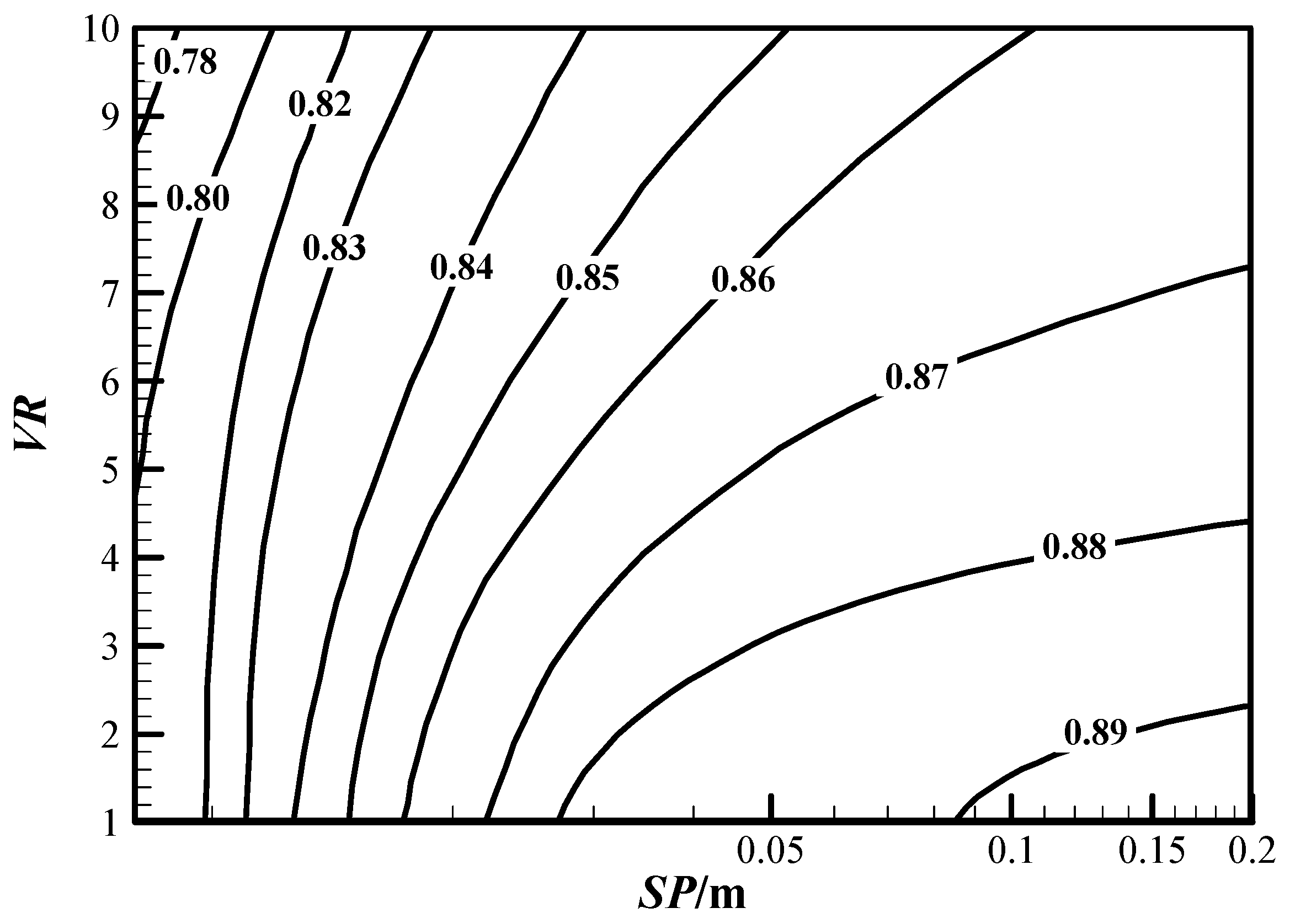
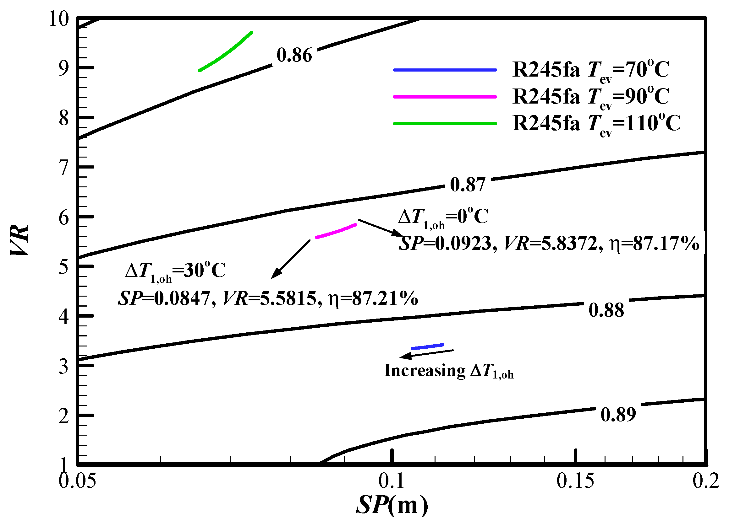
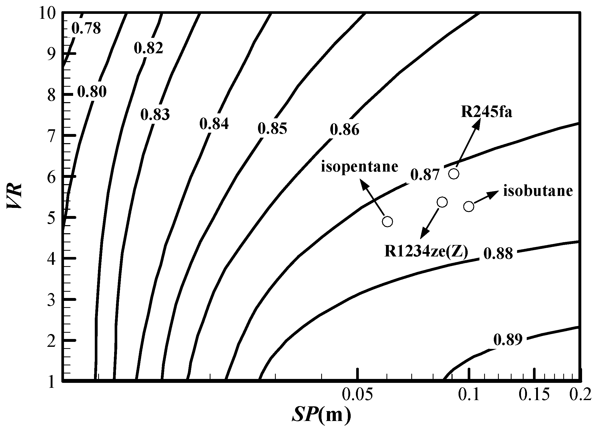
| Turbine efficiency ηt (-) | Turbine efficiency map in Figure 3 |
| Feed pump efficiency ηp (-) | 0.75 |
| Circulating pump efficiency ηpc (-) | 0.70 |
| Transmission efficiencyof turbine ηm (-) | 0.95 |
| Generator efficiency ηg (-) | 0.95 |
| Motor efficiency for feed pump ηp,motor (-) | Equation (13) |
| Motor efficiency for circulating pump ηpc,motor (-) | |
| Condensing temperature Tcond (°C) | 30 |
| Reinjection temperature limit T9,lim (°C) | 70, 75, 85 |
| Working Fluid | Tcrit (°C) | pcrit (kPa) | pcond (kPa) (Tcond = 30 °C) | Δhev (kJ) (Tev = 90 °C) | GWP (100 Years) |
|---|---|---|---|---|---|
| R245fa | 154.0 | 3651.0 | 177.8 | 143.92 | 1020 |
| R1234ze(Z) | 150.1 | 3533.0 | 210.2 | 155.01 | 7 |
| isopentane | 187.2 | 3378.0 | 109.2 | 286.33 | ~20 |
| isobutane | 134.7 | 3629.0 | 404.7 | 233.32 | 25 |
| Parameter | Reference Result | Present Result | Error (%) | Reference Result | Present Result | Error (%) |
|---|---|---|---|---|---|---|
| Fluid | R236fa | R245ca | ||||
| p1 (kPa) | 1700.00 | 1700.00 | 0.00 | 700.00 | 700.00 | 0.00 |
| T1 (K) | 367.95 | 367.95 | 0.00 | 363.55 | 363.50 | −0.01 |
| T2 (K) | 330.15 | 329.16 | −0.30 | 334.35 | 331.73 | −0.78 |
| T5 (K) | 318.05 | 317.75 | −0.09 | 317.55 | 317.39 | −0.05 |
| T9 (K) | 350.15 | 348.58 | −0.45 | 354.45 | 355.01 | 0.16 |
| mwf (kg/s) | 23.07 | 23.56 | 2.12 | 14.88 | 15.12 | 1.61 |
| Wnet (kW) | 335.23 | 331.73 | −1.04 | 303.15 | 300.56 | −0.85 |
| Working Fluid | Tev,opt (°C) | T9,opt (°C) | mwf,opt (kg/s) | ηt,opt (%) | ηopt (%) |
|---|---|---|---|---|---|
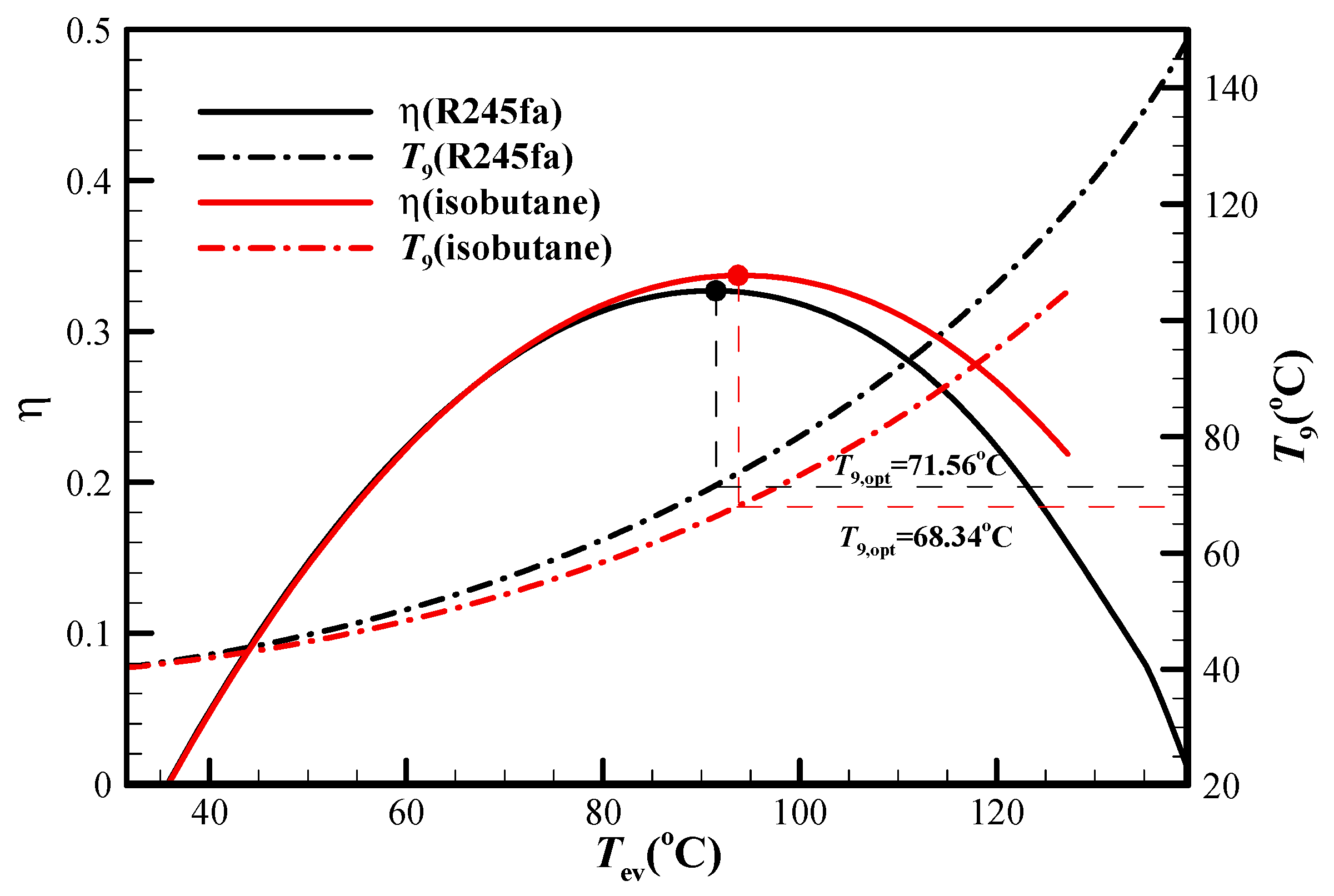
| R245fa | 91.40 | 71.56 | 14.47 | 87.08 | 32.70 |
| R1234ze(Z) | 90.95 | 73.84 | 13.54 | 87.28 | 32.13 |
| isopentane | 89.44 | 73.35 | 7.49 | 87.44 | 31.89 |
| isobutane | 94.07 | 68.34 | 8.70 | 87.22 | 33.71 |
| Working Fluid | T9,lim (°C) | Optimal Cycle | Tev (°C) | ΔT1,oh (°C) | T9 (°C) | mwf (kg/s) | ηt (%) | η (%) |
|---|---|---|---|---|---|---|---|---|
| R245fa | 70 | sta-non | 91.40 | 0 | 71.56 | 14.47 | 87.08 | 32.698 |
| 75 | sta-reg | 91.71 | 0 | 75 | 14.43 | 87.06 | 32.696 | |
| 85 | sup-reg | 98.96 | 4.65 | 85 | 12.34 | 86.62 | 31.57 | |
| R1234ze(Z) | 70 | sta-non | 90.95 | 0 | 73.84 | 13.54 | 87.28 | 32.13 |
| 75 | sta-reg | 91.82 | 0 | 75 | 13.38 | 87.23 | 32.12 | |
| 85 | sup-reg | 94.70 | 14.44 | 85 | 11.44 | 87.08 | 31.29 | |
| isopentane | 70 | sta-non | 89.44 | 0 | 73.35 | 7.49 | 87.44 | 31.89 |
| 75 | sta-reg | 89.44 | 0 | 78.83 | 7.49 | 87.44 | 31.89 | |
| 85 | sta-reg | 95.33 | 0 | 85 | 6.78 | 87.11 | 31.50 | |
| isobutane | 70 | sta-reg | 94.13 | 0 | 71.54 | 8.69 | 87.21 | 33.71 |
| 75 | sta-reg | 98.22 | 0 | 75 | 8.27 | 86.93 | 33.54 | |
| 85 | sup-reg | 100.93 | 9.24 | 85 | 7.08 | 86.79 | 31.87 |
| Working Fluid | T9,lim (°C) | Optimal Cycle | Tev (°C) | ΔT1,oh (°C) | T9 (°C) | mwf (kg/s) | ηt (%) | η (%) |
|---|---|---|---|---|---|---|---|---|
| R245fa | 70 | sta-non | 91.40 | 0 | 71.56 | 28.98 | 87.24 | 32.899 |
| 75 | sta-reg | 91.73 | 0 | 75 | 28.86 | 87.23 | 32.898 | |
| 85 | sup-reg | 99.34 | 4.01 | 85 | 24.66 | 86.87 | 31.80 | |
| R1234ze(Z) | 70 | sta-non | 91.15 | 0 | 74.01 | 27.01 | 87.43 | 32.323 |
| 75 | sta-reg | 91.84 | 0 | 75 | 26.76 | 87.39 | 32.322 | |
| 85 | sup-reg | 94.74 | 14.42 | 85 | 22.87 | 87.28 | 31.49 | |
| isopentane | 70 | sta-non | 89.55 | 0 | 73.46 | 14.96 | 87.53 | 32.04 |
| 75 | sta-reg | 89.55 | 0 | 79.01 | 14.96 | 87.53 | 32.04 | |
| 85 | sta-reg | 95.35 | 0 | 85 | 13.56 | 87.26 | 31.67 | |
| isobutane | 70 | sta-reg | 94.31 | 0 | 71.65 | 17.35 | 87.47 | 34.01 |
| 75 | sta-reg | 98.26 | 0 | 75 | 16.52 | 87.24 | 33.85 | |
| 85 | sup-reg | 100.65 | 9.68 | 85 | 14.16 | 87.15 | 32.17 |
| Working Fluid | T9,lim (°C) | Optimal Cycle | Tev (°C) | ΔT1,oh (°C) | T9 (°C) | mwf (kg/s) | ηt (%) | η (%) |
|---|---|---|---|---|---|---|---|---|
| R245fa | 70 | sta-non | 79.15 | 0 | 70.81 | 11.27 | 87.73 | 27.98 |
| 75 | sta-reg | 81.68 | 0 | 75 | 10.72 | 87.57 | 27.89 | |
| 85 | sup-reg | 83.94 | 23.18 | 85 | 8.63 | 87.44 | 26.45 | |
| R1234ze(Z) | 70 | sta-non | 79.00 | 0 | 72.43 | 10.46 | 87.89 | 27.54 |
| 75 | sup-reg | 80.42 | 3.23 | 75 | 9.94 | 87.81 | 27.46 | |
| 85 | sup-reg | 82.71 | 30 | 85 | 7.99 | 87.69 | 26.61 | |
| isopentane | 70 | sta-non | 78.54 | 0 | 72.05 | 5.87 | 87.96 | 27.61 |
| 75 | sta-reg | 78.54 | 0 | 75.22 | 5.87 | 87.96 | 27.61 | |
| 85 | sup-reg | 87.25 | 1.32 | 85 | 4.74 | 87.44 | 26.33 | |
| isobutane | 70 | sta-reg | 80.22 | 0 | 70.95 | 6.67 | 87.88 | 28.27 |
| 75 | sta-reg | 84.33 | 0 | 75 | 6.17 | 87.61 | 28.01 | |
| 85 | sup-reg | 84.80 | 23.01 | 85 | 4.97 | 87.59 | 26.38 |
© 2018 by the authors. Licensee MDPI, Basel, Switzerland. This article is an open access article distributed under the terms and conditions of the Creative Commons Attribution (CC BY) license (http://creativecommons.org/licenses/by/4.0/).
Share and Cite
Zhang, C.; Fu, J.; Yuan, P.; Liu, J. Guidelines for Optimal Selection of Subcritical Low-Temperature Geothermal Organic Rankine Cycle Configuration Considering Reinjection Temperature Limits. Energies 2018, 11, 2878. https://doi.org/10.3390/en11112878
Zhang C, Fu J, Yuan P, Liu J. Guidelines for Optimal Selection of Subcritical Low-Temperature Geothermal Organic Rankine Cycle Configuration Considering Reinjection Temperature Limits. Energies. 2018; 11(11):2878. https://doi.org/10.3390/en11112878
Chicago/Turabian StyleZhang, Chao, Jinglun Fu, Pengfei Yuan, and Jianjun Liu. 2018. "Guidelines for Optimal Selection of Subcritical Low-Temperature Geothermal Organic Rankine Cycle Configuration Considering Reinjection Temperature Limits" Energies 11, no. 11: 2878. https://doi.org/10.3390/en11112878