A Mechanical Model of Gas Drainage Borehole Clogging under Confining Pressure and Its Application


1
School of Energy Science and Engineering, Henan Polytechnic University, Jiaozuo 454000, Henan, China
2
School of Safety Engineering, China University of Mining and Technology, Xuzhou 221116, Jiangsu, China
3
Collaborative Innovation Center of Coal Work Safety, Jiaozuo 454000, Henan, China
*
Authors to whom correspondence should be addressed.
Energies 2018, 11(10), 2817; https://doi.org/10.3390/en11102817
Submission received: 21 September 2018
/
Revised: 7 October 2018
/
Accepted: 16 October 2018
/
Published: 18 October 2018
Abstract
:Drilling in a coal seam that has gas and coal outburst activities is closely related to the discharge of drill cuttings into a borehole. Due to the low effectiveness of slagging, there is a risk that the drilling equipment will be lost if the borehole contains too many drill cuttings, especially when drilling in soft coal seams that suffer from borehole deformation and instability problems. In order to investigate the mechanisms underlying clogged boreholes, a mechanical model is established that considers the confining pressure pi that surrounds a borehole. The characteristics of clogged boreholes, which are affected by parameters such as the clogging segment’s length L, the drilling angle θ and confining pressure pi, were analyzed. The results show that the dredging pressure has nearly exponential growth as the clogging segment’s length L increases and the gravity of the clogging segment reduces the demand for dredging pressure, especially in upward drilling. In downward drilling, the blowing-through pressure increases as the absolute value of the drilling angle increases and will reach a maximum value when the drilling angle θD is in the range of −π/2~0. At the same time, the borehole’s confining pressure pi is the dominant factor in borehole clogging. Meanwhile, boreholes with a high confining pressure pi, especially in soft coal seams and coal seams with a coal outburst, constitute a significant risk. Finally, an actual drilling field construction was evaluated and optimized by applying the clogging segment mechanical model. The results show that the drilling depth was improved by 18.5% on average, and the drilling efficiency was improved by 39.7%, in comparison to drilling activities without optimization.
1. Introduction
Coal-bed gas (CBM) refers to the absorbed and the free methane gas in a coal bed. In coal mining, methane is a harmful gas and is responsible for most cases of mining disaster that involve gas [1]. As an energy resource, methane is a kind of clean energy and can be used in civilian or industrial gas applications [2]. In the context of environmental protection, a low concentration of methane, when emitted into the atmosphere, can increase the greenhouse effect; the results of analyses on global warming potential (GWP) suggest that the greenhouse effect of methane (CH4) is 25 times greater than that of carbon dioxide (CO2) [3,4]. Therefore, gas drainage and utilization in methane-rich coal seams has significance for, among other things, safety, energy saving and environmental protection. [5,6]. The tendency in coal mining has been to develop deeper underground, where coal seams have the “three high and two low” characteristic; namely, high geostress, high gas content, high gas pressure, low strength and low permeability [7,8]. The coal seam permeability is less than 0.1 md in many mining areas, which has led to long gas drainage cycles, low gas drainage efficiencies, high material losses and indirect delays in coal seam mining progress and has brought about great economic losses for the coal mining industry [9,10]. Protective coal seams mining and relief-pressure gas drainage are the main methods for controlling the occurrence of disasters that involve gas. For a single coal seam with a coal and gas outburst that does not have protective coal seams, the gas is pre-drained by drilling a borehole down and across the seam [5]. Ground-well drainage has been applied in a coal and gas outburst mine under complicated geological conditions and the investment cost was found to be high and the drainage effect not ideal [11]. In 2015, the total CBM production was 18 billion cubic meters, of which the ground-well drainage production was only 4.4 billion cubic meters and the underground gas drainage volume was 13.6 billion cubic meters. Therefore, gas drainage in coal mines has become a combination of underground gas drainage and ground-well drainage [12].
Boreholes are the premise of gas drainage in underground mines [13,14]. The quantity of material removed during a borehole’s construction is huge in coal seams with a coal outburst, and, in many regional boreholes’ construction, the quantity of material that was removed was more than 0.3 m/t (the length of the constructed borehole for every ton of coal mined). Coal seams with an outburst of coal give priority to class III crushed coal (Protodyakonov coefficient f = 0.25~0.5) and class IV mylonite coal (Protodyakonov coefficient f < 0.3) [15]. In the process of drilling a borehole, significant deformation in the borehole’s wall can occur and it can easily collapse to form a “drilling cave” [16,17] that is caused by the ground stress, gas pressure and tectonic stress. When, in the discharge of the drilling operation, there is a space shrinkage, the resistance to movement of the drill cuttings will increase and the cuttings can easily accumulate to form a clogging segment of a certain length. If the borehole’s internal fluid pressure reaches the system’s air pressure maximum and the clogging segment is not dredged, then the drilling operation will not be able to continue [18]. Due to the low strength of soft coal, a rheological phenomenon appears around the borehole in the process of drilling. Therefore, the confining pressure pi is formed between the clogging segment and the borehole’s wall. Considering the confining pressure pi in the analysis means that it will more closely reflect actual working conditions. In this paper, we analyze the mechanical characteristics of clogging segments in gas drainage boreholes under the confining pressure. Then, a mechanical model of clogging segments is used to evaluate and optimize a drilling field construction.
2. Objective of the Study
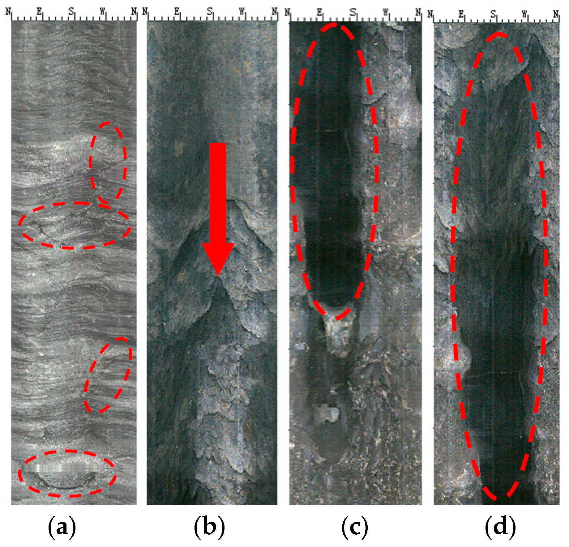
Through the observation of a borehole at a mine site using a borescope, the borehole is shown to have different features in different positions that indicate failure. As shown in Figure 1a, the borehole’s wall is intact and only a few irregular fissures can be observed. As shown in Figure 1b, a transition area with more damage can be observed along the direction of the red arrow, where the destroyed space extends deeply down the borehole’s wall. As shown in Figure 1c,d, the damage to borehole’s wall is serious and obvious spalling-holes can be observed.
For a drilling operation with an air power discharge, the deformation and destruction of the borehole lead to the shrinkage of the discharge space, resulting in an increase in the drill cuttings’ movement resistance and a pressure loss in the air system. The drill cuttings will accumulate as a result of factors such as shrinkage in the borehole’s wall, unstable air pressure and large blocks of coal. However, a clog will form if the abovementioned factors cannot be kept under control, as shown in Figure 2. The clogging segment L is formed by large particles of coal and rock. When the discharge power reaches the maximum pressure Pmax of the air system, there is no way to dredge the clogging segment and the drilling operation will terminate. Therefore, the formation of clogging segments in boreholes is an important reason for why it is difficult to drill in soft coal seams. The objectives of this study include:
- (1)
- Establishing a clogging segment under confining pressure mechanics model that can be used to analyze the influence of a borehole’s parameters on a borehole clog.
- (2)
- Evaluating the improvement in a drilling scheme using the clogging segment mechanics model.
3. Clogging Segment Mechanics Model
As shown in Figure 3, once a clogging segment has formed in a borehole, the borehole’s wall will show an obvious rheological phenomenon under the geostress, tectonic stress and gas pressure. Then, the coal around borehole’s wall will continue to be deformed. When the deformation becomes evident, the borehole’s wall will squeeze the clogging segment. As a result, the additional force pi will form in the interface between the clogging segment and the borehole’s wall.
As shown in Figure 3, once the clogging segment has formed, a frictional resistance appears around the clogging segment under a combination of the air pressure p and the confining pressure pi, the properties of which are as follows:
- (1)
- The frictional resistance is formed by the coal cinder gravity of the clogging segment.
- (2)
- Lateral pressure is formed on the two contact surfaces of the clogging segment according to the air pressure p, which includes the lateral pressure pc1 between the surface of the clogging segment and the drill pipe’s outside surface and the lateral pressure pc2 between the surface of the clogging segment and that of the borehole’s wall.
- (3)
- The formation of frictional resistance also depends partly on the confining pressure pi.
According to the conditions of the drilling process, a mechanics model of the corresponding clogging segments in boreholes is established. The borehole’s angle ranges from −π/2 to π/2, the upward borehole’s angle ranges from 0 to π/2, the horizontal borehole’s angle is equal to 0 and the downward borehole’s angle ranges from −π/2 to 0.
Figure 4 shows the mechanical model of a clogging segment in an upward borehole, according to the stress state of the clogging segment, where L is the clogging segment’s length, θ is the borehole’s angle, D is the borehole’s diameter and d is the drill pipe’s diameter. The air pressure in the clogging segment is denoted as p1. The air pressure outside the clogging segment (atmospheric pressure) is denoted as p2. The confining pressure around the borehole is denoted pi. As the borehole deformation mechanism is very complex, some simplifications and assumptions are introduced, as follows:
- (1)
- The cross-section of boreholes is circular.
- (2)
- The medial axis of the drill pipe coincides with that of the borehole, regardless of the bending of the drill pipe in the borehole.
Once a clogging segment is formed, the lateral pressure pc1 appears on the interface between the drill pipe and the clogging segment under the effect of the air pressure p1 and the lateral pressure pc2 is formed on the interface between the clogging segment and the borehole’s wall.
3.1 Stress Analysis of a Clogging Segment
(1) The frictional resistance caused by gravity
The frictional resistance caused by gravity has two main parts, as shown in Figure 4. One part is the gravity induced by the cuttings in the space between the blue dotted lines. The other part is the gravity induced by the cuttings other than those in the space mentioned. Setting an infinitesimal length for the drilling segment dL, F1 is the total friction resistance caused by gravity. So, the equation for the frictional resistance F1 caused by gravity can be expressed as:
where Sr is the cross-sectional area of coal cuttings around the drill pipe, Sd is the dotted line area above the drill pipe, L is the length of the clogging segment, ρb is the density of the accumulated coal in the clog, f1 is the friction factor between the clogging segment and the surface of the drill pipe and f2 is the friction factor between the clogging segment and borehole’s wall.
(2) The frictional resistance caused by lateral pressure
As shown in Figure 4, after a clogging segment is formed, the lateral pressure pc1 and the lateral pressure pc2 appear where the clogging segment interfaces with the drill pipe and the borehole’s wall under the effect of the axial air pressure p1. So, the equation for the frictional resistance F2 caused by lateral pressure can be expressed as:
where p is the axial air pressure around the clogging segment in the borehole, k is the lateral pressure coefficient and D is the diameter of the borehole.
(3) The frictional resistance caused by the confining pressure pi
As shown in Figure 4, the frictional resistance F3 is formed by the confining pressure pi on the interface between the drill pipe and the clogging segment. The equation for the frictional resistance F3 caused by the confining pressure pi can be expressed as:
3.2. Equation for the Mechanics of a Clogging Segment
Based on Equations (1)–(3) and according to the stress analysis of the clogging segment, a load balance equation is established with a clogging segment as the research object:
where,
where,
For the same construction site, once the drilling design scheme has been selected, the parameters D, d, ρb, f, θ, and k are seen as constants. Most of the time, the confining pressure pi does not change much around a clogging segment in a borehole during its construction. At the same time, regardless of the increase in the confining pressure pi that is caused by creeping coal, the boundary conditions will be such that p equals to p2 when L is 0 and when the clogging segment length is L, p = p1, namely:
When a clogging segment is formed, the air pressure p2 outside the clogging segment is the same as the atmospheric pressure. Taking the atmospheric pressure as the referential parameter (p2 = 0), the air pressure p1 inside the clogging segment is determined by the compressed air system for discharging drill cuttings. Therefore, Equation (9) can be expressed as:
Based on Equation (11), the borehole dredging pressure p can be expressed as:
3.3. The Critical Length of a Clogging Segment
Based on Equation (12), the corresponding dredging pressure p has a positive correlation with the length of the clogging segment, L. When the dredging pressure reaches its maximum, Pmax, the critical length of the clogging segment, L0, can be obtained. In other words, the clogging segment cannot be dredged once the value of L is larger than that of the clogging segment’s critical length L0. Based on Equation (12), the critical length of a clogging segment, L0, can be expressed as:
4. The Influence of the Borehole’s Parameters on Borehole Clogging
4.1. The Method of Analysis and Basic Parameters
4.1.1. The Method of Analysis
Based on Equation (12), the equation that models a clogging segment involves important parameters in drilling construction, such as the borehole’s diameter D, the drill pipe’s diameter d, the accumulation density of drill cuttings ρb, the friction factor f1 between the coal clogging segment and the drill pipe’s surface, the friction factor f2 between the coal clogging segment and the borehole’s wall, the drilling construction angle θ and the lateral pressure coefficient k.
At the same time, the confining pressure pi on the clogging segment induced by borehole shrinkage was also considered in the model. Therefore, based on Equation (12), the influence of the above parameters on borehole clogging can be analyzed. In this paper, our analysis is focused on the borehole’s angle θ and the confining pressure pi.
4.1.2. Basic Parameters
(1) The accumulation density, ρb
The accumulation density of drill cuttings depends mainly on the kind of coal. For example, the accumulation density of anthracite varies from 700 to 1000 kg/m3, the accumulation density of bituminous coal varies from 800 to 1000 kg/m3, the accumulation density of lignite varies from 600 to 800 kg/m3 and the accumulation density of peat varies from 290 to 500 kg/m3. Considering the compaction effect of drill cuttings on coal, the accumulation density of coal will increase but it generally will not exceed the coal tamping density [19,20]. The coal tamping density is generally in the range of 900 to 1200 kg/m3. Therefore, the average coal accumulation density ρb ranges from 600 to 1100 kg/m3.
(2) The lateral pressure coefficient, k
The ratio of radial stress to axial pressure is known as the lateral pressure coefficient k. When a borehole is clogged, radial stress is generated from a combination of the axial air pressure and the gravity of the clogging segment. Ideally, the lateral pressure coefficient k would be determined using the internal friction angle of the drill cutting particles, also known as the active Rankine coefficient [21]. The formula for calculating the lateral pressure coefficient can be expressed as:
Based on experimental research, Xie Benming et al. [22] found the lateral pressure coefficient value that was calculated using the Rankine coefficient to be less than the actual value. They modified Equation (14) as follows:
According to the coal’s type and granularity, the internal friction angle of coal commonly ranges from 25° to 35°, while the lateral pressure coefficient k ranges from 0.4 to 0.7.
(3) The frictional coefficient f
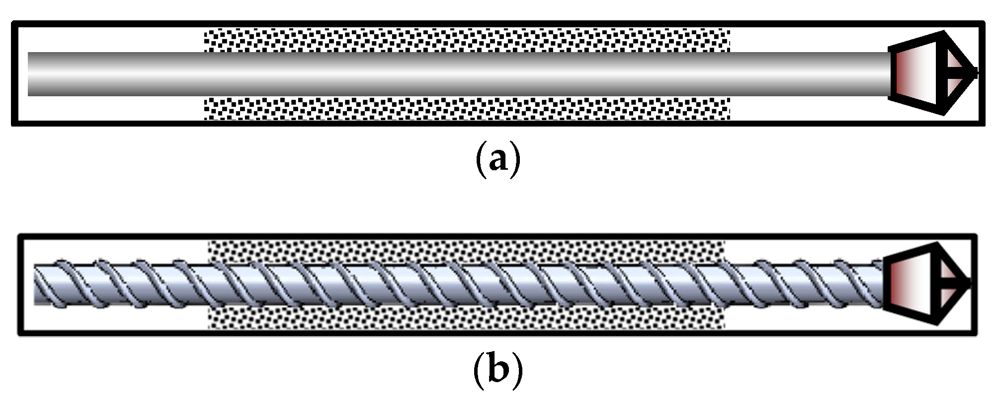
The frictional coefficient comprises the friction factor f1 between the coal clogging segment and the surface of the drill pipe and the friction factor f2 between the coal clogging segment and the borehole’s wall. The friction factor f1 mainly depends on the type of drill pipe, as shown in Figure 5. When using a circular pipe, the friction coefficient will be smaller and f1 may vary from 0.1 to 0.2. When using a spiral-ribbed drill pipe, the friction coefficient’s range will be higher: up to 0.3~0.5. Meanwhile, the friction factor f2 between the clogging segment and the borehole’s wall mainly depends on the situation of the borehole’s wall, which is generally in the range of 0.2~0.6. However, the friction factor f2 shows an obvious increasing trend when the borehole’s wall is destroyed.
(4) The borehole and drill pipe diameters
The diameter of a drill pipe is typically ⌀63.5 mm, ⌀73 mm, or ⌀89 mm, while those of the drill bits that are equipped by Polycrystalline Diamond Compacts are ⌀89 mm, ⌀94 mm, ⌀113 mm and ⌀133 mm for middle–hard coal seams [23]. At the same time, alloyed drill bits with diameters of ⌀120 mm, ⌀130 mm and ⌀153 mm are used for soft coal and soft rock. In field drilling construction, the value of the borehole’s diameter will be decreased due to borehole shrinkage and disturbances to the drill pipe. As a result, the diameter of a borehole is smaller than that of the drill bit in zones with serious borehole wall shrinkage, while the opposite situation obtains in zones with borehole wall expansion. On average, the diameter D of a borehole ranges from 90 mm to 160 mm.
4.2. The Relationship between the Dredging Pressure p and the Length of the Clogging Segment L
Assuming that the borehole’s diameter D is 120 mm, the drill pipe’s diameter d is 73 mm, the friction factor f1 is 0.1, the friction factor f2 is 0.3, the lateral pressure coefficient k is 0.5, the coal accumulation density ρb is 800 kg/m3 and the confining pressure pi is 0 Pa, the dredging pressure p can be expressed as the corresponding equations that are based on Equation (12). When θ equals 5°, the borehole’s dredging pressure p can be expressed as:
When θ equals −5°, the borehole’s dredging pressure p can be expressed as:
Based on Equations (16) and (17), the relationship of fit between the dredging pressure p and the clogging segment’s length L is as shown in Figure 6.
Based on an analysis of Figure 6, the following conclusions can be drawn:
- (1)
- The dredging pressure is not sensitive to the clogging segment’s length when it is less than 0.6 m. However, it shows a dramatic increase with the growth of the length of the clogging segment when it is greater than 0.6 m. Once L increases to 1.0 m, the corresponding dredging pressure is more than 1.2 MPa, which will be a significant burden on a compressed-air pipe system underground. So, it will be difficult to efficiently drill the borehole if the clogging segment is not dredged in time when the clogging segment’s length is under 1.0 m with an angle of 5°.
- (2)
- For the downward borehole’s construction, the corresponding pink curve lies to the left of the blue curve, which shows that the demand for dredging pressure for the downward borehole is much larger than that for the upward borehole when dredging a clogging segment of the same length. So, upward boreholes should be given high priority in actual engineering operations.
4.3. The Influence of the Borehole’s Angle on Borehole Clogging
Setting the length of the clogging segment to be L = 0.6 m, while keeping the other parameters the same as in the preceding section, the dredging pressure p can be expressed as the corresponding equations that are based on Equation (12). When pi equals 0 Pa, the borehole’s dredging pressure p can be expressed as:
When pi equals 1000 Pa, the borehole’s dredging pressure p can be expressed as:
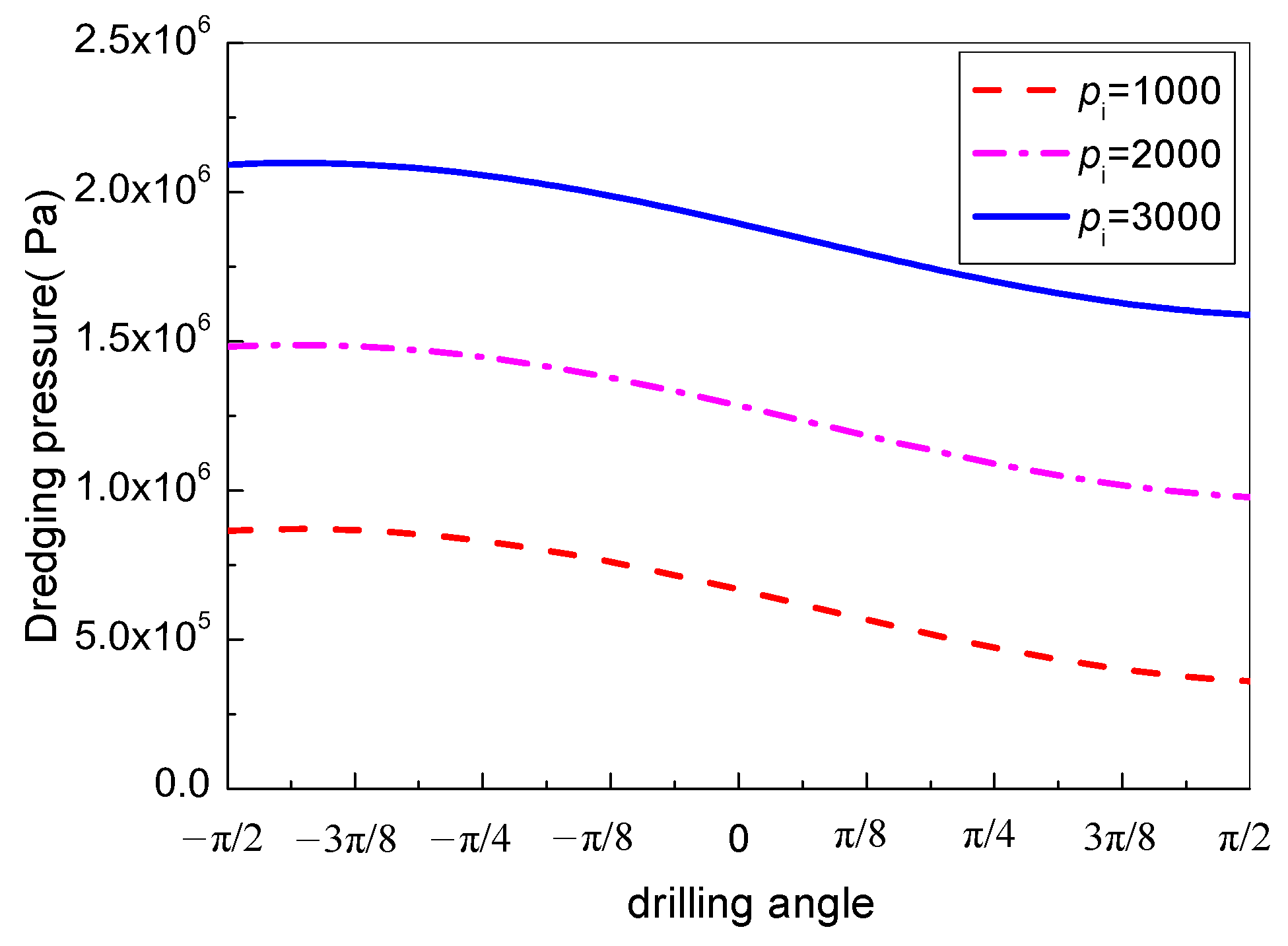
Based on Equations (18) and (19), the relationship of fit between the dredging pressure p and the borehole’s angle is as shown in Figure 7.
Based on an analysis of Figure 7, the following conclusions can be drawn:
- (1)
- For the upward borehole’s construction, the dredging pressure falls rapidly as the borehole’s angle increases from 0 to π/2. For pi = 0 Pa, the dredging pressure reaches 0 Pa when the corresponding borehole angle is 12.3°. So, the clogging segment could be dredged by gravity without the need for air pressure when the angle is over 12.3°. For pi = 1000 Pa, affected by the confining pressure, the minimum dredging pressure falls to A0 (π/2, 3.61 × 10⁵), which means that the minimum dredging pressure is 0.361 MPa when θ is π/2. So, the confining pressure plays a negative role in the dredging of drill cuttings.
- (2)
- For the construction of the horizontal borehole, the intersection points of the corresponding dredging pressure with the virtual axis along the two lines (pi = 0 Pa, pi = 1000 Pa) are B (0, 5.47 × 10⁴) and B0 (0, 6.67 × 10⁵), respectively. The maximum dredging pressure of the clogging segment is 0.667 MPa and the air pressure in the majority of the pipeline is greater than the maximum dredging pressure. Therefore, for the construction of the horizontal borehole under such conditions, the clogging segment in the borehole could be dredged easily if it does not grow.
- (3)
- For the construction of the downward borehole with the angle range of −π/2~0, the dredging pressure reaches its maximum at D (−1.357, 2.57 × 10⁵) and D0 (−1.357, 8.7 × 10⁵) along the two lines, respectively. So, it can be concluded that the corresponding dredging pressure will increase as the borehole’s angle increases from −π/2 to −77.7°. However, it will decrease as the borehole’s angle increases from −77.7° to 0°.
4.4. The Influence of the Confining Pressure on Borehole Clogging
Based on the influence of the borehole’s angle θ to borehole clogging, the confining pressure around the clogging segment plays a leading role in the growth of the borehole’s dredging pressure. In order to analyze the influence of the confining pressure around a clogging segment on the clogging segment, the confining pressure pi was set at 1000 Pa, 2000 Pa and 3000 Pa and the other parameters were kept the same as in the preceding section. When pi equals 1000 Pa, the dredging pressure p can be expressed as the corresponding equations that are based on Equation (12):
When pi equals 2000 Pa, the borehole dredging pressure p can be expressed as:
When pi equals 3000 Pa, the borehole dredging pressure p can be expressed as:
Based on Equations (20)–(22), the curves fitting the relationship between the borehole’s angle θ and the dredging pressure p under different confining pressures are shown in Figure 8. As the confining pressure pi increases (pi = 1000 Pa, pi = 2000 Pa, pi = 3000 Pa), the corresponding curve moves upward along the longitudinal axis and the amount of increase in the corresponding dredging pressures is 6.13 × 10⁵ Pa, 1.23 × 10⁵ Pa and 1.84 × 10⁵ Pa, respectively. Indeed, the minimum value of dredging pressure is more than 1.0 MPa when pi = 2000 Pa. It would be difficult for some of China’s pipelines to meet this requirement. Additionally, there is a high risk of borehole clogging for those coal mines that have soft coal seams.
In order to address the difficulties with drilling in soft coal seams, drill rigs with high power and high torque have been introduced but little success has been reported. As mentioned above, in the process of drilling, when clogging occurs in a borehole with a certain confining pressure in the clogging segment, it will be difficult to dredge, which will force the drilling operation to terminate. Visibly, after a clogging segment has formed, a certain confining pressure pi is formed between the clogging segment and the borehole’s wall due to the effect of the ground stress, the gas pressure, the tectonic stress and the rheological phenomenon for coal. The formation of the confining pressure pi is one of the important factors that causes further difficulty in dredging clogging segments in boreholes.
5. The Engineering Application
5.1. The Method for Evaluating the Drilling Scheme
The flow diagram for the mechanical model of borehole clogging in the engineering application is shown in Figure 9.
The Bai Ping coal mine is located in the east of Dengfeng City, Henan Province, China. The construction site is at the 21,001 working face, 320 m away from the stopping line. The depth of the coal seam is 450 m on average, the coal seam’s sturdiness coefficient is 0.15 and the primitive gas content is 5.5 m3/t. The thickness of the coal seam varies from 0 to 18.88 m. Many drilling accidents have been recorded, such as drill pipe sticking, breaks in drill pipes and loss of drill pipes. Because of the frequent changes in the coal seam’s thickness, it is easy to bend a drill’s path into roof or floor rocks with an actual depth of only 30 to 50 m, which is far below the designed value.
5.2. Optimization of the Drilling Scheme
5.2.1. Analysis of the Mine’s Current Drilling Process
At present, a ZDY3200 drill rig with a ⌀73 mm × 1 m round drill pipe and a ⌀94 mm three-wing carbide drill bit is being applied in the Bai Ping mine. Based on the theory of fluid dynamics, the hydraulic diameter can be calculated by dH = D − d = 94 mm − 73 mm = 21 mm and the width of the annular space for discharge is only 10.5 mm. The basic parameters of the drilling technology are shown in Table 1.
The dredging pressure p can be expressed as the corresponding equations that are based on Equation (12)
Based on Equation (23), the curve fitting the relation between the dredging pressure p and the clogging segment’s length L is shown in Figure 10.
The highest air pressure at the construction site is Pmax = 0.85 MPa at present. Based on Equation (13), the critical clogging segment length is L0 = 0.3 m. It can be concluded that when the clogging segment length L is greater than 0.3 m, the clogging segment will not be dredged in time.
5.2.2. Improvement of the Drilling Process’s Design
Based on the analysis of the current drilling process, the following plans to improve the drilling process have been put forward:
- (1)
- Reducing the drilling speed. Before the plans were put forward, the drilling speed was 0.5 m/min. As a result, a large number of drill cuttings was output into the soft coal seam, resulting in frequent borehole clogging, pipe sticking and breaks in drill pipes. Therefore, in order to reduce the probability of borehole clogging, the drilling speed was reduced to 0.4 m/min.
- (2)
- Increasing the drill pipe’s diameter to enlarge the discharge space. The drill bit was changed to a ⌀120 mm three-wing carbide bit.
- (3)
- Applying a ribbed drill pipe. Based on fluid dynamics principles, the discharge space could be indirectly enlarged by reducing the hydraulic diameter dH of the ribbed drill pipe, which is defined as follows:where A is the cross-sectional area of the flow; S is the circumference of the contact area between the fluid and the solid in the flow section; SP is the cross-sectional area of the drill pipe; and CP is the circumference of the pipe’s cross-section.
The cross-sectional area of the ribbed drill pipe is SP = 0.002665 m2 and the cross-sectional circumference of the ribbed pipe is CP = 0.20599 m. So, it can be calculated based on Equation (24) that the hydraulic diameter is dH = 0.059 m. The equivalent diameter of the ribbed pipe is d = 0.061 m. The other parameters of the drilling technology remain the same as those in Table 1. The dredging pressure p can be expressed as the corresponding equations that are based on Equation (12):
Combining Equations (25) and (23), the comparison of the p–L characteristic curves between the improved design and the previous scheme is shown in Figure 11.
It can be found from Figure 11 that the characteristic curve of the improved drilling technique lies to the right of that of the previous scheme. The critical clogging length of the improved design is L0 = 0.44 m, 0.14 m longer than that of the previous drilling scheme. So, it is obvious that there will be a lower risk of borehole clogging.
5.3. Industrial Test
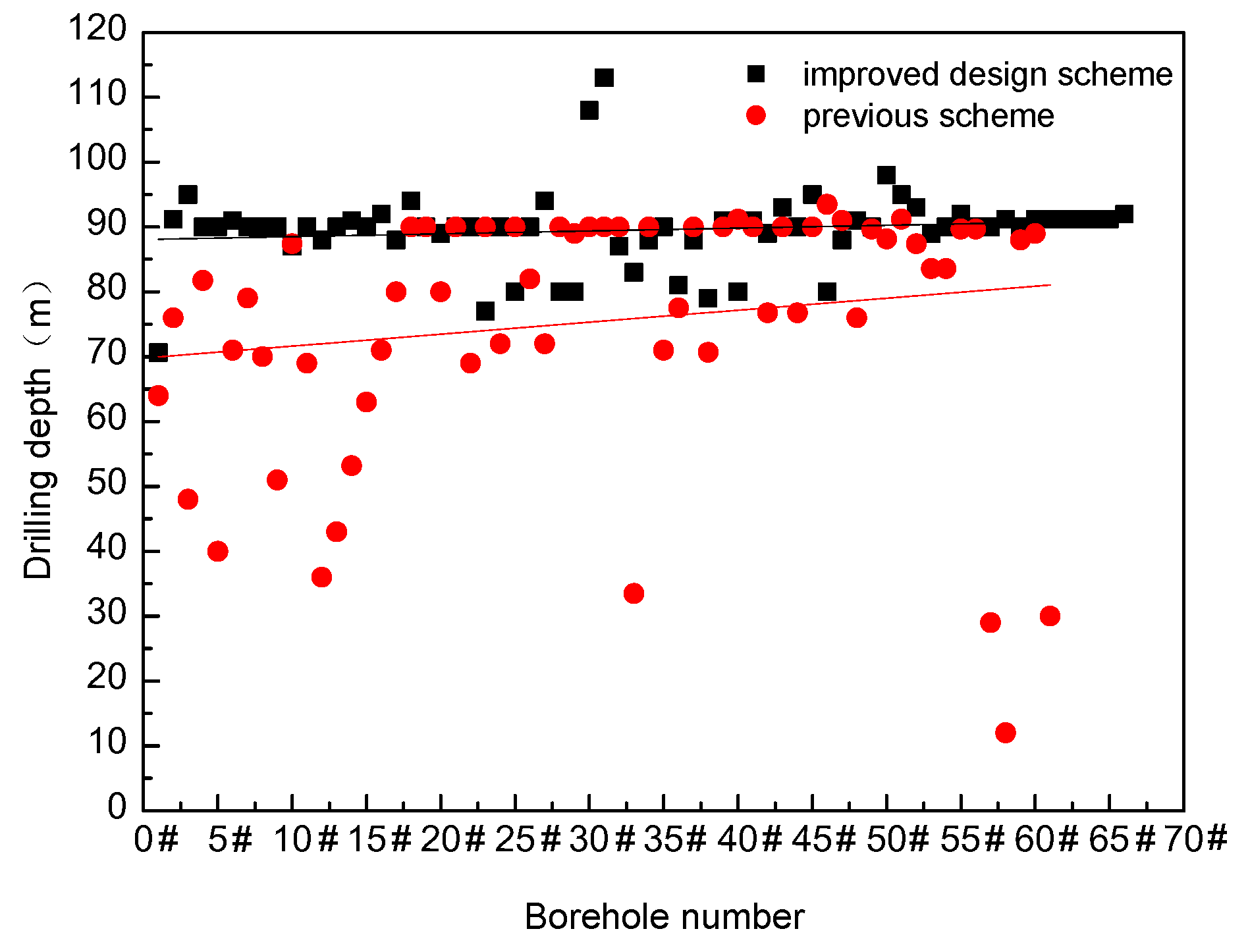
Sixty-one boreholes along the coal seam were drilled using the previous scheme at the test site. The sum depth of the boreholes was 4606 m and the total drilling time was 38 days with an average speed of 121 m/day. Meanwhile, 66 boreholes were drilled along the coal seam using the improved design scheme at the same test site. The sum depth of the boreholes was 5910 m and the total drilling time was about 35 days. The average depth of the boreholes was 89.5 m and the average speed was 169 m/day. The drilling depth had been improved by 18.5% on average and the drilling efficiency had been improved by 39.7%. Figure 12 shows the boreholes numbered sequentially corresponding to the depth data. The requested depth of the boreholes was 90 m. Under the previous scheme, about 25 boreholes reached the design depth, the success rate of which is 41%. Under the improved design scheme, 49 boreholes reached the design depth, the success rate of which is 74% and the deepest borehole was found to be 113 m in length.
6. Conclusions
A mechanical model of clogging segments is established that considers the confining pressure pi that surrounds a borehole. A function for the dredging pressure p and the clogging segment’s length L was derived and the effect of the clogging segment’s length L and the borehole’s angle θ on borehole clogging was discussed.
- (1)
- For soft coal seams, the confining pressure pi plays a leading role in borehole clogging. The higher the confining pressure, the greater the probability that borehole clogging will occur. The confining pressure is the key factor for borehole clogging and results in a shallow depth and low drilling efficiency in the process of drilling in soft coal seams. Therefore, giving priority to prevention, the discharge pressure should be monitored over time and the discharge space should be expanded, to prevent the formation of long clogging segments.
- (2)
- Based on the mechanical model of clogging segments, the drilling scheme that was previously used in the Bai Ping coal mine was evaluated and optimized. The results show that the highest air pressure at the construction site is Pmax = 0.85 MPa and the critical clogging segment length is L0 = 0.3 m, so a clogging segment will not be dredged in time to apply the previous drilling techniques. Accordingly, we put forward the following measures: a reduction in drilling speed from 0.5 m/min to 0.4 m/min, an increase in drill bit diameter from ⌀94 mm to ⌀120 mm and replacing the round drill pipe with a ribbed drill pipe. A p–L equation for the improved drilling technique was established and the results show that the characteristic curve of the improved drilling technique lies to the right of that of the previous scheme, the critical clogging length has been increased from 0.3 m to 0.44 m and the risk of borehole clogging has been lowered.
- (3)
- The results of the field test show that, under the improved scheme, the drilling depth and the drilling efficiency have been improved by 18.5% and 39.7%, respectively. So, the improved drilling technology scheme, which has been developed based on the new mechanical model, is more effective than the previous scheme.
Author Contributions
Y.W. developed the model and wrote the paper; Z.Y. contributed to the engineering application section; and Z.W. contributed to the introduction section.
Funding
This research was funded by National Natural Science Foundation of China [Grant No. 41872188] and Natural Science Funds of Henan Province [Grant No. 182300410126] and Postdoctoral Science Foundation of China [Grant No. 2017M621876].
Conflicts of Interest
The authors declare no conflict of interest.
References
- Wang, L.; Cheng, L.-B.; Cheng, Y.-P.; Yin, G.-Z.; Xu, C.; Jin, K.; Yang, Q.-L. Characteristics and evolutions of gas dynamic disaster under igneous intrusions and its control technologies. J. Nat. Gas Sci. Eng. 2014, 18, 164–174. [Google Scholar] [CrossRef]
- Hamawand, I.; Yusaf, T.; Hamawand, S.G. Coal seam gas and associated water: A review paper. Renew. Sustain. Energy Rev. 2013, 22, 550–560. [Google Scholar] [CrossRef]
- Zou, Q.; Lin, B.; Zheng, C.; Hao, Z.; Zhai, C.; Liu, T.; Liang, J.; Yan, F.; Yang, W.; Zhu, C. Novel integrated techniques of drilling–slotting–separation-sealing for enhanced coal bed methane recovery in underground coal mines. J. Nat. Gas Sci. Eng. 2015, 26, 960–973. [Google Scholar] [CrossRef] [Green Version]
- Zhou, H.; Zhang, R.; Cheng, Y.; Dai, H.; Ge, C.; Chen, J. Methane and coal exploitation strategy of highly outburst-prone coal seam configurations. J. Nat. Gas Sci. Eng. 2015, 23, 63–69. [Google Scholar] [CrossRef]
- Liu, H.; Cheng, Y. The elimination of coal and gas outburst disasters by long distance lower protective seam mining combined with stress-relief gas extraction in the Huaibei coal mine area. J. Nat. Gas Sci. Eng. 2015, 27, 346–353. [Google Scholar] [CrossRef]
- Karacan, C.Ö.; Ruiz, F.A.; Cotè, M.; Phipps, S. Coal mine methane: A review of capture and utilization practices with benefits to mining safety and to greenhouse gas reduction. Int. J. Coal Geol. 2011, 86, 121–156. [Google Scholar] [CrossRef]
- Tian, S.; Jiang, C.; Xu, L.; Yang, D.; Tang, J.; Chen, Y.; Li, X. A study of the principles and methods of quick validation of the outburst-prevention effect in the process of coal uncovering. J. Nat. Gas Sci. Eng. 2016, 30, 276–283. [Google Scholar] [CrossRef]
- Hao, Z.; Zhou, C.; Lin, B.; Pang, Y.; Li, Z. Pressure-relief and permeability-increase technology of high liquid–solid coupling blast and its application. Int. J. Min. Sci. Technol. 2014, 24, 45–49. [Google Scholar] [CrossRef]
- Lu, P.; Yuan, L.; Cheng, H.; Xue, J.; Liu, Z.; Tong, Y.; Wang, Y.; Cai, R.; Deng, Z. Theory and experimental studies of enhanced gas drainage in the high-gas face of low permeability coal multi-seams. J. China Coal Soc. 2010, 35, 580–585. [Google Scholar]
- Wang, Y.; Zhai, X.; Sun, Y. Reasonable parameters study on grooved drill pipe used in drilling outburst coal seam. J. China Coal Soc. 2011, 36, 304–307. [Google Scholar]
- Li, D.; Zhang, S.; Zhang, S. Experimental and numerical simulation study on fracturing through interlayer to coal seam. J. Nat. Gas Sci. Eng. 2014, 21, 386–396. [Google Scholar] [CrossRef]
- Yuan, L. Theory of pressure relieved gas extraction and technique system of integrated coal production and gas extraction. J. China Coal Soc. 2009, 34, 1–8. [Google Scholar]
- Tang, J.; Lu, Y.; Ge, Z.; Xia, B.; Sun, H.; Du, P. A new method of combined rock drilling. Int. J. Min. Sci. Technol. 2014, 24, 1–6. [Google Scholar] [CrossRef]
- Szlązak, N.; Obracaj, D.; Swolkień, J. Methane drainage from roof strata using an overlying drainage gallery. Int. J. Coal Geol. 2014, 136, 99–115. [Google Scholar] [CrossRef]
- Fang, X.; Geng, Y.; Wang, M. Kilometer directional drilling: Simultaneous extraction of coal and gas from a high gas coal seam. J. China Univ. Min. Technol. 2012, 41, 885–892. [Google Scholar]
- Sun, Y.; Wang, Y.; Zhai, X. Analysis on reasons of drilling difficulty in soft and outburst coal seam. J. China Coal Soc. 2012, 37, 117–121. [Google Scholar]
- Liu, C.; Zhou, F.; Yang, K.; Xiao, X.; Liu, Y. Failure analysis of borehole liners in soft coal seam for gas drainage. Eng. Fail. Anal. 2014, 42, 274–283. [Google Scholar] [CrossRef]
- Wang, Y.; Sun, Y.; Wang, Z.; Song, W. Mechanical characteristic of borehole clogging drilling in soft and outburst coal seam. J. China Coal Soc. 2015, 40, 119–125. [Google Scholar]
- Bai, J.; Li, N.; Zhong, X.; Zhang, Y.; Xu, J.; Xi, B.; Liu, H. Effect of bulk density of coking coal on Audibert-Arnu dilatation. J. China Coal Soc. 2012, 37, 332–335. [Google Scholar]
- Shi, S.; Lei, Y.; Cao, S.; Zhang, K.; Wu, Q.; Li, F. Influence of the bulk density of coal charge on the performance of stamp coking coke. J. Wuhan Univ. Sci. Technol. 2011, 34, 285–288. [Google Scholar]
- Dai, X.; Gu, D. Theoretical analysis and calculation of lateral pressure coefficient in granular materials. Nonferr. Met. 1992, 44, 19–23. [Google Scholar]
- Xie, B.; Zhu, C.; Cui, D. Theoretical analysis and experimental study on pressure of silo. J. Liaoning Tech. Univ. 2007, 26, 226–227. [Google Scholar]
- Yao, N.; Sun, R.; Ye, G. Equipment and technology of borehole construction for gas drainage in China underground mines. Coal Sci. Technol. 2008, 36, 12–16. [Google Scholar]
Figure 1.
Expanded images of the borehole. (a) a few irregular fissures; (b) a transition area with more damage; (c) a small area borehole collapse and (d) a large area borehole collapse.
Figure 1.
Expanded images of the borehole. (a) a few irregular fissures; (b) a transition area with more damage; (c) a small area borehole collapse and (d) a large area borehole collapse.

Figure 2.
A clogging segment formed in a normal borehole.
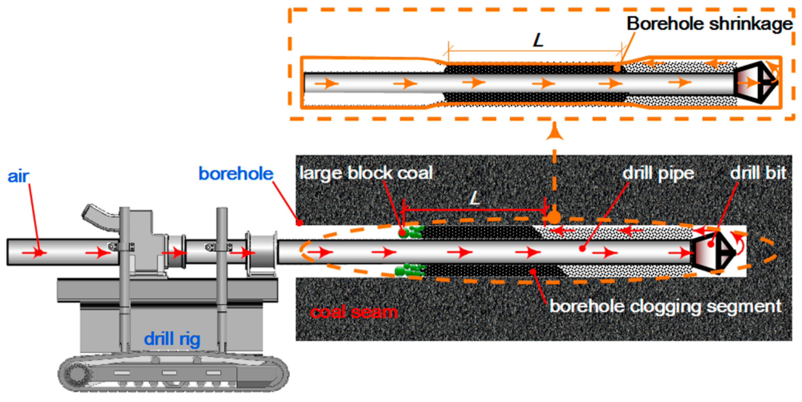
Figure 3.
The stress state of the clogging segment: (a) borehole-axial section; and (b) borehole-cross-section.
Figure 3.
The stress state of the clogging segment: (a) borehole-axial section; and (b) borehole-cross-section.
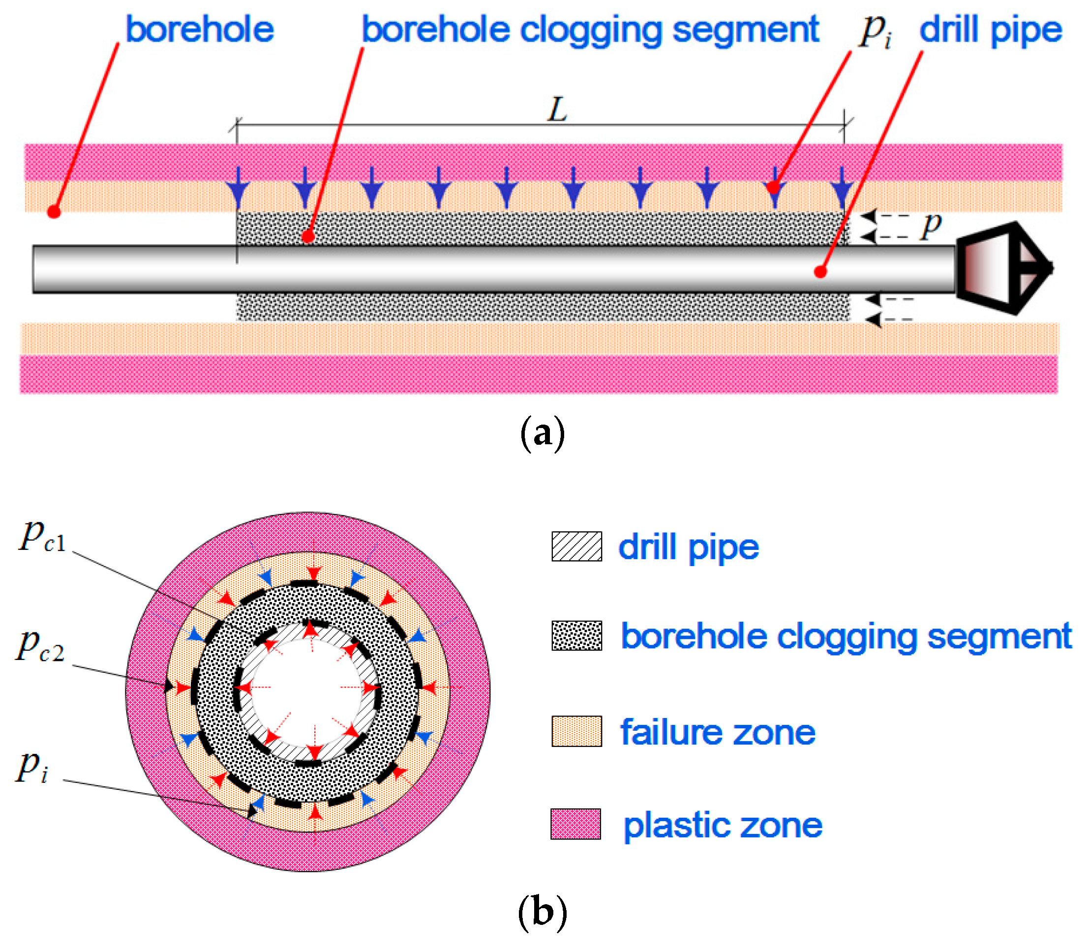
Figure 4.
The mechanical model of a clogging segment in an upward borehole.
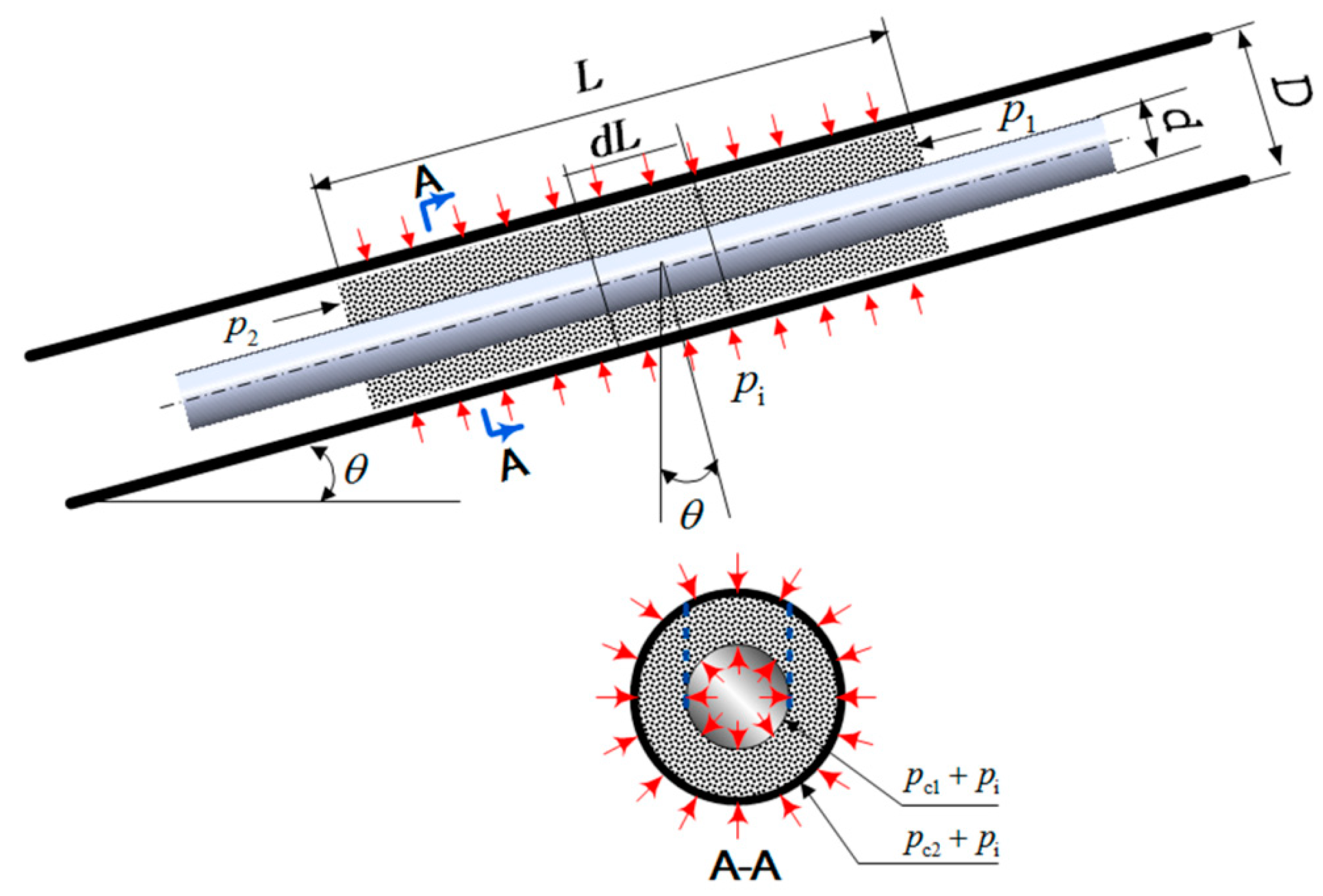
Figure 5.
Borehole clogging in different drill pipes. (a) a round drill pipe; (b) a spiral drill pipe.
Figure 5.
Borehole clogging in different drill pipes. (a) a round drill pipe; (b) a spiral drill pipe.

Figure 6.
Curves of the relationship between the dredging pressure and the clogging segment’s length.
Figure 6.
Curves of the relationship between the dredging pressure and the clogging segment’s length.
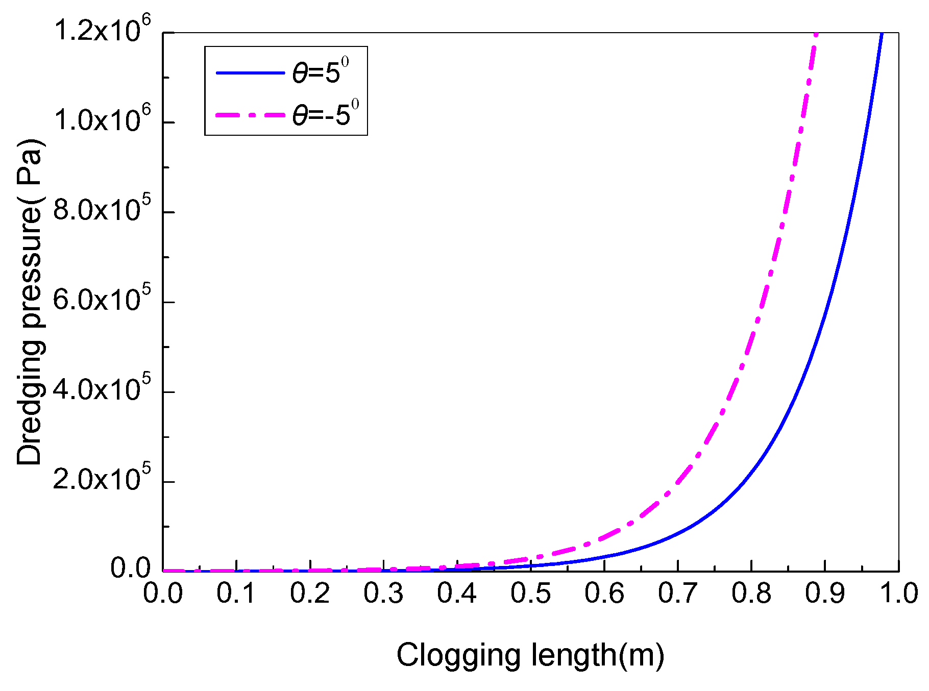
Figure 7.
Curves of the relationship between the dredging pressure and the drilling angle.
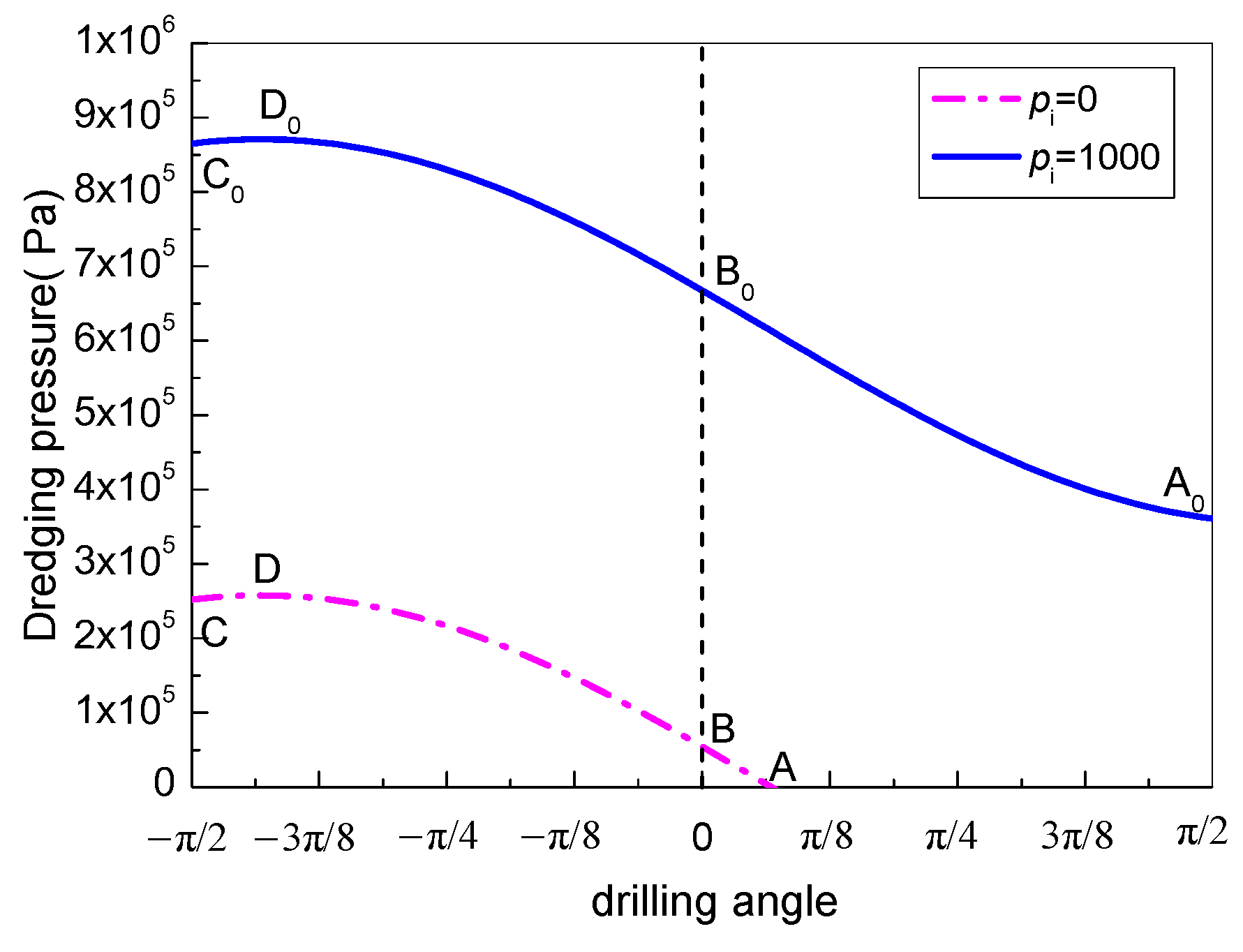
Figure 8.
Curves of the relationship between the dredging pressure and the drilling angle under different confining pressures.
Figure 8.
Curves of the relationship between the dredging pressure and the drilling angle under different confining pressures.

Figure 9.
The flow diagram for the mechanical model of borehole clogging in the engineering application.
Figure 9.
The flow diagram for the mechanical model of borehole clogging in the engineering application.
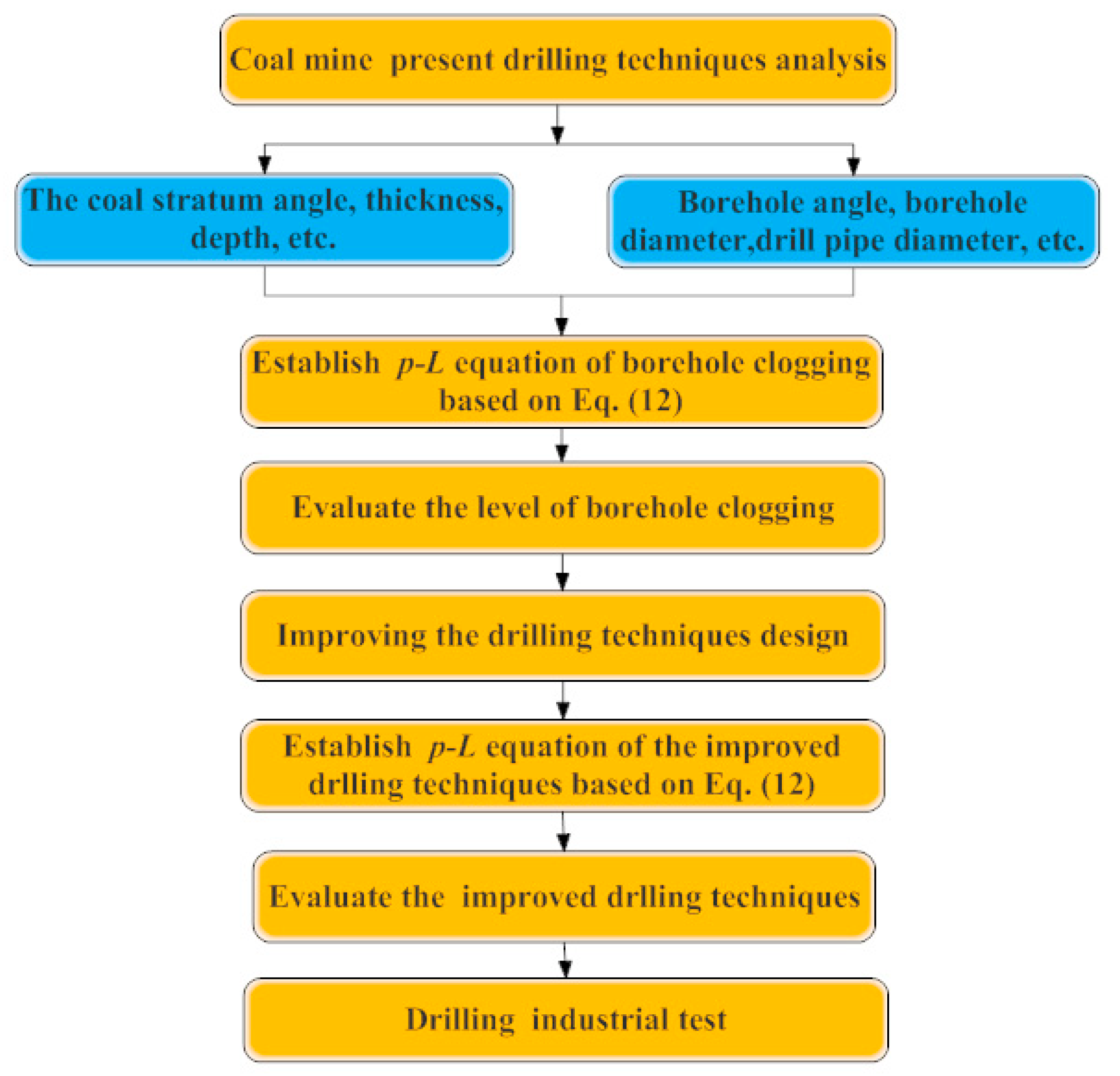
Figure 10.
The p–L characteristic curve under the parameters of the drilling technology.
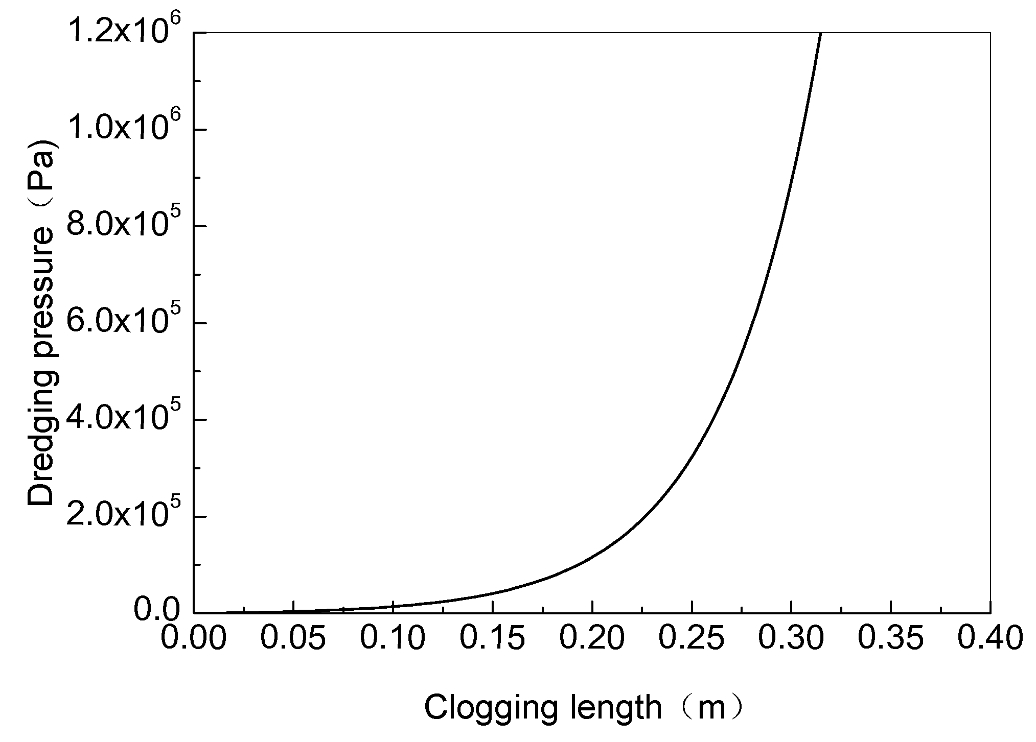
Figure 11.
Comparison of the p–L characteristic curves between the improved design and the previous scheme.
Figure 11.
Comparison of the p–L characteristic curves between the improved design and the previous scheme.
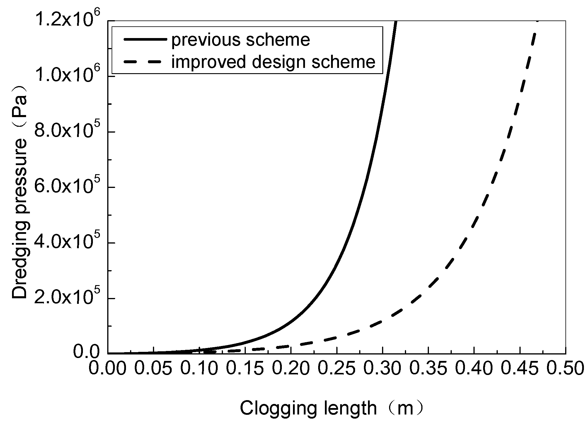
Figure 12.
Comparison of the data from the engineering application.


Table 1.
The parameters of the drilling technology.
| Borehole Angle (°) | Borehole Diameter (m) | Drill Pipe Diameter (m) | Lateral Pressure Coefficient | Confining Pressure (Pa) | Friction Factor f1 | Friction Factor f2 |
|---|---|---|---|---|---|---|
| 5 | 0.094 | 0.073 | 0.5 | 1000 | 0.1 | 0.3 |
© 2018 by the authors. Licensee MDPI, Basel, Switzerland. This article is an open access article distributed under the terms and conditions of the Creative Commons Attribution (CC BY) license (http://creativecommons.org/licenses/by/4.0/).
Share and Cite
MDPI and ACS Style
Wang, Y.; Yu, Z.; Wang, Z. A Mechanical Model of Gas Drainage Borehole Clogging under Confining Pressure and Its Application. Energies 2018, 11, 2817. https://doi.org/10.3390/en11102817
AMA Style
Wang Y, Yu Z, Wang Z. A Mechanical Model of Gas Drainage Borehole Clogging under Confining Pressure and Its Application. Energies. 2018; 11(10):2817. https://doi.org/10.3390/en11102817
Chicago/Turabian StyleWang, Yonglong, Zaijiang Yu, and Zhenfeng Wang. 2018. "A Mechanical Model of Gas Drainage Borehole Clogging under Confining Pressure and Its Application" Energies 11, no. 10: 2817. https://doi.org/10.3390/en11102817
Note that from the first issue of 2016, this journal uses article numbers instead of page numbers. See further details here.