Article

Suggestion of a Scale Factor to Design Spiral-Coil-Type Horizontal Ground Heat Exchangers

1
Applied Science Research Institute, Korea Advanced Institute of Science and Technology, Daejeon 34141, Korea
2
Department of Civil and Environmental Engineering, Korea Advanced Institute of Science and Technology, Daejeon 34141, Korea
3
Division of Radioactive Waste Disposal Research, Korea Atomic Energy Research Institute, Daejeon 34057, Korea
*
Author to whom correspondence should be addressed.
Energies 2018, 11(10), 2736; https://doi.org/10.3390/en11102736
Submission received: 19 July 2018 / Revised: 10 October 2018 / Accepted: 10 October 2018 / Published: 12 October 2018

Abstract

:
Spiral-coil-type horizontal ground heat exchangers (GHEs) have been increasingly used in ground source heat pump (GSHP) systems due to their higher heat transfer performance. Many attempts have been made to investigate the heat transfer mechanism and establish design methods for the spiral-coil-type ground heat exchangers. Nevertheless, a universal design method for horizontal GHEs has not been reported due to its complexity. In contrast to the spiral-coil-type horizontal GHEs, straight-line-type horizontal GHEs have been widely adopted since they are easy to design for use in industry. In this study, a scale factor model, which could be used to design the coil-type exchanger based on the design length of a straight-line-type heat exchanger, was presented. The ratio of the mean thermal transfer energy between the straight-line-type and spiral-coil-type heat exchangers was numerically investigated by considering weather condition, configuration of GHE, and thermal properties of the ground. Using the numerical results for a total of 108 cases, artificial neural network and linear regression methods were employed for the model development. The proposed model of the scale factor may provide an alternative way to design the spiral-coil-type horizontal GHEs.

1. Introduction

Reducing fossil energy consumption and addressing climate change are inevitable and urgent global challenges for the sustainable development of all countries [1]. One active action is to increase the use of renewable energy sources that produce low or no emissions, such as wind, solar, and geothermal energy [2]. Geothermal energy has been mainly used for the production of electricity and space heating and cooling. The use of geothermal energy is expected to increase consistently, as forecasts predict the geothermal power capacity will be over 16 GW in 2020 [3].
In Korea, geothermal energy has mostly been utilized for heating and cooling applications through the closed-loop-type ground source heat pump (GSHP) system. A GSHP system consists of three main components: the heat pump unit, ground heat exchanger (GHE), and heat distribution system. By circulating the working fluid through a GHE, the heat can be released to the ground in summer, and extracted from the ground in winter [4]. The shares of closed-GSHP systems in Korea reached almost 80% in 2012 [5]. Two types of ground heat exchanger are generally utilized in the closed-GSHP system: one is the vertical GHE, which is installed in a borehole more than 150 m in length, and the other is the horizontal GHE, which is installed 2–3 m deep below the ground surface [6,7]. In general, the vertical GHEs have high efficiency and low land demand, but they require expensive costs for borehole drilling. Conversely, the horizontal GHEs have an advantage of low excavation costs but they are required in a sufficient area to meet a given heat exchangers requirement because of low efficiency [8,9,10].
Many researchers have carried out investigations to characterize the heat transfer mechanism and to improve the efficiency of horizontal GHEs numerically and experimentally. Depending on the configuration of horizontal GHE, the linear type [9,10,11], slinky type [12,13,14,15,16], and spiral-coil type [17,18,19,20,21] were considered.
Congedo et al. [18] investigated the thermal performance of three different types of GHE with consideration of the pitch size of coil, depth of installation, thermal conductivity of the ground, and heat transfer fluid velocity using ANSYS Fluent software. They found that the most important factor for the heat transfer performance is the thermal conductivity of the ground, while the depth of installation was found to have negligible effect. Dasare and Saha [17] also investigated the factors affecting thermal performance of linear, slinky, and helix (spiral coil) horizontal GHEs numerically. They concluded with results similar to that of Congedo et al. [18]. Kim et al. [19] conducted the small-scale experimental and numerical analyses to investigate the effect of thermal conductivity and pipe diameter on the thermal performance of slinky and spiral-coil-type horizontal GHE. They revealed that the pipe diameter is not a critical factor.
Studies on the effect of the configuration on the performance of horizontal GHEs revealed that the spiral-coil-type horizontal GHE exhibited higher heat transfer performance compared with that of the straight line and slinky-type horizontal GHEs [17,18,19]. However, the influencing factors considered for the performance of spiral-coil-type GHEs differed between each study. The considered factors were the thermal conductivity of the ground (from 1 W/(m∙K) to 4 W/(m∙K)), velocity of the fluid (from 0.25 m/s to 1 m/s), and depth of installation (from 1.5 m to 2.5 m) in the study of Dasare and Saha [17], the velocity of the fluid (from 0.25 m/s to 1 m/s), thermal conductivity of the ground (from 1 W/(m∙K) to 3 W/(m∙K)), depth of installation (from 1.5 m to 2.5 m) and pitch size of the coil (from 0.1 m to 0.4 m) in the study of Congedo et al. [18], and thermal conductivity of the ground (from 0.26 W/(m∙K) to 1.1 W/(m∙K)), and pipe diameters (from 20 mm to 32 mm) in the study of Kim et al. [19]. Therefore, the consideration of more factors, such as the weather conditions, thermal properties of the ground, configuration of the spiral-coil-type GHE, and time, is likely required in order to investigate their influence on the performance of spiral-coil-type GHEs in more detail.
In the design of a GSHP system with horizontal GHE, the exact calculation of the trench length of the horizontal GHE is significantly important [20]. The trench length of a horizontal line and slinky-type GHE can be determined using commercial design programs such as ground loop design (GLD) and ground loop heat exchanger pro (GLHEPRO) [22,23]. Despite the superior performance of spiral-coil-type horizontal GHEs, only one research has been conducted on a design method for calculating the trench of spiral-coil-type horizontal GHEs. Kim et al. [20] proposed a design method for spiral-coil-type horizontal GHEs by modifying the boundary conditions of an equation proposed by Kavanaugh and Rafferty [24] and employing the mathematical model proposed by Jeon et al. [21]. Even though the applicability of design method was verified using a laboratory thermal response test and numerical simulation, it is still hard to use compared with the commercial design program.
Therefore, the objective of this paper was to investigate the performance of spiral-coil-type horizontal ground heat exchangers in more detail and to suggest an alternative way to estimate the trench length using a scale factor. To achieve this, a scale factor that could be used to design spiral-coil-type exchangers based on the design length of a straight-line-type heat exchanger was presented. The performance of the spiral-coil-type GHE was investigated using the three-dimensional numerical model through a parametric study. Based on the numerical results, the scale factor model was developed using artificial neural network (ANN) and linear regression methods.

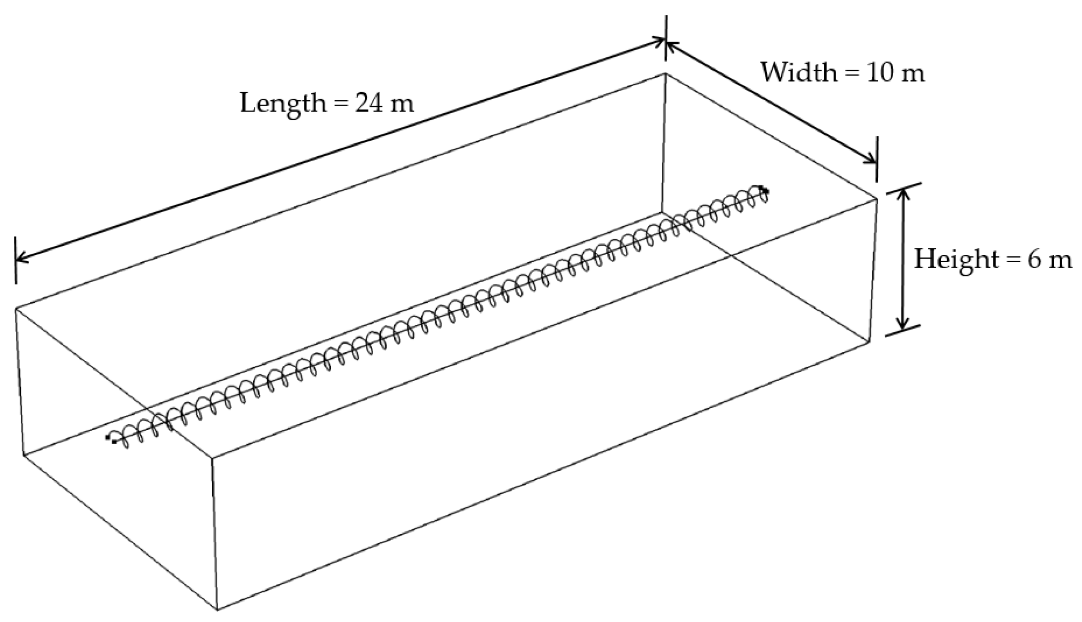
2. Description of Numerical Modeling

A three-dimensional numerical model including the horizontal ground heat exchanger and the surrounding ground was developed using a finite element numerical simulator, COMSOL Multiphysics Ver. 5.2a. Governing equations used in the numerical model were identical to those in the study of Jeon et al. [25]. To simplify the numerical model, the following assumptions have been made in this study:
  • The ground was assumed to be a solid medium, not a porous medium.
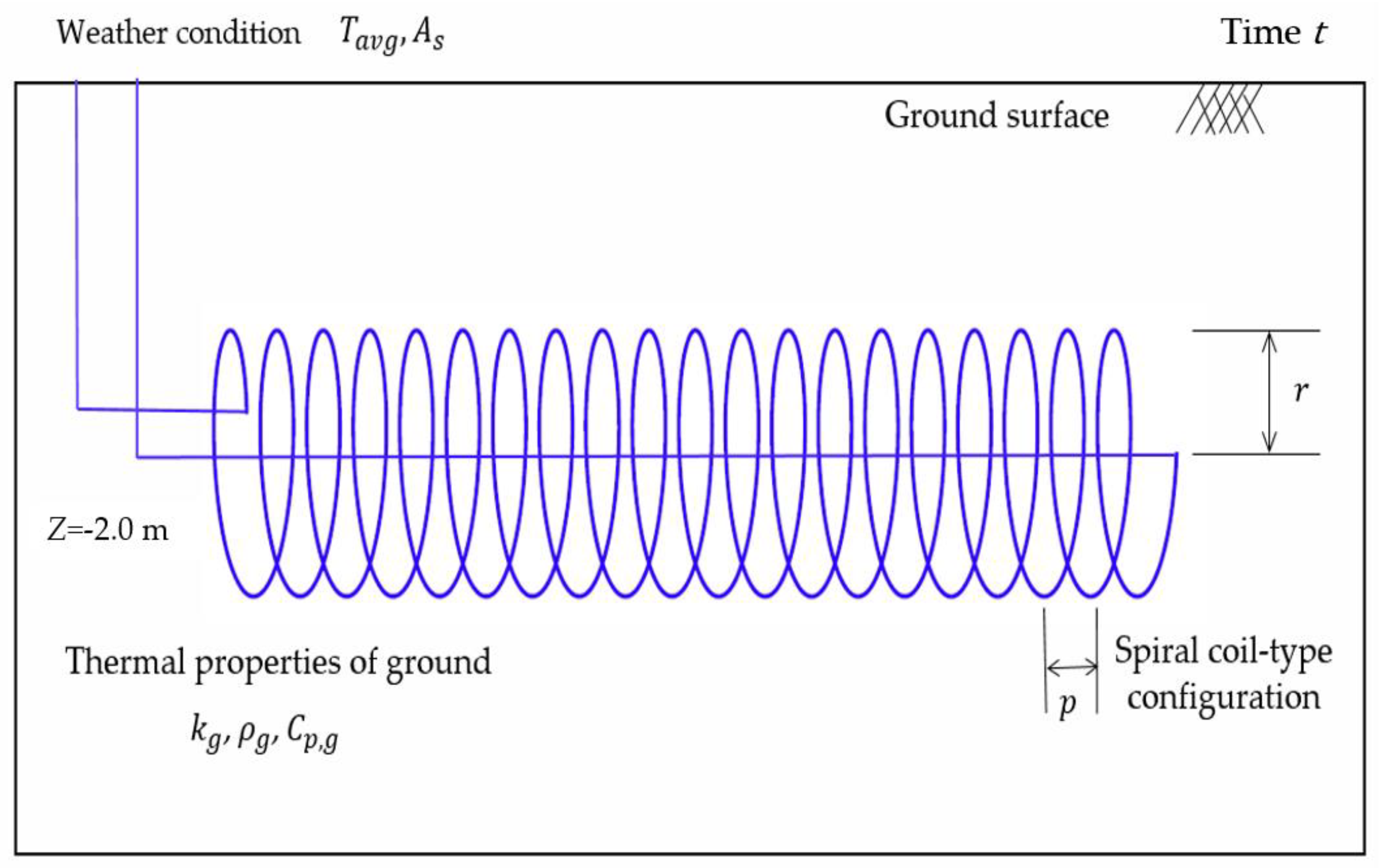
  • The ground heat exchanger (GHE) was installed at a 2.0 m depth from the ground surface.
  • The material of the GHE was a high-density polyethylene (HDPE) pipe with a thermal conductivity of 0.38 W / ( m · K ) and a 2 mm thickness.
A three-dimensional numerical model having a size of 10 m width × 24 m length × 6 m height is shown in Figure 1.
The material of the horizontal GHEs was assumed to be an HDPE circular pipe with an outer diameter of 0.02 m, 0.002 m thickness, and a surface roughness of 0.00015 mm. The horizontal GHEs were modeled as line elements with an imaginary diameter, and the soil domain was discretized using tetrahedral elements. To determine the element size, a grid independent test was conducted by monitoring the change in the outlet fluid temperature. A total number of 160,000 elements were adopted in consideration of the computation effort and accuracy of the solution. The temperature and mass flow of the inlet fluid were designated a constant temperature of 37.9 °C and 0.162 kg/s, respectively. Afterwards, the temperature of the outlet fluid was monitored with time. The difference between inlet and outlet fluid temperatures represented how much thermal energy was released to the surrounding ground. To evaluate the performance of the straight line and spiral-coil-type horizontal GHEs, the heat-transferred thermal energy was obtained as follows:
Q L = m ˙ C p , f ( T i n T o u t ) L
where m ˙ is the mass flow rate ( kg / s ), C p , f is the specific heat of water ( J / ( kg · K ) ), T i n is the temperature of the inlet fluid ( K ), T o u t is the temperature of the outlet fluid ( K ), and L is the length of the ground heat exchanger ( m ).
Although a mixture of water with antifreeze is generally used as the circulating fluid for GHEs to ensure the stability of the GSHP system in cold climates, only water was considered in this study. In addition, the properties of the ground as well as those of the circulating fluid were assumed to be constant. Because the ground temperature has a significant effect on the performance of the horizontal ground heat exchanger, the ground temperature distribution with varying time and depth should be considered [26,27,28,29]. Based on the pure heat conduction theory, an analytical solution for the ground temperature distribution was employed [30].
  T ( z , t ) = T a v g + A s e x p { z 2 / ( 2 π / 365 ) } c o s { ( 2 π / 365 ) ( t φ ) + z 2 / ( 2 π / 365 ) }  
where T a v g is the annual average soil temperature (°C), A s is the annual amplitude of the surface temperature (°C), is the soil diffusivity ( m 2 / s ), t is the time of year, and φ is the phase change (radian).
The initial temperature was assumed to be uniform and identical to the ground temperature distribution. All the boundaries, except the ground surface (i.e., bottom and side boundaries), were thermally insulated.

3. Parametric Study

To investigate the performance difference between the straight line and spiral-coil-type GHEs, a scale factor that was defined as the ratio of the mean thermal transferred energy for the spiral-coil-type GHE to that for the straight-line-type GHE was introduced.
  Scale   factor = Q s p i r a l Q l i n e  
The considered factors used in the parametric study were mainly categorized into four parts: weather conditions, configuration of the spiral-coil-type GHE, thermal properties of the ground, and time (Figure 2). The values of considered factors were determined based on the investigation of previous studies: weather conditions [31], configuration of the spiral-coil-type GHE [19,32,33,34,35] and thermal properties of the ground [13,35,36,37,38]. The range of these factors was chosen more conservatively than previous studies in order to cover typical conditions used in the real field (Table 1). The thermal properties of the ground represent the thermal properties of not only general ground but also the backfill material, such as controlled low-strength material (CLSM), thermally enhanced backfilling material, etc. Although the backfill is generally performed using the excavated soil, the new backfill material was recently employed in order to improve workability and performance of the spiral-coil-type ground heat exchanger [39,40]. In addition, the high thermal conductivity of the ground which is scarce in nature at shallow depths was investigated for the purpose of research.
Consideration of the phase change ( φ ) of weather conditions was excluded because it represents the regional characteristics and is generally ignored in the design stage (considering only the highest and lowest ground temperatures). To investigate the main and interaction effects, all combinations were considered in this study.

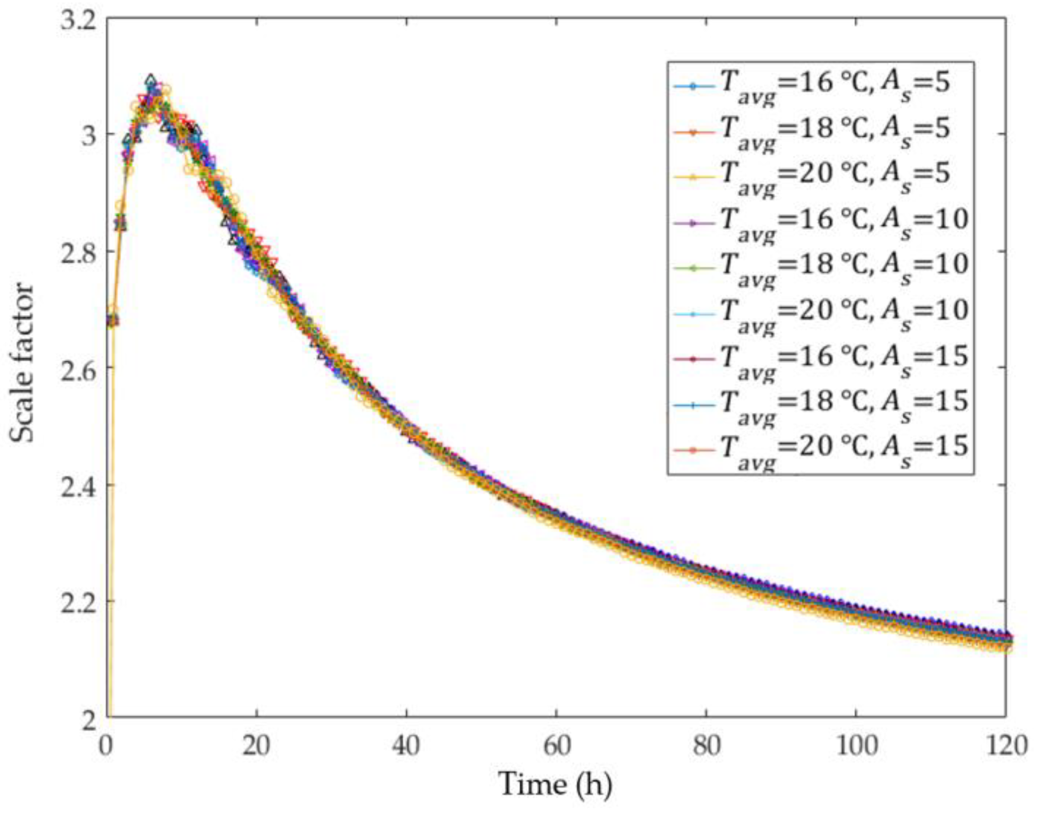
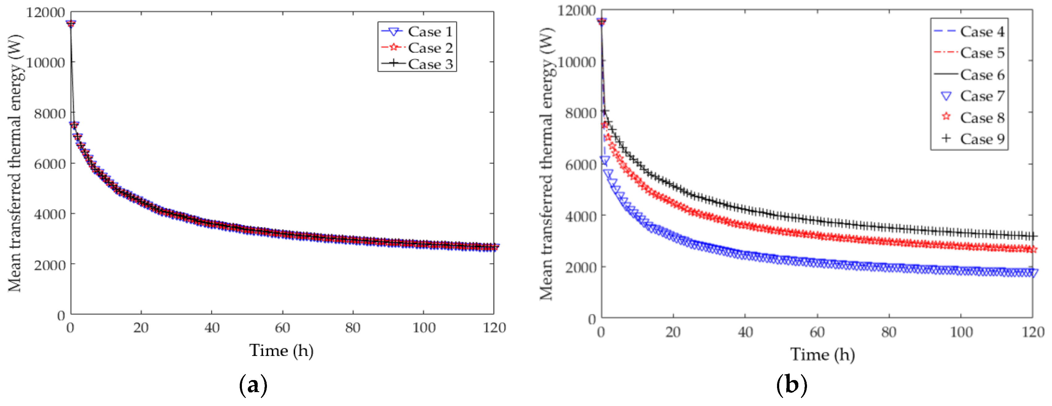
3.1. Effect of Weather Conditions

Nine cases were considered to investigate the effect of the weather conditions on the scale factor, as listed in Table 2. Except the weather conditions, all parameters were fixed as constant values. The radius of coil, pitch size of coil, thermal conductivity of the ground, and specific heat capacity of the ground were set to 0.15 m, 0.3 m, 2.4 W/(m∙K), and 900 J/(kg∙K), respectively. The variations of the scale factor corresponding to each case are depicted in Figure 3.
Although small fluctuations were observed during the initial 20 h, the overall trend was quite similar in all cases. To highlight the differences between the scale factors, relative errors were calculated by selecting Case 4 as a base case, where the annual soil temperature is 16 °C and the annual amplitude of the surface temperature is 10 °C. As summarized in Table 3, the influence of the weather conditions on the scale factor could be ignored because the maximum value of the average relative errors was less than 1% (exactly, 0.507%). However, this does not mean that the influence of the weather conditions on the performance of horizontal ground heat exchangers is negligible. Although the performance of the straight-line and spiral-coil-type GHEs changed with the weather conditions, there were only small changes in the scale factor because the increasing/decreasing rate of performance was identical.

3.2. Effect of Thermal Properties of the Ground

To evaluate the effect of the thermal properties of the ground, different values of specific heat, density, and thermal conductivity of the ground were considered, as shown in Table 4.
The mean transferred thermal energy values for each case were plotted in Figure 4. From Case 1 to Case 3, the specific heat and density were different with identical thermal conductivity and volumetric heat capacity values. Figure 4a shows the plots of the mean transferred thermal energy for Case 1, 2, and 3. It indicates that the mean transferred thermal energies were exactly the same. Figure 4b describes the mean transferred thermal energy obtained from Case 4–9. The density of the ground was fixed as a constant for Case 4, 5, and 6, and the specific heat was constant in Case 7, 8, and 9. The results for Case 4, 5, and 6 were equal to those of Case 7, 8, and 9, respectively. Even though the specific heat and density were different, the mean transferred thermal energies were identical if the volumetric heat capacity and thermal conductivity were equal. This implies that the variations in the specific heat and density have no influence on the performance of the horizontal GHE if the volumetric heat capacity is identical. As the volumetric heat capacity increases, the rate of ground temperature rise decreases for the identical heat source. Consequently, more thermal energy could be transferred into the surrounding ground by heat exchangers as the volumetric heat capacity of ground increases.
Based on the above findings, three additional cases were considered for investigating the effect of the thermal properties of the ground in more detail:
  • Case A. The increase/decrease in the thermal conductivity when the volumetric heat capacity is identical ( k g = 1.5, 2.4, 3.0 W / ( m · K ) , C p , g · ρ g = 1800 kJ / ( kg · m 3 ) ).
  • Case B. The increase/decrease in the product of the volumetric heat capacity and the thermal conductivity when the thermal diffusivity is identical ( C p , g · ρ g · k g = 1687.5, 4320, 6750 kJ / ( K · m 3 ) · W / ( m · K ) , = 1.333 mm 2 / s ).
  • Case C. The increase/decrease in the volumetric heat capacity when the thermal conductivity is identical ( C p , g · ρ g = 1125, 1800, 2250 kJ / ( K · m 3 ) , k g = 1.5 W / ( m · K ) ).
Figure 5 and Figure 6 present variations in the scale factor with pitch sizes (0.1 m, 0.3 m, 0.5 m) and coil radii (0.1 m, 0.3 m, 0.5 m) with respect to the first and second case, respectively. As the thermal conductivity of the ground increased, the scale factor also increased when the ratio of the radius to pitch size was less than unity, approximately. Above this ratio, however, the scale factor decreased even though the thermal conductivity of the ground increased. Similar trends were also observed when the values of the product of the volumetric heat capacity and the thermal conductivity were varied. Unlike the results of Case A, however, the value of scale factor increased only in the initial 30 h as the value of the product of the volumetric heat capacity and the thermal conductivity decreased when the ratio of the radius to pitch size was higher than unity. These results imply that the effects of the ground thermal properties (thermal conductivity and volumetric heat capacity) and the spiral coil configuration have to be considered simultaneously to determine the scale factor.
Figure 7 shows the change in scale factor for different volumetric heat capacities when the thermal conductivity is identical. Variation trends for the scale factor corresponding to each configuration were similar for the change in volumetric heat capacity. When the volumetric heat capacity was low, a dramatic change in the scale factor was observed at the initial stage. At the steady-state condition, at approximately 120 h, the scale factor increased with the increase in the volumetric heat capacity. This implies that the correlation between the volumetric heat capacity and performance of spiral-coil-type horizontal GHEs varies with time.

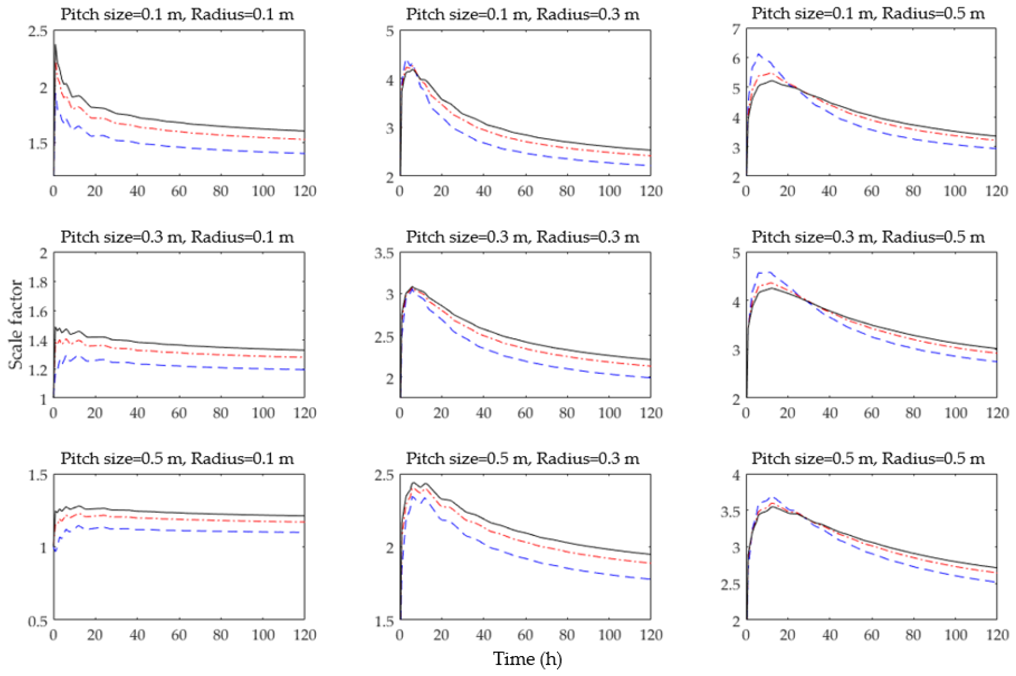
3.3. Effect of Spiral Coil Configuration

Nine cases were considered in order to investigate the effect of the spiral-coil configuration with different coil radii and pitch sizes, as listed in Table 5.
Figure 8 and Figure 9 describe the effect of the pitch size with identical ratios of the coil radius to the pitch size and the effect of coil radius when the pitch size is equal. The larger pitch size resulted in a higher scale factor when the volumetric heat capacity, thermal conductivity, and ratio of the pitch size to radius were equal. In addition, a higher scale factor was obtained for the larger radius when the volumetric heat capacity, thermal conductivity, and pitch size were equal. These results were caused by the different ground temperature surrounding the ground heat exchanger. When the spiral-coil-type GHE with a large coil radius was used, the distance between the coil source and the central line of the GHEs also increased. Since the ground temperature varied with the depth, the temperature of the ground surrounding the GHEs also changed with the coil radius.

4. Development of the Scale Factor Model

According to the results of the parametric study, five factors, such as the thermal conductivity of the ground, volumetric heat capacity of the ground, radius of the coil, pitch size, and time, had a significant influence on the scale factor, among the initially considered factors shown in Table 1. A total of 108 data sets were established using all combinations of the five factors, and then the scale factor models were developed using MATLAB (R2016a) software.

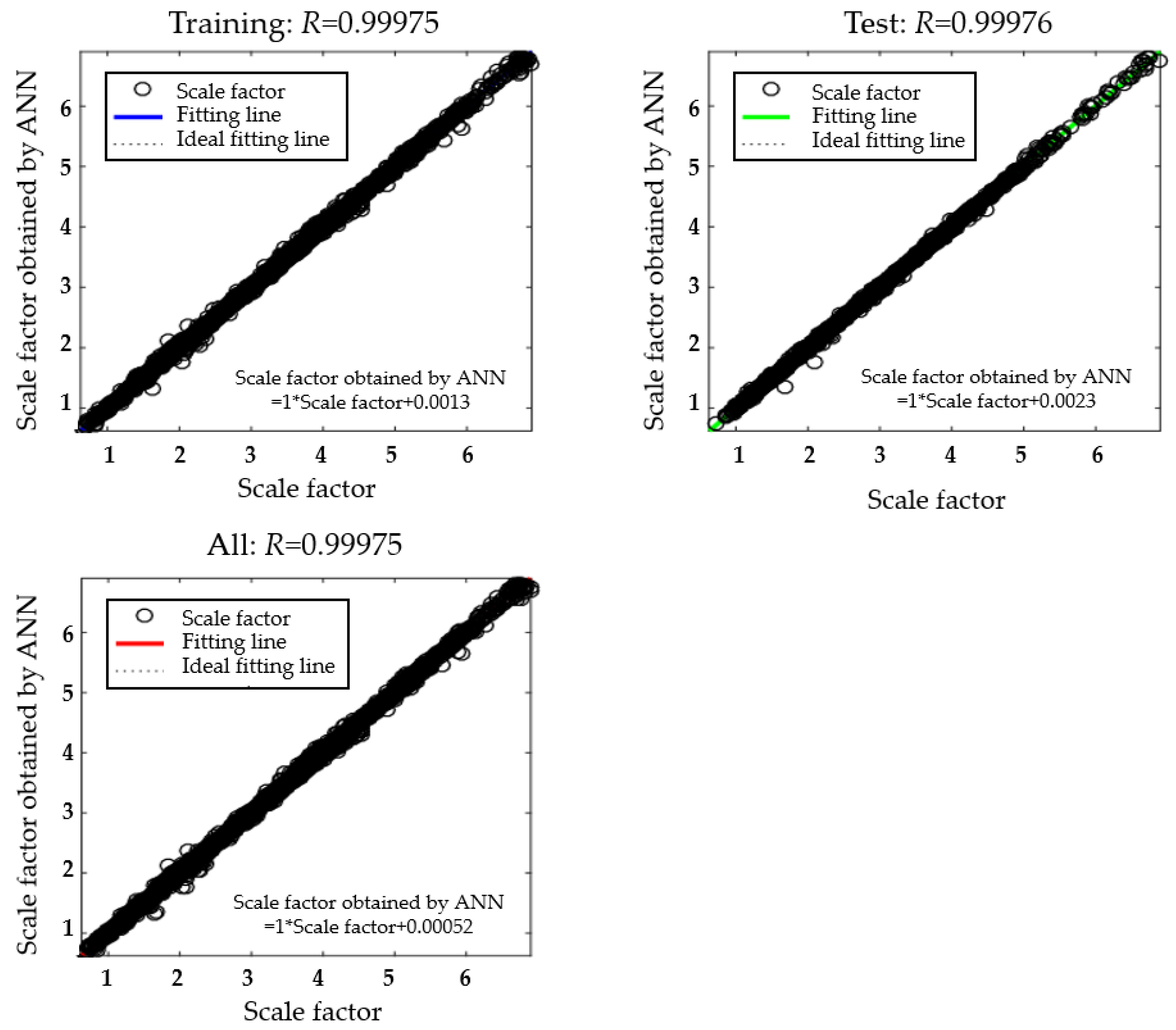
4.1. Artificial Neural Networks (ANN) Model

As the representative method of artificial intelligence (AI), the artificial neural network has been used in various fields, such as engineering, economics, mathematics, and medicine. It is inspired by the human brain structure, which consists of a large number (approximately 10 11 ) of highly connected elements called neurons. The function of the neural network is established by connections between the elements [41]. To ensure that the neural network performs a specific function, these weighted connections are adjusted to be stronger or weaker through the training (or learning) process. The artificial neural network consists of inputs, weights, total functions, activation functions, and outputs, as shown in Figure 10.
The number of neurons in the hidden layer was set to 20. Tangent sigmoid and liner functions were used as activation functions in the hidden and output layer, respectively. To avoid the overfitting problem, the regularization and early stopping technique were implemented in the neural network toolbox. In addition, the Bayesian regularization training function provides better generalization performance than early stopping technique when the data set is small [42]. Therefore, the Bayesian regularization training function was used in this study. Since the Bayesian regularization training function does not require the data for validation, the dataset was divided into a training dataset (80% of all datasets) and a testing dataset (20% of all datasets).
Figure 11 shows the regression results of the developed ANN model. The correlation coefficient for the training, testing, and all datasets were 0.99975, 0.99976, and 0.99975, respectively.

4.2. Linear Regression Model

A linear model containing an intercept, linear terms, and all the products of the pairs of distinct predictors (same as the five factors) was initially selected. After, some pairs of distinct predictors with estimated coefficients having a p-value higher than 0.05 were excluded because the p-value higher than 0.05 indicates that those predictors do not have a significant impact on the scale factor.
Table 6 shows the final estimated coefficients and their p-values. The coefficient of determination for the linear regression model was also almost 1.0 (exactly, 0.99). The linear regression model for scale factor can be expressed as follows:
Scale   factor = 0.56062 + 0.2345 k g + 7.2827 × 10 8 C p , g · ρ g 0.69099 p + 7.8501 r 0.0010938 t 1.9364 × 10 8 k g · C p , g · ρ g 0.062123 k g · p 3.5181 × 10 7 0.72633 k g · r 9.2097 × 10 7 C p , g · ρ g · r 2.5257 p · r + 0.0092101 p · t 0.02712 r · t

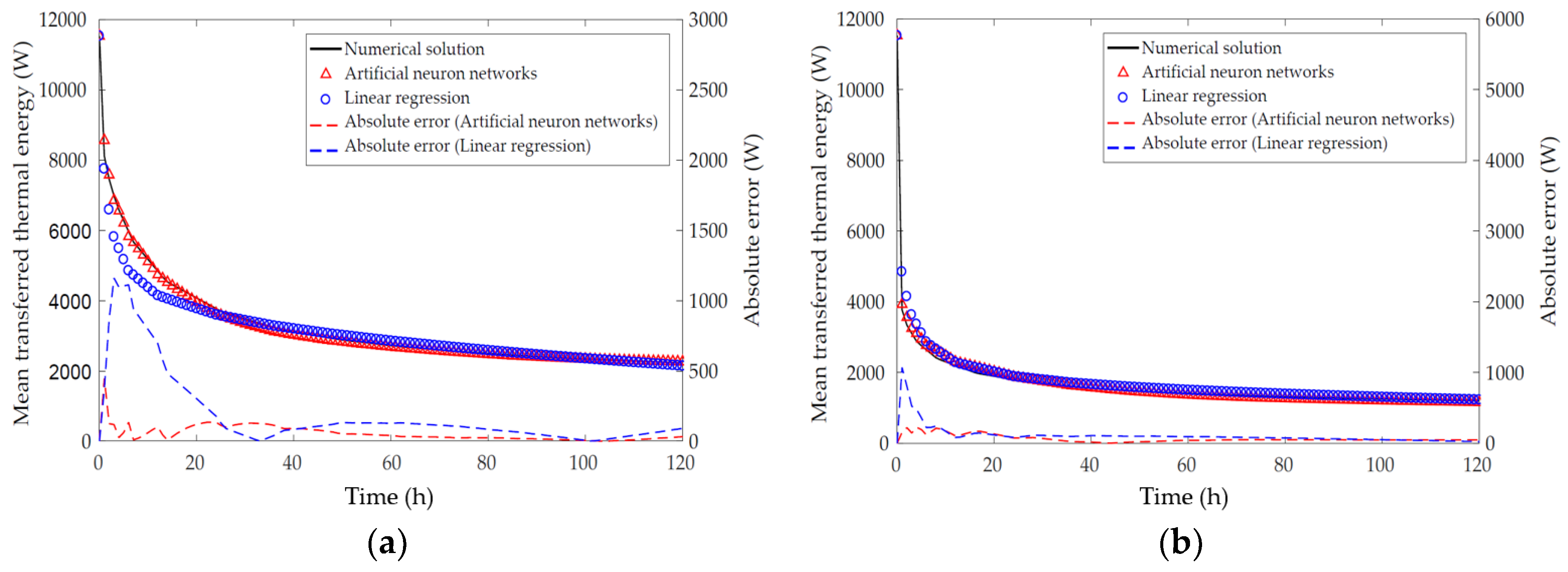
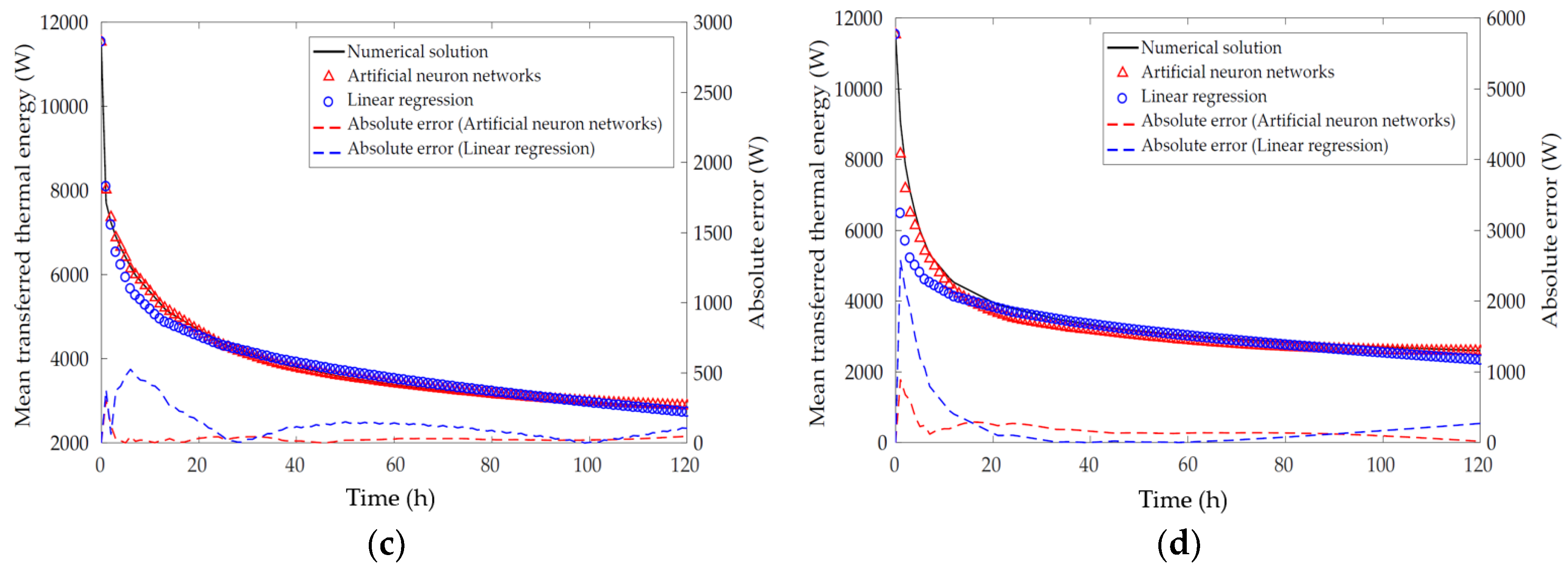
4.3. Validation of Proposed Models

The four cases listed in Table 7 were used for validation of the proposed models. Figure 12 shows the variation of the mean transferred thermal energy, which was calculated using scale factors obtained from the proposed models and the numerical solution. The mean transferred thermal energy for the spiral-coil-type GHE could be calculated by multiplying the scale factor with the mean transferred thermal energy for the straight-line-type GHE. The results of the ANN and linear regression models are in good agreement with the numerical solutions. However, the ANN model provided a more accurate prediction than the linear regression model because the ANN is generally utilized to generalize the nonlinear relationships.

5. Conclusions

In this study, the scale factor, which was defined by the ratio of the mean transferred thermal energy between the straight-line and spiral-coil-type horizontal GHEs, was investigated numerically. The effects of weather conditions, thermal properties of the ground, and the configuration of the spiral-coil-type ground heat exchanger were investigated in the parametric study, then scale factor models were suggested using an artificial neural network and a linear regression model. The following conclusions can be drawn from this study:
  • The effect of weather conditions on the scale factor is negligible because the maximum value of the average relative error was 0.507%.
  • The variation in the specific heat (from 560 J / ( kg · K ) to 1125 J / ( kg · K ) ) and density (from 1250 kg / m 3 to 2500 kg / m 3 ) has no influence on the performance of the horizontal ground heat exchanger if the volumetric heat capacity is identical.
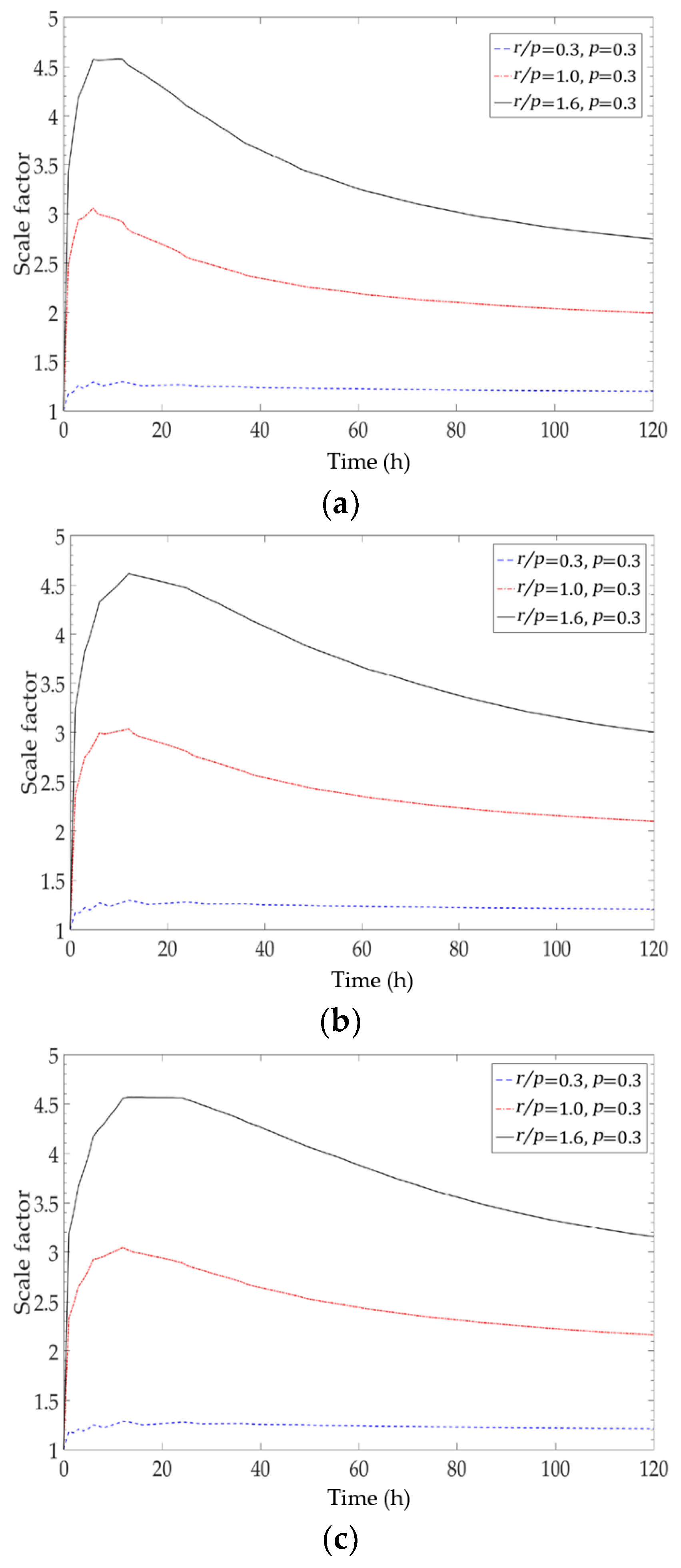
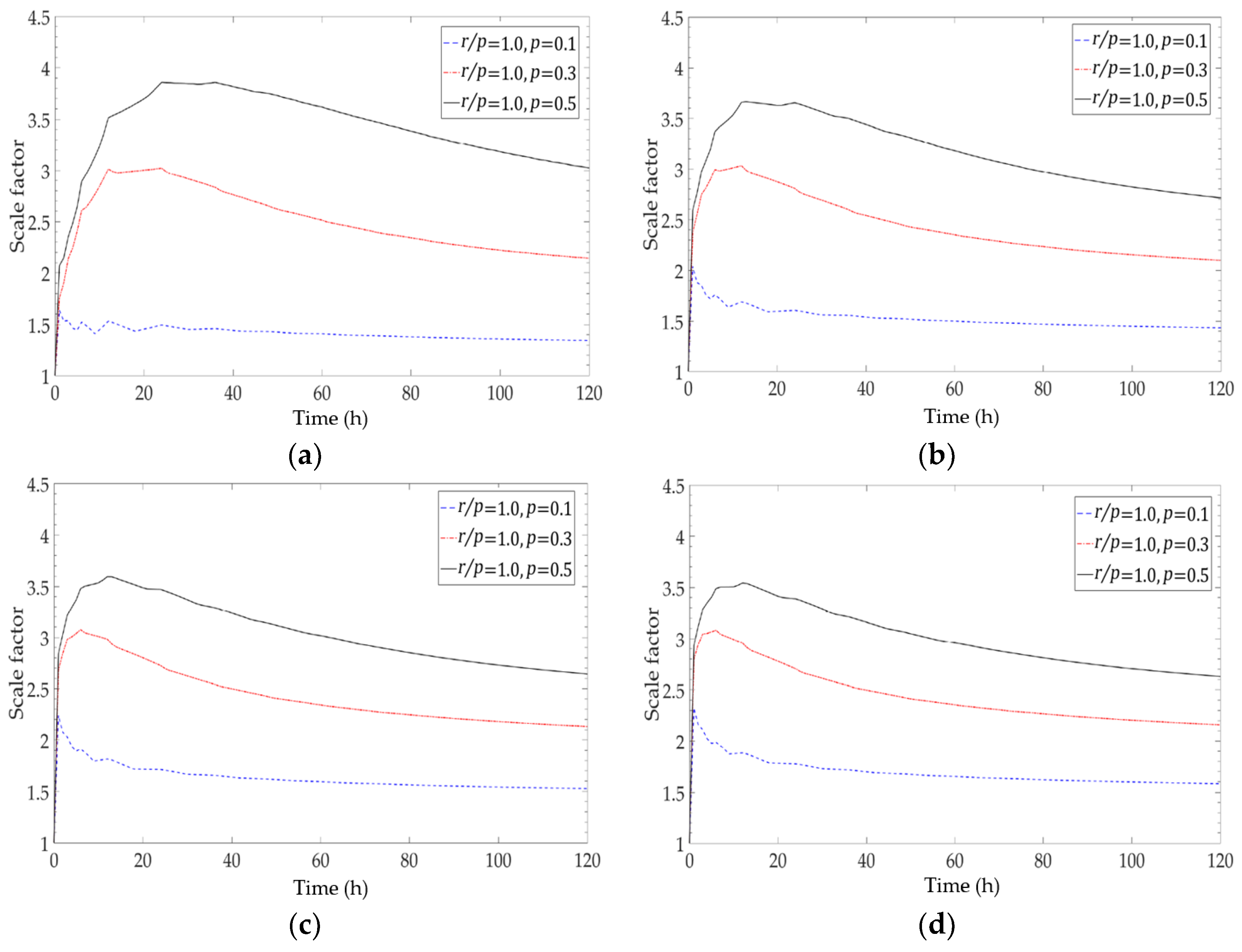
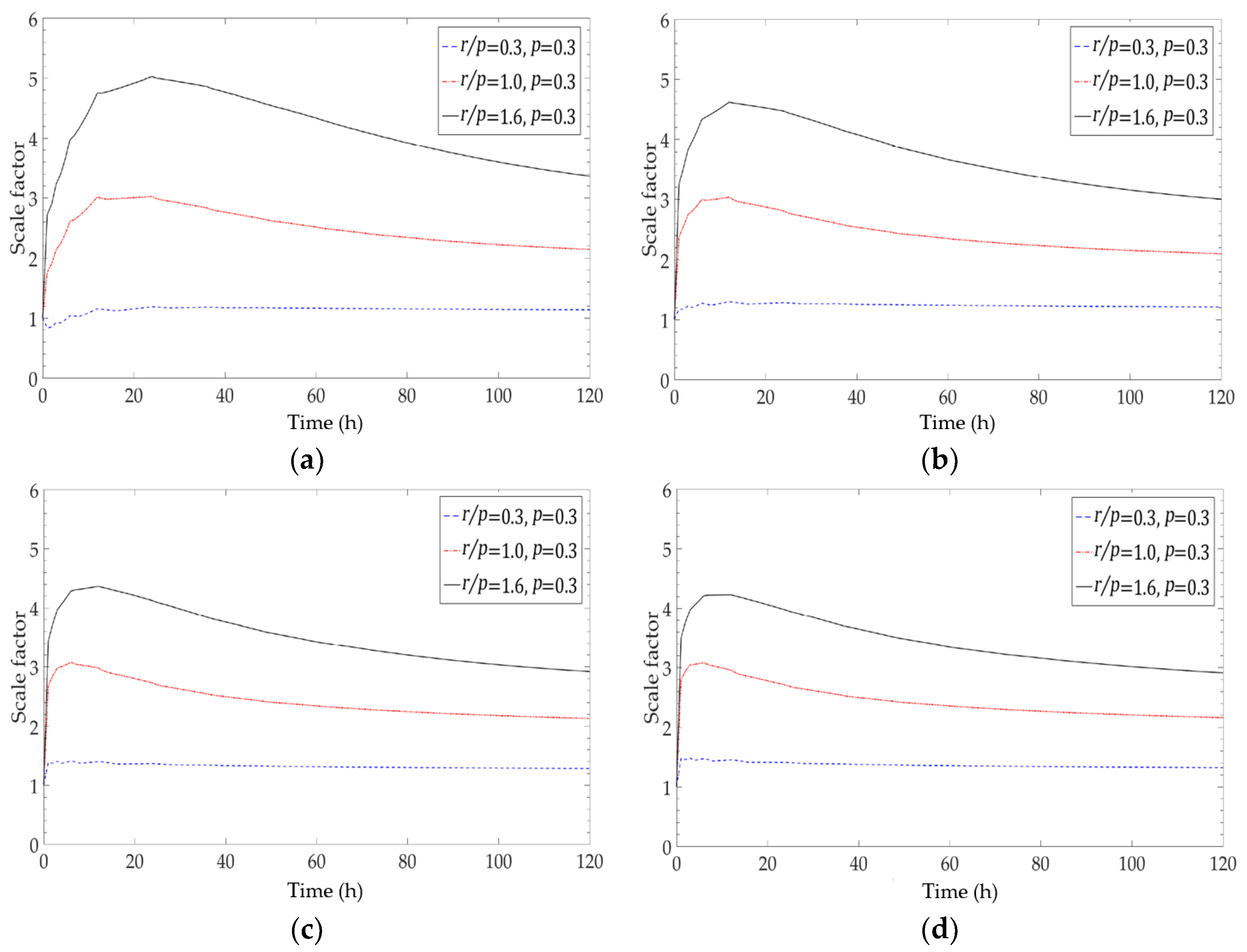
  • Depending on the specific ratio of the radius of the coil to the pitch size (approximately 1.0), the effect of the ground thermal properties (thermal conductivity and volumetric heat capacity) on the scale factor is different. As the thermal conductivity and the value of the product of the volumetric heat capacity and the thermal conductivity increase, the value of scale factor decreases when the ratio of the radius to pitch size is less than unity. The opposite trend is observed if the ratio is above unity. In addition, the correlation between the volumetric heat capacity and performance of the spiral-coil-type horizontal GHEs varies with time.
  • Different configurations (radius (from 0.1 to 0.5 m) and pitch size (from 0.1 to 0.5 m)) of the spiral-coil-type ground heat exchanger caused different heat transfer performances because of the different ground temperatures that developed surrounding the ground heat exchanger.
  • The main influence factors on the scale factor were determined to be the radius of the coil, pitch size, thermal conductivity of the ground, volumetric heat capacity, and time.
  • The results of the ANN and linear regression models are in good agreement with the numerical solutions. Due to the nonlinear relationship among the five factors, the ANN would be a more appropriate model than the linear regression model.
The scale factor model could provide an alternative way to estimate the trench length for the spiral-coil-type HGHEs based on the length of a straight-line-type HGHE. However, vulnerability still exists due to the simplification of the real ground conditions in the model development. For more accurate estimation of trench length for the spiral-coil-type HGHEs, the consideration of ground as porous medium and complex heat transfer phenomena through convection and advection should be considered in future studies.

Author Contributions

Conceptualization, J.-S.J.; Methodology, J.-S.J.; Software, J.-S.J. and M.-J.K.; Validation, J.-S.J.; Formal Analysis, J.-S.J. and S.Y.; Writing-Original Draft Preparation, J.-S.J.; Writing-Review & Editing, S.-R.L.; Supervision, S.-R.L.

Funding

This research received no external funding.

Conflicts of Interest

The authors declare no conflict of interest.

References

  1. United Nations. The Future We Want; Outcome Document of the United Nations Conference on Sustainable Development; United Nations: New York, NY, USA, 2012. [Google Scholar]
  2. Ali, M.H.; Kariya, K.; Miyara, A. Performance analysis of slinky horizontal ground heat exchangers for a ground source heat pump system. Resources 2017, 6, 56. [Google Scholar] [CrossRef]
  3. International Energy Agency. Renewable Energy Medium-Term Market Report 2015, 4th ed.; IEA: Paris, France, 2015. [Google Scholar]
  4. Stylianou, I.I.; Florides, G.; Tassou, S.; Tsiolakis, E.; Christodoulides, P. Methodology for estimating the ground heat absorption rate of ground heat exchangers. Energy 2017, 127, 258–270. [Google Scholar] [CrossRef]
  5. Kwon, K.S.; Lee, J.Y.; Mok, J.K. Update of current status on ground source heat pumps in Korea (2008–2001). J. Geo. Soc. Korea 2012, 48, 193–199. [Google Scholar]
  6. Adamovsky, D.; Neuberger, P.; Adamovsky, R. Changes in energy and temperature in the ground mass with horizontal heat exchangers—The energy source for heat pumps. Energy Build. 2015, 92, 107–115. [Google Scholar] [CrossRef]
  7. Florides, G.; Kalogirou, S. Ground heat exchangers—A review of systems, models and applications. Renew. Energy 2007, 32, 2461–2478. [Google Scholar] [CrossRef]
  8. Ameen, Y.A.; Ianakiev, A.; Evans, R. Recycling construction and industrial landfill waste material for backfill in horizontal ground heat exchanger systems. Energy 2018, 151, 556–568. [Google Scholar] [CrossRef]
  9. Simms, R.B.; Haslam, S.R.; Craig, J.R. Impact of soil heterogeneity on the functioning of horizontal ground heat exchangers. Geothermics 2014, 50, 35–43. [Google Scholar] [CrossRef]
  10. Demir, H.; Koyun, A.; Temir, G. Heat transfer of horizontal parallel pipe ground heat exchanger and experimental verification. Appl. Therm. Eng. 2009, 29, 224–233. [Google Scholar] [CrossRef]
  11. Neupauer, K.; Pater, S.; Kupiec, K. Study of ground heat exchangers in the form of parallel horizontal pipes embedded in the ground. Energies 2018, 11, 491. [Google Scholar] [CrossRef]
  12. Sangi, R.; Muller, D. Dynamic modelling and simulation of a slinky-coil horizontal ground heat exchanger using Modelica. J. Build. Eng. 2018, 16, 159–168. [Google Scholar] [CrossRef]
  13. Wu, Y.; Gan, G.; Verhoef, A.; Vidale, P.L.; Gonzalez, R.G. Experimental measurement and numerical simulation of horizontal-coupled slinky ground source heat exchangers. Appl. Therm. Eng. 2010, 30, 2574–2583. [Google Scholar] [CrossRef] [Green Version]
  14. Fujii, H.; Nishi, K.; Komaniwa, Y.; Chou, N. Numerical modeling of slinky-coil horizontal ground heat exchangers. Geothermics 2012, 41, 55–62. [Google Scholar] [CrossRef]
  15. Fujii, H.; Yamasaki, S.; Maehara, T.; Ishikami, T.; Chou, N. Numerical simulation and sensitivity study of double-layer slinky-coil horizontal ground heat exchangers. Geothermics 2013, 47, 61–68. [Google Scholar] [CrossRef]
  16. Chong, C.S.A.; Gan, G.; Verhoer, A.; Garcia, R.G.; Vidale, P.L. Simulation of thermal performance of horizontal slinky-loop heat exchangers for ground source heat pump. Appl. Energy 2013, 104, 603–610. [Google Scholar] [CrossRef]
  17. Dasare, R.R.; Saha, S.K. Numerical study of horizontal ground heat exchanger for high energy demand applications. Appl. Therm. Eng. 2015, 85, 252–263. [Google Scholar] [CrossRef]
  18. Congedo, P.M.; Colangelo, G.; Starace, G. CFD simulations of horizontal ground heat exchangers: A comparison among different configurations. Appl. Therm. Eng. 2012, 33–34, 24–32. [Google Scholar] [CrossRef]
  19. Kim, M.J.; Lee, S.R.; Yoon, S.; Go, G.H. Thermal performance evaluation and parametric study of a horizontal ground heat exchanger. Geothermics 2016, 60, 134–143. [Google Scholar] [CrossRef]
  20. Kim, M.J.; Lee, S.R.; Yoon, S.; Jeon, J.S. An applicable design method for horizontal spiral-coil-type ground heat exchangers. Geothermics 2018, 72, 338–347. [Google Scholar] [CrossRef]
  21. Jeon, J.S.; Lee, S.R.; Kim, M.J. A modified mathematical model for spiral coil-type horizontal ground heat exchangers. Energy 2018, 152, 732–743. [Google Scholar] [CrossRef]
  22. Gaia Geothermal Group. Ground Loop Design Software. 2014. Available online: https://www.gaiageo.com (accessed on 9 July 2018).
  23. School of Mechanical and Aerospace Engineering, Oklahoma State University. GLHEPro 5.0 for Windows Users’ Guide; International Ground Source Heat Pump Association: Stillwater, OK, USA, 2016. [Google Scholar]
  24. Kavanaugh, S.P.; Rafferty, K. Ground-Source Heat Pumps and Design of Geothermal Systems for Commercial and Institutional Buildings; ASHRAE: Atlanta, GA, USA, 1997. [Google Scholar]
  25. Jeon, J.S.; Lee, S.R. Suggestion of a load sharing ratio for the design of spiral coil-type horizontal ground heat exchangers. Energy Procedia 2017, 141, 292–298. [Google Scholar] [CrossRef]
  26. Naylor, S.; Ellett, K.M.; Gustin, A.R. Spatiotemporal variability of ground thermal properties in glacial sediments and implications for horizontal ground heat exchanger design. Renew. Energy 2015, 81, 21–30. [Google Scholar] [CrossRef] [Green Version]
  27. Selamat, S.; Miyara, A.; Kariya, K. Numerical study of horizontal ground heat exchangers for design optimization. Renew. Energy 2016, 95, 561–573. [Google Scholar] [CrossRef]
  28. Leong, W.H.; Tarnawski, V.R.; Aittomaki, A. Effect of soil type and moisture content on ground heat pump performance. Int. J. Refrig. 1998, 21, 595–606. [Google Scholar] [CrossRef]
  29. Naili, N.; Hazami, M.; Attar, I.; Farhat, A. In-field performance analysis of ground source cooling system with horizontal ground heat exchanger in Tunisia. Energy 2013, 61, 319–331. [Google Scholar] [CrossRef]
  30. Kusuda, T.; Achenbachm, R.S. Earth temperatures and thermal diffusivity at selected stations in the United States. ASHRAE Trans. 1965, 71, 61–74. [Google Scholar]
  31. Xing, L. Estimations of Undisturbed Ground Temperatures Using Numerical and Analytical Modeling. Ph.D. Thesis, Oklahoma State University, Stillwater, OK, USA, December 2014. [Google Scholar]
  32. Zarrella, A.; Emmi, G.; Carli, M.D. Analysis of operating modes of a ground source heat pump with short helical heat exchangers. Energy Convers. Manag. 2015, 97, 351–361. [Google Scholar] [CrossRef]
  33. Zhao, Q.; Chen, B.; Liu, F. Study on the thermal performance of several types of energy pile ground heat exchangers: U-shaped, W-shaped and spiral-shaped. Energy Build. 2016, 113, 335–344. [Google Scholar] [CrossRef]
  34. Luo, J.; Zhao, H.; Gui, S.; Xiang, W.; Rohn, J.; Blum, P. Thermo-economic analysis of four different types of ground heat exchangers in energy piles. Appl. Therm. Eng. 2016, 108, 11–19. [Google Scholar] [CrossRef]
  35. Dehghan, B.B. Experimental and computational investigation of the spiral ground heat exchangers for ground source heat pump applications. Appl. Therm. Eng. 2017, 121, 908–921. [Google Scholar] [CrossRef]
  36. Hepburn, B.D.P.; Sedighi, M.; Thomas, H.R.; Manju. Field-scale monitoring of a horizontal ground source heat system. Geothermics 2016, 61, 86–103. [Google Scholar] [CrossRef]
  37. Gonzalez, R.G.; Verhoef, A.; Vidale, P.L.; Main, B.; Gan, G.; Wu, Y. Interactions between the physical soil environment and a horizontal ground coupled heat pump for a domestic site in the UK. Renew. Energy 2012, 44, 141–153. [Google Scholar] [CrossRef]
  38. Busby, J. Determination of thermal properties for horizontal ground collector loops. In Proceedings of the World Geothermal Congress, Melbourne, Australia, 19–25 April 2015. [Google Scholar]
  39. Sipio, E.D.; Bertermann, D. Factors Influencing the thermal efficiency of horizontal ground heat exchangers. Energies 2017, 10, 1897. [Google Scholar] [CrossRef]
  40. Kim, Y.S.; Do, T.M.; Kim, M.J.; Kim, B.J.; Kim, H.K. Utilization of by-product in controlled low-strength material for geothermal systems: Engineering performances, environmental impact, and cost analysis. J. Clean. Prod. 2018, 172, 909–920. [Google Scholar] [CrossRef]
  41. Hagan, M.T.; Demuth, H.B.; Beale, M. Neural Network Design; PWS Publishing Company (a Division of International Thomson Publishing Inc.): Boston, MA, USA, 1996. [Google Scholar]
  42. Beale, M.H.; Hagan, M.T.; Demuth, H.B. Neural Network ToolboxTM User’s Guide (2016a); The MathWorks, Inc.: Natick, MA, USA, 2016. [Google Scholar]
Figure 1. Schematic view of the numerical simulation model.
Energies 11 02736 g001
Figure 2. Schematic diagram of a spiral-coil-type horizontal ground heat exchanger (HGHE) considered in the parametric study.
Energies 11 02736 g002
Figure 3. Variations in the scale factor for the weather conditions.
Energies 11 02736 g003
Figure 4. Mean transferred thermal energy calculated for nine cases having different thermal properties of the ground. (a) Case 1–3; (b) Case 4–9.
Energies 11 02736 g004
Figure 5. Scale factors by different radii and pitch sizes of spiral coil for Case A: blue (low k g ), red (medium k g ), and yellow (high k g ).
Energies 11 02736 g005
Figure 6. Scale factors by different radii and pitch sizes of spiral coil for Case B: blue (low C p , g · ρ g · k g ), red (medium C p , g · ρ g · k g ), and black (high C p , g · ρ g · k g ).
Energies 11 02736 g006
Figure 7. Scale factor by different volumetric heat capacities when the thermal conductivity is 1.5 W / ( m · K ) . (a) C p , g · ρ g = 1125   kJ / m 3 · K ; (b) C p , g · ρ g = 1800   kJ / m 3 · K ; (c) C p , g · ρ g = 2250   kJ / m 3 · K .
Energies 11 02736 g007
Figure 8. Effect of the pitch size with identical ratios of the coil radius and pitch size. (a) k g = 0.7   W / ( m · K ) ; (b) k g = 1.5   W / ( m · K ) ; (c) k g = 2.4   W / ( m · K ) ; (d) k g = 3.0   W / ( m · K ) .
Energies 11 02736 g008
Figure 9. Effect of the coil radius with an identical pitch size. (a) k g = 0.7   W / ( m · K ) ; (b) k g = 1.5   W / ( m · K ) ; (c) k g = 2.4   W / ( m · K ) ; (d) k g = 3.0   W / ( m · K ) .
Energies 11 02736 g009
Figure 10. Architecture of artificial neural networks in this study.
Energies 11 02736 g010
Figure 11. Regression plots of the proposed ANN model.
Energies 11 02736 g011
Figure 12. Comparison of the mean transferred thermal energies obtained using numerical solution and proposed models. (a) Case 1; (b) Case 2; (c) Case 3; (d) Case 4.
Energies 11 02736 g012aEnergies 11 02736 g012b
Table 1. Values of considered factors used in the parametric study.
FactorsUnitValues
Weather conditionsAnnual average soil temperature, T a v g °C16, 18, 20
Annual amplitude of the surface temperature, A s °C5, 10, 15
Configuration of GHEPitch size of coil, p m0.1, 0.3, 0.5
Radius of coil, r m0.1, 0.3, 0.5
Thermal properties of the ground (including backfill material)Thermal conductivity, k g W / ( m · K ) 0.7, 1.5, 2.4, 3.0
Specific heat capacity, C p , g J / ( kg · K ) 560, 780, 900, 1060, 1125
Density, ρ g kg / m 3 1250, 1700, 2000, 2300, 2500
TimeOperation time, t hUp to 120
Table 2. All cases considered for the effect of weather conditions.
Case Annual   Average   Soil   Temperature ,   T a v g (°C) Annual   Amplitude   of   the   Surface   Temperature ,   A s (°C)
1165
2185
3205
41610
51810
62010
71615
81815
92015
Table 3. Relative error (RE) of scale factor for each case with respect to Case 4.
RE (%)Case 1Case 2Case 3Case 4Case 5Case 6Case 7Case 8Case 9
Maximum0.8650.8651.327-1.6461.0551.5610.9111.816
Minimum0.0050.0050.0001-0.0010.0020.0010.0310.016
Average0.1810.1810.222-0.2510.1300.2330.2140.507
Table 4. Thermal properties of ground for parametric study.
Case Specific   Heat ,   C p , g
( J / ( k g · K ) )
Density ,   ρ g
( k g / m 3 )
Thermal   Conductivity ,   k g
( W / ( m · K ) )
Volumetric   Heat   Capacity ,   C p , g · ρ g
( k J / ( K · m 3 ) )
1106017002.41800
290020002.41800
378023002.41800
456020001.51125
590020002.41800
6112520003.02250
790012501.51125
890020002.41800
990025003.02250
Table 5. Cases for the effect of the spiral coil configuration.
Case Radius / Pitch   Size ,   r / p
(−)
Pitch   Size ,   p
( m )
11.00.1
23.00.1
35.00.1
40.30.3
51.00.3
61.60.3
70.20.5
80.60.5
91.00.5
Table 6. Results of the linear regression model.
PredictorsEstimated Coefficientsp-Value
Intercept0.560626.8885 × 10 310
k g 0.23450
C p , g · ρ g 7.2827 × 10 8 1.599 × 10 25
p −0.690994.0214 × 10 127
r 7.85010
t −0.00109385.0834 × 10 50
k g · C p , g · ρ g −1.9364 × 10 8 9.4257 × 10 18
k g · p −0.0621232.4986 × 10 22
C p , g · ρ g · p −3.5181 × 10 7 5.7443 × 10 181
k g · r −0.726330
C p , g · ρ g · r 9.2097 × 10 7 0
p · r −2.52570
p · t 0.00921010
r · t −0.027120
Table 7. Validation for the proposed models.
Case Thermal   Conductivity ,   k g
( W / ( m · K ) )
Volumetric   Heat   Capacity ,   C p , g · ρ g
( k J / ( K · m 3 ) )
Pitch   Size ,   p
( m )
Radius ,   r
( m )
11.813500.20.3
21.221600.30.3
32.619200.30.3
42.911700.10.2

