Highly Efficient Target Power Control for Two-Receiver Wireless Power Transfer Systems


Key Laboratory of Control of Power Transmission and Transformation Ministry of Education, Shanghai Jiao Tong University, 800 Dongchuan RD., Shanghai 200240, China
*
Authors to whom correspondence should be addressed.
Energies 2018, 11(10), 2726; https://doi.org/10.3390/en11102726
Submission received: 19 August 2018
/
Revised: 6 October 2018
/
Accepted: 8 October 2018
/
Published: 11 October 2018
Abstract
:Multiple-receiver wireless power transfer (MRWPT) systems have revolutionary potential for use in applications that require transmitting power to multiple devices simultaneously. In most MRWPT systems, impedance matching is adopted to provide maximum efficiency. However, for most MRWPT systems, achieving target power levels and maximal efficiency is difficult because the target output power and maximum efficiency conditions are mostly not satisfied. This study establishes a target power control (TPC) strategy to balance providing target transfer powers and operating under high efficiency. This study is divided into the following points: First, this study derives the optimal mutual inductance to verify that it’s difficult for two-receiver wireless power transfer (WPT) system to achieve both maximum efficiency and power distribution simultaneously; Second, this study illustrates that for impedance matching method the mutual inductances play a more important role than equivalent impedances in increasing the system efficiency, and hence system should give priority in improving the mutual inductance as large as possible; Third, this study proposes a simplified system model which helps to derive the analytic solutions of equivalent impedances; Fourth, this study developed a 100-kHz two-receiver WPT system and establishes a TPC strategy for enabling the system to achieve target output power levels with high efficiency; At last, the proposed system is proved to achieve an efficiency level of more than 90 % and satisfies the target output power levels requirements.
1. Introduction
Wireless power transfer (WPT) is a promising technology that has attracted increasing attention in industry and academia. WPT has been applied to biomedical implants [1,2,3,4], underwater power supply systems [5,6], mining equipment [7,8], logistic robots [9], and electronic equipment [7]. The advantages of WPT are as follows: convenience, security, and robustness against complex environments and objects such as water and skin.
With the development of WPT technology, demands for embedding electrical devices in a WPT system are increasing. Devices incorporated into a WPT system mostly operate with distinct load characteristics and power levels. For achieving high system efficiency and satisfying different load characteristics, further researches should be conducted on multiple-receiver wireless power transfer (MRWPT) technology
In a WPT system, maximum power transfer efficiency is achieved when the load resistance satisfies the impedance matching method [10]. To improve system efficiency, various methodologies and topologies have been developed. The optimal loads have been analyzed for an MRWPT system and a buck circuit introduced for achieving the optimal loads [11]. The measured maximum efficiency is 80% when system operates at 13.56 MHz. However, the output power could not be controlled because the system must satisfy the optimal loads. The conventional WPT system introduces an uncontrolled rectifier to transform AC voltage into DC voltage; this approach can easily ensure that the AC voltage at the receiver coil has the same phase as the AC current, but it also introduces relatively large power loss due to the voltage drop of the diodes. A buck-boost converter [12] is introduced to the rectifiers to optimal the load resistance. The measured maximum efficiency is 78% when system transfers 16 W. Phase-shifting and an amplitude control method [13] are employed to manipulate the equivalent load resistance for improving system efficiency. The maximum measured efficiency is 36% with a factor k = 0.6 and even 83% with a factor k = 0.3. In [14], a buck converter is introduced to the primary-side to regulate input power and a boost converter is introduced to the secondary-side to optimize the load. The measured maximum efficiency is 79% when the system transfers 100 W. A multiple-coil WPT system is analyzed and the optimal resistance is calculated for a relatively high power supply efficiency in [15]. Other studies [16,17] have introduced a dual-active-bridge control system to replace the uncontrolled rectifier. Such a converter has the advantage of an extremely small conduction resistance, which increases system efficiency and provides optimal loads. An improved efficiency of 85.4% with a 468.6 W output power is achieved in [16], while [17] realizes an efficiency of 80.4% when delivering 18 W power at a distance of 21 cm. Furthermore, it can compensate the imaginary reactance component in receiver coils when frequency changes. From above studies, these topologies contribute to load optimization and help to enhance the efficiency. However, these methodologies introduce additional segments and raise extra losses like DC-DC converters. Further discussions of finding effective and efficient topologies with fewer converters and component losses should be considered.
Regarding power distribution of MRWPT system, the main problems are the independent control of each receiver and eliminating the cross-coupling influences. An approach is developed for providing constant voltage for a MRWPT system [18]. To control the power of receiver coils, Fu et al. [18] introduced a buck circuit to change the output power; however, introducing this topologies added an extra segment to the system, thus increasing the system’s power loss. Besides, Power distribution is examined by applying coupled-mode theory to provide the required amount of power [19], thus improving the efficiency of the entire system. The mentioned study also derived an optimal matching condition and obtained the maximum system efficiency; however, the study analyzed the system using coupled-mode theory, and applying its findings to practical applications is difficult. Besides, cross-coupling adds additional reactors to the receivers’ circuit and hence enhances the complexity of power distribution. Concerning eliminating the cross-coupling problems, Buck converters are introduced to each receiver circuit to optimal the load resistances and control the power distribution [11]. A time-division multiplexing method [20] is employed to simultaneously manage the power flow and eliminate the cross-coupling problem. Cross coupling between multiple receivers is compensated and analyzed and optimized system operating procedures [21]. The study compared the original efficiency and power distribution of a dual-receiver system with the efficiency and power distribution obtained after compensation; subsequently, the study extended the theory to a multiple-receiver system. However, the power distribution methodologies above introduce additional losses due to the complex circuit structure and additional converters. Further work on balancing the power distribution and efficiency enhancement is required.
Nowadays, the impedance matching method is still an important method to derive the maximal efficiency of a WPT system. However, the impedance matching method has difficulties in providing target transfer powers. The TPC method is proposed in this study to solve this problem. This study established a control strategy for providing the target output power of two-receiver WPT system, thus ensuring low system power consumption and high system efficiency, which is suitable for practical applications involving multiple loads. The proposed control method is based on a simplified model which approaches the ideal model for practical applications. In the proposed MRWPT system, controlling the mutual inductances and coil parameters is difficult; therefore, achieving both maximal efficiency and target output power levels is impractical in such system. Furthermore, because mutual inductance plays a major role in improving system efficiency, the proposed control strategy maintains the maximal mutual inductances and controls the equivalent impedance levels to achieve the target output power levels. For achieving an equivalent impedance level based on a target output power level, analytic solutions of equivalent impedance levels cannot be solved due to the complex calculation process. The current study solved this problem by introducing a simplified system model to achieve an analytic solution approximating the actual solution. This paper also describes the design and implementation of a two-receiver WPT system involving an active-bridge control strategy applied at the receiver coils. This paper is organized as follows: Section 2 explains the basic design, introduces the system circuit model. Section 3 presents the system simplification, and the TPC method based on simplified model. In Section 4, the phase manipulation and system flowchart are presented, and Section 5 presents the experimental results. The conclusions are provided in Section 6.
2. Modeling of Two-Receiver WPT System
2.1. Circuit Model of Two-Receiver WPT System
This section describes a two-receiver WPT system involving inductive coupling. Because the system comprises different coils with dissimilar target power levels, the traditional uncontrolled rectifier cannot control the output power of each receiver coil. A control strategy must be developed for each receiver coil to ensure that each coil receives its target power. Therefore, the system includes an active-bridge control strategy and SS compensation topology to manipulate the output power.
Figure 1 presents the schematic and equivalent circuits of the proposed two-receiver WPT system. In Figure 1a, coil 1 is the transmitter coil and coils 2 and 3 are the receiver coils. The solid and dotted arrows denote mutual inductances between coils, and the red dotted box denotes the impedance matching segments. L1, L2, and L3 represent the self-inductance of the coils. Ri, Li, and Ci (i = 1, 2, 3) denote the resistance, inductance, and compensation capacitance of the coils, respectively. Q1~Q12 are the drive signals of the converters.
Figure 1b illustrates the equivalent circuit of the two-receiver WPT system. Zeq2 and Zeq3 represent the equivalent impedance of the impedance matching segment. U1f denotes the fundamental component of the inverter voltage U1. By performing the Fourier decomposition of voltage U1, the fundamental component U1f is derived in (1):
where Uin denotes the input DC voltage, 2β1 denotes the conduction angle of the transmitter coil of the system, and denotes the phase of the fundamental component of the input square wave.
Using the Kirchhoff Voltage Laws (KVLs), the equivalent mathematical model of the two-receiver WPT system can be obtained as follows:
Because the distance between the two receiver coils is greater than the distance between the transmitter coil and the receiver coils in the proposed system, the mutual inductance M23 between the two receiver coils can be neglected (i.e., M23 = 0). In the two-receiver WPT system, when the receivers operate at the resonant frequency, at which the system satisfies (3) the equivalent mathematical model (2) can be simplified to yield (4). Regarding (4), because the self-inductances and capacitances are compensated, there is no need for the imaginary parts of Zeq2 and Zeq3 to compensate the self-inductances and capacitances, that is Xeq2 = Xeq3 = 0, Zeq2 = Req2 and Zeq3 = Req3:
The system efficiency η is defined as follows:
Solving (4) and substituting the results into (5) can yield the efficiency η as follows:
According to the efficiency calculation, when the system operates at the resonant frequency (3), L1 and C1 are not relevant to the efficiency. Moreover, η is a function of the mutual inductance, operating frequency, coil resistance, and equivalent impedance. For practical applications, changing the mutual inductance and coil resistance is difficult, and the operating frequency must satisfy (3); hence, to reduce the complexity of the control strategy, the equivalent impedance should be tuned to control system efficiency.
2.2. Impedance Matching Control
In this section, impedance matching control is adopted to derive the optimal equivalent for two-receiver WPT system. To maximize the efficiency η of the system, the equivalent impedance should be optimized. For a maximum η, the optimal matching impedance Req2 and Req3 can be calculated by taking the first-order partial derivative of η, and then it yields:
The output active power levels of coils 2 and 3 are presented as follows:
Substituting (8) into (4) and (7) yields the following:
According to the derived equation of efficiency η, when the system operates under a fixed circuit parameter and the impedance matching segment satisfies the best matching condition presented in (7), the output power of the two receiver coils will satisfy (10):
Under the strict conditions presented in (10), the output power levels of the two receiver coils may not satisfy the target output power. However, for most applications, the target output power must be designed to satisfy system requirements. The following section further discusses the control strategy used for balancing the efficiency and target output power of the system.
2.3. Optimal Mutual Inducatance Based on Impedance Matching Control
In this section, the optimal mutual inductances are calculated to provide target power, and it illustrates that it is difficult for impedance matching technique to provide the target power. Suppose that the losses in the impedance matching segment are neglected and that the three coils satisfy the resonant condition , (i = 1, 2, 3). Based on Figure 1b, the output power levels P2 and P3 can be derived as follows:
Regarding the best matching condition for resistance presented in (7), the desired mutual inductances M12opt and M13opt at a target output power and best resistance can be derived as:
where the user-defined parameters A and B satisfies:
The derived equations signify that if the system operates under the best impedance matching condition, resonant condition, and target output power condition, M12, OPT and M13, OPT must strictly satisfy (12). Obviously, . However, in practice, achieving the desired M12, OPT and M13, OPT is difficult because of the nonlinearity between mutual inductance and the distances between coils. Although the system can manipulate β1 to control the output power, the output power ratio P2/P3 is relevant to the mutual inductance. Thus, the next section discusses the control strategy for conditions under which the desired mutual inductances are inadequate.
3. Target Power Control
3.1. Simplified Model
Deriving the partial derivative of efficiency η with respect to M12 and M13 yields the following:
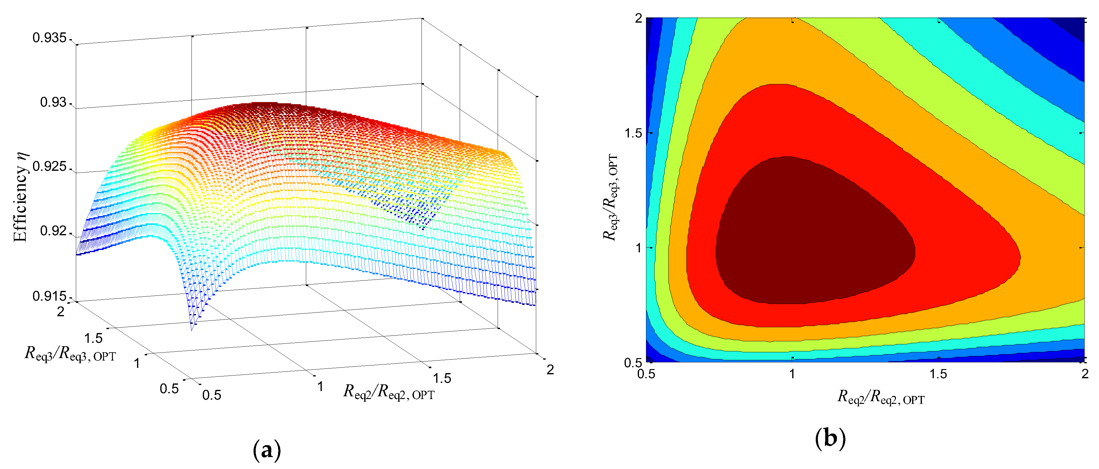
According to (13), system efficiency increases with M12 and M13 increasing. In addition, Figure 2 and Figure 3a reveal that system efficiency increases with the mutual inductance and equivalent impedance levels. Thus, for practical applications, achieving sufficiently high M12 and M13 in the system is more important than achieving matching resistance levels. Accordingly, in general scenarios, maximizing mutual inductance is prioritized in system design processes, followed by optimizing matching resistance levels. However, in such scenarios, the mutual inductance cannot satisfy (12) for achieving high system efficiency.
Figure 2 illustrates that when the mutual inductance increases, the efficiency of the system increases, and the output power increases accordingly. To ensure that the system output power satisfies a user’s need, the efficiency of the system must be sacrificed to meet the target output requirement.
Assume that the transmitter coil operates under the resonant condition; that is, jωL1 + 1/ωC1 = 0. In general, for coils, the equivalent resistance Reqi (i = 2, 3) is considerably higher than the parasitic resistance Ri (i = 2, 3). For simplicity, (11) can be simplified as follows:
On the basis of (14), the equivalent impedances Req2 and Req3 can be derived according to P2 and P3 as follows:
In the preceding derivation, P2 and P3 can be represented by Req2 and Req3, respectively, which simplifies the calculation process and connects the output power with the impedance matching segment. Thus, by manipulate the equivalent impedance, the target output power can be easily achieved. The actual output power levels P2, SIMP and P3, SIMP under the condition of (14) can be expressed as follows:
When the mutual inductance improves, the output error generated by the approximation of (11) decreases and can be neglected. Therefore, (14) can replace (11) for simplicity in general scenarios.
As reported by a previous study [17], the equivalent impedance of the impedance matching segment can be expressed as follows:
The imaginary component of the impedance matching segment should be zero due to the resonance condition presented in (3). Therefore, according to the preceding equation, the maximum real value of can be derived as follows:
To ensure receivers can provide the target power levels P2 and P3, the maximum should satisfy the following condition:
3.2. Target Power Control
In the proposed system, the receiver coils control the target output power and the transmitter coil ensures optimal system efficiency. When the system operates under the best impedance matching condition and a constant mutual inductance, the optimal U1 provides the highest efficiency.
Figure 3 reveals the efficiency when the equivalent resistance ratio Reqi/Reqi, OPT of the resistance matching segment increases, however, because the equivalent resistances must be controlled to produce the target power, the impedance matching segment cannot be set randomly. To solve this problem, U1 can be regulated to achieve high system efficiency and the receiver coils can be controlled to reach the target output power. According to (6), the input voltage U1 is not relevant to the system’s efficiency, but to ensure that the system achieves the target power, the equivalent resistance is relevant to U1; hence, the optimization of U1 must be considered. U1 can thus be modified to change the power transferred to the receiver coils and the equivalent resistance must be manipulated accordingly to ensure a target output power.
When the mutual inductance is fixed, U1 and the two equivalent output resistance levels can be controlled simultaneously to achieve optimal efficiency.
Substituting (15) into (6) yields the approximate efficiency ηSIMP. To solve , the following condition can be considered: when U1 satisfies (19), the system achieves optimal efficiency:
4. Phase Manipulation and Flowchart
As mentioned, the phase between the voltage and current at the receiver coils can be controlled using the impedance matching segment. The active bridges of receivers can control the equivalent output resistance and output power by manipulating the impedance matching segment; however, this approach also affects system efficiency. Further research on the control strategy is necessary.
4.1. Phase Manipulation
This section describes the phase operation of the transmitter and receivers. When the receiver coils operate under the resonant condition, the phases of the voltage and current at the transmitter coil do not affect the system’s efficiency, according to (6). Additionally, the reflected resistance of the receiver coils is a real number, according to (20):
where Rreflect2 and Rreflect3 represent the reflected resistances of the receiver coils.
If the transmitter coil does not operate under the resonant condition, changes in the equivalent impedances Zeqi engender changes in reflected resistances Zreflecti and changes in the phases of I1, I2, and I3. Hence, the phase of the receiver coils must be readjusted accordingly, and this necessity introduces further control complexity and instability to the system.
If the transmitter coil operates under the resonant condition, the phases of U1 and I1 are zero. When the impedance matching segment changes, the phases of the receiver coils remain unchanged, and manipulating the phases of the receiver coils is unnecessary. Therefore, the system is required to conduct phase manipulation only once, and the phases subsequently remain unchanged regardless of changes in the impedance matching segment.
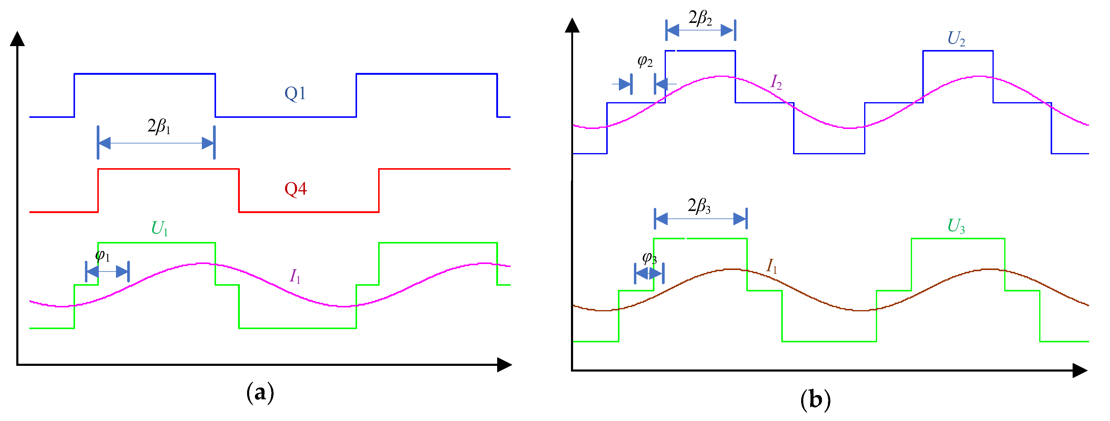
Figure 4 illustrates the drive signals, square-wave voltages and resonant currents waveforms in SS WPT system. Driver signal Q1, Q4 is derived by phase-shifting controlled converter with shift phase (π − 2β1). φi is the phase between the fundamental component of Ui and converter current Ii (i = 1, 2, 3). When system operates under the resonant condition and system satisfies φi = 0, (i = 2, 3), the reflect resistance Zreflecti will be a real value, and hence φ1 = 0. Therefore, Ii, (i =1, 2, 3) are of the same phase as the fundamental component of converter voltage Uif (i =1, 2, 3) regardless of the change of Zeqi,
4.2. Flowchart
This section describes the general flowchart of system control aimed at achieving high efficiency and target output power levels. The discussion demonstrates that when the system is launched, the system should be manipulated to operate under the resonant condition, and the phases of the voltage and current should be the same. Figure 5 illustrates the flowchart of system control process. Before the system is launched, the appropriate Li Ci and frequency ω must be selected to ensure that the receiver coils operate under the resonant condition. Subsequently, M12opt and M13opt can be calculated using (16). The system can then be started and β1, β2, and β3 can be initialized; the conduction angle of the transmitter coil can be controlled to transfer a small input power to the receiver coils in order to control the phase between the voltage and current at the receiver coils. The PWM wave of the receiver coils can be shifted to ensure that the voltages U2 and I2 and U3 and I3 are of the same phase. U1 can be increased, and β2 and β3 can be manipulated concurrently to ensure that the desired output power is achieved.
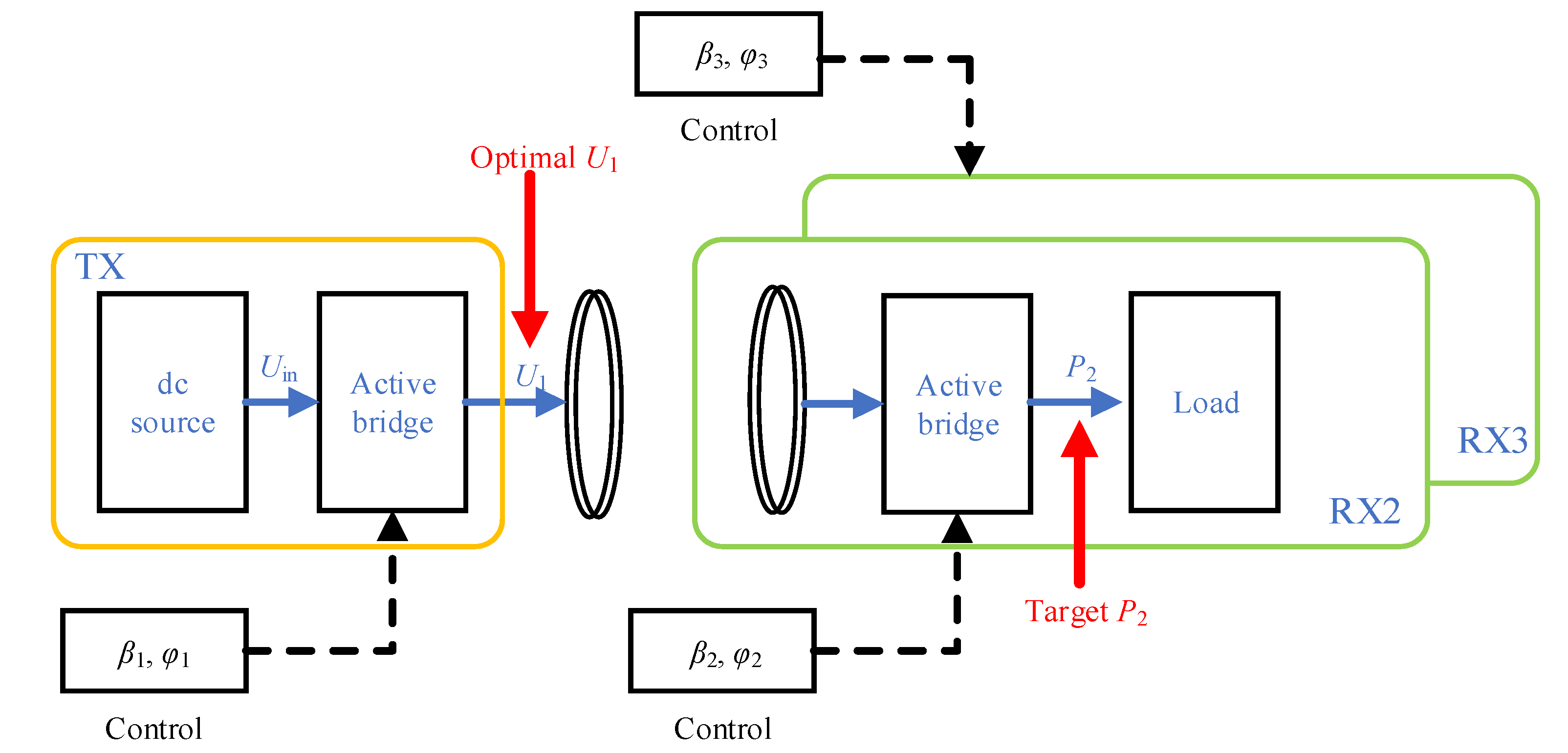
Figure 6 illustrates the two-receiver WPT system configuration and the control method. TX denotes the transmit coil and RX2 and RX3 denote the receive coil. For achieving highly efficient target power, β1 and φ1 are manipulated to achieve optimal U1; β2, φ2 and β3, φ3 control the active bridges of receivers to provide the target output power.
5. Results
To verify the validity of proposed two-receiver WPT system, the mathematical model was calculated using MATLAB (R2014a, Seattle, WA, USA) and simulated using the MATLAB/Simulink platform. An experimental prototype was also implemented. Table 1 presents the system parameters.
The active-bridge at each coil is composed of two half-bridge circuit modules KIT8020CRD8FF1217P-1. The MOSFET model is a SCT3030KL. The turn-on resistance of the SCT3030KL is only 30 mΩ, approximately.
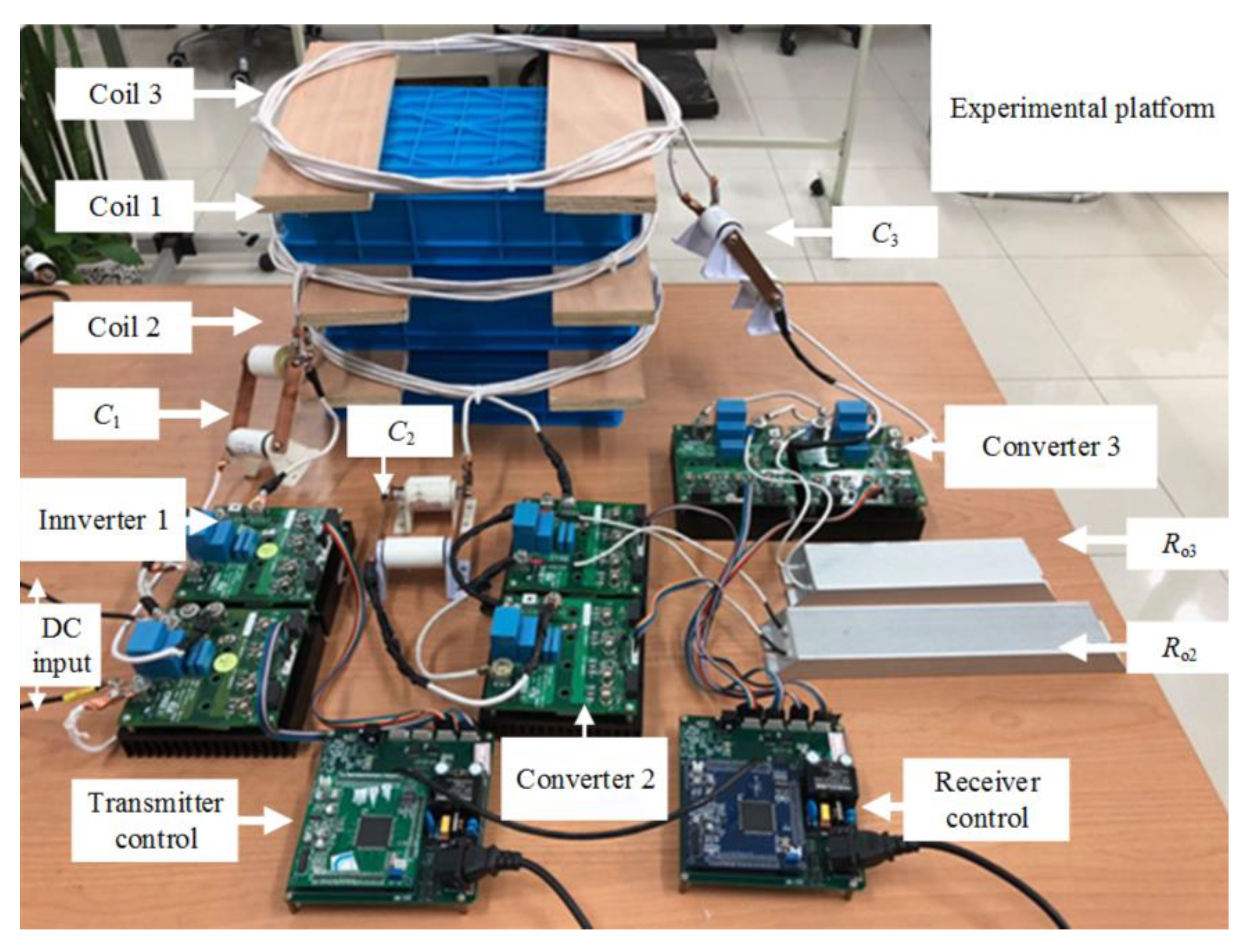
Figure 7 shows the implemented experimental prototype of the proposed system. The primary bridge inverts the DC voltage into 100-kHz AC voltage. Coil 1 transmits power to the two receiver coils: coils 2 and 3. The receiver coils are positioned to reduce magnetic coupling between them. The controllers of the transmitter coil and receiver coils communicate through a synchronization signal between the two controller boards.
5.1. Result of Impedance Matching Control
To verify the effectiveness of the impedance matching control method, the system parameters are shown in Table 1, Ro2 is 8 Ω, Ro3 is 8 Ω and Uin is 20 V. Q1 leads Q4 by 45°, that is β1 = 45°. Change the β2 and β3 to verify the optimal efficiency of MRWPT system.
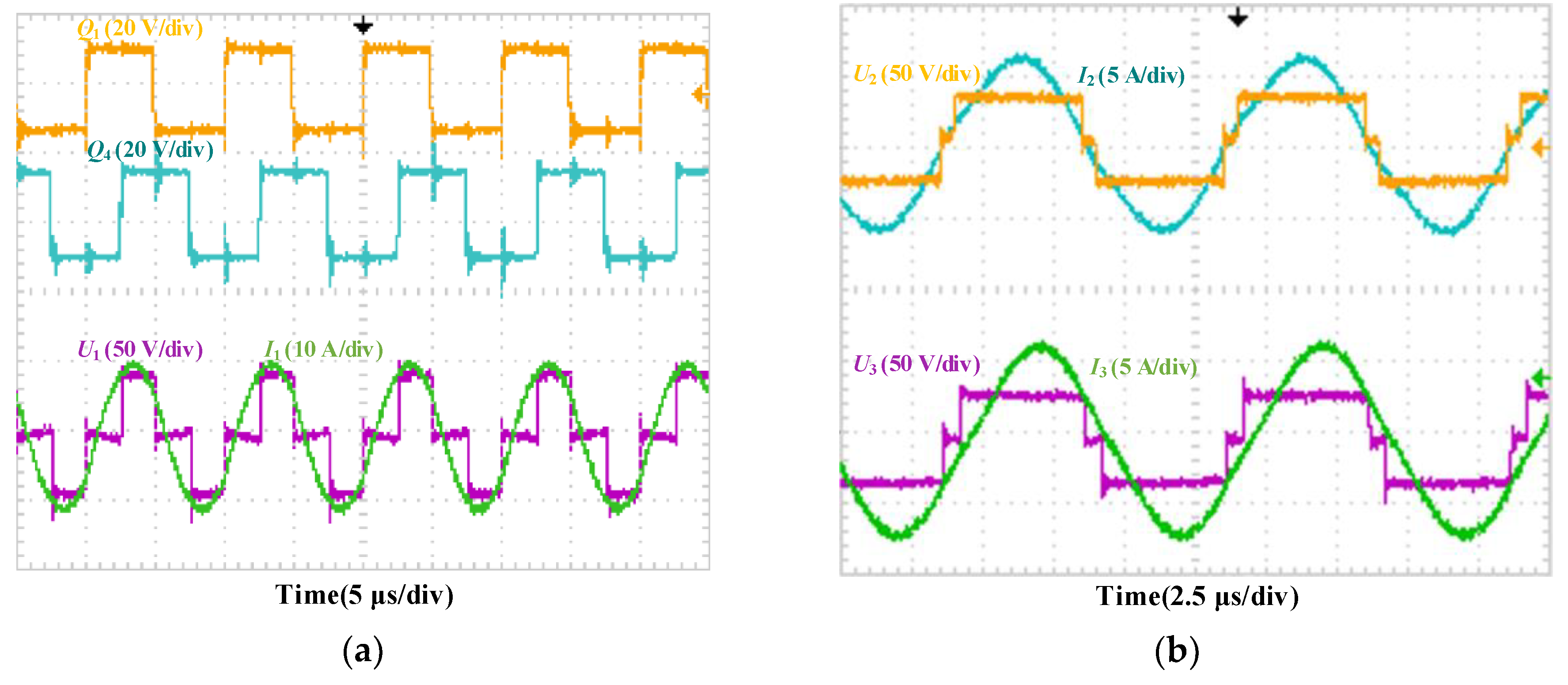
Figure 8 shows the experimental waveforms, where transmitter waveforms are shown in Figure 8a, and receiver waveforms are shown in Figure 8b. The converter voltage U1 of the transmitter is controlled by Uin and shift phase of driver signal Q1–Q4 (Figure 8). To simplify controlling the U1, the Q1 leads Q4 by 45°, and system changes the Uin to control the U1. To assure system operates at the resonant condition, Ui and Ii were in phase in principle (Figure 8). However, I1 had a slightly capacitive phase due to the parasitic parameter and impedance error of the circuit, but the requirement of the system was still satisfied (Figure 8a).
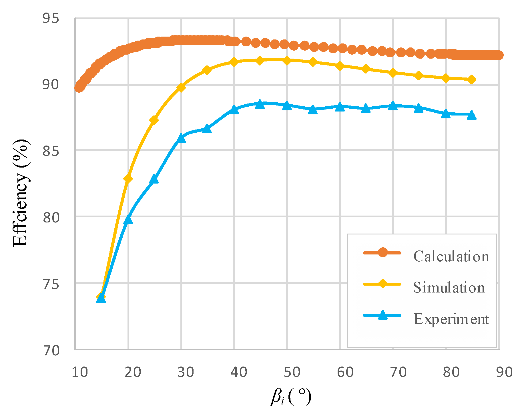
Experiments discussed the best impedance matching technology based on(7). The two-receiver WPT system operates under the resistance matching condition, according to (7). Under this condition, the system’s efficiency is not relevant to the parameters U1, L1 and C1, but the output power changes with Uin increasing. Figure 9 presents the derived efficiency of the two-receiver WPT system in this study; Uin remained unchanged, but the equivalent resistance Reqi increased. During initialization, to simplify the system, the load resistances Ro2 and Ro3 were both set to 8 Ω for the two receiver coils (Table 1). Based on(15), the system adopted controlling β2 and β3 to control the equivalent resistances Reqi. The efficiency vs. β2 and β3 is shown in Figure 9 to verify the trend of efficiency vs. equivalent resistances. The optimal equivalent resistances of receivers (from(7)) were similar due to the similar parameters of the receivers, and hence experiment set β2 = β3 at each time to simplify the experiment.
Gradually increasing β2 and β3 to increase the equivalent resistances yielded the efficiency trends presented in Figure 9. As illustrated in this figure, the experimental and simulation results were essentially correlated with the mathematical model, and the system achieved maximum efficiency when it operated at the best equivalent resistance derived by(7). The trends of simulated and experimental results agreed with the calculated results in Figure 9, and the optimal β2 and β3 of simulated and experimental results are higher due to lower power transfer efficiency. However, although the system achieved maximum efficiency, the output power levels were uncontrollable. Additional control strategies should be proposed to control the output power of the two-receiver WPT system.
5.2. Result of Target Power Control
This section discusses the effectiveness of TPC method of providing target power, and add comparison with the impedance matching method. The proposed TPC method based on a simplified model has the advantage of controlling the output power.
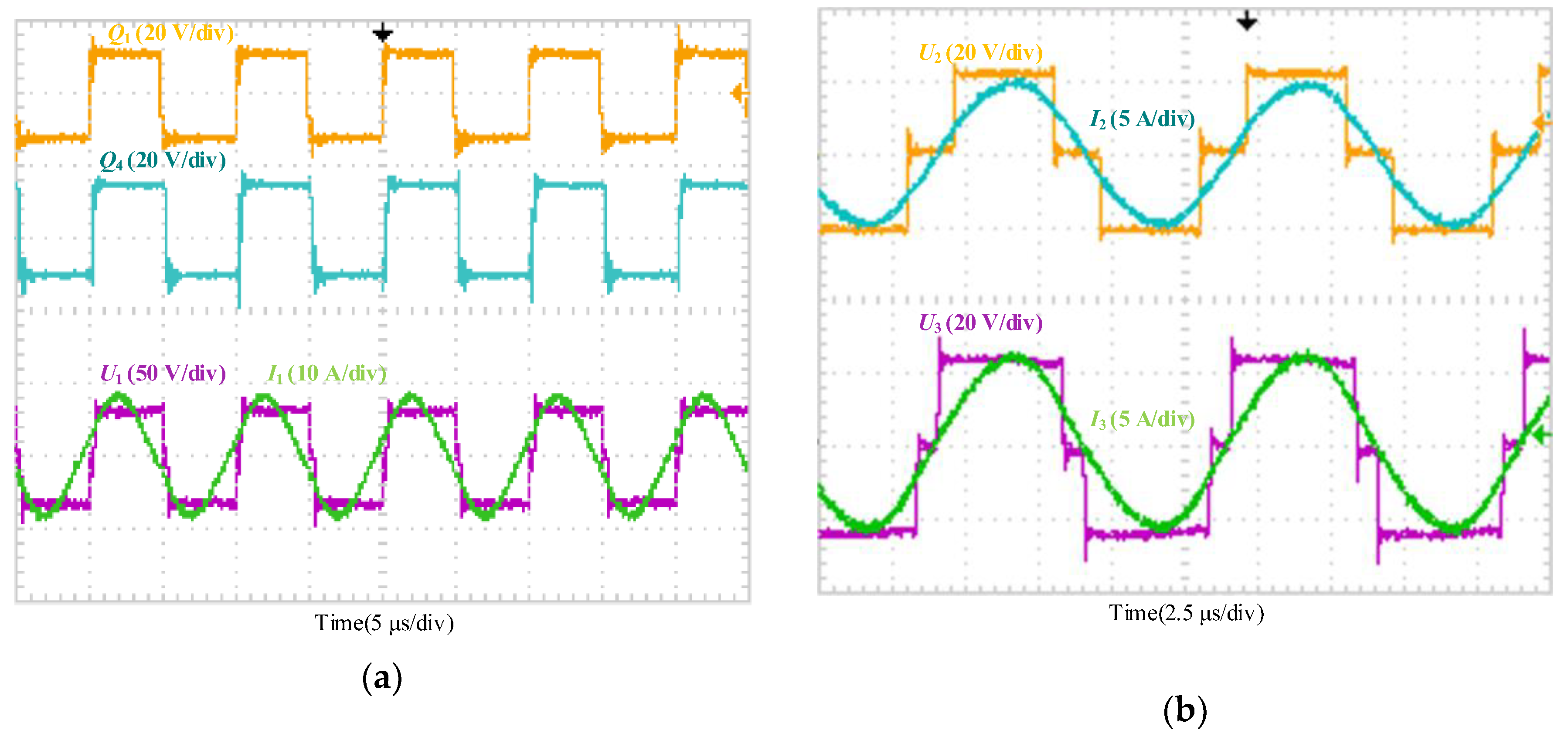
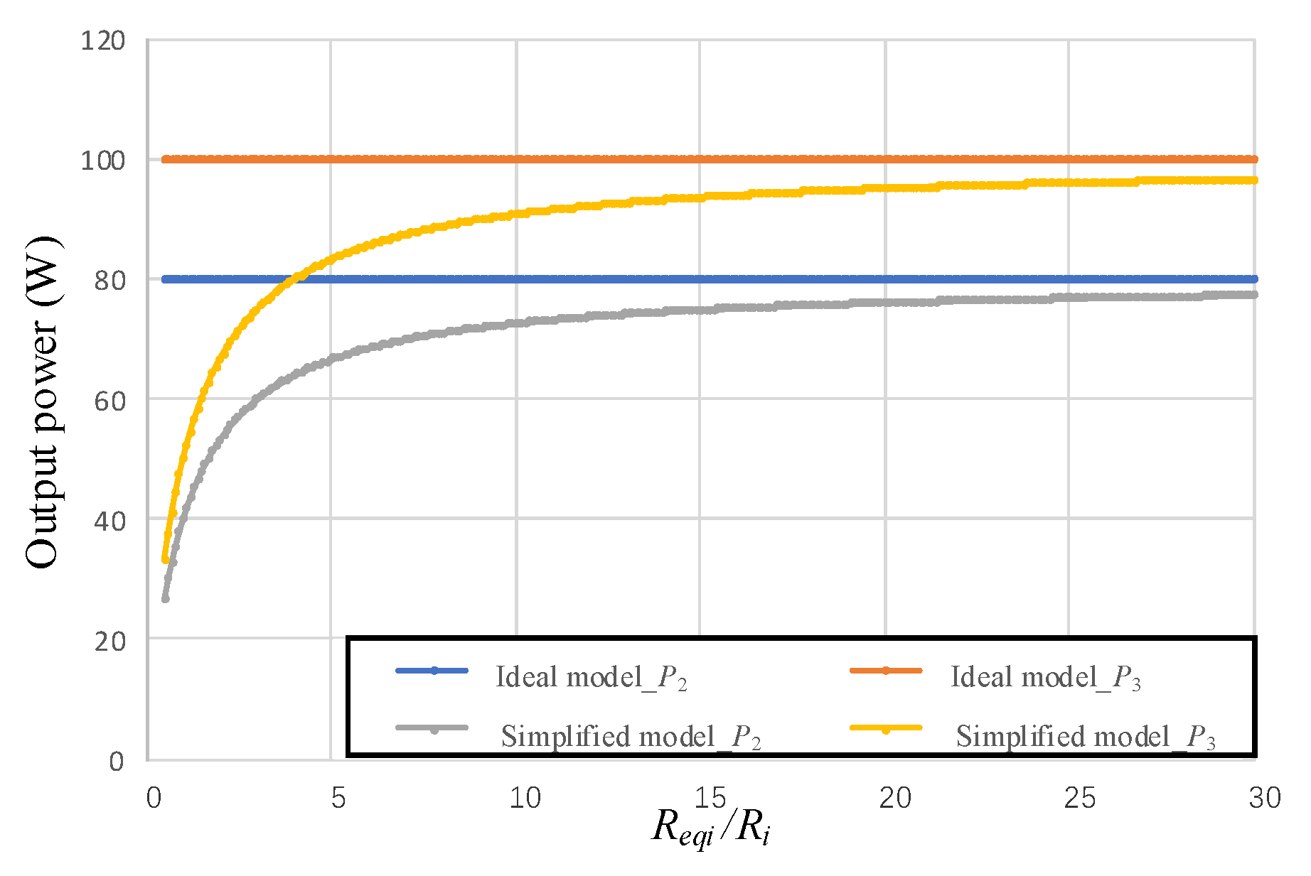
During initialization, the parameters of proposed target power method followed Table 1, but the Ro2 and Ro3 was set 8 Ω, 5 Ω respectively. Uin was set 33 V and β1 was set 85°. The experimental waveforms are shown in Figure 10. First, we compare the simplified model with ideal model under different Reqi by calculation. The calculation results from MATLAB obtained using the simplified model (14) are compared with those obtained using an ideal model(11), as shown in Figure 11, to illustrate the effectiveness of simplified model. Calculations were based on the parameters given by Table 1, and the target powers set P2 = 100 W, P3 = 80 W. The output power obtained by using the simplified model varied at different Reqi values are compared with target powers (Figure 11). Specifically, when Reqi increased, the powers and efficiencies obtained using the simplified model are getting close to the power and efficiency obtained using ideal model. From Figure 11, when the equivalent resistances are over 10 times bigger than the coils resistances, the output powers of simplified model approach the powers of ideal model. In most practical applications, the resistance of coils are relatively small compared with the equivalent load resistance; hence, the simplified model can approximately replace the ideal model.
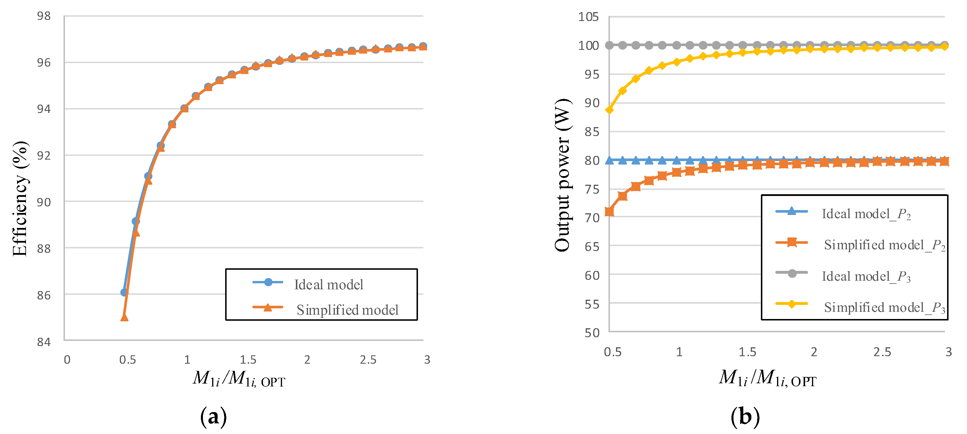
Second, this study further compares the efficiency and output power obtained by using the simplified model (14) with those obtained using the ideal model (11) at different mutual inductance ratios (M1i/M1iopt) by calculation. For simplicity, the mutual inductances M12 and M13 increase with the same ratio M1i/M1i, OPT (i = 2, 3), where M1iopt are obtained by(12). Calculations including calculation of M1iopt are based on the parameters given by Table 1, and the target powers are set P2 = 100 W, P3 = 80 W. The calculated optimal mutual inductances (12) are derived as M12, OPT = 3.15 µH, M13, OPT = 3.35 µH. However, from Figure 2, efficiency increases rapidly when the mutual inductances increased, and hence it is better to set the mutual inductances as large as possible instead of setting the mutual inductances equal the optimal mutual inductances M1i, OPT. Figure 12 demonstrates the differences between the ideal model and the simplified model at different mutual inductance. The efficiency and output power obtained using the two models varied at different mutual inductance levels. In simplified model, the equivalent resistance is set to the optimal equivalent resistance Reqi [From (19)] according to different M12 and M13 values in order to achieve the target output power. Besides, because the analytic solution of Reqi at ideal model cannot be derived through(4), (8), the efficiency and output power of ideal model at Figure 12 are calculated by numerical solutions of Reqi through (4), (8). The numerical solutions are derived by substituting each M1i value into the (4) (10) to achieve the Reqi value correspondingly. As the mutual inductance increased, the efficiency and output power obtained using the simplified model approximated those obtained using the ideal model. When the mutual inductances M1i are twice bigger than the optimal mutual inductance M1i, OPT, the errors are extremely small.
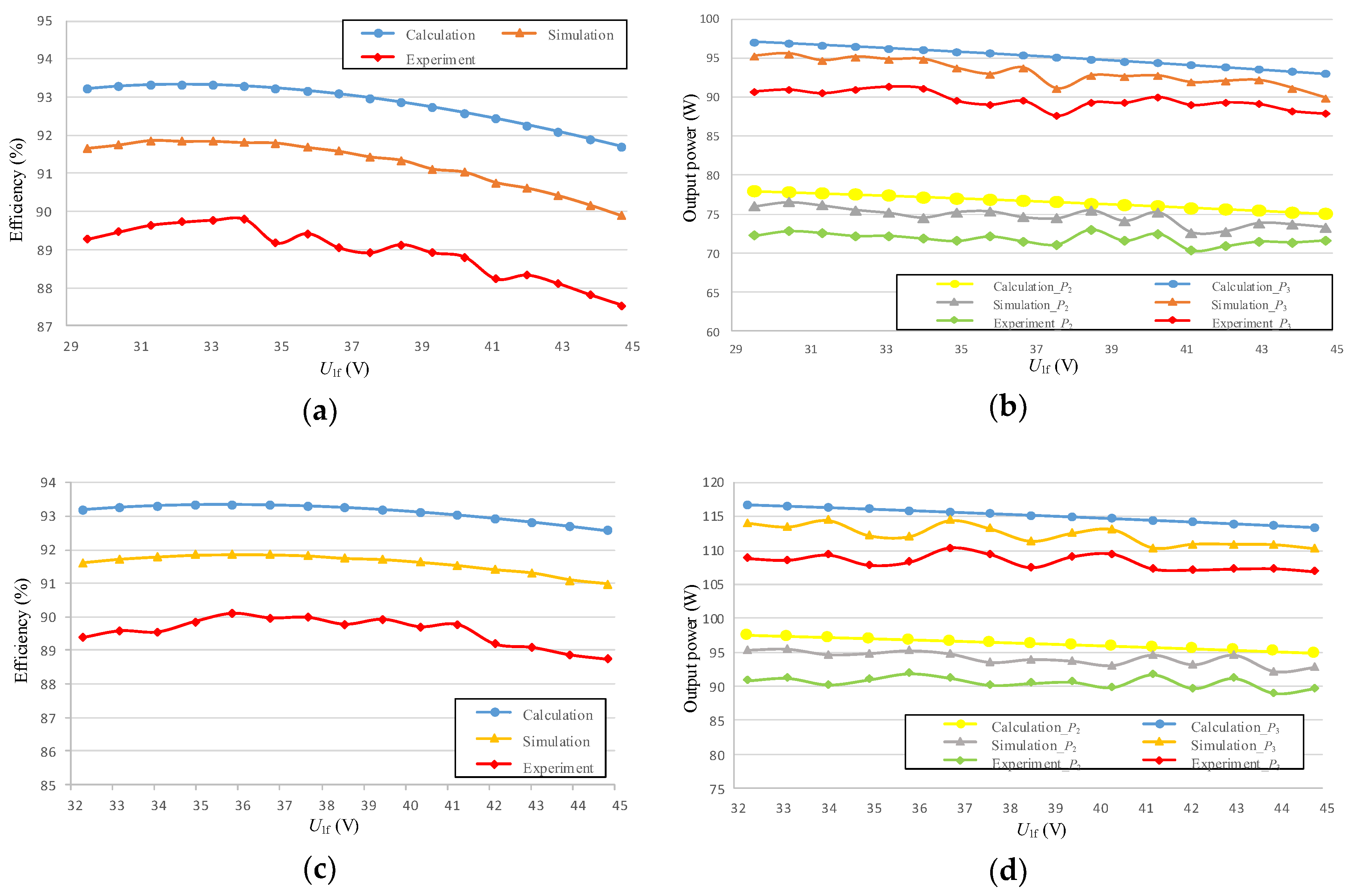
Third, to verify the proposed TPC method, Ro2 and Ro3 are set 8 Ω and 5 Ω respectively and the parameters are given in Table 1. Regarding the initialization of the system parameters in the experiment, Uin is set to 5 V and β1 is set to 85°; moreover, the system is tuned to operate under the resonant condition, that is, jωLi + 1/jωCi = 0 (i = 1, 2, 3). The tuning of U1f is according to Figure 13. After the initialization process in Section 4.1, the input voltage Uin is gradually increased and the equivalent resistances are manipulated accordingly to track the efficiency and output power variation trends. U1f is calculated by (1) and the experiment results versus U1f are drawn as Figure 13a,b. As illustrated in Figure 13a, the observed efficiency levels vary among the mathematical model, simulation model, and experiments; however, for each model, the efficiency levels exhibit relatively similar trends at the various target power levels. The system achieves maximum efficiency when U1f is 35.9, 35.9 and 34.1 V respectively, and the efficiency levels of the mathematical model, simulation model, experimental prototype are 93.3%, 91.85%, and 89.8%, respectively. As presented in Figure 13b, the target output power levels are set 80 and 100 W, and the output power levels of the simulation model and experimental prototype are essentially correlated with those of the mathematical model. Specifically, the P2 levels of the mathematical model, simulation model, and experimental prototype are 77.51, 76.13, and 71.89 W, respectively; moreover, the P3 levels of the mathematical model, simulation model, and experimental prototype are 96.48, 94.69, and 91.14 W, respectively. According to Figure 13b, the system incurs an extra loss, and the power levels of the simulation model and experimental prototype are lower than those of the mathematical model. Additional comparisons are provided in Figure 13c, d. The system achieves maximum efficiency when U1 was 35.8 V, and the efficiency levels of the mathematical model, simulation model, experimental prototype are 93.29%, 91.82%, and 89.9%, respectively. From the simulation and experiment results, the TPC is valid for MRWPT system.
Finally, this study also compares the proposed TPC method with the impedance matching method. In the application of the impedance matching method, the system is operated using the parameters presented in Table 1, and Req2 and Req3 satisfies the impedance matching condition outlined in (7). Table 2 presents the comparison result. The efficiency using impedance matching method are obtained under the same circuit parameters as the system using TPC method. From Table 2, the maximum efficiency of the proposed TPC method is very close to the efficiency of the impedance matching method. Besides, the proposed TPC method has the advantage of controlling the output power, whereas it’s difficult for impedance matching method to control the power. Thus, sacrificing a slight efficiency loss for obtaining target output power is worthwhile. Furthermore, this study compares the output power of the proposed two-receiver WPT system obtained using a simplified-model-based control strategy (14) with the output power obtained using an ideal model (11). According to Figure 11, the proposed control strategy can provide the target power with a small voltage drop; this can satisfy the output power requirements of systems with two receiver coils. For practical applications such as those requiring a 1-kW output power, the proposed control system is suitable for achieving the target power with high efficiency. However, the system still results in voltage drops due to the simplification of (11) and extra power loss. This problem can be solved by improving the input voltage and including an additional control device in the MOSFET of the receiver coils; however, the inclusion of an additional control device would increase system complexity, which is not economical to realize a MRWPT system.
6. Conclusions
This study develops a two-receiver WPT system and a TPC method that can enable the system to achieve efficient target output power levels. Recent research has focused on achieving maximum efficiency by using impedance matching technology; however, the output power of such systems seldom satisfies the target output power requirement. Moreover, mutual inductance plays a more important role in improving system efficiency than matching resistance does; thus, systems should prioritize attaining high mutual inductance levels. In two-receiver coil systems, manipulating the phase of receiver coils by using active-bridge control is difficult. To address these limitations, this study establishes a simplified phase control model that entails compensating the phase during system parameter initialization. In MRWPT systems, solving (2) and (11) to derive the analytic solution of Reqi is difficult tasks. This study solves this problem by simplifying the mathematical model and deriving an approximate analytic solution of Reqi in the form of Pi. Consequently, the two-receiver WPT system has a simulated efficiency of 91.3% and an experimental efficiency of 90.1% at a frequency of 100 kHz, as well as achieving target power levels of 80 and 100 W.
Author Contributions
Conceptualization, W.C.; Methodology, W.C.; Software, W.C.; Validation, W.C.; Formal Analysis, W.C.; Investigation, W.C.; X.L. and L.S.; Resources, W.C.; Data Curation, W.C.; Writing-Original Draft Preparation, W.C.; Writing-Review & Editing, W.C.; D.M.; H.T. and X.L.; Visualization, W.C.; Supervision, D.M.; H.T.; and X.L.; Project Administration, H.T.
Funding
This research received no external funding
Conflicts of Interest
The authors declare no conflict of interest.
References
- Si, P.; Hu, A.P.; Malpas, S.; Budgett, D. A frequency control method for regulating wireless power to implantable devices. IEEE Trans. Biomed. Circuits Syst. 2008, 2, 22–29. [Google Scholar] [CrossRef] [PubMed]
- Xue, R.F.; Cheng, K.W.; Je, M. High-Efficiency Wireless Power Transfer for Biomedical Implants by Optimal Resonant Load Transformation. IEEE Trans. Biomed. Circuits Syst. I Regul. Pap. 2013, 60, 867–874. [Google Scholar] [CrossRef]
- Meng, M.; Kiani, M. A Hybrid Inductive-Ultrasonic Link for Wireless Power Transmission to Millimeter-Sized Biomedical Implants. IEEE Trans. Biomed. Circuits Syst. II Express Briefs 2016, 64. [Google Scholar] [CrossRef]
- Ramrakhyani, A.K.; Mirabbasi, S.; Mu, C. Design and optimization of resonance-based efficient wireless power delivery systems for biomedical implants. IEEE Trans. Biomed. Circuits Syst. 2011, 5, 48–63. [Google Scholar] [CrossRef] [PubMed]
- Kuipers, J.; Bruning, H.; Bakker, S.; Rijnaarts, H. Near field resonant inductive coupling to power electronic devices dispersed in water. Sens. Actuators A Phys. 2012, 178, 217–222. [Google Scholar] [CrossRef]
- Niu, W.; Gu, W.; Chu, J.; Shen, A. Frequency splitting of underwater wireless power transfer. In Proceedings of the IEEE International Workshop on Electromagnetics: Applications and Student Innovation Competition, Nanjing, China, 16–18 May 2016. [Google Scholar]
- Klontz, K.W.; Divan, D.M.; Novotny, D.W.; Lorenz, R.D. Contactless power delivery system for mining applications. IEEE Trans. Ind. Appl. 1995, 31, 27–35. [Google Scholar] [CrossRef]
- Zhao, D.; Ding, E.J.; Xue, H. Multiple-Input Single-Output Wireless Power Transmission System for Coal Mine Application. Appl. Mech. Mater. 2014, 462–463, 900–904. [Google Scholar] [CrossRef]
- Tampubolon, M.; Pamungkas, L.; Chiu, H.J.; Liu, Y.C.; Hsieh, Y.C. Dynamic Wireless Power Transfer for Logistic Robots. Energies 2018, 11, 527. [Google Scholar] [CrossRef]
- Imura, T.; Hori, Y. Optimization using transmitting circuit of multiple receiving antennas for wireless power transfer via magnetic resonance coupling. In Proceedings of the 2011 IEEE 33rd International Telecommunications Energy Conference (INTELEC), Amsterdam, The Netherlands, 12 December 2011. [Google Scholar] [CrossRef]
- Fu, M.; Zhang, T.; Ma, C.; Zhu, X. Efficiency and Optimal Loads Analysis for Multiple-Receiver Wireless Power Transfer Systems. IEEE Trans. Microw. Theory Tech. 2015, 63, 801–812. [Google Scholar] [CrossRef]
- Fu, M.; Yin, H.; Zhu, X.; Ma, C. Analysis and Tracking of Optimal Load in Wireless Power Transfer Systems. IEEE Trans Power Electron. 2015, 30, 3952–3963. [Google Scholar] [CrossRef]
- Berger, A.; Agostinelli, M.; Vesti, S.; Oliver, J.A.; Cobos, J.A.; Huemer, M. A Wireless Charging System Applying Phase-Shift and Amplitude Control to Maximize Efficiency and Extractable Power. IEEE Trans Power Electron. 2015, 30, 6338–6348. [Google Scholar] [CrossRef]
- Li, H.; Li, J.; Wang, K.; Chen, W. A Maximum Efficiency Point Tracking Control Scheme for Wireless Power Transfer Systems Using Magnetic Resonant Coupling. IEEE Trans Power Electron. 2015, 30, 3998–4008. [Google Scholar] [CrossRef]
- Zhang, T.; Fu, M.; Ma, C.; Zhu, X. Optimal load analysis for a two-receiver wireless power transfer system. In Proceedings of the Wireless Power Transfer Conference, Jeju, South Korea, 8–9 May 2014; pp. 84–87. [Google Scholar]
- Li, Y.; Mai, R.; Liu, Y.; He, Z. Efficiency optimising strategy for dual-coupled transmitters based WPT systems. Electron. Lett. 2016, 52, 1877–1879. [Google Scholar] [CrossRef]
- Liu, X.; Wang, T.; Yang, X.; Jin, N.; Tang, H. Analysis and Design of a Wireless Power Transfer System with Dual Active Bridges. Energies 2017, 10, 1588. [Google Scholar] [CrossRef]
- Fu, M.; Yin, H.; Liu, M.; Wang, Y.; Ma, C. A 6.78 MHz Multiple-Receiver Wireless Power Transfer System with Constant Output Voltage and Optimum Efficiency. IEEE Trans Power Electron. 2017, 33, 33. [Google Scholar] [CrossRef]
- Lee, K.; Cho, D.H. Analysis of Wireless Power Transfer for Adjustable Power Distribution among Multiple Receivers. IEEE Antennas Wirel. Propag. Lett. 2015, 14, 950–953. [Google Scholar] [CrossRef]
- Fu, M.; Yin, H.; Ma, C. Megahertz Multiple-Receiver Wireless Power Transfer Systems with Power Flow Management and Maximum Efficiency Point Tracking. IEEE Trans. Microw. Theory Tech. 2017, 65. [Google Scholar] [CrossRef]
- Fu, M.; Zhang, T.; Zhu, X.; Luk, C.K.; Ma, C. Compensation of Cross Coupling in Multiple-Receiver Wireless Power Transfer Systems. IEEE Trans. Ind. Inf. 2016, 12, 474–482. [Google Scholar] [CrossRef]
Figure 1.
Schematic and equivalent circuits of two-receiver WPT system: (a) schematic circuit of two-receiver WPT system; (b) equivalent circuit of two-receiver WPT system.
Figure 1.
Schematic and equivalent circuits of two-receiver WPT system: (a) schematic circuit of two-receiver WPT system; (b) equivalent circuit of two-receiver WPT system.
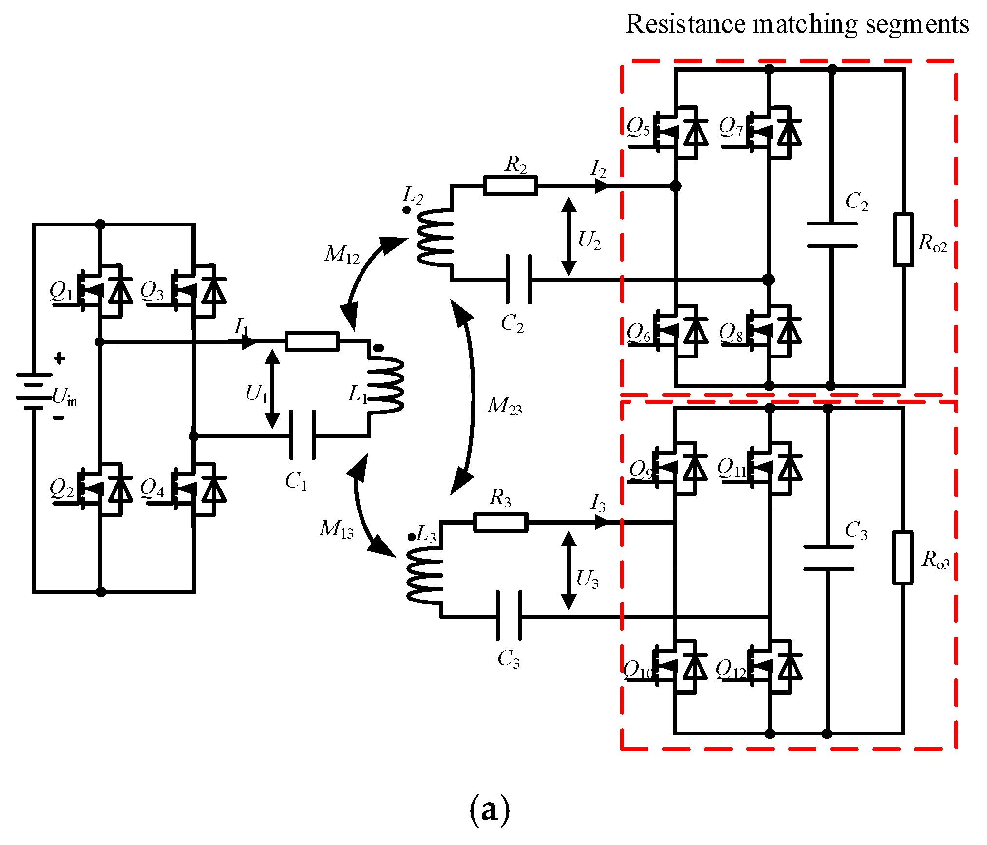
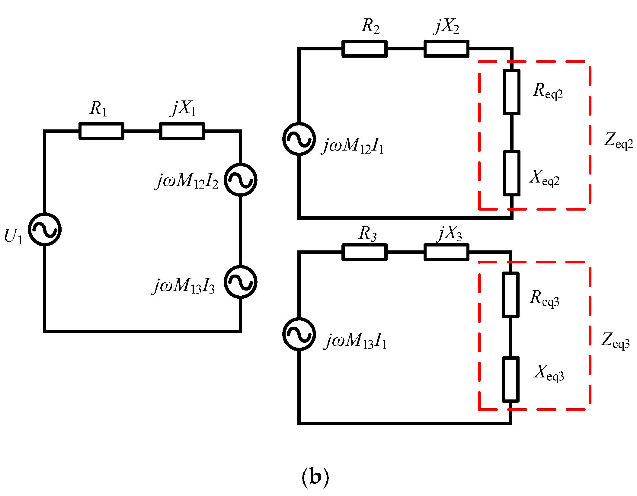
Figure 2.
Power transfer efficiency versus mutual inductance levels under the best matching condition.
Figure 2.
Power transfer efficiency versus mutual inductance levels under the best matching condition.
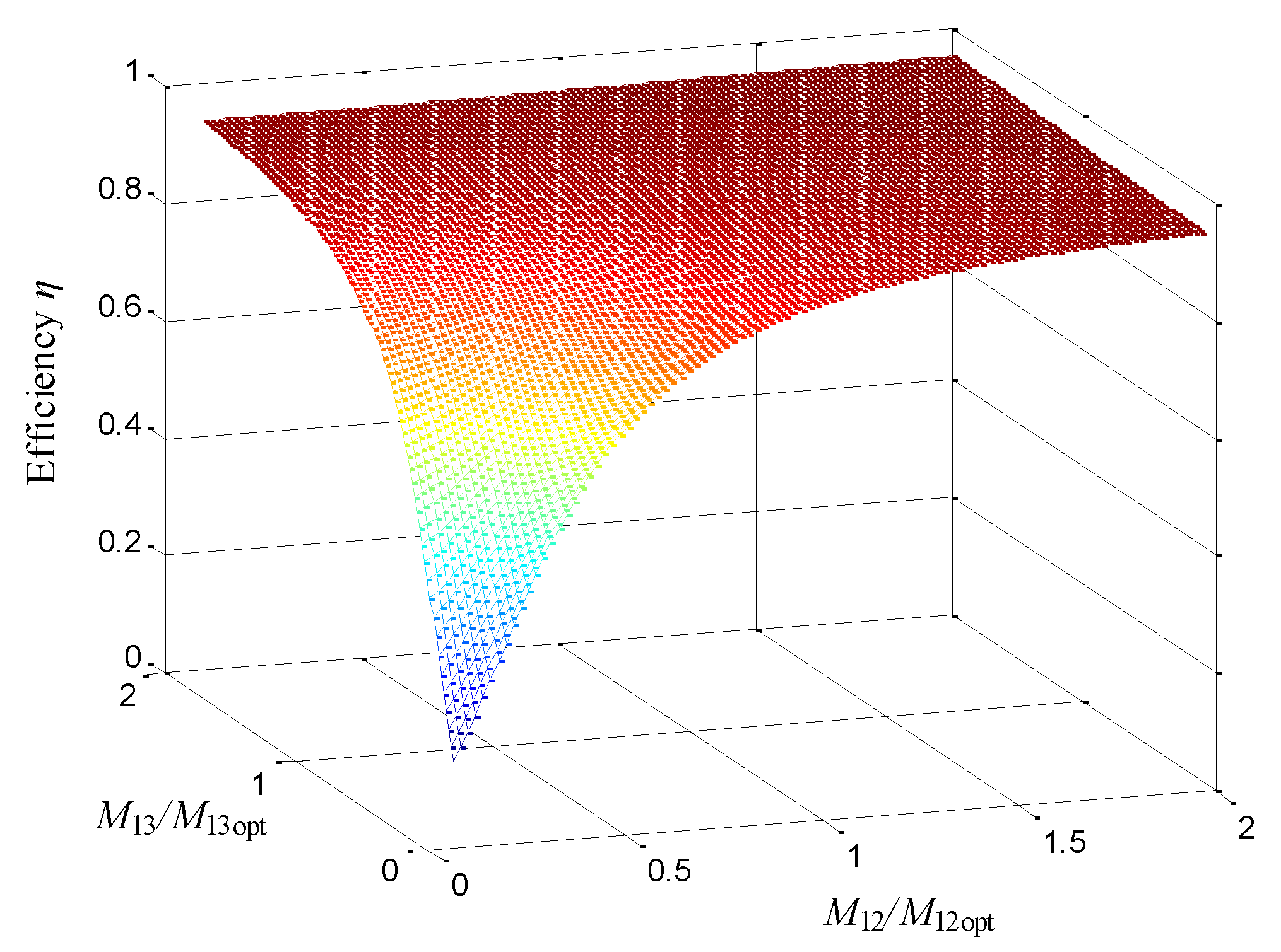
Figure 3.
Efficiency versus resistance ratio at fixed mutual inductance: (a) efficiency versus Reqi/Reqi, OPT; (b) contour map of efficiency.
Figure 3.
Efficiency versus resistance ratio at fixed mutual inductance: (a) efficiency versus Reqi/Reqi, OPT; (b) contour map of efficiency.

Figure 4.
Drive signals, square-wave voltages and resonant currents waveforms in SS WPT system: (a) transmitter active bridge; (b) receiver active bridge.
Figure 4.
Drive signals, square-wave voltages and resonant currents waveforms in SS WPT system: (a) transmitter active bridge; (b) receiver active bridge.

Figure 5.
Flowchart of system control program.
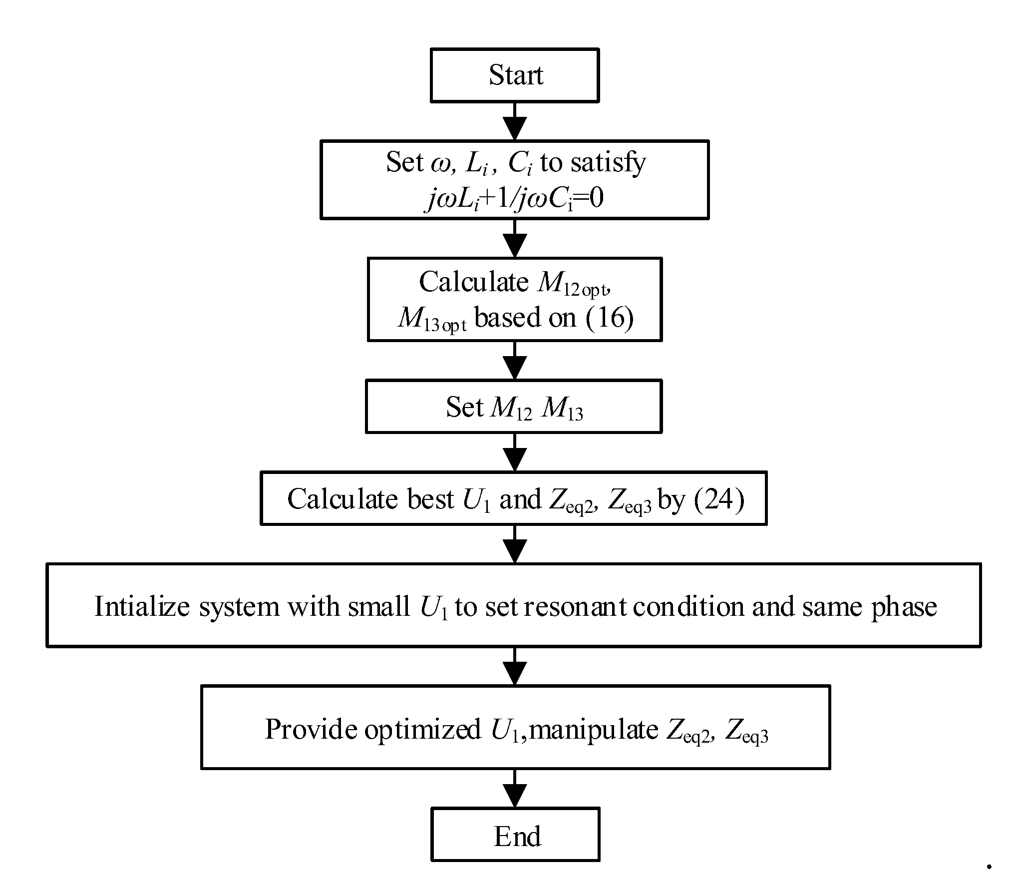
Figure 6.
Two-receiver WPT system configuration.

Figure 7.
Experimental platform.

Figure 8.
Experimental waveform: (a) transmitter coil; (b) receiver coils.

Figure 9.
Efficiency trends obtained for mathematical model, simulation model, and experimental prototype.
Figure 9.
Efficiency trends obtained for mathematical model, simulation model, and experimental prototype.

Figure 10.
Experimental waveform: (a) transmitter coil; (b) receiver coils.

Figure 11.
Power of simplified model and ideal model versus resistance ratio (Reqi/Ri).

Figure 12.
Efficiency of simplified model and ideal model versus mutual inductance ratio (M1i/M1i, OPT): (a) efficiency results; (b) power results.
Figure 12.
Efficiency of simplified model and ideal model versus mutual inductance ratio (M1i/M1i, OPT): (a) efficiency results; (b) power results.

Figure 13.
Result comparison: (a) efficiency levels of mathematical model, simulation model, and experimental prototype for target power levels of 80 and 100 W; (b) output power levels of the mathematical model, simulation model, and experimental prototype for target power levels of 80 and 100 W; (c) efficiency levels of the mathematical model, simulation model, and experimental prototype for target power levels of 100 and 120 W; (d) output power levels of the mathematical model, simulation model, and experimental prototype for target power levels of 100 and 120 W.


Table 1.
Key parameters of proposed system.
| Symbol | Quantity | Value |
|---|---|---|
| L1, L2, L3 C1, C2, C3 R1, R2, R3 f M12, M13 d φ1, φ2, φ3 | inductances of coils compensation capacitor parasitic resistances operating frequency mutual inductance distance between adjacent coils phase (see in Figure 4) | 22.78 µH, 22.97 µH, 22.97 µH 114 nF, 110 nF, 110 nF 0.01925 Ω, 0.01279 Ω, 0.01158 Ω 100 kHz 5 µH, 5 µH 12 cm 0, 0, 0 |
Table 2.
Efficiency levels of different models for target power levels of 80 and 100 W.
| Method | Math Model | Simulation | Experiment |
|---|---|---|---|
| Impedance matching method Target power control method | 93.4% 93.3% | 91.87% 91.85% | 90.1% 89.8% |
© 2018 by the authors. Licensee MDPI, Basel, Switzerland. This article is an open access article distributed under the terms and conditions of the Creative Commons Attribution (CC BY) license (http://creativecommons.org/licenses/by/4.0/).
Share and Cite
MDPI and ACS Style
Cai, W.; Ma, D.; Tang, H.; Lai, X.; Liu, X.; Sun, L. Highly Efficient Target Power Control for Two-Receiver Wireless Power Transfer Systems. Energies 2018, 11, 2726. https://doi.org/10.3390/en11102726
AMA Style
Cai W, Ma D, Tang H, Lai X, Liu X, Sun L. Highly Efficient Target Power Control for Two-Receiver Wireless Power Transfer Systems. Energies. 2018; 11(10):2726. https://doi.org/10.3390/en11102726
Chicago/Turabian StyleCai, Weikun, Dianguang Ma, Houjun Tang, Xiaoyang Lai, Xin Liu, and Longzhao Sun. 2018. "Highly Efficient Target Power Control for Two-Receiver Wireless Power Transfer Systems" Energies 11, no. 10: 2726. https://doi.org/10.3390/en11102726
Note that from the first issue of 2016, this journal uses article numbers instead of page numbers. See further details here.