Consensus Control of Distributed Energy Resources in a Multi-Bus Microgrid for Reactive Power Sharing and Voltage Control


1
China Southern Power Grid EPRI, 11 Kexiang Rd, Guangzhou 510663, China
2
eMIT, LLC., 125 N Lake Ave., Pasadena, CA 91101, USA
*
Author to whom correspondence should be addressed.
Energies 2018, 11(10), 2710; https://doi.org/10.3390/en11102710
Submission received: 1 August 2018
/
Revised: 20 September 2018
/
Accepted: 26 September 2018
/
Published: 11 October 2018
(This article belongs to the Section F: Electrical Engineering)
Abstract
:The hierarchical control architecture, including layers of primary, secondary and tertiary controls, is becoming the standard operating paradigm for microgrids (MGs). Two major factors that limit the adoption of existing hierarchical control in microgrid are the low accuracy in reactive power sharing and the requirement for complex communication infrastructure. This paper addresses this problem by proposing a novel distributed primary and secondary control for distributed generators dispersed in a multi-bus microgrid. The proposed method realizes voltage control and accurate reactive power sharing in a distributed manner using minimum communication. Each distributed generator only needs its own information and minimum information from its neighboring units. Topology of the network can be flexible which supports the plug-and-play feature of microgrids. In a distribution system, high R/X ratio and system imbalance can no longer be neglected and thus the sequence component analysis and virtual impedance are implemented in the proposed control framework. The proposed framework is validated by simulation results on a MG testbed modified from the IEEE 13-bus distribution system.
1. Introduction
In recent years, the impact of microgrid has been increasing. It acts as a solution to large-scale penetration of renewable energy, including wind, photovoltaic (PV) etc. By 2017, the market for microgrid in the whole world had achieved more than 8 billion US dollars. Moreover, the microgrid market continues to rapidly grow with the growth of renewable energy [1]. However, due to the intermittent nature of renewable energy resources, proper scheduling and control of generation units in MG is often difficult. Equipping the renewables in microgrids with additional storage devices is regarded as a promising solution. Usually, such a hybrid system is called distributed generation (DG) [2,3].
In microgrids, there are two typical control strategies: the V-f control and the P-Q control. In most cases, the V-f control represents grid-forming control and the P-Q control represents grid-following control [4]. The P-Q control is used when voltage and frequency references are provided by either master DG(s) in the islanded mode or the main grid in grid-tied mode to regulate the active and reactive power outputs of a DG based on the given references. On the contrary, the V-f control is an explicit grid-forming control mostly used in islanded microgrids. DGs use V-f control to regulate the frequency and voltage of a microgrid with active and reactive power injection. The control reference of DG units needs to be adjusted when multiple DG units share loads and the loads change. Considering these factors, the centralized hierarchical control framework building with primary control and secondary control is widely used [5,6,7].
Droop control is a straightforward yet effective automatic generation control (AGC) method for load sharing in power transmission system. Therefore, researchers take the concept of droop control to MG for power sharing among DGs when load varies to maintain the MG power balance. Typically, reactive power is shared within DGs in a microgrid based on the maximum capacity of each DG. However, it is not trivial but difficult to achieve the reactive power sharing objective among DGs. The difficulty mainly comes from the fact that droop control of each DG could be quite distinctive because of various output filters and the network impedance [8]. In fact, the droop control itself was first proposed to solve the single bus AGC problem. When it comes to a multi-bus system, the traditional droop control bears several limitations, such as the inaccuracy in reactive power sharing. It is noted from the literature that the voltage droop control is most effective for the cases when multiple DGs connecting to one single bus to supply a single load [9,10,11]. It is necessary to extend the droop control in microgrids to accurately share reactive power among DGs.
For the sake of eliminating the frequency and voltage deviation resulted from droop control, a centralized secondary control is proposed in [12]. In the centralized secondary control proposed in [12], the central controller is required to interact with all DGs in the microgrid. This centralized control system strongly relies on timely inputs from DGs therefore requires high-bandwidth and low latency data communication infrastructure. Considering the number of distributed generators that may exist in a microgrid, adopting the centralized communication and control structure will require a huge amount of communication channels, which is obviously cost prohibitive. Moreover, the entire secondary control will defunct in the case the central controller fails, as an inherent limitation of the centralized control structure.
Recent studies implemented the MG controller with enhanced distributed or decentralized control strategies requiring only uncritical communication, although the controller may not be running on the optimal condition. The consensus control theory has been studied and applied in different fields [13,14]. According to consensus control, all agents in a network will achieve an agreement to approach the predefined states of the entire system. Especially, the first P-f droop controller using consensus control is introduced in [15], while the first secondary controller using consensus control is introduced and demonstrated on a four-bus system in [16,17]. However, the reactive power sharing issue remains unresolved due to the assumption of lossless network model used in the above two controllers. Besides, the above two controllers require that the voltages in all DG output terminals be uniform, which caused the secondary voltage controller to be off the target. Actually, this is a common issue in most existing works in the area of MG control. He et al. [18] claimed that the reactive power sharing issue could be resolved with considering only purely inductive transmission line. Bidram et al. [19] introduced an approach with consensus control to solve the power sharing problem for microgrid in islanded mode. However, large mismatches were observed in reactive power sharing in the above two methods [18,19] when R/X ratio of distribution network is high. Lu et al. [20] and [21] proposed a controller based on consensus control when loss is considered in microgrid network. However, another issue of voltage convergence came up. In addition, system unbalance is neglected in the distribution system, which is far from the reality [22].
This paper proposes a distributed cooperative control framework based on the control idea modified from the conventional primary and secondary controls. The idea of consensus control loop, virtual impedance and sequence component analysis are combined to solve the reactive power issue for a general distribution network with high R/X ratio and considerable imbalance among three phases. The following contributions are made.
Firstly, the root cause of the reactive power sharing problem is identified and the communication between all DGs is proved to be necessary for solving the reactive power sharing and voltage regulation problem. Secondly, a two-level control structure is proposed as the consensus based primary and secondary control, with minimum communication among DGs. The proposed method is not only flexible and adaptive to system topology changes, but also making plug-and-play possible in MGs. Thirdly, to make this work as a complete solution for a real practical application, a stationary αβ transformation based sequence component analysis of an unbalanced three-phase system is employed. A voltage compensation model is applied [23] to autonomously compensate for the voltage unbalance. Finally, the virtual impedance loop is proposed to solve the large R/X ratio problem prior to the consensus based droop control. This paper demonstrates that control with a proper virtual impedance loop can be a potential solution for the reactive power sharing problem in a general distributed network.
2. Hierarchical Control
Figure 1 shows an inverter with the standard dynamic control model. This model consists of a current controller in inner loop, a voltage controller in outer loop, an active power and reactive power droop controller in outer loop and a secondary controller for system-level control. Since the two inner loop controllers come with very fast response time and do not impact the primary droop and secondary control loops, the two inner loop controllers are not considered in this work. To simplify the analysis, the distributed generation resources with power electronic interfaces are considered as controllable voltage sources (CVSs) in this work, whose output voltages and frequencies are regulated by the given control signals, as shown in Figure 1 [16,17,18,20,21].
2.1. Conventional Droop Control
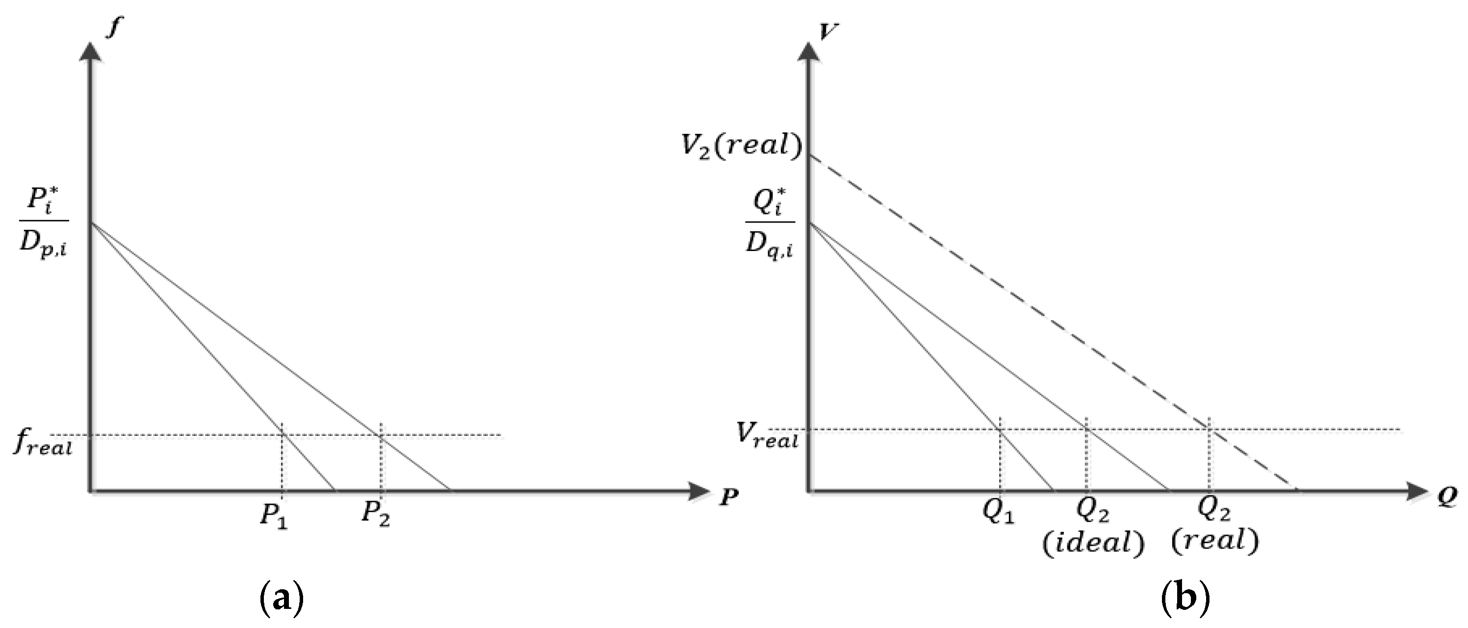
The equations conventional DG droop control are listed in Equations (1) and (2). As shown in Figure 2, the active power and reactive power information is shared among DGs based on the droop coefficients and .
Taking active power sharing as an example, the DGs’ outputs could be satisfied as the following relationship considering that the generator frequency is identical for all DGs in steady state
Equation (3) can be further simplified if the active power is chosen to be proportional to
Equation (4) indicates that the active power is proportionally shared by . Consequently, the active power sharing among DGs is totally determined by coefficients no matter how the system loads vary. Usually, the droop coefficients of DGs are chosen to be proportional to each DG’s power generation capacity. As a decentralized mechanism to effectively enforce active power sharing [24], unfortunately, the droop control is limitedly effective for the reactive power.
Consider a single-bus system with all DGs connected to the same bus labeled as “PCC”, the distribution lines between PCC and DGs are purely inductive with uniform reactance . The reactive power delivery from DGi to the PCC complies:
where is the output voltage of DGi and is the voltage at bus PCC. Note that and , therefore, the output voltage of DGs are determined by their droop control, or
where ki = X/Vi. Consequently,
Equation (6) reveals that the reactive power sharing among DGs is not only determined by their droop coefficient Dq,i but also constant coefficient ki.
Another scenario is shown in Figure 2. When DG2 is taken as an example, the solid line represents the ideal V-Q droop curve for DG2 while the dash line represents the actual V-Q droop curve for DG2. The reactive power sharing is no long necessary.
There are abundant MG control solutions proposed without communication among DGs when all DGs are connected to a single bus. According to Equation (6), for instance, the reactive power sharing issue could be resolved by properly adjusting droop coefficients Dq,i. To make the transmission line impedance predominantly inductive and uniform when transmission lines are assumed to be non-inductive or transmission line parameters are uniform or even unknown, especially, the virtual impedance loop technique can be adopted to adjust the virtual transmission line impedances [9,10,11]. In a meshed network, nevertheless, it can be shown that the communication among DGs connected to different buses is still required for accurate reactive power sharing.
2.2. Reactive Power Sharing in a Distribution Network
This section shows that accurate reactive power sharing is infeasible in a microgrid where DGs connected to different buses do not communicate with each other.
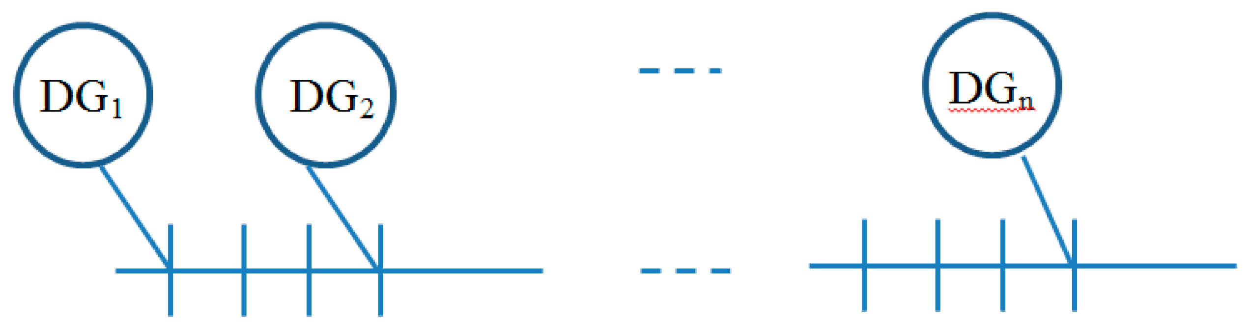
Consider the multi-bus MG shown in Figure 3; there are N DGs connected to N buses numbered from 1 to n. Suppose a load is connected to bus m (m ≤ n). Assume bus voltage magnitudes is (i = 1, 2,…, n) for DGi and line reactance of every distribution line is . Equation (7) shows the reactive power flow approximately, where Qij represents the reactive power flow from bus i to bus j. Assuming that the reactive power capacity is identical for all DGs, the control objective becomes sharing the same amount of reactive power through droop control when load varies.
Define Ii as an information set containing all information accessible to DGi. Specifically, Ii can be written as a collection of in a MG.
Proposition:
The reactive power demand will be distributed equally to DGi if and only if .
Proof:
Equation (8) suggests that the terminal voltage of DGi is required to follow to achieve the MG control objective. However, it is impractical to adjust the DG terminal voltage if the controller of DGi relies on Vj (j = 1,2,…,n) without sharing information among DGs.
In conclusion, it is required to share information among DGs connected to different buses for communication based methods to achieve accurate reactive power sharing. □
2.3. Conventional Centralized Secondary Control
The primary control and secondary control will jointly provide a reference point of voltage regulation for an inverter. For the secondary control, the objective is to regulate the frequency and voltage magnitude on the critical bus. Regarding the system structure, the secondary voltage control is usually implemented as a Central Controller (CC) requiring the voltage measurements on the critical bus. As shown in Equation (9), a control signal is generated through comparing with the reference in a PI controller. In a traditional centralized secondary control, the control signal is sent form CC to all DGs directly through communication links.
3. Basics of Consensus Control
Consensus control theory involves graph theory and system control theory. The consensus control has been broadly used in large-scale power systems, gene networks and vehicle fleets. The most important part in consensus control is the consensus protocol or agreement protocol which has been investigated comprehensively.
3.1. Directed Graph
Using to represent a directed graph consisting of nodes and edges . A node in directed graph is equivalent to an agent in consensus control; an edge in directed graph is equivalent to information flow from agent j to agent i in consensus control with weigh factor aij. The neighbors of agent i are defined as a set . An agent i can only read information from its neighbors in Ni.
The adjacency matrix of graph is defined as where if and otherwise. Correspondingly, a Laplace matrix of graph is defined as where and . In addition, a directed spanning tree of is defined as a sub-graph of . In a directed spanning tree, each node is connected from one and only one node except the root node, as shown in Figure 4.
3.2. Consensus Control Representation and Convergence
Assume each agent in consensus control as a system with single state characterized by , where is the inputs from agent ’s neighboring agents, the target of consensus control boils down to search corresponding so that the states in all agents converge to an equilibrium which is usually the average of initial states in all agents. The following consensus protocol is commonly adopted in practice:
Equation (10) can be rewritten as where is the Laplace matrix of the communication directed graph. Consensus can always be reached as long as a directed spanning tree is available for graph . The convergence is guaranteed by Theorem 1.
Theorem 1.
Consensus can be reached iff a directed spanning tree is available in the communication directed graph ; in addition, the Laplace matrix of graph will come with one and only one zero eigenvalue, while the real part of other eigenvalues will be positive.
3.3. The Concept of Leading Nodes in Consensus Control
Unusually, the target of consensus control is to converge to the average value of the initial states in all agents. However, consensus control might be required to converge to a desired state independent on initial states but dependent on external input values. With introducing a leading node to achieve this target, a control signal is delivered from the leading node to a subset of nodes . Then, the state function can be updated as:
where otherwise. Similarly, consensus can always be reached as long as a spanning tree is available for the communication directed graph . The convergence is guaranteed by Theorem 2.
Theorem 2.
The states of all agents will converge to a set point defined by the external control signal iff a directed spanning tree with root node is available in the communication directed graph .
4. Consensus-Based Hierarchical Control
In this section, a consensus-based primary and secondary control framework is proposed to solve the voltage regulation and reactive power sharing problem. Based on the discussion in Section 3, communication between DGs is required. However, sparse communication infrastructure is sufficient for the proposed framework. The sequence component analysis and the virtual impedance are used to solve the system unbalance and high R/X ratio problems.
4.1. Sequence Component Analysis
Considering that negative sequence voltage is normally caused by voltage imbalance, the voltage imbalance can be compensated by reducing the negative sequence voltage. To reduce negative sequence voltage, a sequence component analysis module is used in the droop control. The diagram of droop control with sequence component analysis is shown in Figure 5.
4.2. Virtual Impedance
Virtual impedance loop is adopted to adjust the output impedance of DGs. It is implemented right after the droop control, as shown in Figure 6. For the inverter, when the droop control output is defined as , the reference voltage becomes , where is the output current measurement and is the virtual impedance.
In a virtual impedance loop, the output voltage and output current satisfy where is the inverter terminal voltage and is the output line impedance. The equation can be derived as since the inverter a controlled voltage source holding that . The above equation suggests an equivalent view of DG as an inverter with voltage and impedance , as shown in Figure 7. As an adjustable virtual line impedance, can be chosen as inductive and large enough to make the line impedance predominantly inductive and approximated by .
4.3. Consensus Based Droop Control
To follow the consensus protocol , based on Equation (10), all states are made identical by setting the derivative of . Similarly, the reactive power can be make proportional to if s are set to be identical. Thus, a straightforward control design would be to substitute the in (10) to . A new reactive power control algorithm in Equation (12) is proposed by setting the control protocol with controllable quantity instead of .
Equation (12) can be used to make identical with proof shown as follows.
The equilibrium in Equation (12) can be obtained by setting all derivative terms to be 0
or
where is the Laplacian matrix of the communication directed graph, and . Since a directed spanning tree is available in the communication directed graph, according to Theorem 1, the rank of matrix is and must be the solution of . Consequently, the solution of Equation (14) is which can be expanded as
In other words, all ’s will converge to the equilibrium.
4.4. Consensus-Based Secondary Control
In the consensus control protocol of Equation (12), a control signal is sent to a set of agents through a sparse communication network. To send from CC to all DGs, a secondary voltage control rule based on consensus protocol is formulated in Equation (16).
where is the control signal calculated in the CC with Equation (9), is a local secondary control signal to track the CC signal with the consensus protocol in Equation (16), and represents the DGs with direct communication to the CC and otherwise. Equation (16) is in a similar form as Equation (11). According to Theorem 2, all local secondary control signals will converge to if and only if a directed spanning tree with root can communicate directly with CC in the communication directed graph. Using the proposed method in the secondary control, consequently, the communication cost could be significantly reduced.
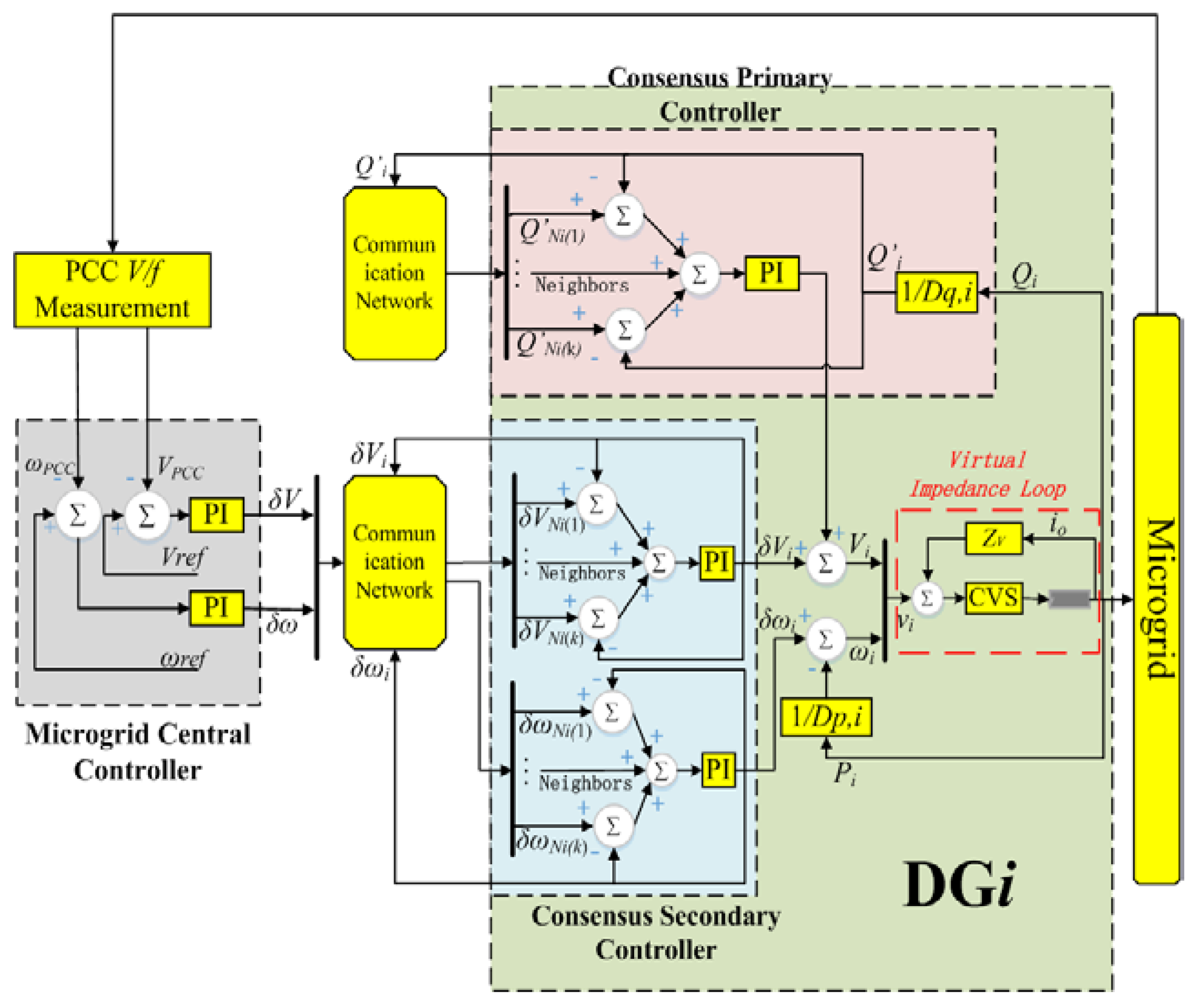
Combining the secondary control signal in Equation (17) with the primary control signal in Equation (12), the inverter voltage control law is shown below:
The block diagram of the proposed distributed voltage control law based on consensus control is visualized in Figure 8.
5. Simulation Results
5.1. Simulation Setup
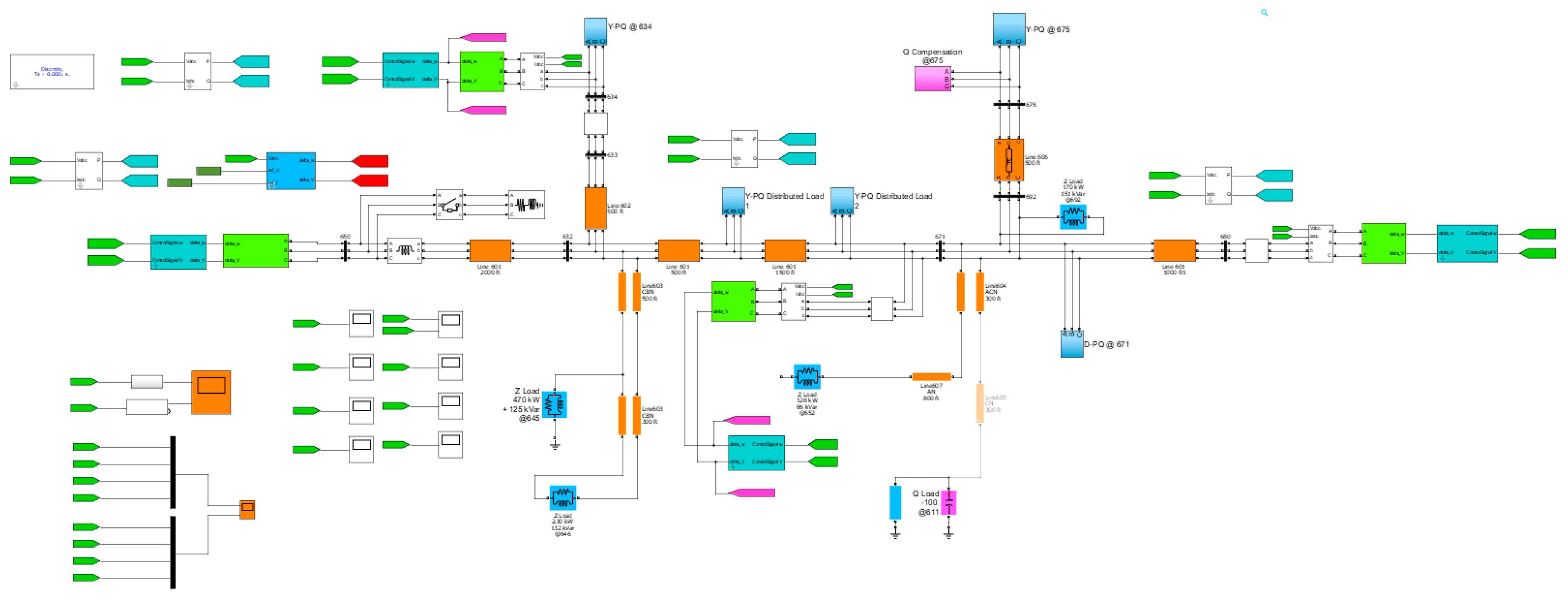
To validate the proposed control methodology, a microgrid testbed is set up, which is a modified version of the 4.16-kV IEEE standard 13-bus test feeder [25]. The testbed is shown in Figure 9. Bus 650 is selected as the critical bus, or the Point of Common Couple (PCC), whose voltage and frequency are to be regulated. The communication graph is shown in Figure 10. Simulations in this section are carried out in the Matlab/Simulink environment, using the Simscape Power System toolbox. The model built in Matlab is shown in Figure 10.
The network parameters are listed below:
There are two scenarios tested in this work, using the traditional centralized control and the proposed control, respectively:
In Scenario I, DGs adopt the conventional droop control and the centralized secondary control. Droop control parameters are listed in Table 3. Centralized secondary control parameters are listed in Table 4.
In Scenario II, DGs adopt the proposed consensus based droop control and secondary control. Control parameters are listed in Table 5.
A sudden increase of 100 + j100 kVAR each phase at t = 1.0 s is applied to the load connected to the critical bus. The outputs of active power and reactive power of all DGs along with voltage and frequency in PCC will be observed in the simulations of the above two scenarios.
5.2. Simulation Results
Simulation results of Scenario I are shown in Figure 11 and Figure 12. Simulation results of Scenario II are shown in Figure 13 and Figure 14. Measurement of power sharing for all DGs, voltage and frequency at PCC in steady state are compiled in Table 6 and Table 7 respectively. It is noted from the simulation results that:
- By comparing Figure 12 and Figure 14, only the proposed approach can realize accurate sharing of reactive power while the traditional centralized control algorithm cannot. As the control objective of the power sharing is to make sure both real and reactive power sharing among generators follows the capacities of DGs, obviously the results shown in Figure 12 do not meet this target while the results shown in Figure 14 do.
6. Conclusions
In this paper, a consensus-based primary and secondary control is proposed for voltage regulation and reactive power sharing among DGs in MGs. Communication infrastructure bandwidth requirement is low due to the nature of distribution ratio in the proposed method. Moreover, plug-and-play becomes possible in MGs because the proposed method supports flexible network topology. As reduced information exchange is required using the proposed control as compared to the traditional centralized one, the bandwidth requirement for the communication channel has been reduced significantly. As discussed in [26], consensus based distributed control is generally robust to communication latency with relatively high tolerance for delays. Lastly, the accuracy of reactive power sharing, and the performance of voltage and frequency regulation can be significantly improved by employing the proposed method.
Extension can be done to further improve this work, including but not limited to: (1) introduction of communication delay to examine/improve the robust characteristics of the proposed algorithms; and (2) adding a higher-level optimal consensus control (tertiary control) layer to make the MG an autonomous system.
Author Contributions
Conceptualization, Z.J., D.S., X.G. and L.Y.; Methodology, D.S.; Software, G.X.; Validation, C.J., L.Y. and C.J.; Formal Analysis, G.X.; Investigation, D.S.; Resources, G.X.; Data Curation, L.Y.; Writing—Original Draft Preparation, D.S.; Writing—Review and Editing, G.X.; Visualization, G.X.; Supervision, X.G.; Project Administration, Z.J.; and Funding Acquisition, C.J. and X.G.
Funding
This work was supported by China Southern Power Grid Company Limited, Development of Distribution Network Planning Software (CSGTRC-K153049).
Conflicts of Interest
The authors declare no conflict of interest.
Nomenclature
| DGi | The ith DG |
| Vi | Voltage magnitude of DGi |
| fi | Frequency of DGi |
| Dp,i | Multiplicative inverse of DGi’s active power droop coefficient |
| Dq,i | Multiplicative inverse of DGi’s reactive power droop coefficient |
| Qi* | Reference initial reactive power of DGi |
| Pi* | Reference initial active power of DGi |
| Pi | Active power output of DGi |
| Qi | Reactive power output of DGi |
| Vcb | Critical bus voltage magnitude |
| k | Constant number |
| Vstd | Microgrid nominal voltage |
| Ii | Local information set that DGi’s controller can get without interacting with other DGs |
| Ni | Neighboring buses of bus i (The set of buses that can send signals to bus i) |
| L | Laplace matrix of the communication graph |
| D | A diagonal matrix made up of each DG’s droop coefficient, |
| Q | Q = [Q1, Q2, ..., Qn]T |
| CC | The central controller |
| δV | Secondary control signal of CC |
| kP | PI controller proportional gain at CC |
| kI | PI controller integral gain at CC |
| δVi | Local secondary control variable to track the central secondary control signal δV |
| bi | Binary variable to identify whether node i is a leading node of the consensus network |
References
- Pagani, G.A.; Aiello, M. Towards decentralization: A topological investigation of the medium and low voltage grids. IEEE Trans. Smart Grid 2011, 2, 538–547. [Google Scholar] [CrossRef]
- Hatziargyriou, N.D. Microgrids management. IEEE Power Energy 2008, 6, 26–29. [Google Scholar] [CrossRef]
- Ye, Y.; Sharma, R.; Shi, D. Adaptive control of hybrid ultracapacitor-battery storage system for PV output smoothing. In Proceeding of the ASME 2013 Power Conference, Boston, MA, USA, 29 July–1 August 2013; American Society of Mechanical Engineers: New York, NY, USA, 2013; p. V002T09A015. [Google Scholar]
- Pogaku, N.; Prodanovic, M.; Green, T.C. Modeling, analysis and testing of autonomous operation of an inverter-based microgrid. IEEE Trans. Power Electron. 2007, 22, 613–625. [Google Scholar] [CrossRef]
- Guerrero, J.M.; Vásquez, J.C. Hierarchical control of droop-controlled AC and DC microgrids—A general approachtoward standardization. IEEE Trans. Ind. Electron. 2011, 58, 158–172. [Google Scholar] [CrossRef]
- Mehrizi-Sani, A.; Iravani, R. Potential-function based control of a microgrid in islanded and grid-connected models. IEEE Trans. Power Syst. 2010, 25, 1883–1891. [Google Scholar] [CrossRef]
- Bidram, A.; Davoudi, A. Hierarchical structure of microgrids control system. IEEE Trans. Smart Grid 2012, 3, 1963–1976. [Google Scholar] [CrossRef]
- Lu, X.; Guerrero, J.M.; Sun, K.; Vasquez, J.C. An improved droop control method for dc microgrids based on low bandwidth communication with dc bus voltage restoration and enhanced current sharing accuracy. IEEE Trans. Power Electron. 2014, 29, 1800–1812. [Google Scholar] [CrossRef]
- Sao, C.K.; Lehn, P.W. Autonomous load sharing of voltage source converters. IEEE Trans. Power Deliv. 2005, 20, 1009–1016. [Google Scholar] [CrossRef]
- Zhong, Q. Robust droop controller for accurate proportional load sharing among inverters operated in parallel. IEEE Trans. Ind. Electron. 2011, 58, 1281–1290. [Google Scholar] [CrossRef]
- Li, Y.W.; Kao, C.N. An accurate power control strategy for power-electronics-interfaced distributed generation units operating in a low-voltage multibus microgrid. IEEE Trans. Power Electron. 2009, 24, 2977–2988. [Google Scholar]
- Lee, C.T.; Chu, C.C.; Cheng, P.T. A new droop control method for the autonomous operation of distributed energy resource interface converters. Energy Convers. Congr. Expo. 2010, 28, 702–709. [Google Scholar]
- Guerrero, J.M.; Matas, J. Output impedance design of parallel-connected UPS inverters with wireless load-sharing control. IEEE Trans. Ind. Electron. 2005, 52, 1126–1135. [Google Scholar] [CrossRef]
- Olfati-Saber, R.; Fax, J.; Murray, R.M. Consensus and cooperation in networked multi-agent systems. Proc. IEEE 2007, 95, 215–233. [Google Scholar] [CrossRef]
- Ren, W.; Beard, R.W.; Atkins, E.M. Information consensus in multivehicle cooperative control. IEEE Control Syst. Mag. 2007, 27, 71–82. [Google Scholar]
- Bidram, A.; Davoudi, A. Secondary control of microgrids based on distributed cooperative control of multi-agent systems. IET Gener. Transm. Distrib. 2013, 7, 822–831. [Google Scholar] [CrossRef]
- Bidram, A.; Davoudi, A.; Lewis, F.L.; Guerrero, J.M. Distributed cooperative secondary control of microgrids using feedback linearization. IEEE Trans. Power Syst. 2013, 28, 3462–3470. [Google Scholar] [CrossRef]
- He, D.; Shi, D.; Sharma, R. Consensus-based distributed cooperative control for microgrid voltage regulation and reactive power sharing. In Proceedings of the IEEE Innovative Smart Grid Technologies (ISGT Europe), Istanbul, Turkey, 12–15 October 2014. [Google Scholar]
- Bidram, A.; Davoudi, A.; Lewis, F.L. A Multiobjective Distributed Control Framework for Islanded AC Microgrids. IEEE Trans. Ind. Inform. 2014, 10, 1785–1798. [Google Scholar] [CrossRef]
- Lu, L.Y.; Chu, C.C. Autonomous power management and load sharing in isolated micro-grids by consensus-based droop control of power converters. In Proceedings of the 2013 1st International Future Energy Electronics Conference (IFEEC), Tainan, Taiwan, 3–6 November 2013. [Google Scholar]
- Lu, L.Y.; Chu, C.C. Consensus-Based Droop Control Synthesis for Multiple DICs in Isolated Micro-Grids. IEEE Trans. Power Syst. 2015, 30, 2243–2256. [Google Scholar] [CrossRef]
- Matas, J.; Castilla, M.; de Vicuña, L.G.; Miret, J.; Vasquez, J.C. Virtual impedance loop for droop-controlled single-phase parallel inverters using a second-order general-integrator scheme. IEEE Trans. Power Electron. 2010, 25, 2993–3002. [Google Scholar] [CrossRef]
- Savaghebi, M.; Jalilian, A. Autonomous voltage unbalance compensation in an islanded droop-controlled microgrid. IEEE Trans. Ind. Electron. 2013, 60, 1390–1402. [Google Scholar] [CrossRef]
- Shi, D.; Sharma, R.; Ye, Y. Adaptive control of distributed generation for microgrid islanding. In Proceedings of the IEEE Innovative Smart Grid Technologies (ISGT Europe), Lyngby, Denmark, 6–9 October 2013. [Google Scholar]
- Kersting, W.H. Radial distribution test feeders. In Proceedings of the IEEE PES Winter Meeting, Columbus, OH, USA, 28 January–1 February 2001. [Google Scholar]
- Yan, Y.; Shi, D.; Bian, D. Small-signal Stability Analysis and Performance Evaluation of Microgrids under Distributed Control. IEEE Trans. Smart Grid 2018. [Google Scholar] [CrossRef]
Figure 1.
Diagram of the inverter with droop loop and secondary loop.

Figure 2.
(a) A typical P-f curve; and (b) a tdypical Q-V droop curve.

Figure 3.
A multi-bus multi-DG microgrid.

Figure 4.
A directed spanning tree of a directed graph with six nodes.

Figure 5.
Droop control for DG with sequence component analysis.

Figure 6.
Virtual Impedance Loop.

Figure 7.
Equivalent circuit after implementing the virtual impedance loop.

Figure 8.
Architecture of the distributed voltage controller based on consensus control.

Figure 9.
Microgrid test case based on IEEE 13-bus system.

Figure 10.
Microgrid system model built in Matlab/Simulink.

Figure 11.
Communication graph of proposed consensus based control.

Figure 12.
Reactive power sharing and active power sharing in Scenario I. Solid line, DG1; dash line, DG2; dash-dot line, DG3; dot line, DG4.
Figure 12.
Reactive power sharing and active power sharing in Scenario I. Solid line, DG1; dash line, DG2; dash-dot line, DG3; dot line, DG4.

Figure 13.
PCC voltage and frequency in Scenario I.

Figure 14.
Reactive power sharing and active power sharing in Scenario II. Solid line, DG1; dash line, DG2; dash-dot line, DG3; dot line, DG4.
Figure 14.
Reactive power sharing and active power sharing in Scenario II. Solid line, DG1; dash line, DG2; dash-dot line, DG3; dot line, DG4.

Figure 15.
PCC voltage and frequency in Scenario II.


Table 1.
Parameters of Transmission Lines.
| From | To | Impedance (Ohm per km) | Length (Feet) | |
|---|---|---|---|---|
| Resistance | Reactance | |||
| 650 | 632 | 0.1162 | 0.3730 | 2000 |
| 632 | 633 | 0.3700 | 0.4751 | 500 |
| 633 | 634 | 0 | 0.3770 | - |
| 632 | 645 | 1.3294 | 1.3471 | 500 |
| 645 | 646 | 1.3294 | 1.3471 | 300 |
| 632 | 671 | 0.1162 | 0.3739 | 2000 |
| 671 | 692 | - | - | - |
| 692 | 675 | 0.3046 | 0.2594 | 500 |
| 671 | 684 | 1.3238 | 1.3569 | 300 |
| 684 | 611 | 1.3292 | 1.3475 | 300 |
| 684 | 652 | 1.3425 | 0.5124 | 800 |
| 671 | 680 | 0.1162 | 0.3730 | 1000 |
Table 2.
Load Information.
| Node | Load | Ph-1 | Ph-1 | Ph-2 | Ph-2 | Ph-3 | Ph-3 |
|---|---|---|---|---|---|---|---|
| Model | kW | kVAr | kW | kVAr | kW | kVAr | |
| 634 | Y-PQ | 160 | 110 | 120 | 90 | 120 | 90 |
| 645 | Y-PQ | 0 | 0 | 170 | 125 | 0 | 0 |
| 646 | D-Z | 0 | 0 | 230 | 132 | 0 | 0 |
| 652 | Y-Z | 128 | 86 | 0 | 0 | 0 | 0 |
| 671 | D-PQ | 385 | 220 | 385 | 220 | 385 | 220 |
| 675 | Y-PQ | 485 | 190 | 68 | 60 | 290 | 212 |
| 692 | D-I | 0 | 0 | 0 | 0 | 170 | 151 |
| 611 | Y-I | 0 | 0 | 0 | 0 | 170 | 80 |
| 650 | Y | 30 | 30 | 30 | 30 | 30 | 30 |
Table 3.
Conventional Droop Control Coefficients.
| DG | Voltage Droop | |
|---|---|---|
| Qi* | Dq,i | |
| ×1011 Var | MVar/V | |
| 671 | 2.08 | 50 |
| 650 | 4.16 | 100 |
| 680 | 6.24 | 150 |
| 634 | 8.32 | 200 |
Table 4.
The Coefficients of Secondary Controllers.
| Voltage Regulation | Frequency Regulation | ||||
|---|---|---|---|---|---|
| Vref | KV,P | KV,I | fref | Kf,p | Kf,I |
| 4160 | 0.01 | 20 | 60 | 0.1 | 20 |
Table 5.
The Coefficients of Primary Controller based on Consensus Control.
| DG at Bus | Voltage Droop |
|---|---|
| kq,i | |
| Var/(Vs−1) | |
| 671 | 0.5 |
| 650 | 1.0 |
| 680 | 1.5 |
| 634 | 2.0 |
Table 6.
Summary of Simulation Results in Scenario I.
| Bus | Primary Control | Secondary Control | ||||
|---|---|---|---|---|---|---|
| Pi | Pi/P1 | Qi | Qi/Q1 | V | f | |
| kW | 1 | kVar | 1 | V | Hz | |
| 671 | 379.7 | 1.00 | 650.7 | 1.00 | ||
| 650 | 761.0 | 2.00 | 168.9 | 0.26 | ||
| 680 | 1138.1 | 3.00 | 432.7 | 0.67 | ||
| 634 | 1521.6 | 4.00 | 532.7 | 0.82 | ||
| PCC | 4160 | 60.00 | ||||
Table 7.
Summary of Simulation Results in Scenario II.
| Bus | Primary Control | Secondary Control | ||||
|---|---|---|---|---|---|---|
| Pi | Pi/P1 | Qi | Qi/Q1 | V | f | |
| kW | 1 | kVar | 1 | V | Hz | |
| 671 | 498.5 | 1.00 | 291.2 | 1.00 | ||
| 650 | 998.0 | 2.00 | 582.5 | 2.00 | ||
| 680 | 1495.1 | 3.00 | 873.8 | 3.00 | ||
| 634 | 1995.7 | 4.00 | 1165.2 | 4.00 | ||
| PCC | 416 | 60.00 | ||||
© 2018 by the authors. Licensee MDPI, Basel, Switzerland. This article is an open access article distributed under the terms and conditions of the Creative Commons Attribution (CC BY) license (http://creativecommons.org/licenses/by/4.0/).
Share and Cite
MDPI and ACS Style
Yu, L.; Shi, D.; Xu, G.; Guo, X.; Jiang, Z.; Jing, C. Consensus Control of Distributed Energy Resources in a Multi-Bus Microgrid for Reactive Power Sharing and Voltage Control. Energies 2018, 11, 2710. https://doi.org/10.3390/en11102710
AMA Style
Yu L, Shi D, Xu G, Guo X, Jiang Z, Jing C. Consensus Control of Distributed Energy Resources in a Multi-Bus Microgrid for Reactive Power Sharing and Voltage Control. Energies. 2018; 11(10):2710. https://doi.org/10.3390/en11102710
Chicago/Turabian StyleYu, Li, Di Shi, Guangyue Xu, Xiaobin Guo, Zhen Jiang, and Chaoyang Jing. 2018. "Consensus Control of Distributed Energy Resources in a Multi-Bus Microgrid for Reactive Power Sharing and Voltage Control" Energies 11, no. 10: 2710. https://doi.org/10.3390/en11102710
Note that from the first issue of 2016, this journal uses article numbers instead of page numbers. See further details here.