Optimal Modeled Six-Phase Space Vector Pulse Width Modulation Method for Stator Voltage Harmonic Suppression


1
School of Electrical Engineering and Automation, Hefei University of Technology, Hefei 230009, China
2
College of Electrical and Information Engineering, Hunan University, Changsha 410082, China
3
School of Engineering and Technology, University of Hertfordshire, Hatfield, Herts AL10 9AB, UK
4
College of Electric Engineering, Yanshan University, Qinhuangdao 066004, China
*
Author to whom correspondence should be addressed.
Energies 2018, 11(10), 2598; https://doi.org/10.3390/en11102598
Submission received: 2 September 2018
/
Revised: 24 September 2018
/
Accepted: 26 September 2018
/
Published: 29 September 2018
Abstract
:Dual Y shift 30° six-phase motors are expected to be extensively applied in high-power yet energy-effective fields, and a harmonic-suppressing control strategy plays a vital role in extending their prominent features of low losses and ultra-quiet operation. Aiming at the suppression of harmonic voltages, this paper proposes a six-phase space vector pulse width modulation method based on an optimization model, namely OM-SVPWM. First, four adjacent large vectors are employed in each of 12 sectors on a fundamental sub-plane. Second, the optimization model is constructed to intelligently determine activation durations of the four vectors, where its objective function aims to minimize the synthesis result on a harmonic sub-plane, and its constraint condition is that the synthesis result on the fundamental sub-plane satisfies a reference vector. Finally, to meet the real-time requirement, optimum solutions are obtained by using general central path following algorithm (GCPFA). Simulation and experiment results prove that, the OM-SVPWM performs around 37% better than a state-of-the-art competitive SVPWM in terms of harmonics suppression, which promise the proposed OM-SVPWM conforms to the energy-effective direction in actual engineering applications.
1. Introduction
With the explosive application of high-power equipment promoted by steady development of AC drive systems, applications of multiphase motor drive systems (MMDS) which are popular in high precision and extreme reliability occasions, have been growing dramatically in recent years [1,2,3]. Compared with conventional three-phase drive systems, in which voltage and current sharing always suffer accidents caused by series-parallel power devices, MMDS possesses notable advantages of lower torque ripple, higher fault tolerance and reliability. Meanwhile, accessibility to more phases enhances the freedom of the motor control strategy. Besides, the fundamental and harmonic components can be handled by space vector decoupling. The harmonic component control can be managed flexibly by a harmonic sub-plane, further improving the comprehensive performance of multiphase motors. Consequently, in-depth study on driving techniques of MMDS has vital theoretical and practical significance for high-power industrial applications, ranging from electric and hybrid electric vehicles to electric ship propulsion, and from locomotive traction to “more-electric” aircraft.
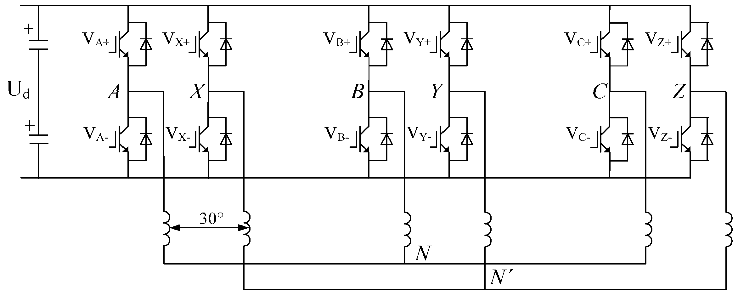
As a prominent MMDS, dual Y shift 30° six-phase motor (DYSM) has gained widespread attention and representative application in high-power yet energy-effective fields, such as electric locomotive traction, ship electric propulsion, wind power generation, etc. [4,5,6]. The stator of a DYSM has an irregular but delicate structure. As shown in Figure 1, the asymmetric six-phase windings of a DYSM are constructed with two sets of three-phase windings, which are arranged with a 30° spatial electrical angle displacement. This special structure brings the following three typical advantages: (1) With the asymmetric six-phase winding, lower-order harmonic components of the magnetic motive force can be effectively eliminated; (2) With double the number of winding phases, higher power can be transmitted on the same voltage or current level; (3) Continuous operating of DYSMs under phase-deficient conditions is possible. These advantages are highly beneficial to green power and sustainable energy-saving.
Given a determined inverter topology, a modulation strategy is extremely significant to improve the performance of a certain motor system [7,8,9]. It can be evidently investigated that, the space vector pulse width modulation (SVPWM) is the most widely applied scheme. SVPWM has attractive flexibility for optimizing switching waveforms and is convenient to implement on embedded processors [10,11], as well as its operational advantages over carrier-based techniques (i.e., low total harmonic distortion, high efficiency and voltage available in the DC-link) [12].
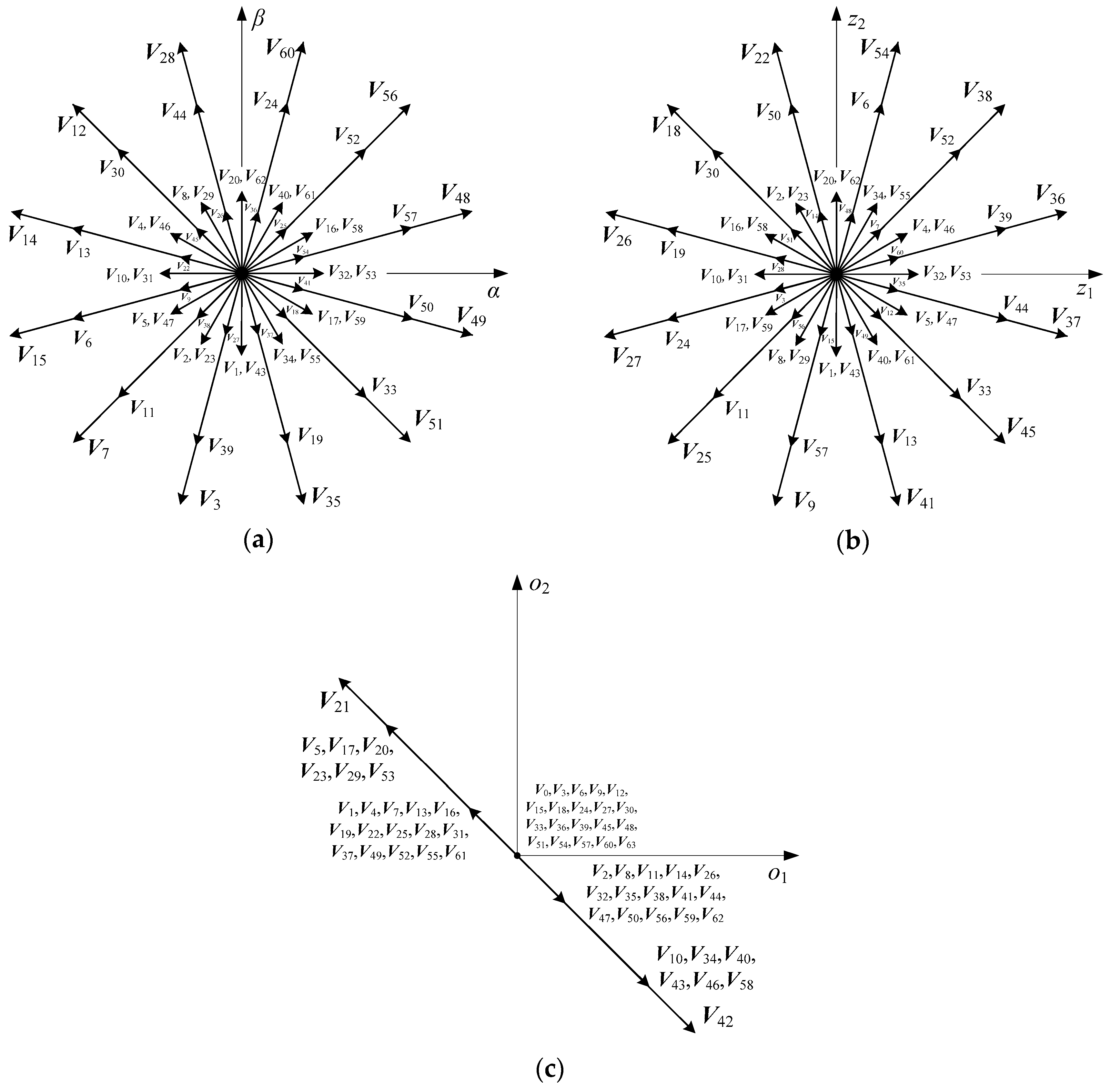
Generally, six-phase SVPWM is implemented by two basic approaches. One is vector classification control, which treats the six-phase motor as two independent three-phase motors with a phase difference of 30°, and then separately adopts three-phase SVPWM. The other, named vector space decomposition (VSD) control, is based on space vector decoupling techniques [13]. With regard to this method, except for magnifying the fundamental voltage, the stator harmonic voltage should be cautiously considered and completely suppressed. The relationship, respective features, and recommended applications of these two control methods have been extensively investigated in [14]. This paper focuses on the latter one. As shown in Figure 2, 64 phase voltages corresponding to 64 switching states of an inverter are respectively mapped to three orthogonal coordinate sub-planes: fundamental sub-plane (α-β sub-plane), harmonic sub-plane (z1-z2 sub-plane) and zero-sequence sub-plane (o1-o2 sub-plane). Then, 64 voltage vectors are generated correspondingly. The α-β sub-plane contains fundamental waves and t1th harmonic components, the z1-z2 sub-plane contains t2th harmonic components, and the o1-o2 sub-plane contains t3th harmonic components, where t1 = 12k ± 1, t2 = 12k ± 5, t3 = 12k ± 3, k = 0,1,2,3,…, The harmonics on the z1-z2 sub-plane make null contribution to motor electromechanical energy conversion but result in energy wastage, which should be suppressed as far as possible.
The past two decades have witnessed numerous developments of state-of-the-art VSD control strategies, they mainly treat the machine as an integral six-phase system [15,16,17,18,19,20]. Supposing the coordinate transformation matrix follows the principle of amplitude equivalence, the 64 fundamental vectors exhibit five different magnitudes on the α-β sub-plane: 0.644Ud (large vectors), 0.4714Ud (medium vectors), 0.2066Ud (small vectors), 0.1725Ud (ultra-small vectors), and 0 (zero vectors), where Ud denotes the DC-bus voltage of inverter. In [15], the traditional three-phase SVPWM was directly applied in six-phase motor systems, this method could track reference vectors on α-β sub-plane precisely, but leaving the harmonic elements on z1-z2 sub-plane unconsidered. Innovatively, a classical VSD-base SVPWM strategy (hereafter is referred to C-SVPWM) was proposed to limit the 5th, 7th, 17th, 19th…, harmonic elements [16]. The key idea is that the α-β sub-plane is divided into 12 equal but non-overlapping sectors, and in each sector, five vectors (i.e., four adjacent large vectors and one zero vector, where their vector synthesized results on the z1-z2 sub-plane equals to zero) are selected to track the reference vectors. Consequently, the harmonic voltages on the z1-z2 sub-plane are completely suppressed. The motor performance on current, torque and speed are satisfactory, but its fundamental amplitude of the stator winding voltage is limited below 0.57735Ud.
A mid-vector-based SVPWM strategy (hereafter is referred to M-SVPWM) was first proposed in [17]. Arbitrary three adjacent large vectors (where their vector synthesized results on the z1-z2 sub-plane equals to zero) are chosen from α-β sub-plane to synthesize one mid-vector with the fixed magnitude and position. Then 12 mid-vectors with equal magnitude and 30° phase difference can be obtained, and the reference vector is synthesized by using the 12 mid-vectors and one zero vector. Since the essence of M-SVPWM is the same as that in [16], the limitation of 0.57735Ud cannot be broken theoretically. To overcome this barrier, a six-phase pre-synthetic-vector-based SVPWM strategy (hereafter is referred to PS-SVPWM) was proposed in [18]. Three arbitrary adjacent large vectors (where their vector synthesized results on the z1-z2 sub-plane can be allowed not equal to zero) are chosen from α-β sub-plane to synthesize one variable-magnitude but position-invariant vector, which names pre-synthesized vector. Then a total of 12 pre-synthetic vectors with variable-magnitude and 30° phase difference can be obtained. And the reference vector is synthesized by using the 12 pre-synthetic vectors (but without zero vector). In PS-SVPWM, the voltage values of the fundamental amplitude of the stator winding can be as many as 2Ud/π, and the harmonic voltage suppression has been highly emphasized on the z1-z2 sub-plane. Thus, the comprehensive performance is improved to a large extent. However, the suppression degree of the harmonic voltage could be further strengthened as minimizing operation is absent among its vector synthesized results on z1-z2 sub-plane. Based on the aforementioned achievements, an optimal modeled six-phase SVPWM is proposed in this paper (hereafter is referred to OM-SVPWM). After four adjacent large vectors are selected from each sector of the 12 pre-divided sectors on the α-β sub-plane, an optimization model is constructed to optimally determine activation durations of the four selected vectors. In the model, the optimization objective is to minimize vector synthesized results on the z1-z2 sub-plane of the four selected vectors, and the constraint condition is that vector synthesized result on the α-β sub-plane of the four selected vectors satisfies a reference vector. In practical engineering applications, given every magnitude and position of the reference vector, the general central path following algorithm (GCPFA) [21] is adopted to obtain the optimum solution in real time. The rest of this paper is organized as follows: Section 2 briefly introduces the theory preliminaries of two traditional SVPWM strategies. Section 3 elaborates the theory of the proposed OM-SVPWM in detail. Theoretical simulation and real-world experiments are illustrated and discussed in Section 4. Section 5 finally concludes this paper.
2. State-of-the-Art Six-Phase SVPWM Strategies
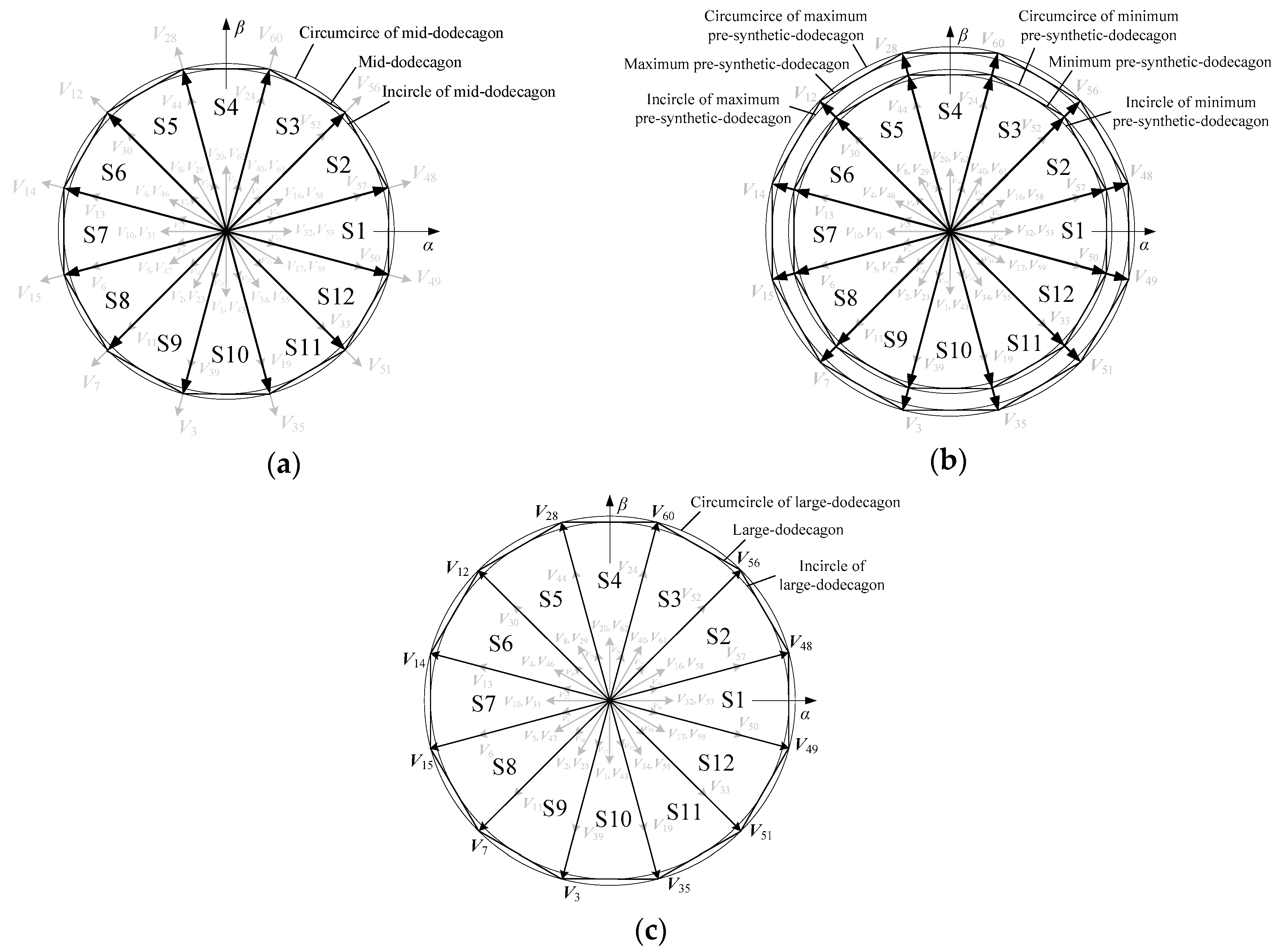
In the M-SVPWM, the 12 mid-vectors on the α-β sub-plane form a regular 12-sided shape, which is called the mid-dodecagon. Its circumcircle radius Rm is 0.5977Ud, and incircle radius rm is 0.57735Ud. With 12 mid-vectors as the boundary, the α-β sub-plane is divided into 12 sectors, expressed by S1–S12, as shown in Figure 3a. In each sector, the reference vector V* is synthesized by using two mid-vectors (i.e., the mid-vector at the initial side of the sector and the mid-vector at the terminal side of the sector) and one zero vector. Since two mid-vectors correspond to four adjacent large vectors, the reference vector is finally synthesized through five vectors (i.e., four adjacent large vectors and one zero vector). The activation durations t1, t2, t3, t4, t0 of these five vectors in a switching period Ts are:
where V* is the magnitude of reference vector, and θ is the position of reference vector (i.e., the angle between the reference vector and the mid-vector at the initial side of the sector, 0° ≤ θ ≤ 30°).
According to (1), when the value of V* exceeds the radius rm (i.e., 0.57735Ud) of the inscribed circle, the activation duration of zero vector t0 will appear negative value, so the value range of V* is 0 ≤ V* ≤ 0.57735Ud. Within this span, the synthesis result of the five vectors on the α-β sub-plane is equal to the reference vector, and the synthesis result is equal to zero on the z1-z2 sub-plane.
The PS-SVPWM can make the value of V* exceed 0.57735Ud. As shown in Figure 3b, the PS-SVPWM on the α-β sub-plane form a series of regular 12-sided shapes, called the pre-synthetic-dodecagons. The minimum pre-synthetic-dodecagon coincides with the mid-dodecagon, and the maximum pre-synthetic-dodecagon coincides with the 12-side shape formed by the 12 large vectors. Thus, the maximum circumcircle radius Rp is 0.644Ud, and the maximum incircle radius rp is 0.622Ud. With 12 pre-synthetic vectors as the boundary, the α-β sub-plane is divided into 12 sectors, which are represented by S1–S12. In each sector, the reference vector V* is synthesized by two pre-synthetic vectors (i.e., the pre-synthetic vector at the initial side of the sector and the pre-synthetic vector at the terminal side of the sector), and zero vectors are no longer involved in the synthesis. Since two pre-synthetic vectors correspond to four adjacent large vectors, the reference vector is ultimately synthesized from four adjacent large vectors. The activation durations t1, t2, t3 and t4 of the four vectors in one switching period Ts are:
where a is a proportional coefficient, which varies with the magnitude and position of reference vector; Ta is the activation duration of the pre-synthetic vector at the initial side of the sector, which varies with the position of reference vector; Tb is that at the terminal side of the sector. The specific expressions of the three parameters are as follows:
According to (2) and (3), the span of V* is 0.57735Ud ≤ V* ≤ 0.622Ud. In this span, the synthesis result of the four vectors on the α-β sub-plane is equal to the reference vector, while the synthesis result on the z1-z2 sub-plane is not equal to zero.
The above two methods are based on the six phase SVPWM of the non-optimized model. M-SVPWM can make the synthesis result of z1-z2 sub-plane to zero, but the value of V* can only reach 0.57735Ud at most; by contrast, the value of V* can reach 0.622Ud at most, but the synthesis result of z1-z2 sub-plane is not equal to zero. Therefore, in order to minimize the synthesis result of z1-z2 sub-plane and at the same time to maximize the value of V* up to 0.622Ud, the following six-phase SVPWM method based on optimization model is proposed.
3. Six-Phase SVPWM Based on Optimization Model
As shown in Figure 3c, the 12 large vectors on the α-β sub-plane form a normal 12-sided shape, called the large-dodecagon. The circumcircle radius RL is 0.644Ud, and the incircle radius rL is 0.622Ud. By using 12 large vectors as the boundary, the α-β sub-plane is divided into 12 sectors, which are represented by S1–S12. In each sector, the reference vector V* is synthesized by four adjacent large vectors, and zero vectors do not participate in the synthesis. The optimization model is as follows:
where Vh is the hth vector from four large vectors; Th is the activation duration of the hth large vector and is the design variable; is the synthesis result of four large vectors; is the magnitude of the synthesis result of four large vectors; is the sum of the four activation durations, which is equal to the switching period Ts.
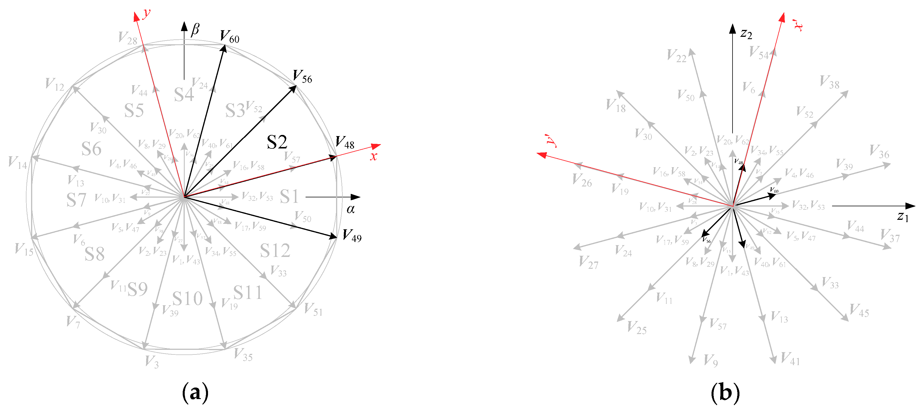
The objective function of the (4) shows that the smaller , the more effective suppression of the harmonic voltage on z1-z2 sub-plane. There are three constraints to (4): First, is equal to the reference vector on the α-β sub-plane; Second, the sum of the four activation durations is equal to one switching period; Third, the activation duration of each large vector is nonnegative. Take sector S2 as an example, the four large vectors are V49, V48, V56, V60. Then set up a local rectangular coordinate on the sector, where the horizontal axis x is consistent with the vector V48 at the initial side of the sector, as shown in Figure 4a; set up a local rectangular coordinate on the z1-z2 sub-plane, where the horizontal axis x′ is consistent with V48, as shown in Figure 4b. Therefore the objective function is:
where is the square of the projection of the four vectors synthesis result on the horizontal axis x′, and is that on the longitudinal y′.
The concrete expressions for and are as follows:
The objective function can be further simplified to:
Turn (8) into a quadratic form about t49, t48, t56 and t60 as follows:
According (9), the matrix of quadratic form is a positive semidefinite matrix. The constraint condition is:
From (8) to (10), we know that this is a convex quadratic programming (CQP) with equality constraints and inequality constraints. The CQP problem contains two parameters, the magnitude V* and position θ of the reference vector, where, 0.57735Ud ≤ V* ≤ 0.622Ud, 0° ≤ θ ≤ 30°. For each specific V* and θ, the optimal solution can be obtained by using an optimization algorithm. There are many algorithms for solving the CQP problem, but through the joint debugging of software and hardware, we find that a general central path following algorithm (GCPFA) [21] can quickly find the exact optimal solution. The situation in other sectors is similar to sector S2, so it is not repeated.
4. Simulations and Experiments
In order to evaluate the proposed OM-SVPWM synthetically, we selected the recent state-of-the-art strategy, PS-SVPWM, as a baseline, then carried out a series of quantificational simulations to verify the suppression effect on harmonics.
4.1. Simulation Results
4.1.1. Simulation 1 (Open-loop System Simulation)
The simulation model of open-loop system of six-phase inverter driving dual Y shift 30° six-phase permanent magnet synchronous motor (PMSM) is built in MATLAB/Simulink. The key simulation parameters are as follows: the number of pole pairs p = 3, the stator resistance Rs = 1.4 Ω, the straight-axis inductance Ld = 7 mH, the cross-axis inductance Lq = 7 mH, the moment of inertia J = 0.016 kg·m2, and the permanent magnet flux ψfd = 0.68 Wb. The DC bus voltage of the inverter is 300 V, and the reference vector frequency is 50 Hz. Two magnitude values, 0.6Ud, 0.622Ud, are chosen for reference vector. For clear expression, a modulation index m is introduced:
where V* is the reference vector magnitude, and Ud is the DC bus voltage. In particular, m = 0.6 if V* = 0.6Ud; m = 0.622 if V* = 0.622Ud. The motor starts and runs with non-load. Figure 5, Figure 6, Figure 7, Figure 8, Figure 9 and Figure 10 show the simulation results of the two comparative methods. The data in these figures are all based on the DC bus voltage Ud after normalized processing.
m = V*/Ud
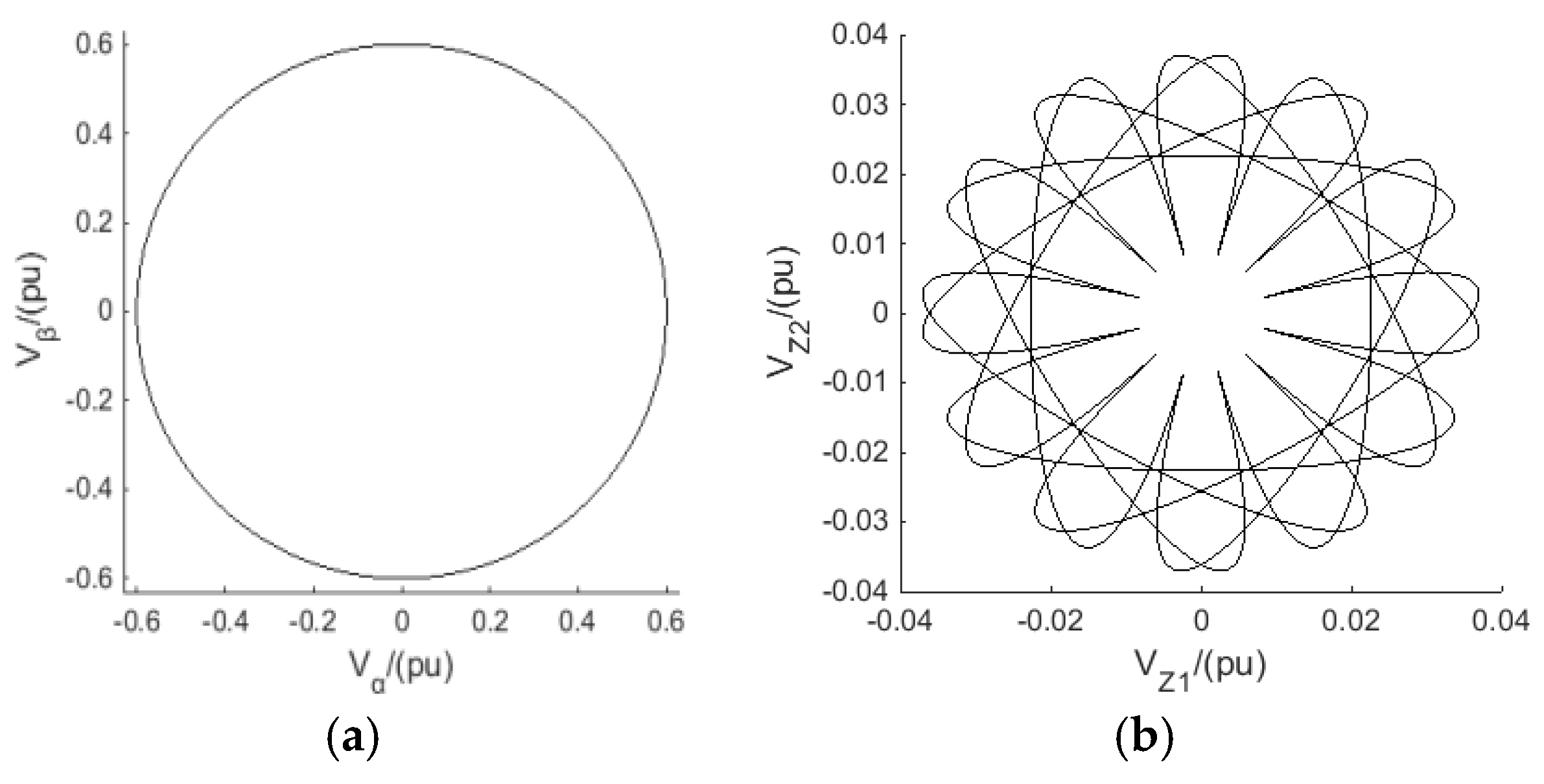
Given m = 0.6, Figure 5 shows the synthetic vectors of two methods on the α-β sub-plane and z1-z2 sub-plane. It is clearly seen that, with the same prerequisite of the synthetic vectors of the two methods, the maximum synthesized vector magnitude on the z1-z2 sub-plane of the proposed OM-SVPWM is about 25% lower than that of PS-SVPWM (0.03 vs. 0.04).
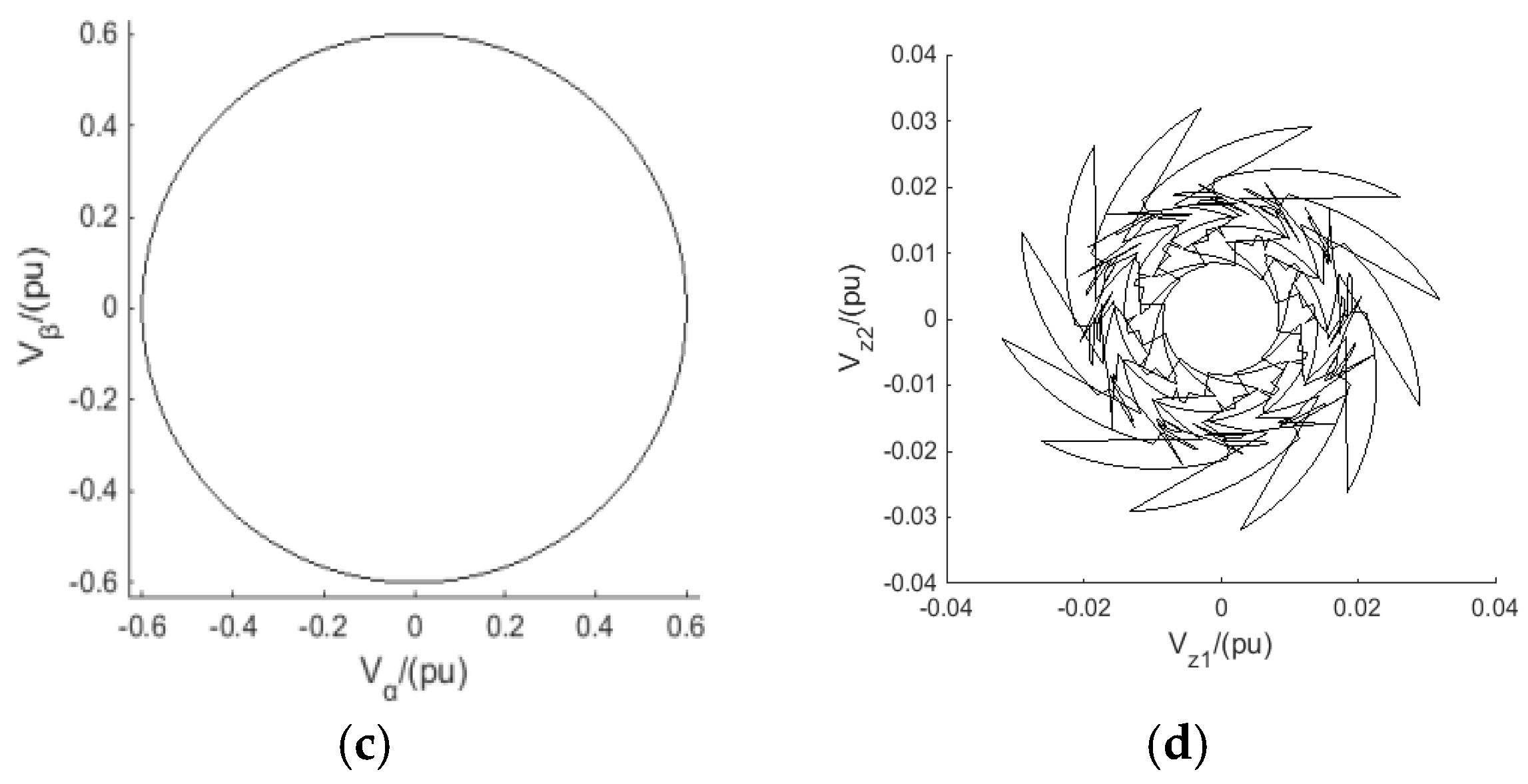
This superiority has been fully maintained on the comparison of the harmonic voltage on z1-z2 sub-plane (about 0.031 amplitude for OM-SVPWM while about 0.039 for PS-SVPWM), which can be referred to Figure 6. In particular, we continue to analyze the total harmonic distortion for voltage (THDu) for the stator A-phase windings. As shown in Figure 7, the OM-SVPWM still performs better than PS-SVPWM on THDu, with 3.36% vs. 4.97%. This improvement can further be verified in the FFT analyses between Figure 7b and Figure 7d.
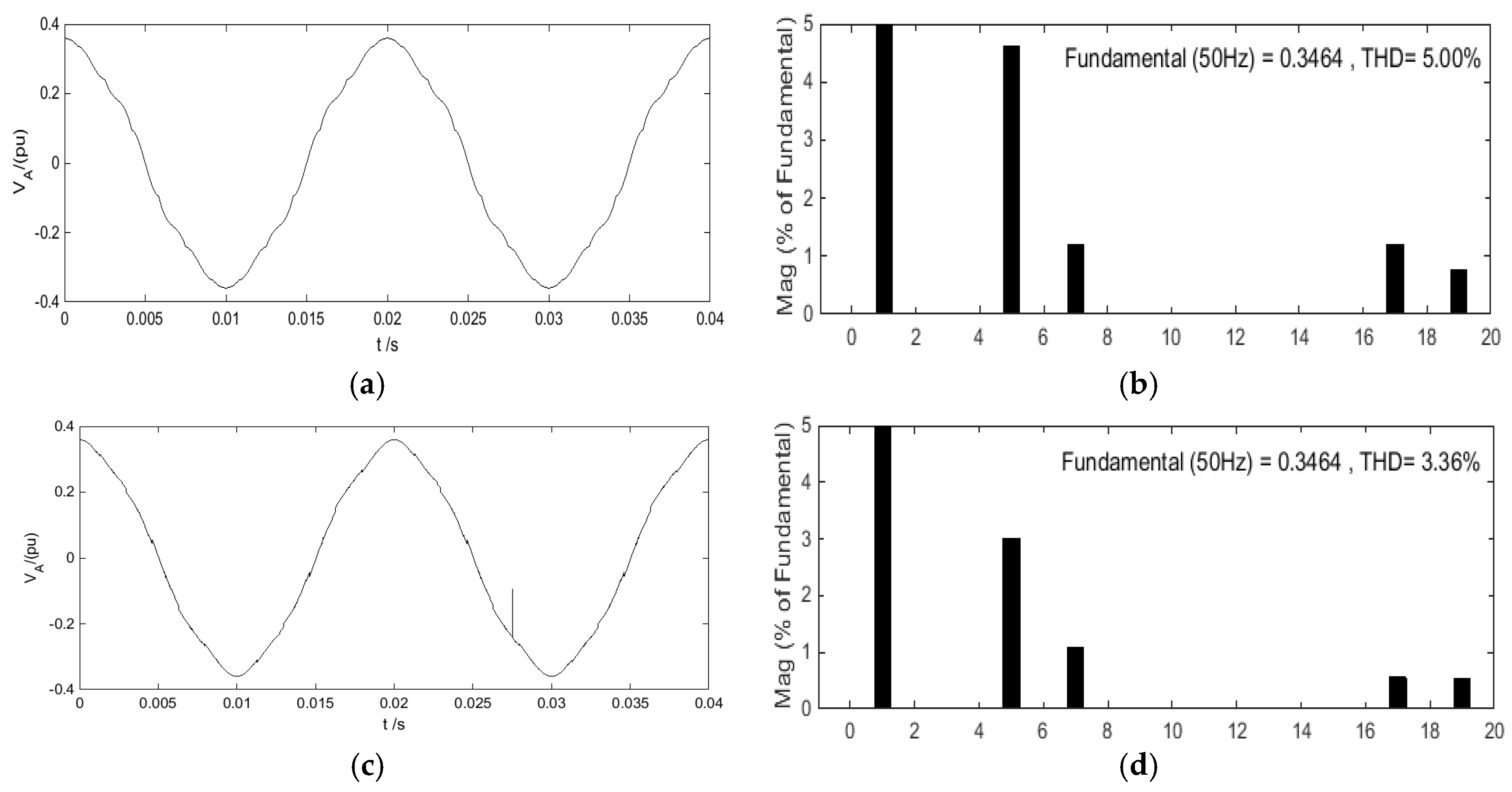
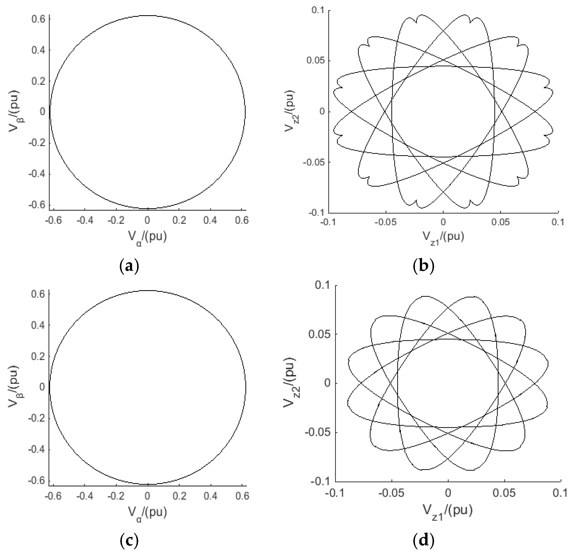
In actual practice, increasing m gains higher utilization ratio of DC voltage (power) is higher, which is benefited from the increased fundamental component of the output voltage. However, the side effect of higher m challenges more to harmonic suppression. For this consideration, a similar set of simulations is repeatedly carried with m = 0.622 to evaluate the robustness of OM-SVPWM. As shown in Figure 8, to obtain the same level of synthetic vectors on the α-β sub-plane, although both methods experience rising of harmonic components with the increase of m, our OM-SVPWM still exhibits leading advantage on the suppression degree of synthesized vector magnitude on the z1-z2 sub-plane, with 0.09 vs. 0.10. This superiority (refer to Figure 9) has been kept on the comparison of the harmonic voltage on z1-z2 sub-plane (about 0.089 amplitude for OM-SVPWM while about 0.097 for PS-SVPWM). When it comes to the comparison tests on THDu for the stator A-phase windings. As shown in Figure 10, the OM-SVPWM (THDu = 11.78%) still performs better than PS-SVPWM (THDu = 12.67%), which can be also learnt from the FFT analyses comparisons in Figure 10. In summary, no matter given friendly or tough conditions (i.e., m = 0.6 or m = 0.622), the proposed OM-SVPWM performs better than PS-SVPWM on suppression of both the amplitude and content of harmonic voltage.
4.1.2. Simulation 2 (Closed-loop System Simulation)
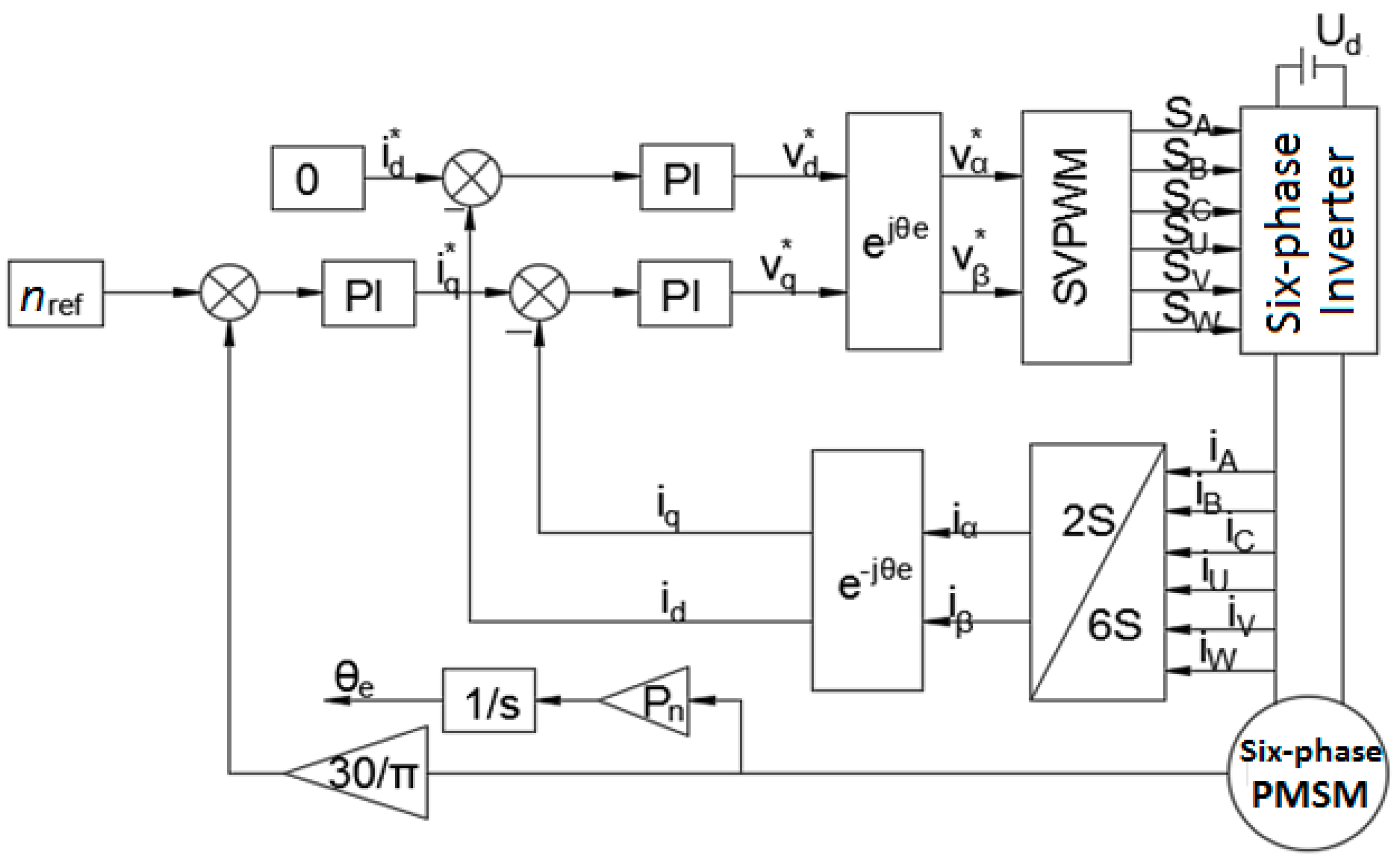
For further investigation, the OM-SVPWM and PS-SVPWM are simulated on a six-phase PMSM vector control system. The control block diagram is shown in Figure 11.
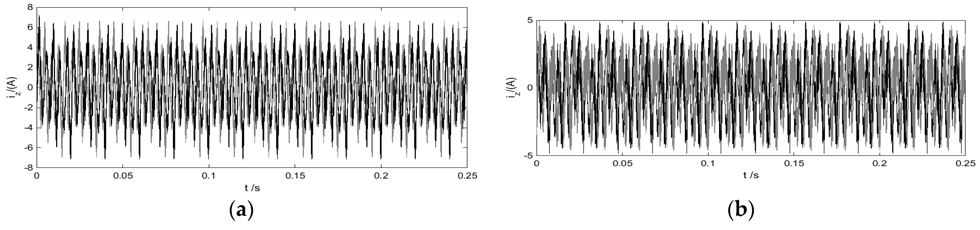
The given speed nref = 478 r/min. After starting with non-load, the motor is placed with a 50 N·m load at 0.1 s. Figure 12 gives the harmonic current simulation results on the z1-z2 sub-plane of the two methods.
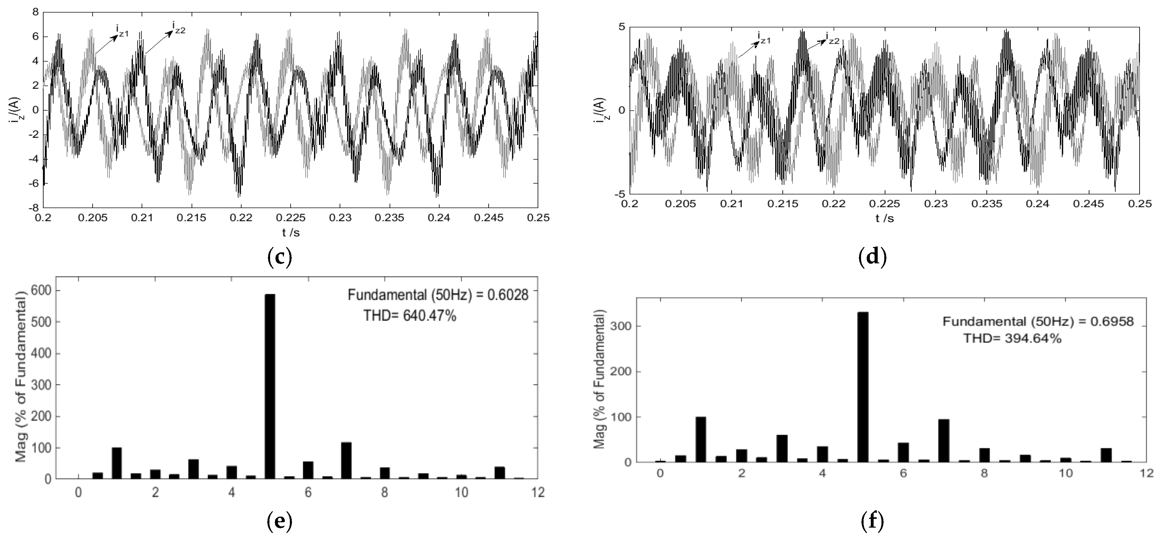
From Figure 12a–d, OM-SVPWM generates only 4.89 A amplitude of harmonic current while PS-SVPWM suffers more serious harmonic current, which is high up to 7.12 A. Figure 12c,d indicate that the frequency of the harmonic current are identical. Further from Figure 12e,f, the 5th and 7th current harmonics of OM-SVPWM are much smaller than those of PS-SVPWM. Compared with the 640.74% THDi of PS-SVPWM, our OM-SVPWM performs nearly twice better, with only 394.64% THDi. Evidently, the current harmonics of is dramatically reduced by using the proposed OM-SVPWM. Besides, it can be easily learnt from Figure 12a,b that both harmonic current are not affected when the load is applied at 0.1 s. This is because the electromechanical energy conversion only occurs in the fundamental sub-plane, and the load torque has no effect on the harmonic sub-plane currents.
4.2. Experimental Results
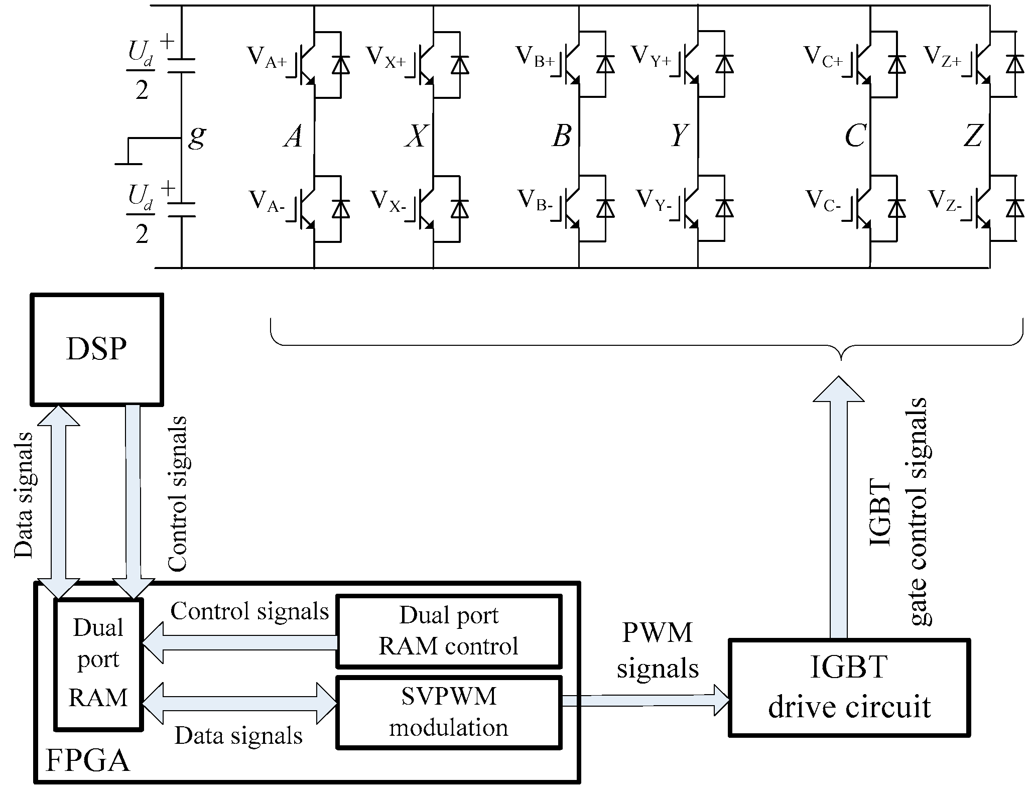
The experimental platform is mainly composed of uncontrolled rectifier bridges, voltage stabilization circuits, inverter module, IGBT drive circuits, DSP-, and FPGA-based units, as well as a dual Y shift 30° six-phase PMSM. The chip model of the adopted DSP is the TMS320F28335 (Texas Instruments, Dallas, TX, USA), which is responsible for the algorithmic dispatching and data flow control. The chip model of the adopted FPGA is EP2C5 (Altera, Santa Clara, CA, USA), which acts the coprocessor of DSP. Benefiting from the high parallel processing ability, the FPGA is in charge of hardware acceleration of massive calculations (i.e., cumulative multiplication or convolution operation). Figure 13 presents the functional block diagram. In addition, an operating status monitoring unit (OSMU) based a low-power 14-bit AD converter (chip model: ADS7945, Texas Instruments, Dallas, TX, USA) is designed for capturing the current of stator winding and the speed of PMSM. All the acquired information is processed on FPGA in parallel, the calculated results are shared to DSP through the Dual-Port RAM (DP-RAM), final computation results are transmitted to host PC via Ethernet for motor status monitoring and further data analysis.
4.2.1. Experiment 1 (Open-loop System Experiment)
This experiment is carried out on the open-loop system of six-phase inverter driving six-phase PMSM. Figure 14 gives the comparative results of the stator A-phase winding voltages under the testing conditions of frequency = 50 Hz and m = 0.6.
Figure 14a shows three curves of inverter arms by using PS-SVPWM. From top to bottom: voltage waveform, filtered voltage waveform and FFT analysis of SVPWM voltage waveform. Similarly, Figure 14b shows those of OM-SVPWM. Comparing with FFT, the 5th, 7th and 11th voltage harmonics of OM-SVPWM are evidently lower than those of PS-SVPWM. Particularly, for the 5th voltage harmonics, our OM-SVPWM experiences only 13.16 Vrms, which is nearly a half of that of PS-SVPWM (24.85 Vrms).
4.2.2. Experiment 2 (Closed-loop System Experiment)
This experimental setup adopts the vector control framework designed in Figure 11. The motor starts at no load and 50 N·m load is applied at 1 s. Figure 15 shows the captured (or calculated) current waveforms of a certain stator winding of the PMSM under test. Figure 15a illustrates four current waveforms of stator winding by using PS-SVPWM. From top to bottom: the stator A-phase winding current iA, the stator U-phase winding current iU, the α-β sub-plane current component iα and the z1-z2 sub-plane current component iz1. Figure 15b shows those of OM-SVPWM. The first two curves iA and iU are respectively current waveforms of A-phase and U-phase stator windings. Coupled by Hall Current Sensor (HCS), their current parameters can be flexibly captured by the OSMU. It is worth mentioning that, the last two corves iα and iz1 cannot be measured by HCS, which are calculated by FPGA in real time.
It is not difficult to draw the preliminary views from this comparative experiment. 1. The OM-SVPWM can track the reference vector on the α-β sub-plane as good as PS-SVPWM does, as the appearances of iα in both subfigures in Figure 15 tend to be almost identically smooth sinusoidal waves. 2. The OM-SVPWM shows much lower iz1 pulsation amplitude than PS-SVPWM (5.69 A vs. 9.08 A). The essential reason is that many synthesis ways can be followed to the reference vector on the α-β sub-plane from the four adjacent large vectors. The OM-SVPWM successes in finding the synthesis method to minimize the harmonics. In contrast, the PS-SVPWM emphasizes more on tracking the reference vector via pre-synthesized vector, but with the minimization of the synthesis results on the z1-z2 sub-plane unconsidered. Consequently, although the current of the two methods is basically the same on the α-β sub-plane, the current of OM-SVPWM is around 37% less than that of PS-SVPWM on the z1-z2 sub-plane.
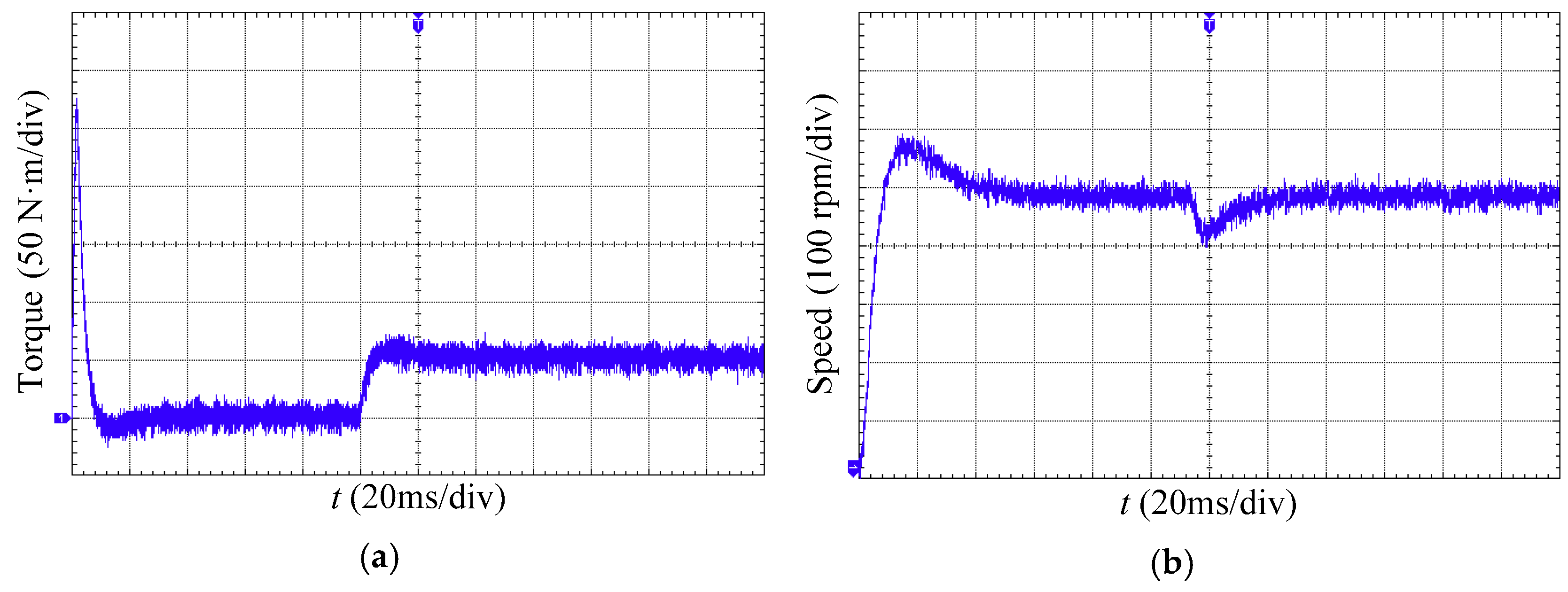
Furthermore, Figure 16 illustrates the waveforms of electromagnetic torque and rotor speed, the smooth variation trend indicates the motor operates well as both voltage and current harmonics have been suppressed to a large extent by the proposed OM-SVPWM. In summary, these preliminary results verify our initial conjecture that the minimization of synthesis vectors on z1-z2 sub-plane are indeed beneficial to stator harmonic suppression. Our proposed OM-SVPWM strategy is precisely produced for such consideration.
5. Conclusions
In the electromechanical systems composed of a dual Y shift 30° six-phase motor and two-level voltage source inverter, to further suppress the stator harmonic voltages of the motor, a novel six-phase space vector pulse width modulation based on the optimization model (OM-SVPWM) is proposed. Efficient and effective suppression to the voltage (and current) harmonics of stator windings is achieved by innovatively realized the synthesis vectors minimization on the z1-z2 sub-plane.
In the proposed optimization model, four adjacent large vectors are employed on each of 12 sectors of the fundamental sub-plane; the decision variables are the actuation durations of the four vectors; the objective function is the synthesis result of the four vectors on the harmonic sub-plane; and the constraint condition is the synthesis result of the four vectors on the fundamental sub-plane satisfies a reference vector. Essentially, the solving process of this model is a convex quadratic programming (CQP) with equality constraints and inequality constraints. With each specific magnitude and position of the reference vector, an optimal solution is obtained effectively by using a generalized central path tracking algorithm. With this generalized OM-SVPWM model, in addition to achieving intensive harmonic suppression, we realize that the fundamental amplitude of the stator winding voltage breaks through the limitation of 0.57735Ud by boosting the vector synthesized results on α-β sub-plane to a large extent. This is precisely the advantage of the optimization modelling compared with the analytical solution methods.
Experimental results from both theoretical simulation and a real-world application indicate the proposed OM-SVPWM performs better than a recent state-of-the-art strategy (PS-SVPWM) in terms of voltage and current harmonic suppression. In the open-loop simulation setup with modulation index m = 0.622, the harmonic voltage on z1-z2 sub-plane by using our OM-SVPWM is 20.51% lower than that of the PS-SVPWM, and the THDu is improved from the 12.67% of PS-SVPWM to 11.78%. In the close-loop simulation setup with motor speed nref = 478 r/min, our OM-SVPWM generates only 4.89 A amplitude of harmonic current while PS-SVPWM suffers 7.12 A, and performs nearly twice better than PS-SVPWM regarding to the THDi, experiencing only 394.64% vs. 640.74%. All these improvements have been witnessed in the actual experiments. In the open-loop experiment, OM-SVPWM experiences evidently lower than PS-SVPWM for all the 5th, 7th and 11th voltage harmonics (5th voltage harmonic: 13.16 Vrms for OM-SVPWM vs. 24.85 Vrms for PS-SVPWM). In the close-loop experiment, our OM-SVPWM performs even 37.56% better than PS-SVPWM on harmonic suppression under the premise of insuring the same synthesized results on α-β sub-plane, with iz1 pulsation amplitude 5.69 A vs. 9.08 A.
Future work will focus on improving the calculation parallelizability to solve the CQP problem of the OM-SVPWM, so as to obtain more precise approximation solution, with the hope of that the proposed method could be further extended to the SVPWM systems of five-phase, nine-phase, twelve-phase and other multi-phase motors.
Author Contributions
The research was carried out successfully with contribution from all authors.
Funding
This work was supported by the National Natural Science Foundation of China under Grant 51704089, the Anhui Provincial Natural Science Foundation of China under Grant 1808085QF190, the China Postdoctoral Science Foundation under Grant 2017M621996, the Fundamental Research Funds for the Central Universities of China under Grant JZ2018YYPY0296, the Ph.D. Special Research Fund of HFUT under Grant JZ2016HGBZ1030.
Conflicts of Interest
The authors declare no conflict of interest.
References
- Umesh, B.S.; Sivakumar, K. Multilevel inverter scheme for performance improvement of pole-phase-modulated multiphase induction motor Drive. IEEE Trans. Ind. Electron. 2016, 63, 2036–2043. [Google Scholar] [CrossRef]
- Chappuis, B.; Gavin, S.; Rigazzi, L.; Carpita, M. Speed control of a multiphase active way linear motor based on back EMF estimation. IEEE Trans. Ind. Electron. 2015, 62, 7299–7308. [Google Scholar] [CrossRef]
- Tang, X.; Lai, C.; Liu, Z.; Zhang, M. A SVPWM to eliminate common-mode voltage for multilevel inverters. Energies 2017, 10, 715. [Google Scholar] [CrossRef]
- Levi, E. Advances in converter control and innovative exploitation of additional degrees of freedom for multiphase machines. IEEE Trans. Ind. Electron. 2016, 63, 433–448. [Google Scholar] [CrossRef]
- Xu, P.; Feng, J.H.; Guo, S.Y.; Feng, S.; Chu, W.; Ren, Y.; Zhu, Z.Q. Analysis of dual three-phase permanent-magnet synchronous machines with different angle displacements. IEEE Trans. Ind. Electron. 2018, 65, 1941–1954. [Google Scholar] [CrossRef]
- Zheng, P.; Wu, F.; Lei, Y.; Sui, Y.; Yu, B. Investigation of a novel 24-slot/14-pole six-phase fault-tolerant modular permanent-magnet in-wheel motor for electric vehicles. Energies 2013, 6, 164–176. [Google Scholar] [CrossRef]
- Li, X.; Akin, S.D.B.; Rajashekara, K. A new active fault-tolerant SVPWM strategy for single-phase faults in three-phase multilevel converters. IEEE Trans. Ind. Electron. 2015, 62, 3955–3965. [Google Scholar] [CrossRef]
- Moranchel, M.; Huerta, F.; Sanz, I.; Bueno, E.; Rodríguez, F.J. A Comparison of modulation techniques for modular multilevel converters. Energies 2016, 9, 1091. [Google Scholar] [CrossRef]
- Zheng, J.; Huang, S.; Rong, F.; Lye, M. Six-phase space vector PWM under stator one-phase open-circuit fault condition. Energies 2018, 11, 1796. [Google Scholar] [CrossRef]
- Lopez, O.; Alvarez, J.; Malvar, J.; Yepes, A.G.; Vidal, A.; Baneira, F.; Estevez, D.P.; Freijedo, F. Space vector PWM with common-mode voltage elimination for multiphase drives. IEEE Trans. Power Electron. 2016, 31, 8151–8161. [Google Scholar] [CrossRef]
- Liu, Z.; Wang, Y.; Tan, G.J.; Li, H.; Zhang, Y.F. A novel SVPWM algorithm for five-level active neutral-point-clamped converter. IEEE Trans. Power Electron. 2016, 31, 3859–3866. [Google Scholar] [CrossRef]
- Chen, K.; Xie, Y. Multiphase optimal injection PWM with dual carrier frequency to reduce current THD. IET Power Electron. 2017, 10, 1061–1077. [Google Scholar] [CrossRef]
- Ariff, E.A.R.E.; Dordevic, O.; Jones, M. A space vector PWM technique for a three-level symmetrical six phase drive. IEEE Trans. Ind. Electron. 2017, 64, 8396–8405. [Google Scholar] [CrossRef]
- Hu, Y.S.; Zhu, Z.Q.; Odavic, M. Comparison of two-individual current control and vector space decomposition control for dual three-phase PMSM. IEEE Trans. Ind. Appl. 2017, 53, 4483–4492. [Google Scholar] [CrossRef]
- Komrska, T.; Glasberger, T.; Peroutka, Z. Universal PWM modulator for multiphase drives with a minimum infinity-norm approach. IEEE Trans. Ind. Electron. 2016, 63, 5979–5987. [Google Scholar] [CrossRef]
- Zhao, Y.; Lipo, T.A. Space vector PWM control of dual three-phase induction machine using vector space decomposition. IEEE Trans. Ind. Appl. 1995, 31, 1100–1109. [Google Scholar] [CrossRef]
- Li, S.; Xiao, H.; Chen, H. The research of SVPWM control technique of double three-phase induction machine. In Proceedings of the 2005 International Conference on Electrical Machines and Systems, Nanjing, China, 27–29 September 2005; pp. 109–114. [Google Scholar]
- Yang, J.; Yang, G.; Li, T. PWM techniques for six-phase voltage-source inverters. Trans. China Electrotech. Soc. 2012, 27, 205–211. [Google Scholar]
- Zhou, C.; Yang, G.; Su, J. PWM Strategy with minimum harmonic distortion for dual three-phase permanent-magnet synchronous motor drives operating in the overmodulation region. IEEE Trans. Power Electron. 2015, 31, 1367–1380. [Google Scholar] [CrossRef]
- Wang, C.; Wang, K.; You, X. Research on synchronized SVPWM strategies under low switching frequency for six-phase VSI-Fed asymmetrical dual stator induction machine. IEEE Trans. Ind. Electron. 2016, 63, 6767–6776. [Google Scholar] [CrossRef]
- Chen, D.; Zhang, M. General central path following algorithm for horizontal linear complementarity problem. Math. Appl. 2011, 24, 304–311. [Google Scholar]
Figure 1.
Six-phase drive system composed of dual Y shift 30° six-phase motor and inverter.

Figure 2.
Basic voltage vectors of six-phase inverter. (a) Voltage vectors on α-β sub-plane; (b) Voltage vectors on z1-z2 sub-plane; (c) Voltage vectors on o1-o2 sub-plane.
Figure 2.
Basic voltage vectors of six-phase inverter. (a) Voltage vectors on α-β sub-plane; (b) Voltage vectors on z1-z2 sub-plane; (c) Voltage vectors on o1-o2 sub-plane.

Figure 3.
Mid-dodecagon, pre-synthetic-dodecagon and large-dodecagon on α-β sub-plane. (a) Mid-dodecagon; (b) Pre-synthetic-dodecagon; (c) Large-dodecagon.
Figure 3.
Mid-dodecagon, pre-synthetic-dodecagon and large-dodecagon on α-β sub-plane. (a) Mid-dodecagon; (b) Pre-synthetic-dodecagon; (c) Large-dodecagon.

Figure 4.
Local rectangular coordinates on two sub-planes (taking sector S2 as an example). (a) Local rectangular coordinate on α-β sub-plane; (b) Local rectangular coordinate on z1-z2 sub-plane.
Figure 4.
Local rectangular coordinates on two sub-planes (taking sector S2 as an example). (a) Local rectangular coordinate on α-β sub-plane; (b) Local rectangular coordinate on z1-z2 sub-plane.

Figure 5.
Synthetic vectors of two methods on α-β and z1-z2 sub-planes (m = 0.6). (a) Synthetic vectors of PS-SVPWM on α-β sub-plane; (b) Synthetic vectors of PS-SVPWM on z1-z2 sub-plane; (c) Synthetic vectors of OM-SVPWM on α-β sub-plane; (d) Synthetic vectors of OM-SVPWM on z1-z2 sub-plane.
Figure 5.
Synthetic vectors of two methods on α-β and z1-z2 sub-planes (m = 0.6). (a) Synthetic vectors of PS-SVPWM on α-β sub-plane; (b) Synthetic vectors of PS-SVPWM on z1-z2 sub-plane; (c) Synthetic vectors of OM-SVPWM on α-β sub-plane; (d) Synthetic vectors of OM-SVPWM on z1-z2 sub-plane.


Figure 6.
Harmonic voltage of two methods on z1-z2 sub-plane (m = 0.6). (a) PS-SVPWM; (b) OM-SVPWM.

Figure 7.
Average voltages of stator A-phase windings and their FFT analyses of two methods (m = 0.6). (a) Average voltages of stator A-phase windings and their (b) FFT analyses of PS-SVPWM; (c) Average voltages of stator A-phase windings and their (d) FFT analyses of OM-SVPWM.
Figure 7.
Average voltages of stator A-phase windings and their FFT analyses of two methods (m = 0.6). (a) Average voltages of stator A-phase windings and their (b) FFT analyses of PS-SVPWM; (c) Average voltages of stator A-phase windings and their (d) FFT analyses of OM-SVPWM.

Figure 8.
Synthetic vectors of two methods on α-β and z1-z2 sub-planes (m = 0.622). (a) Synthetic vectors of PS-SVPWM on α-β sub-plane; (b) Synthetic vectors of PS-SVPWM on z1-z2 sub-plane; (c) Synthetic vectors of OM-SVPWM on α-β sub-plane; (d) Synthetic vectors of OM-SVPWM on z1-z2 sub-plane.
Figure 8.
Synthetic vectors of two methods on α-β and z1-z2 sub-planes (m = 0.622). (a) Synthetic vectors of PS-SVPWM on α-β sub-plane; (b) Synthetic vectors of PS-SVPWM on z1-z2 sub-plane; (c) Synthetic vectors of OM-SVPWM on α-β sub-plane; (d) Synthetic vectors of OM-SVPWM on z1-z2 sub-plane.

Figure 9.
Harmonic voltage of two methods in z1-z2 sub-plane (m = 0.622). (a) PS-SVPWM; (b) OM-SVPWM.
Figure 9.
Harmonic voltage of two methods in z1-z2 sub-plane (m = 0.622). (a) PS-SVPWM; (b) OM-SVPWM.
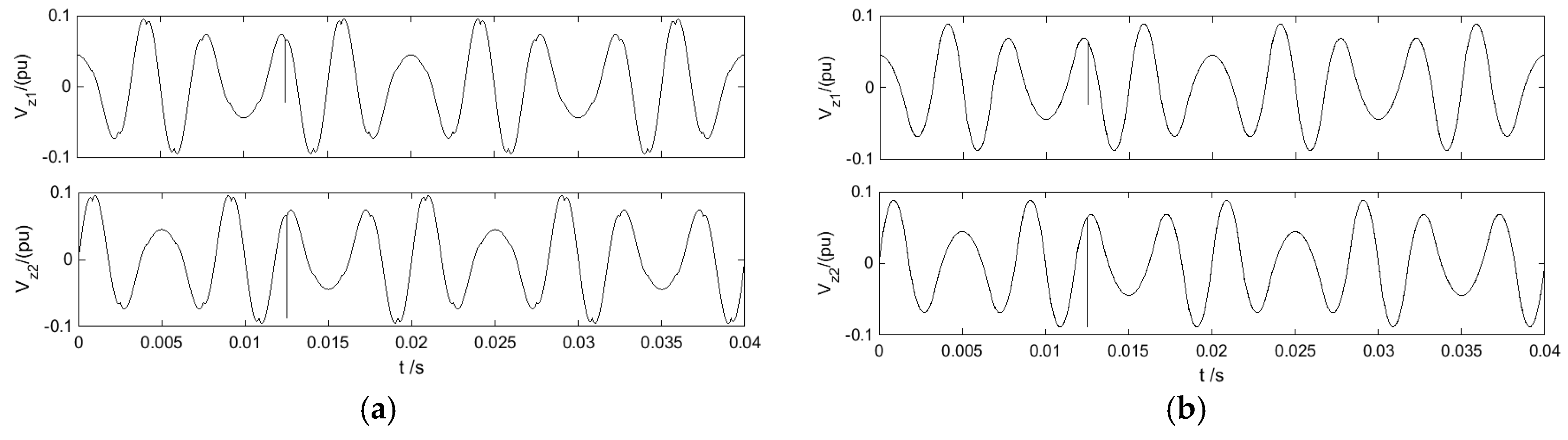
Figure 10.
Average voltages of stator A-phase windings and their FFT analyses of two methods (m = 0.622). (a) Average voltages of stator A-phase windings and their (b) FFT analyses of PS-SVPWM; (c) Average voltages of stator A-phase windings and their (d) FFT analyses of OM-SVPWM.
Figure 10.
Average voltages of stator A-phase windings and their FFT analyses of two methods (m = 0.622). (a) Average voltages of stator A-phase windings and their (b) FFT analyses of PS-SVPWM; (c) Average voltages of stator A-phase windings and their (d) FFT analyses of OM-SVPWM.
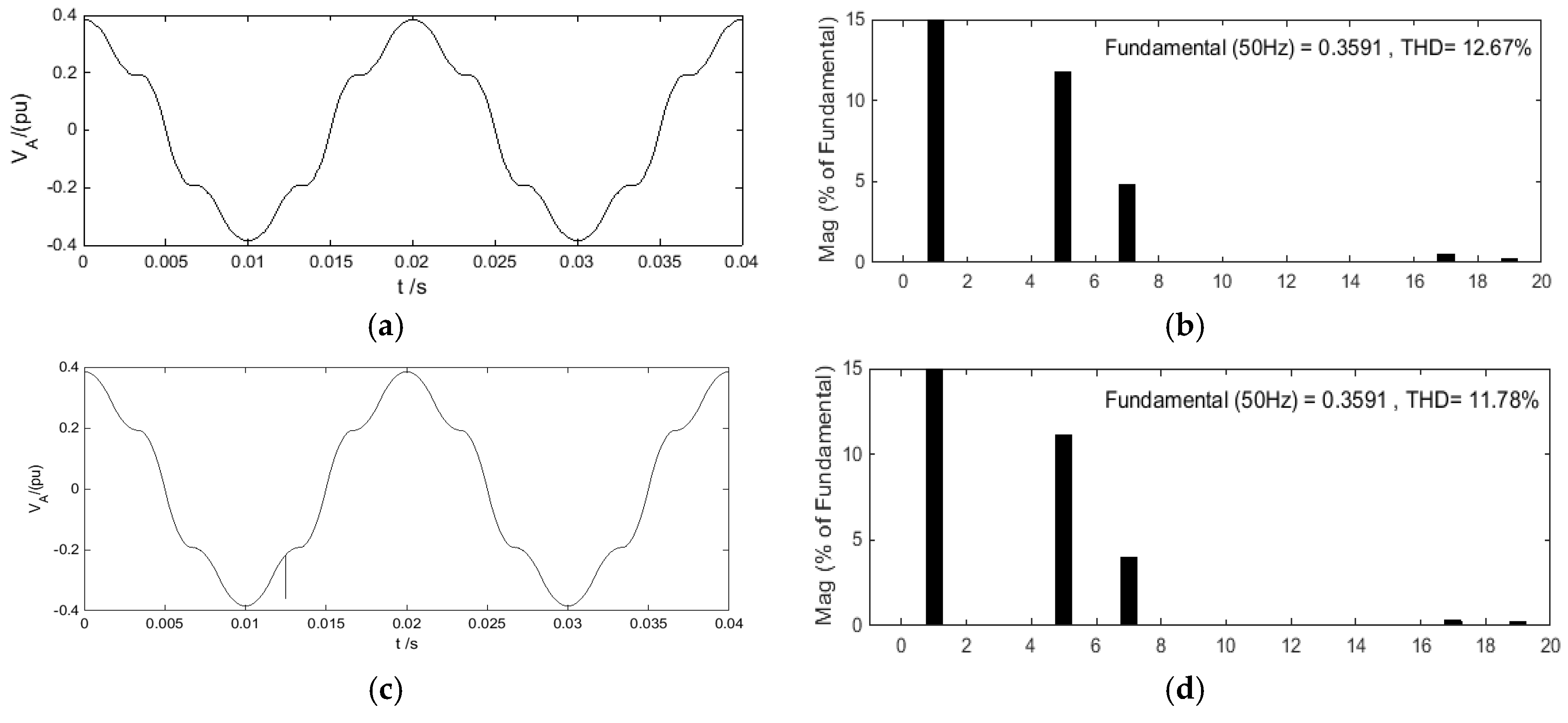
Figure 11.
Vector control block diagram of dual Y shift 30° six-phase PMSM.

Figure 12.
Harmonic currents of two methods on z1-z2 sub-plane. (a) z1-z2 sub-plane current of PS-SVPWM; (b) z1-z2 sub-plane current of OM-SVPWM; (c) z1-z2 sub-plane current (zoom) of PS-SVPWM; (d) z1-z2 sub-plane current (zoom) of OM-SVPWM; (e) FFT analysis of z1-axis current of PS-SVPWM; (f) FFT analysis of z1-axis current of OM-SVPWM.


Figure 13.
Experimental platform architecture.

Figure 14.
Stator A-phase winding voltages and their FFT analyses of two methods when m = 0.6. (a) PS-SVPWM; (b) OM-SVPWM.
Figure 14.
Stator A-phase winding voltages and their FFT analyses of two methods when m = 0.6. (a) PS-SVPWM; (b) OM-SVPWM.
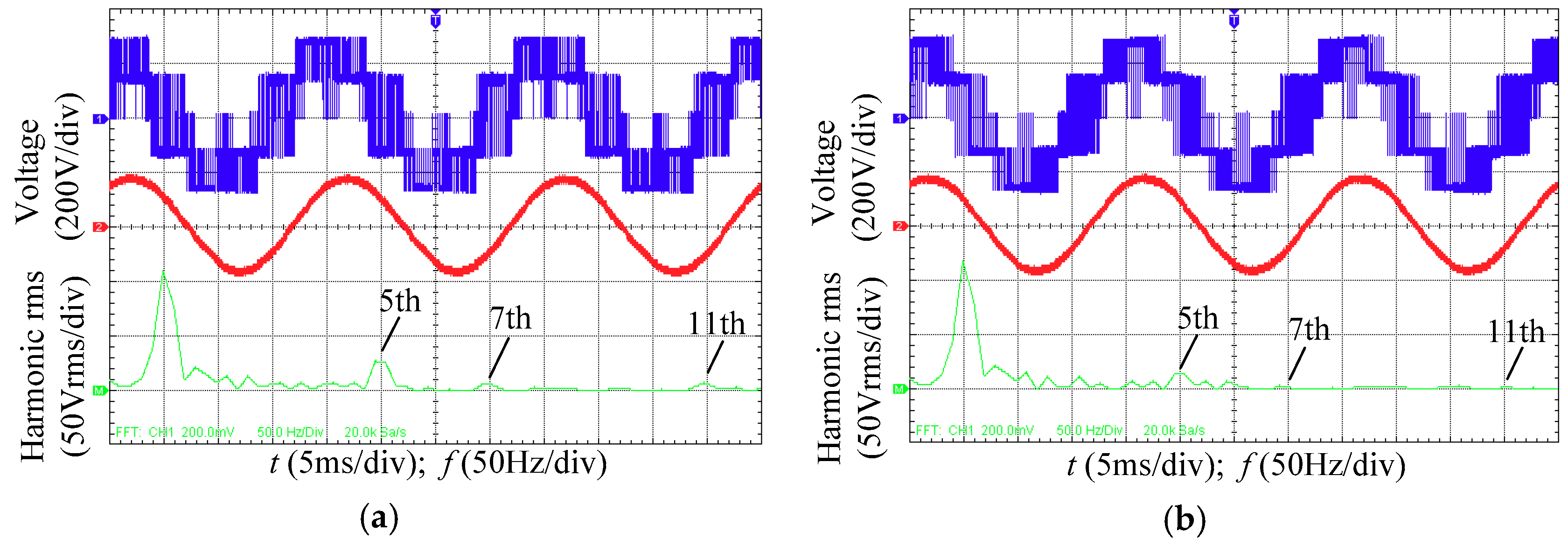
Figure 15.
Experimental results of current of two methods. (a) PS-SVPWM; (b) OM-SVPWM.
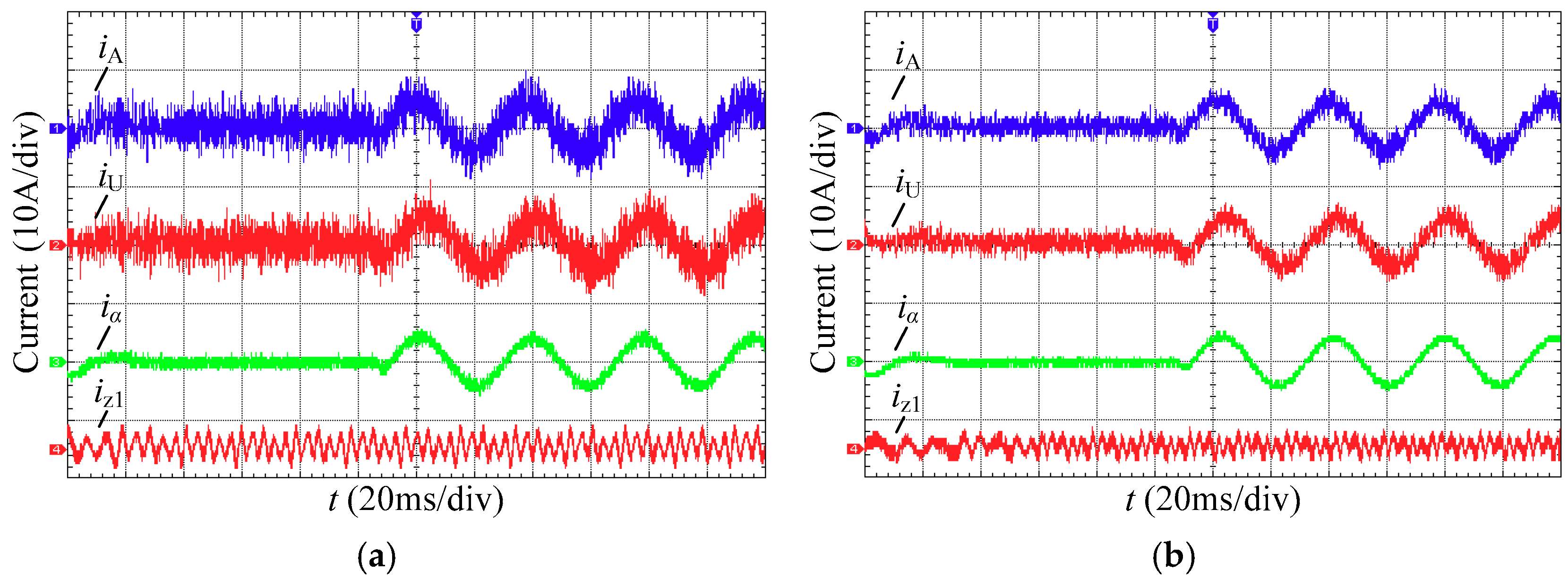
Figure 16.
Operation parameters of PMSM by using OM-SVPWM. (a) Electromagnetic torque; (b) Rotor Speed.
Figure 16.
Operation parameters of PMSM by using OM-SVPWM. (a) Electromagnetic torque; (b) Rotor Speed.
© 2018 by the authors. Licensee MDPI, Basel, Switzerland. This article is an open access article distributed under the terms and conditions of the Creative Commons Attribution (CC BY) license (http://creativecommons.org/licenses/by/4.0/).
Share and Cite
MDPI and ACS Style
Luo, Q.; Zheng, J.; Sun, Y.; Yang, L. Optimal Modeled Six-Phase Space Vector Pulse Width Modulation Method for Stator Voltage Harmonic Suppression. Energies 2018, 11, 2598. https://doi.org/10.3390/en11102598
AMA Style
Luo Q, Zheng J, Sun Y, Yang L. Optimal Modeled Six-Phase Space Vector Pulse Width Modulation Method for Stator Voltage Harmonic Suppression. Energies. 2018; 11(10):2598. https://doi.org/10.3390/en11102598
Chicago/Turabian StyleLuo, Qiwu, Jian Zheng, Yichuang Sun, and Lijun Yang. 2018. "Optimal Modeled Six-Phase Space Vector Pulse Width Modulation Method for Stator Voltage Harmonic Suppression" Energies 11, no. 10: 2598. https://doi.org/10.3390/en11102598
Note that from the first issue of 2016, this journal uses article numbers instead of page numbers. See further details here.