Article

Numerical Modeling of Dynamic Behavior and Steering Ability of a Bottom Hole Assembly with a Bent-Housing Positive Displacement Motor Under Rotary Drilling Conditions

1
State Key Laboratory of Oil & Gas Reservoir Geology and Exploitation, Southwest Petroleum University, Chengdu 610500, Sichuan, China
2
Exploration Division of PetroChina Southwest Oil & Gas Field Company, Chengdu 610041, Sichuan, China
*
Authors to whom correspondence should be addressed.
Energies 2018, 11(10), 2568; https://doi.org/10.3390/en11102568
Submission received: 13 August 2018 / Revised: 13 September 2018 / Accepted: 25 September 2018 / Published: 26 September 2018
(This article belongs to the Special Issue Geothermal Energy: Utilization and Technology 2018)

Abstract

:
Fully rotary drilling is one of many useful technologies used for the exploitation of petroleum and geothermal resources, but fully rotating drill-strings are extremely complicated. Therefore, according to the Hamilton principle, a non-linear coupled bottom hole assembly (BHA)-bit-formation-wellbore model is proposed for BHAs with bent-housing positive displacement motor using the finite element method to investigate the dynamic behavior and steering ability under fully rotary drilling. The impact force, acceleration, axial loading, torque, and dynamic stress were simulated, and factors influencing the dynamic steering forces were investigated. The results indicate that the impact force, acceleration, axial loading, torque, and dynamic stress under fully rotary drilling are much higher than under conventional drilling. The numerical simulation and field test in well B confirmed that the rotation of the drill-string is conducive to the hold-on of the deviation angle. With the increase in the weight-on-bit, bend angle, and stabilizer height, the deflecting force on a drill bit increases. Conversely, with the increase in stabilizer diameter, the deflecting force on the drill bit decreases; the lower the deflecting force, the better the effectiveness of hold-on. With increasing deviation angle, the deflecting force on the drill bit first decreases and then increases. The present model can provide a theoretical basis for wellbore trajectory control and optimization design of BHA.

1. Introduction

In order to exploit and utilize deep Earth energies and resources such as petroleum, water, geothermal, mining, and geo-energy, we need new technologies to extract these energies and resources from deep formations. The key to the exploitation and use of deep earth energies and resources is constructing a high-quality underground passage, often achieved via drilling a hole in the petroleum industry. A variety of aspects are involved in drilling, such as how to improve drilling efficiency and control the borehole trajectory as desired. Fully rotary drilling addresses both of these issues.
In oil and gas drilling engineering, fully rotary drilling refers to the combined movements of the rotary table and down-hole motor [1]. Industrial down-hole motors can be classified into two categories: the positive displacement motor (PDM), and the turbo-drill. Of the two, the PDM is the most common and the most widely used down-hole motor [2]. Due to the popularization and application of polycrystalline diamond compact (PDC) bits, drilling combining the PDM tool and PDC bit was employed to improve drill efficiency. In general, there are two kinds of drilling modes: sliding drilling, and rotary drilling. Sliding drilling is mainly used to control the well trajectory, so it can be used for drilling in the build-up section, drop-off section, and azimuth adjustment section. Rotary drilling, a kind of fully rotary drilling method, is mainly utilized to improve drill efficiency by reducing excessive drag of the drill-string, improving borehole cleaning, improving the control of the weight-on-bit (WOB), and increasing the rate of penetration (ROP); thus, it can be used for drilling in the vertical section, hold-on section, and horizontal section. Currently, drilling that combines the PDM tool and PDC bit is still the main method used to drill a directional well [1,2]. In addition, fully rotary drilling can also be employed in speedup activities of deep wells.
A large number of field applications have demonstrated that BHA with bent-housing PDM tool can increase the ROP, shorten nonproductive time (NPT), shorten drilling cycle, and reduce drilling costs [3,4,5,6]. However, the applications of fully rotary drilling using bent-housing PDM tool has created some new challenges [6,7]. Firstly, the bent-housing PDM tool has to bear alternating loads during rotary drilling, due to the special structure of the bent-housing PDM tool. Consequently, the PDM tool is prone to failure, causing downhole accidents, and thereby increasing the risk of drilling operation. Secondly, during the process of directional drilling, slide drilling and rotary drilling have to be frequently switched to control the well trajectory and to overcome the excessive drag of drill-string. “Small steps”, which affect the tortuosity of the wellbore, are easily formed, resulting in the decrease of the borehole quality. Thirdly, the impact of drill-string rotation on the mechanical behavior and steering ability of BHA with bent-housing PDM is not well understood. In fact, the mechanical model of BHA is no longer static or quasi-static but should be dynamic. Thus, the dynamic behavior and dynamic steering ability should be investigated to precisely control the well trajectory. Lastly, the impact of bit-formation interaction and drill0string-wellbore interaction on the mechanical behavior and steering ability of BHA with bent-housing PDM is not clear. In fact, the mechanical behavior and steering ability of BHA is affected by bit-formation interaction, and its influence should be involved.
The above problems are related to the mechanical behavior and steering ability of BHA with bent-housing PDM under rotary drilling. In order to achieve fast, accurate, and economical control of the wellbore trajectories in oil and gas wells, the mechanical behavior and steering ability of the BHA are key. Many scholars have therefore conducted studies on the mechanical behavior and steering ability of the BHA. Since the first mechanical model of the BHA was proposed by Lubinski and Woods [8], the development of the BHA mechanical model has advanced from an analytical to a numerical model, from a two-dimensional (2D) to a three-dimensional (3D) model, and from a static to a dynamic model [1]. Some related books introduced the systematic models and methods for the BHA, such as Developments in Petroleum Engineering (Volume I) [9], Developments in Petroleum Engineering (Volume II) [10], and Deviation Control Theory and Practice [11]. These books discuss the factors influencing the inclination angle and doglegs in rotary drilling holes, and how to control the inclination and BHA performance prediction [12]. However, most of them mainly investigated static or quasi-static mechanical behavior and the steering ability of conventional multi-stabilizer BHA and conventional BHA with a PDM tool [1]. Regarding the dynamic behavior and steering ability of BHA with bent-housing PDM, Dykstra [13] investigated the dynamic behavior of BHA by using the dynamic model of a rotor. The dynamic model of BHA was proposed on the basis of the Hamilton principle. Liu et al. [14] introduced an arc bent beam unit and dynamic gap element. The arc bent beam units and rigidity matrix were suited to the deformation analysis of a drill-string, and steering of the drill bit was achieved. Di and colleagues [15,16] proposed a quasi-static mechanical model of BHA with a rotary steering tool. The results indicated that the movement of the drill bit has similar rules in each circle of the rotary table, and the overall orientation effect could be represented by the resultant steering vector on bit within a circle of drill-string rotation. Zhou et al. [17] applied the quasi-static mechanical model of BHA with rotary steering tool. Di and colleagues [18,19] proposed a dynamic model of BHA used in pre-bending dynamic vertical and fast drilling technology. The results indicated that the trace, speed, and direction of the whirl motion of BHA can be accurately reflected, the dynamic anti-deviation force of BHA can be approximately calculated, and the dynamic impact force of the bit acting on the low side of the wellbore is larger than that on upper side due to the whirl motion of BHA, which leads to a large dynamic anti-deviation force. Hu and colleagues [20,21] proposed a dynamic model of BHA with a rotary steering tool using the finite element method (FEM), and the dynamic displacements and bending stress were calculated under the conditions of different structures, rotary speeds, and WOB. Chen et al. [22] and Yang et al. [23] proposed a multibody dynamic model of the drill-string. This model is unlike the traditional model—the developed model relaxes the assumption of continuous contact between the drill-string and the wellbore, and this model can account for overall rigid motion, 3D rotation, and large deformation of the drill-string with large-scale slenderness ratio and random contact between the drill-string and the wellbore. Wang et al. [24] proposed a dynamic BHA with FEM; this model is used for evaluating the influence of externally added vibration to the BHA system. Lian et al. [25] conducted an experimental and numerical study of drill-string dynamics in gas drilling of horizontal wells. Ghasemloonia and colleagues [26,27] introduced a coupled nonlinear axial-transverse dynamics of the drill-string. The effects of mud damping, driving torque, and spatially varying axial load were also included, and simulations revealed resonant frequencies and showed the relative severity of the contact in each span of the BHA. Liu et al. [1] included the dynamic centrifugal force generated by drill-string rotation to propose a mechanical model of BHA with bent-housing PDM using the Timoshenko beam theory. The factors influencing the average bit side force and resultant steering force were investigated, and the results indicated that the rotational speed of the drill-string significantly influences the steering ability.
The methods available to analyze the mechanical behavior and steering ability of the BHA can be classified into three categories (Table 1). (1) The differential equation method (DEM): The configuration and their constraints of BHA must be simplified to establish the differential equations, and then some solving methods, such as the analytical method, semi-analytical method (beam-column method), and numerical method (finite difference method and weighted residual method) can be utilized to solve the solutions. (2) The finite element method (FEM) is a very good numerical analysis method, especially suitable for solving mechanical problems with irregular areas and complex constraints, and it is widely used in static and dynamic analysis. However, its accuracy greatly depends on the size of the unit, resulting in a larger computation task and a slower operational speed. (3) The energy method is suitable for solving 2D small deformation static problems. However, it is not suitable for BHA and borehole wall contact problems.
However, the real dynamic behavior and steering ability of BHA with bent-housing PDM has seldom been investigated, and several challenges remain. (1) The influence of drill-string rotation on mechanical behavior and steering ability of BHA with bent-housing PDM has seldom been investigated. Consequently, the mechanical behavior and steering ability of BHA under fully rotary drilling conditions is still not clear. (2) Most of the analysis models and methods transformed this problem into static or quasi-static mechanical problems, so the real dynamic behavior is not reflected. (3) The coupled drill-string-bit-formation effect has been considered for whole drill-string dynamics, but the research always focused on the mechanical behavior of whole drill-string. However, its influence on mechanical behavior and steering ability of BHA was rarely introduced, so the coupled BHA-bit-formation-wellbore model should be used.
Given the above context, we aimed to investigate the dynamic behavior and steering ability of BHA with bent-housing PDM under fully rotary drilling. Considering the actual working state of downhole BHA with bent-housing PDM under fully rotary drilling, and according to the Hamilton principle, a nonlinear coupled BHA-bit-formation-wellbore model is proposed for BHA with bent-housing PDM by using the finite element method.
The present model is solved using the explicit time integration method. The movement state, impact, axial loading, torque, dynamic stress, and acceleration on BHA are simulated, and the influencing factors on the dynamic steering force are investigated. The results enable the dynamic response and steering ability of BHA with bent-housing PDM under fully rotary drilling, and also provide a theoretical basis for failure analysis of PDM tools, wellbore trajectory control of fully rotary drilling, and the optimization design of BHA.

2. Finite Element Model

Based on the finite element method (FEM), the dynamics model of drilling can be divided into two categories: nonlinear dynamics model of the entire drill-string, and nonlinear dynamics model of the BHA [28,29,30]. For the entire drill-string model, the clear boundary at the wellhead makes it easy to simplify. Thus, this model can be used to simulate the actual working state of the drill-string. However, because the entire drill-string is long and the number of elements is huge, especially when considering the influence of drill-string-bit-formation-wellbore coupling, the nonlinear solution of the FEM is inefficient and time consuming. Sometimes, in order to save time and costs, the mesh size can be controlled to be large, but the solving accuracy may be not good enough. Deily et al. [31] pointed out that if the boundary conditions of force and displacement in a hypothetical section can meet the real force and displacement, the results of the stress analysis of the BHA must be consistent with the entire drill-string. In other words, the dynamics model of the BHA can exactly reveal the dynamic response. Therefore, the present work aimed at the BHA with bent-housing PDM, and we propose a nonlinear dynamic model for the BHA below the neutral point.

2.1. Dynamic Theory

Due to the complicated loads and movement of the drill-string in the downhole borehole, finite element modelling still cannot absolutely simulate the real downhole environments for drill-strings. Therefore, basic assumptions were made as follows [25,26,27,32,33,34,35]: the BHA was regarded as a slender beam; the geometry of the wellbore cross-section is circular and the wellbore collapse is ignored; the BHA is located in the center of the borehole at the initial moment; the influence of drilling fluid in the annulus is involved, but the drilling fluid flow is ignored; and the changes in the cross area between the drill pipe and joint are ignored, i.e., each section of the drill-string is regarded as a rod.
According to the Hamilton principle, the kinetic energy and potential energy at any mass point, and the work on it made by non-potential force, fulfil the following equation [24]:
δ Δ t ( T V ) + Δ t δ W = 0
where W is the work performed by a non-potential force, δ is the croat symbol, T is the total kinetic energy, and V is the total potential energy.
For a continuous system, T, V, and W can be expressed using the displacement variable u(z,x,y,t) and angle variable θ(z,x,y,t) of a drill-string [26,27,28]. Thus, based on the finite element method, the geometric model of the drill-string can be treated as a collection of many elements, and the continuous variable in this model can then be replaced by a node interpolation variable Ui. Then, by substituting this interpolation variable Ui into Equation (1), we obtain the following equation:
Δ t [ d d t ( L U ˙ i ) + L U i + F i ] δ U i = 0
Because the interpolation variable δUi could be arbitrary, Equation (2) can be rewritten as:
d d t ( L U ˙ i ) + L U i + F i = 0
Equation (3) is the Lagrange equation, which can be written as [28]:
d d t ( T U ˙ i ) d d t ( V U ˙ i ) T U i + V U i = F i
where Fi is the generalized non-potential force, Ui is the generalized displacement, and t is time.
The total kinetic energy (T) for a drill-string element is:
T = T t + T r
The translational kinetic energy Tt and rotational kinetic energy Tr can be given as [28]:
T t = 0 L ρ A 2 [ ( u ˙ x ) 2 + ( u ˙ y ) 2 + ( u ˙ z ) 2 ] d z
T r = 0 L ( J t 2 [ ( θ ˙ z ) 2 + θ ˙ x θ ˙ y θ z ] + J b n 2 [ ( θ ˙ x ) 2 + ( θ ˙ y ) 2 ] ) d z
where ρ is the density of the drill-string, A is the cross-sectional area of the drill-string, L is the length of the drill-string element, Jt is the radial rotation inertia, Jbn is the polar moment of inertia, and θ is the rotational angle of drill-string element.
The total elastic potential energy (Vi) for a drill-string element [28] is:
V i = E 2 ε 1 2 + G 2 ( ε 4 2 + ε 6 2 )
where E is the elastic modulus of the drill-string, ν is the Poisson ratio of the drill-string, and G is the shear modulus of the drill-string.
If the drill-string system is dispersed using the finite element method, the dynamic equation of the BHA-bit-formation-wellbore system can be obtained:
[ M ] { δ ¨ } + [ C ] { δ ˙ } + [ K ] { δ } = { R }
where [M] is the mass matrix, { δ ¨ } is the generalized acceleration vector, [C] is the damping matrix, { δ ˙ } is the generalized velocity vector, [K] is the stiffness matrix, { δ } is the generalized displacement vector, and {R} is the generalized external load vector.

2.2. Finite Element Model of BHA-Bit-Formation-Wellbore System

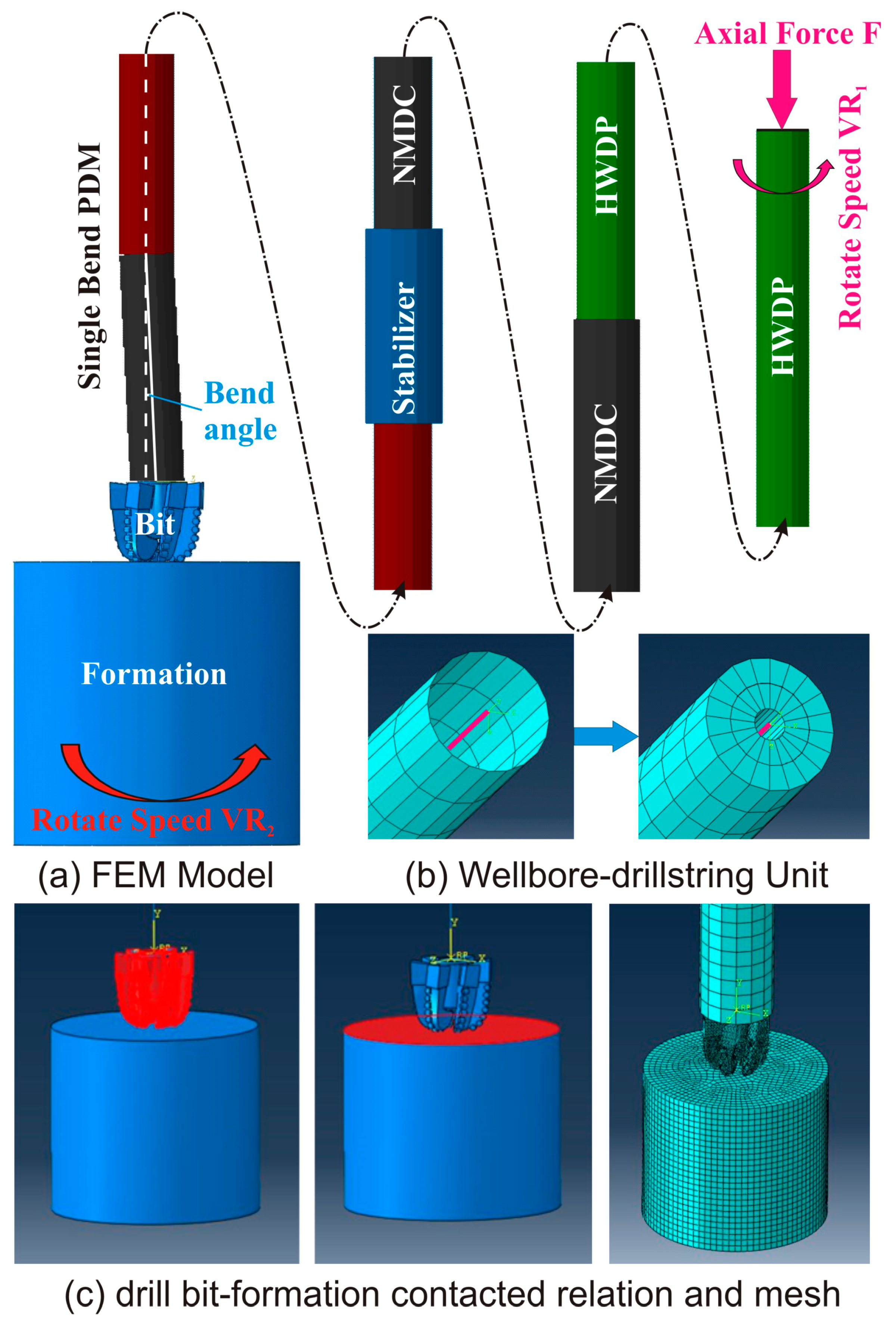
In order to establish the finite element of a bottom hole assembly with bent-housing PDM tool, the following BHA configuration was used: Ф215.9 mm PDC bit × 0.35 m + Ф172 mm bent-housing PDM tool (1.25°) × 8.00 m + Ф208 mm stabilizer × 1.00 m + Ф165 mm non-magnetic drill collar (NMDC) × 9.00 m + Φ139.7 mm heavy weight drill pipe (HWDP) × 60.00 m. The geometric parameters of this BHA are listed in Table 2.
In order to obtain the actual motion and force of the BHA, by involving the real formation, the full-sized PDC bit, and the full-sized wellbore, a 3D model was proposed by using ABAQUS software (Dassault Systèmes Simulia Corp., Waltham, MA, USA), as shown in Figure 1. The whole model is shown in Figure 1a. The top section shows a HWPD, followed by NMDC, stabilizer, and PDM tool and bit, and the bottom part is the formation. The PDM tool, stabilizer, drill collar, and drill pipe were simplified as a beam element (B31), and each section had different properties. Because the B31 element was a kind of Timoshenko, and the shear deformation of the beam was involved in this element, it was suitable for simulating the rotating slender drill-string. The top section of BHA was rotated by the upper drill-string with a rotate speed (VR1) to simulate the rotation of the rotary table. The formation was rotated with a rotate speed (VR2) to simulate the rotation of the rotor in PDM tool. In order to simulate the drill-string-wellbore coupling, the drill-string-wellbore unit was used, as shown in Figure 1b. Considering the B31 element has no thickness, in order to avoid the influence of the gap between the drill-string and borehole wall, the thickness of wellbore was thickened to eliminate its impact. In addition, because the ABAQUS software does not support the definition of internal contact, we defined the internal contact between the bit and formation by modifying the inp command flow of the model, as shown in Figure 1c.
There is an important aspect regarding the simplified processing of the bend angle of the PDM tool. In this paper, we used a restarting analysis method for the ABAQUS software. We also used the combination analysis method of Standard implicit and Explicit display. The processing can be summarized as follows: (1) Set up a Standard static analysis step, then define the contact relationship between the bit and wellbore wall, and calculate the prestressed state of the BHA caused by the bend angle. (2) Set up a new Job and propose an Explicit dynamic analysis step, then add the stress state file that was obtained in the first step in Load module, and submit to simulate.

2.3. Boundary Conditions

When the FEM was proposed, the next step was to apply the boundary conditions. First, establish the generalized contact relationship between the drill-string and wellbore, and define contact attributes, where the deviation angle of borehole is set as 30°. Then, set the viscous damping coefficient of the drilling mud, which is used to simulate the damping effect of the drilling mud on the drill-string, and the mud density is set as 1.2 g/cm3. Define internal contact relationship between the drill bit and formation. Apply an axial loading of 50 kN at the top section of the BHA to simulate the weight-on-bit (WOB), and apply a rotate speed VR1 = 60 rpm at the top section of BHA to simulate the rotation of the rotary table. Apply a rotation speed VR2 = 180 rpm on the formation to simulate the rotation of the rotor in PDM tool.
After applying boundary constraint and load conditions, we used the ABAQUS/EXPLICIT integral algorithm to solve the dynamic model of BHA-bit-formation-wellbore system. By solving Equation (9), we obtained the simulation results of dynamic model for the BHA-bit- formation-wellbore system.

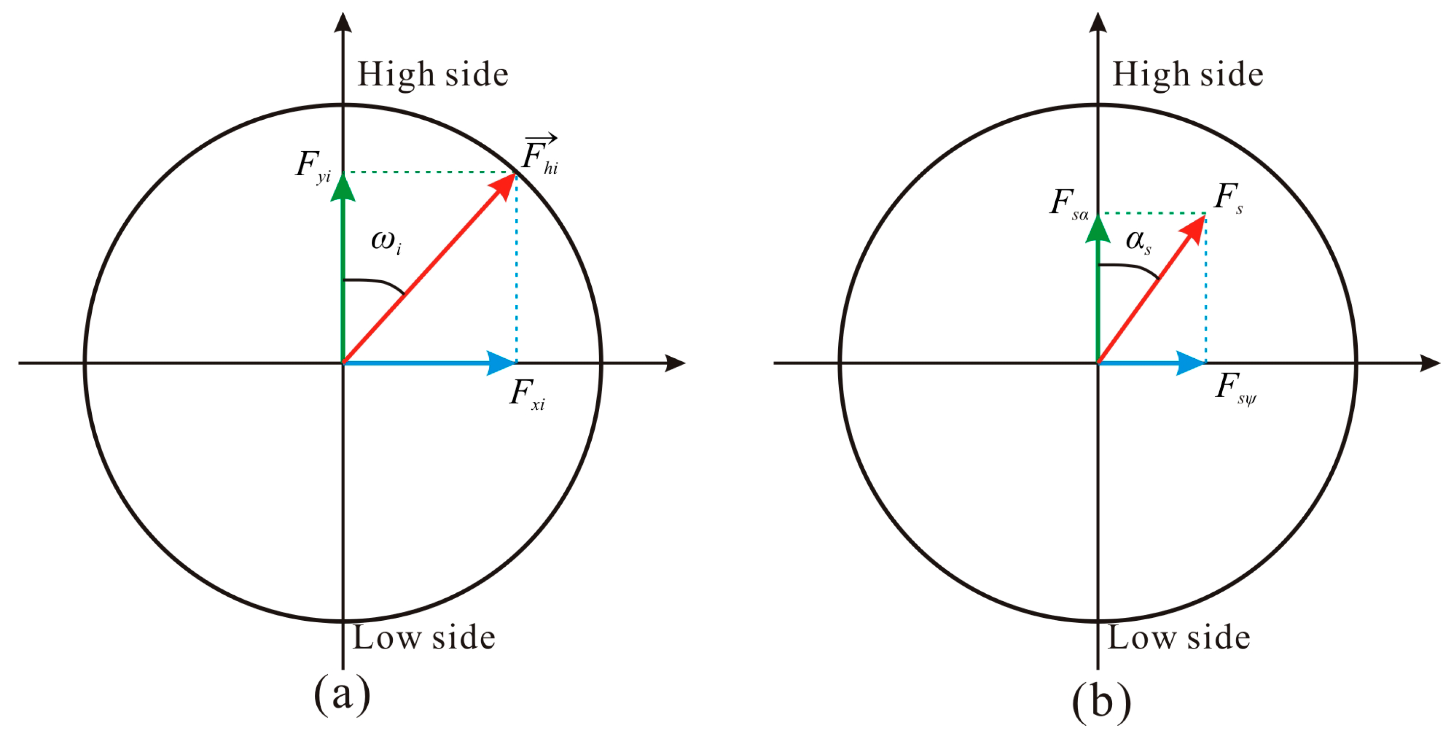
2.4. Extracting the Resultant Steering Force

According to the deviation angle and azimuth angle of the BHA, the position of the drill bit at the bottom can be determined. In this present model, the bit pointed to the low side of the borehole at the initial moment, and the low side (90°) is located at the 6:00 position of the wellbore or the bottom of the hole, whereas the high side (0°) is the 12:00 position of the wellbore or the top of the hole. In order to obtain the dynamic resultant steering force on bit in one round, we used a decomposition and synthesis of forces to calculate the steering force on the bit. As shown in Figure 2a, the side force on the bit is a vector F h i ; thus, the side force F h i can be decomposed into azimuth force F x i in the x direction and build-up force F y i in the y direction:
{ F x i = | F h i | sin ω i F y i = | F h i | cos ω i
where, F h i is the vector of side force on the bit, F x i is the azimuth force in the x direction, F y i is the build-up force in the y direction, ω i is the tool face angle, and i is the simulating step in one round, i = 1 – n, where n is the total number of simulating steps.
Then, the resultant build-up force and azimuth force can be expressed as [19]:
{ F s α = ω = 0 2 π F y i F s ϕ = ω = 0 2 π F x i
where F s α is the total build-up force in the y direction and F s ϕ is the total azimuth force in the x direction.
The build-up and drop-off force can be expressed as:
{ F s α + = 1 n ω = 0 2 π F y i F s α = 1 n ω = 0 2 π ( F y i )
where F s α + is the average build-up force and F s α is the average drop-off force.
Thus, as shown in Figure 2b, the resultant steering force in one round can be obtained [19]:
F s = 1 n F s α 2 + F s ϕ 2 = 1 n ( ω = 0 2 π F y i ) 2 + ( ω = 0 2 π F x i ) 2
where F s is the resultant steering force in one round.
As shown in Figure 2b, the direction angle of steering force can be expressed as [19]:
α s = arctan ( F s ϕ F s α ) = arctan ( ω = 0 2 π F x i ω = 0 2 π F y i )
where α s is the direction angle of the resultant steering force in one round.

3. Analysis of Transient Dynamic Characteristics for BHA

In order to reveal the mechanical behaviors of the BHA with bent-housing PDM, the traditional BHA with a multi-stabilizer configuration was also used for comparison. Conventional rotary drilling with a rotation speed in the rotary table of 60 rpm, fully rotary drilling with a rotation speed in the rotary table of 60 rpm, and a PDM revolving speed of 180 rpm were simulated.

3.1. Impact Force

3.1.1. Impact Force between Stabilizer and Wellbore

As shown in Figure 3, whether conventional rotary drilling or fully rotary drilling are used, due to the interval between the stabilizer and wellbore being small, the stabilizer always impacts the wellbore. There is a comparatively obvious difference between conventional rotary drilling and fully rotary drilling: the average impact force of conventional rotary drilling is lower than fully rotary drilling. The first impact of the drill-string stabilizer occurred at 0.14 s with an impact force of 5.50 kN for fully rotary drilling, whereas it occurred at 0.12 s with a lower impact force of 10.03 kN for conventional rotary drilling. At 0–0.5s, a “start-to-impact” process of the drill-string stabilizer occurs, and there is approximately stabilizer impact occurs six and five times for fully and conventional rotary drilling, respectively. According to the impact frequency, the stabilizer impact of fully rotary drilling is higher than that of conventional rotary drilling. Approximately 51 and 32 stabilizer impacts occur for fully and conventional rotary drilling, respectively, in the 0–5.0 s timeframe, and the difference between them is almost 1.6-fold. According to the impact force, the stabilizer impact of fully rotary drilling is much more powerful than conventional rotary drilling. The average impact force is approximately 35.23 kN for fully rotary drilling, whereas it is approximately 30.42 kN for conventional rotary drilling. In the 2.0–3.0 s time frame, the maximum impact force of the stabilizer is approximately 98.5 kN for fully rotary drilling, whereas it is approximately 46.77 kN for conventional drilling. It is possible that an instantaneous unstable phenomenon occurs for the drill-string; the unstable phenomenon may lead to drill-string failure.

3.1.2. Impact Force between Drill Pipe and Wellbore

As shown in Figure 4, the impact force and frequency of fully rotary drilling is higher than conventional rotary drilling. The impact between the drill-string and wellbore is approximately 56 times with a maximum force of 96.71 kN and average force of 22.90 kN for fully rotary drilling, whereas it is approximately 22 times with a maximum force of 57.75 kN and average force of 18.25 kN for conventional rotary drilling. When contact and impact between the drill-string and wellbore occurred, the greater the contact force, the greater the friction and the reverse torque. Therefore, due to the powerful impact of fully rotary drilling, the impact force and frequency are much higher than in conventional rotary drilling. As a result, the reverse friction and torque are therefore much higher, the inversion phenomenon is much more obvious, and the wear is also much worse.

3.2. Acceleration

3.2.1. Axial Acceleration

As shown in Figure 5, the axial acceleration of the drill-string is relatively small, and mostly changed from –2.0 g to 2.0 g. The number of peak axial accelerations of fully rotary drilling is obvious larger than conventional drilling. In the period of 0–0.4 s, the axial acceleration of fully rotary drilling has more obvious fluctuations compared to conventional drilling. Because the teeth of the drill bit under fully rotary drilling (VR1 = 60 rpm and VR2 = 180 rpm) can wedge into rock much easier than conventional drilling (VR1 = 60 rpm). Thus, when the downhole rock breaks, the axial impact has much higher frequency and amplitude.

3.2.2. Lateral Acceleration

As shown in Figure 6, the lateral acceleration of the string is relatively higher than the axial acceleration, due to the influence of the full rotation of the BHA with a bent-housing PDM tool, mostly changing from –10 g to 10 g. The number of peak lateral accelerations for fully rotary drilling is larger than conventional drilling. In the process of lateral vibration, due to the movement being restricted in a very narrow borehole space, it is inevitable that the drill-string will contact and impact the wellbore wall.
Because the contact time is very short, a rapid change in the velocity and direction of the drill-string occurs before and after the impact, resulting in a large lateral vibration of the drill-string. According to the above analysis, in the period of 2.4–3.1 s and 4.0–4.5 s, there are several violent impacts at or near the stabilizer between the drill-string and wellbore wall, leading to a very large lateral acceleration (~23.10 g). Similar situations occurred at 1.65 s, 3.4 s, and 4.8 s. Combined with Figure 4, it can be seen that there are some violent impacts between the drill-string and the borehole wall. We clearly found that the lateral acceleration of fully rotary drilling is obvious higher than conventional drilling, and the drill-string may experience transient instability. Thus, the severe lateral impact between the drill-string and borehole wall may cause MWD tool damage, and even cause drill-string failure.

3.3. Axial Loading

As shown in Figure 7, the axial loading presents a regular periodic change for both conventional and fully rotary drilling, because the drill bit does not continuously cut the rock, but rather is step-by-step cutting in “jumps”, which is called as the “drilling footage step” phenomenon. At each step of the drilling footage, the drill bit cut the downhole rock several circles, but did not break the downhole rock, so the WOB always changed around 50 kN. Only if the rock in the whole step of the drilling footage was broken would the drill bit can cut into another step. Completion of a cycle is considered when the drill bit cut into another step, due to the suddenly drop of the drill bit in a short interval, so that a huge fluctuation in axial loading in the drill-string occurred. Therefore, each step is a cycle of “drilling footage step”.
From the perspective of the frequency for this cycle, there were six and eight cycles for conventional and fully rotary drilling, respectively, i.e., the period of this cycle was approximately 0.167 s and 0.125 s for conventional and fully rotary drilling, respectively. This phenomenon reveals why the ROP of fully rotary drilling is higher than conventional drilling. In addition, the amplitude of dynamic axial loading under fully rotary drilling was obviously higher than conventional drilling, where the maximum axial loading under fully rotary drilling was approximately 298.4 kN (~six times WOB), whereas the maximum axial loading under conventional drilling was approximately 253.8 kN (~five times WOB). On the whole, due to the higher rotation speed of the drill bit in fully rotary drilling, the axial loading under fully rotary drilling was higher than conventional drilling. The drilling footage step cycle was larger and the ROP of the fully rotary drilling was also much higher. However, due to the stronger vibration of the drill-string during fully rotary drilling, instability and fatigue damage of the drill-string more easily occur.

3.4. Torque

As shown in Figure 8, the torque constantly changes and fluctuates during drilling. During the period of 0–0.5 s, due to the bit tooth gradually cutting into the rock, the torque on the bit increased gradually. Comparing fully rotary drilling to conventional drilling, the rate of increase in torque was higher due to its ROP is much higher, so that the bit tooth could cut into the rock more easily. When the bit tooth completely cut into the rock, the torque on the bit transitioned into a regular fluctuation. When the WOB applied to the drill bit was the same (50 kN), the torque under fully rotary drilling was higher than conventional drilling. Under fully rotary drilling, the torque varied from 0 kN·m to 39.63 kN·m, and its mean was approximately 15.16 kN·m. Under conventional drilling, the torque varied from 0 kN·m to 35.01 kN·m, and its mean was approximately 12.63 kN·m. The torque on the bit is a factor of rock properties, bit, WOB, and rotation speed. For fully rotary drilling, the rock properties, bit, and static WOB were the same, but the dynamic WOB and rotation speed were different, so that torque under fully rotary drilling was higher than conventional drilling, and the high torque mainly originated from the higher fluctuation in the WOB.

3.5. Equivalent Stress

Figure 9 shows the maximum equivalent stress versus time for both conventional and fully rotary drilling. On the whole, the dynamic equivalent stress of fully rotary drilling was much higher than that of conventional drilling. The stress concentration appeared at the top section of the drill-string at the beginning stage, due to the rotation of drill-string being unnecessary to overcome the collision and friction between the drill-string and wellbore. However, it was also necessary to overcome the anti-torque generated by the contact between the drill bit and the formation rock. With the increase in rotating time, the stress distribution on the whole BHA reached a new equilibrium state, and only some individual bending parts demonstrated the phenomenon of stress concentration. Comparing fully rotary drilling to conventional drilling, the stress concentration at the beginning stage was significant due to the higher rotation speed of the drill bit during fully rotary drilling. In fact, this phenomenon is a simple and easy understood in dynamics; the higher the start-up speed of the drill-string, the higher the loading induced by dynamic inertia, so that the dynamic equivalent stress was much higher. When the drill-string is completely rotated, the drill-string may be inflected, due to the integrated influence of WOB, autorotation, revolution, and impact. On the whole, the configuration of the drill-string in 3D space during fully rotary drilling looks much more complicated than conventional drilling, and the drill-string showed a relatively obvious sinusoidal bend. This was mainly caused by the strong lateral vibration induced by the fully rotation of both the drill-string and rotor of the PDM tool.

4. Verification of Dynamic Steering Force

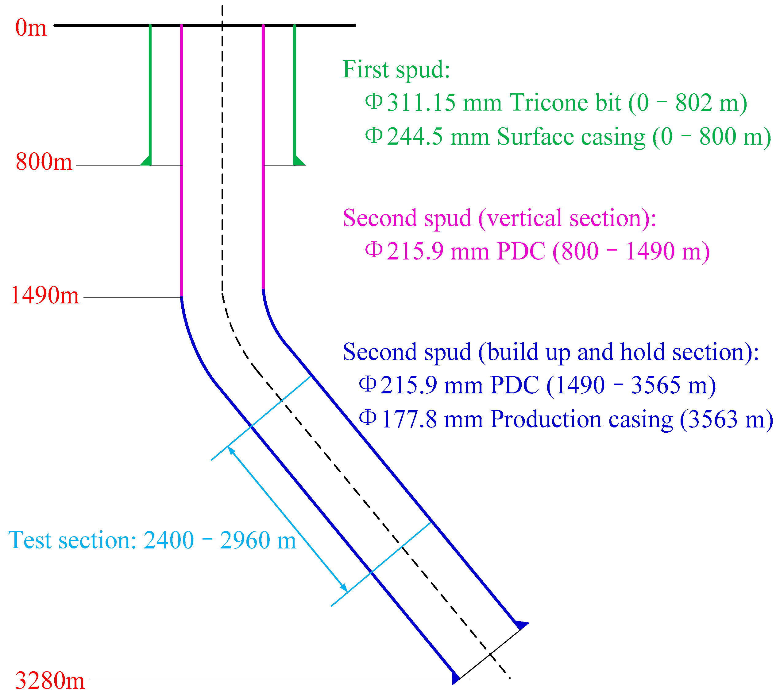
In order to verify the solution results of dynamic steering force, a directional well B located in the Sichuan basin in China was used to verify our model. The trajectory of well B is a kind of “straight-build-hold” type. The well had a kick off depth of 1490 m and a build-up rate of 3°/30 m. The designed target had a true vertical depth (TVD) of 3280 m, a final deviation of 25.95°, and an azimuth of 293.06°. After finishing the sliding drilling of the build-up section, fully rotary drilling, combining the BHA with a bent-housing PDM and MWD tool, was used to drill the hold-on section at the measured depth of 2400–2960 m. The configuration of drill-string and casing program were as follows. The casing program (Figure 10) was Φ311.15 mm Bit (0–802 m) × Φ244.5 mm casing (0–800 m) + Φ215.9 mm bit (802–3565 m) × Φ177.8 mm casing (0–3563 m). The configuration of drill-string was Ф215.9 mm PDC, Ф172 mm 1.25° PDM, Ф208 mm stabilizer, Ф165mm NMDC, and Φ139.7 mm HWPD. The drilling parameters were rotation speed of 60 rpm, WOB of 60–80 kN, and mud density of 1.20 g/cm3.
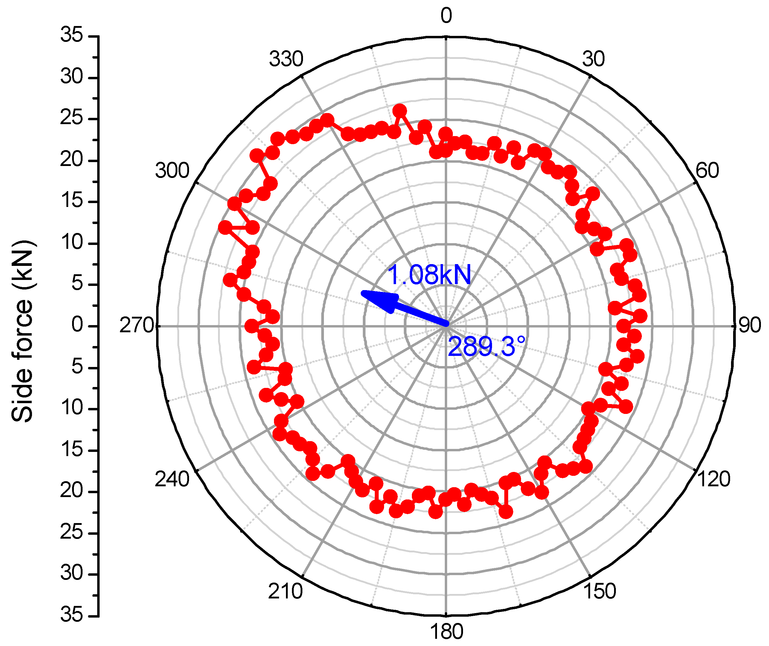
We conducted a numerical simulation for this well, and the side force acting on the drill bit in one round is shown in Figure 11. The side force along a given tool face angle was large, ranging from 20.01 to 30.73 kN, and the mean was approximately 23.08 kN. In other words, the steering force of sliding drilling was large for this well, and it is a typical build-up BHA. However, due to the rotation of the whole drill-string, the side force along a given tool face angle was not the resultant steering force.
By using the method mentioned above, the resultant steering force can be determined: Fs = 1.08 kN and αs = 289.3°. Although the steering force along a given tool face angle is large (20.01–30.73 kN), when the drill-string was rotated by the rotary table, the resultant steering force in one round was much less than the steering force along a given tool face angle (~1.08 kN). Thus, the rotation of drill-string is conducive for the hold-on deviation angle, and the present BHA showed mild build-up ability in deviation.
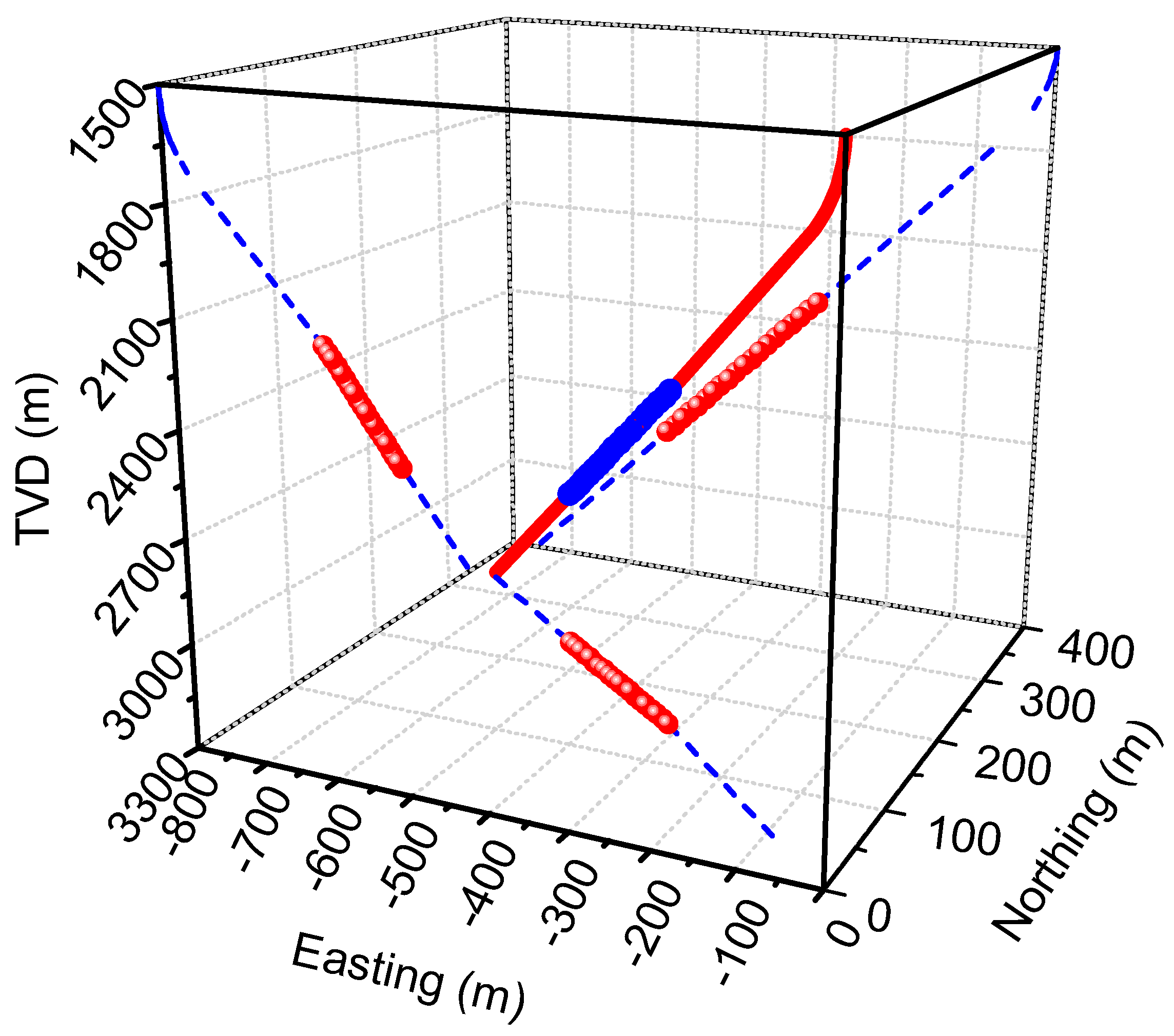
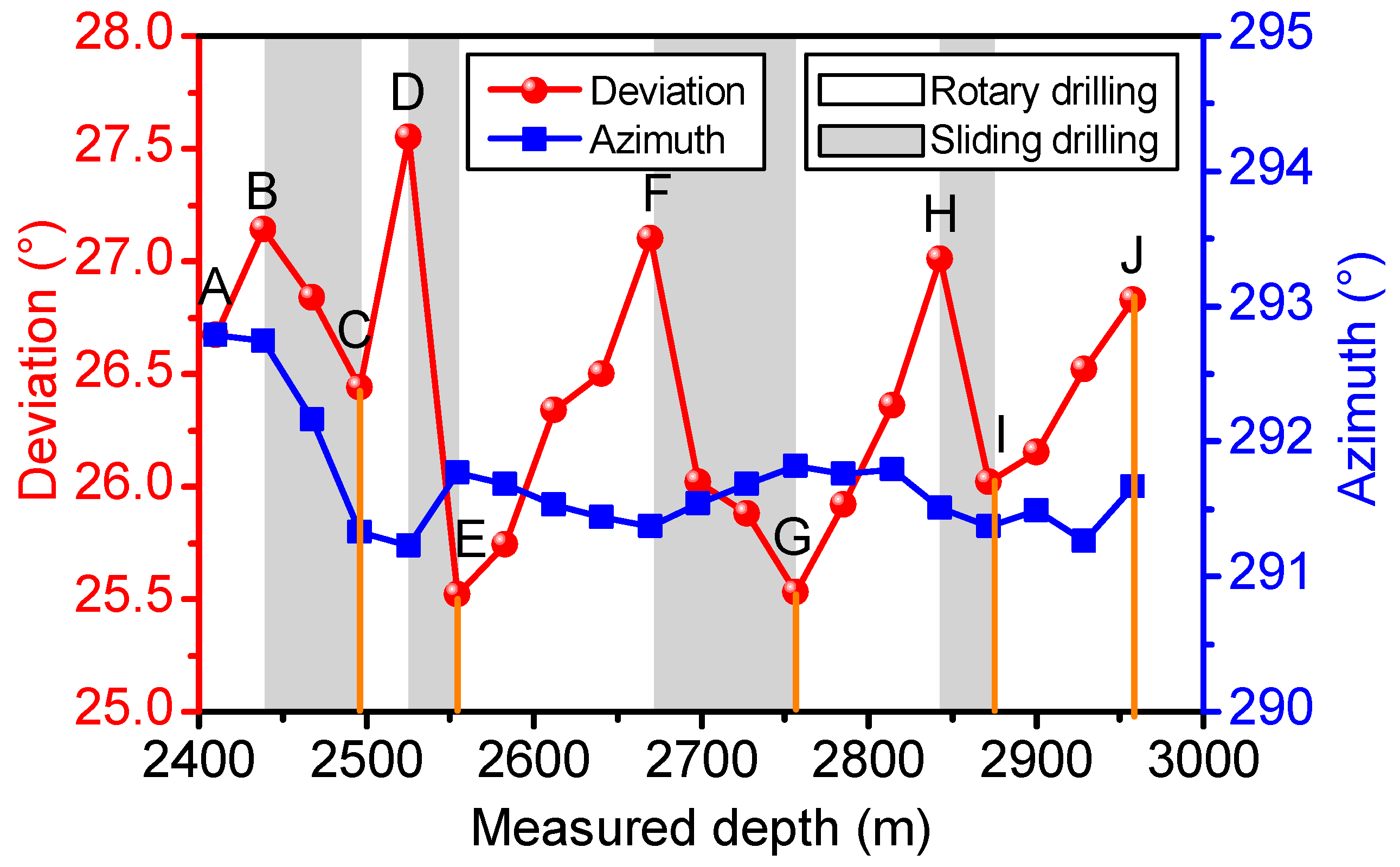
The trajectory of well B in the test interval is shown in Figure 12, and the trajectory data are listed in Table 3. We found that the overall angle in this hold-on section ranged from 0.041 to 0.707°/30 m, and the average of overall angle was approximately 0.195°/30 m. In fact, the present BHA presented slight build-up ability, as shown in Figure 13. There were five slight build-ups in the deviation during fully rotary drilling. In Figure 13, the well interval of 2409.87–2438.80 m (AB), 2496.59–2525.49 m (CD), 2554.40–2669.78 m (EF), 2756.39–2843.00 m (GH), and 2871.94–2957.70 m (IJ) were drilled using fully rotary drilling, whereas the other well intervals, 2438.80–2496.59 m (BC), 2525.49–2554.40 m (DE), 2669.78–2756.39 m (FG), and 2843.00~2871.94 m (HI), were drilled using sliding drilling to control the wellbore drop-off. As a result, the length of the well interval for sliding drilling was approximately 173.38 m, whereas the length of the well interval for fully rotary drilling was approximately 345.58 m. Thus, the ratio of sliding drilling in the test well interval reached 36.92%, whereas the ratio of fully rotary drilling was 63.08. The use of sliding drilling may lower the ROP, consume time and money, and easily forms “small steps” that affect the tortuosity of the wellbore, which overall decrease the borehole quality. Thus, these results obtained above were consistent with the numerical simulation results; in other words, the present model was verified.

5. Factors Influencing Dynamic Steering Ability

Many different factors can affect the dynamic steering ability of BHA with bent-housing PDM, such as the WOB, deviation angle, rotate speed, stabilizer position, stabilizer diameter, and bend angle. As most of these factors have been investigated, we only selected several factors to simulate the steering force of BHA for the test in well B to help us understand how to control the trajectory by adjusting these factors.

5.1. Influence of WOB

In general, the higher the WOB, the higher the ROP, but thane excessive WOB may cause the wellbore to deviate from the planned well path, creating a high risk for BHA buckling and failure. In order to determine the influence of WOB on steering ability, we conducted a numerical simulation. As shown in Figure 14, the resultant steering force on the bit should be the build-up force, and the resultant steering force increased with the increase in WOB. When the WOB was 50 kN, the resultant steering force was 1.767 kN, whereas when the WOB was 100 kN, the resultant steering force was 5.650 kN, which is approximately three times greater than the first value. Therefore, if fully rotary drilling is used to drill the hold-on section, the WOB should be optimized to ensure both ROP and the resultant steering force.

5.2. Influence of Deviation Angle

In general, the steering force is also affected by deviation angle. In order to investigate the influence of deviation angle on steering force, we conducted a numerical simulation with different deviation angles. As shown in Figure 15, the resultant steering force on the bit should be the build-up force. The resultant steering force firstly decreased and then increased with the increase in deviation angle. When the deviation angle was 0° (vertical well), the resultant steering force was 4.367 kN; when the deviation angle was 30° (deviated well), the resultant steering force reached the minimum value of 2.520 kN; when the deviation angle was 90° (horizontal well), the resultant steering force had the lowest value 6.856 kN, which is approximately three times that of the vertical well.

5.3. Influence of PDM Bend Angle

As shown in Figure 16, the resultant steering force on the bit should also be the build-up force. With the increase in bend angle of the PDM tool, the resultant steering force increased first, then decreased, and increased again. When the bend angle was 0.75°, the build-up force was 4.463 kN and the drop-off force was 3.595 kN. Consequently, the resultant steering force was 0.868 kN. When the bend angle was 1.50°, the build-up force was 16.702 kN and drop-off force was 10.53 kN. As such, the resultant steering force increased to 6.172 kN, which is approximately 7.11 times that of the former. Therefore, if fully rotary drilling is used to drill the hold-on section, the bend angle of the PDM tool should be selected properly. In general, the higher the bend angle, the higher the build-up force, which may cause the wellbore to deviate from the planned well path. If a proper bend angle of PDM tool is selected, it can be used to drill the hold-on section, and can also be used to correct the wellbore trajectory.

5.4. Influence of Stabilizer Location

The location of the stabilizer had a significant influence on the steering ability of BHA with bent-angle PDM. The appropriate stabilizer location can be used to adjust the steering ability. For fully rotary drilling, it can be used to hold-on the wellbore, to increase the ratio of rotary drilling, and to improve the ROP. For sliding drilling, it can be used to control the wellbore along the designed path to reach the target. Therefore, the location of stabilizer is a key factor that concerns engineers in the oil and gas field. As shown in Figure 17, the resultant steering force on the bit should also be the build-up force. With the increase in the distance between the stabilizer and drill bit, the resultant steering force increased. When the distance between the stabilizer and drill bit was 9 m, the build-up force was 11.983 kN and drop-off force was –9.734 kN. The resultant steering force was 2.249 kN. When the distance between the stabilizer and drill bit was 15 m, the build-up force reached 25.177 kN and the drop-off force reached –13.420 kN. Consequently, the resultant steering force increased to 11.758 kN, which is approximately 5.23 times that of the former. In other words, shortening the distance between the stabilizer and drill bit can decrease the resultant steering force, whereas lengthening the distance between the stabilizer and drill bit can increase the resultant steering force because the rigidity of drill-string is strengthened. Therefore, if fully rotary drilling is used to drill the hold-on section, the location of the stabilizer should be optimized.

5.5. Influence of Stabilizers’ Diameter

In addition to the location of the stabilizer, the outer diameter of the stabilizer can affect the steering ability of BHA. As shown in Figure 18, the resultant steering force on bit should also be the build-up force.
With the increase in the outer diameter of the stabilizer, the resultant steering force decreased. When the outer diameter of the stabilizer was 206 mm, the build-up force was 12.901 kN and drop-off force was –7.602 kN. Consequently, the resultant steering force was 5.300 kN. Conversely, when the outer diameter of the stabilizer was 212 mm, the build-up force was 10.660 kN and drop-off force was –8.701 kN; the resultant steering force was 1.959 kN, which is approximately 36.96% that of the former. In other words, increasing the outer diameter of the stabilizer decreases the resultant steering force. However, an excessively large outer diameter of the stabilizer could cause some complicated downhole complexities and accidents, and cause high friction of the drill-string due to the excessive rigidity of the drill-string. Therefore, if fully rotary drilling is used to drill the hold-on section, the outer diameter of the stabilizer should be selected properly.

6. Conclusions

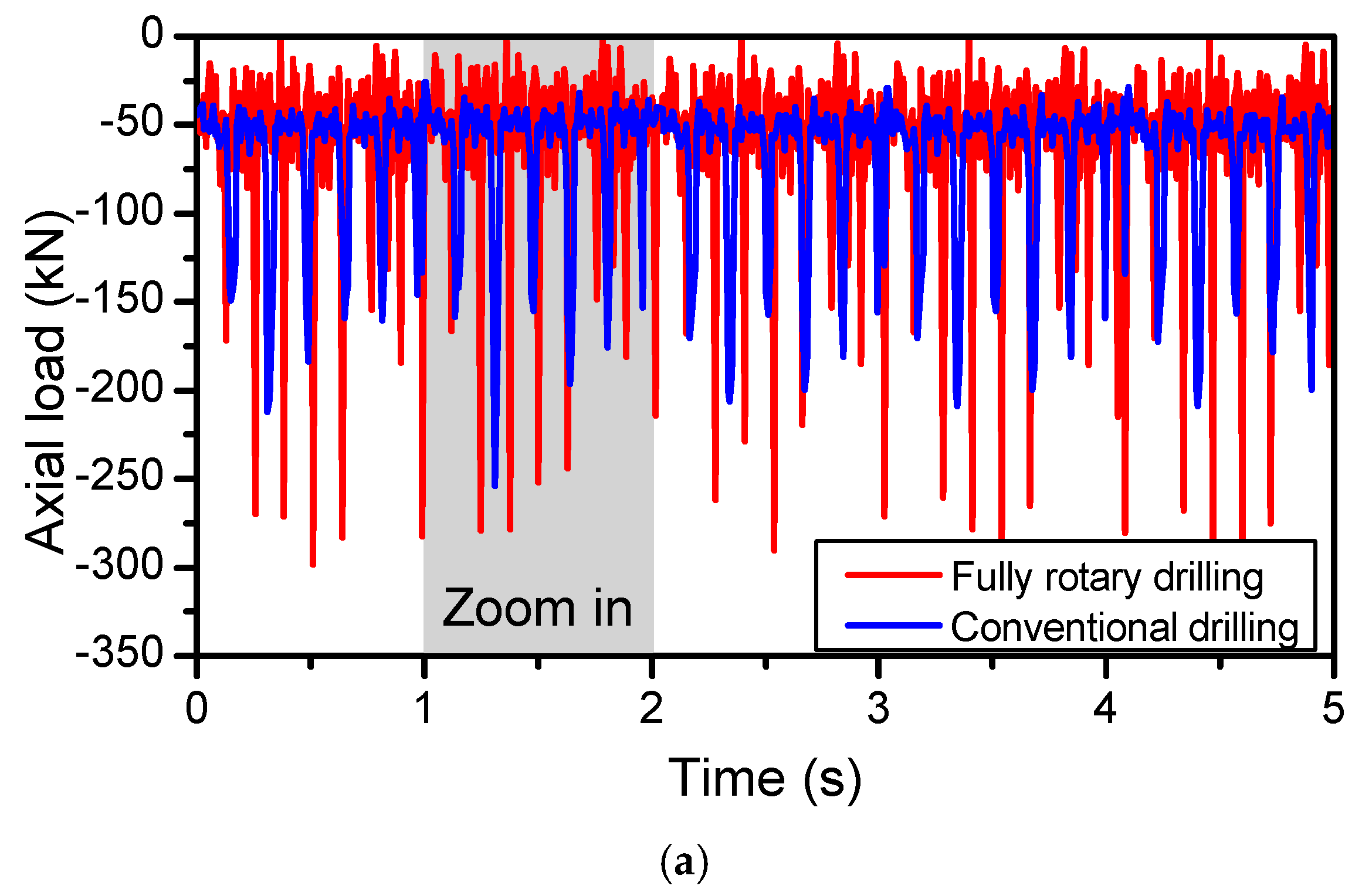
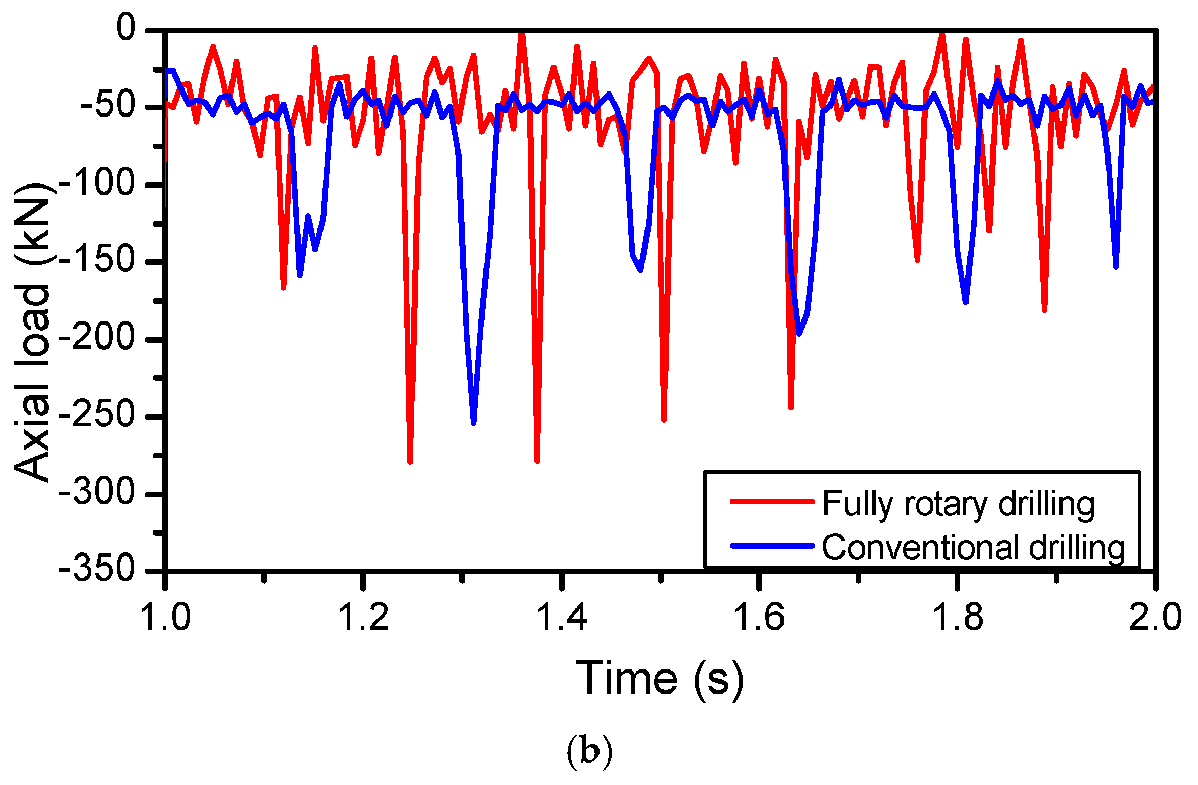
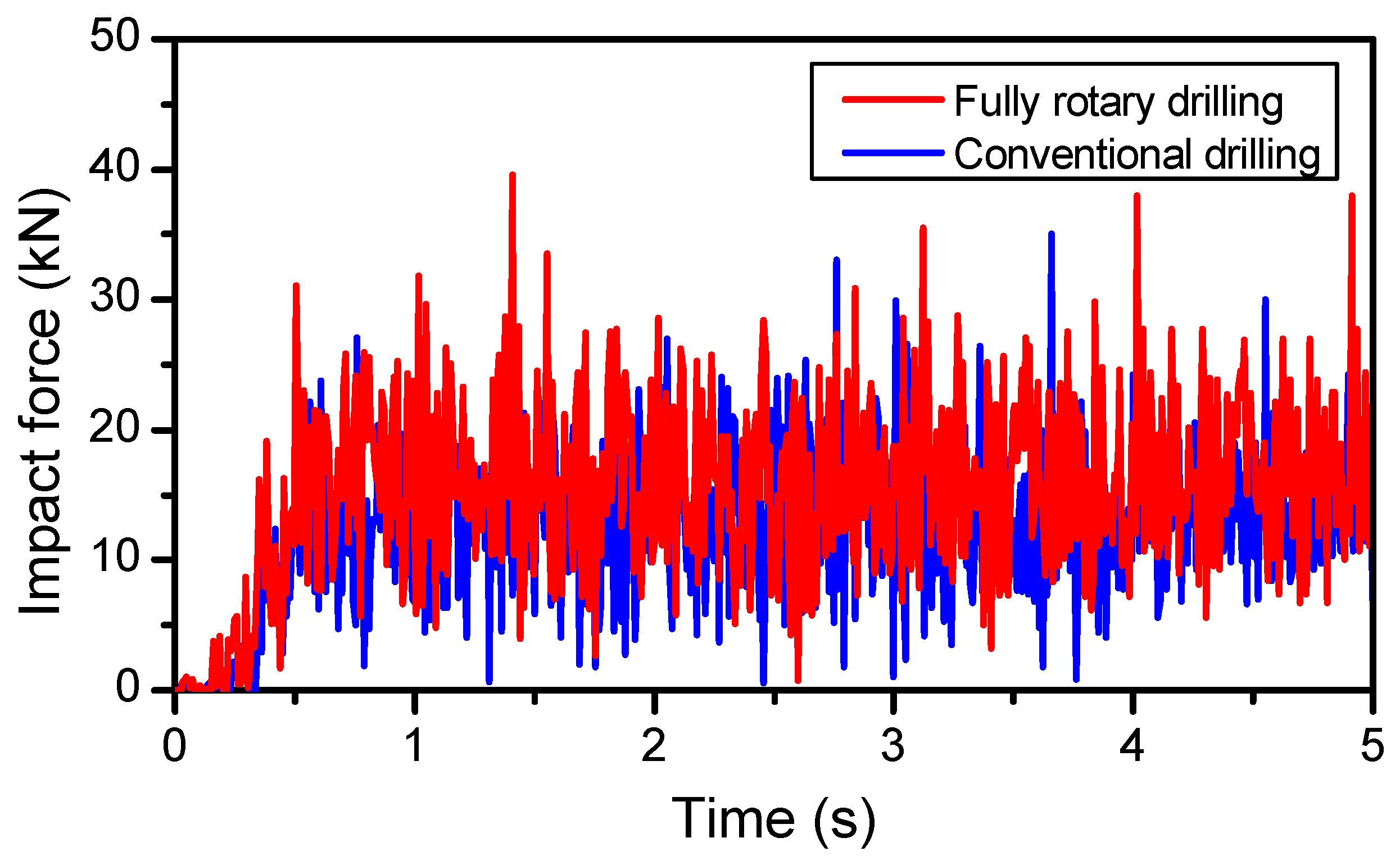
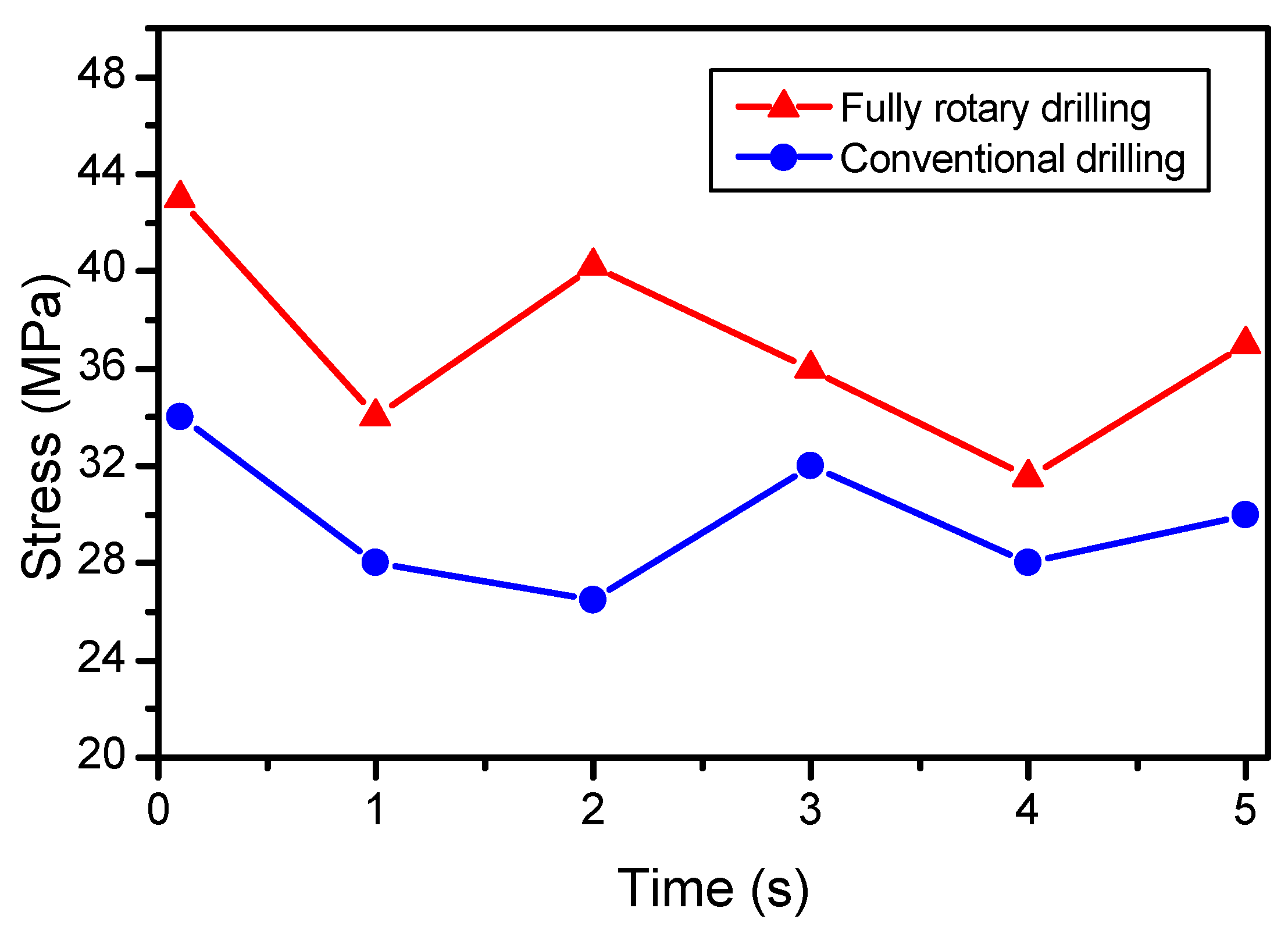
According to the Hamilton principle, a nonlinear coupled BHA-bit-formation-wellbore model was proposed for BHA with bent-housing PDM using the finite element method. The impact force, axial loading, torque, dynamic stress, axial acceleration, and lateral acceleration on BHA were simulated, and the factors influencing dynamic steering force were investigated. The following main conclusions can be drawn.
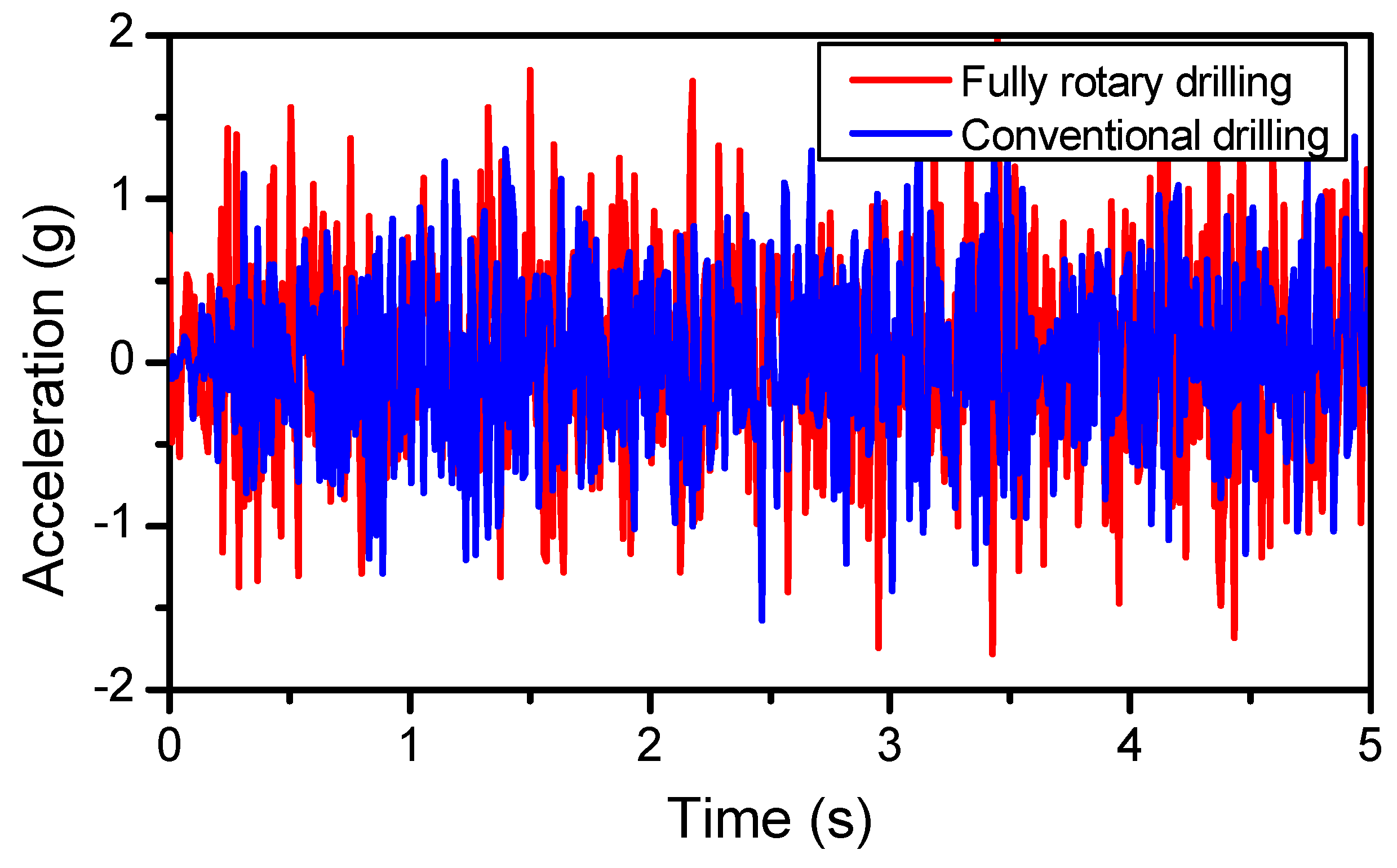
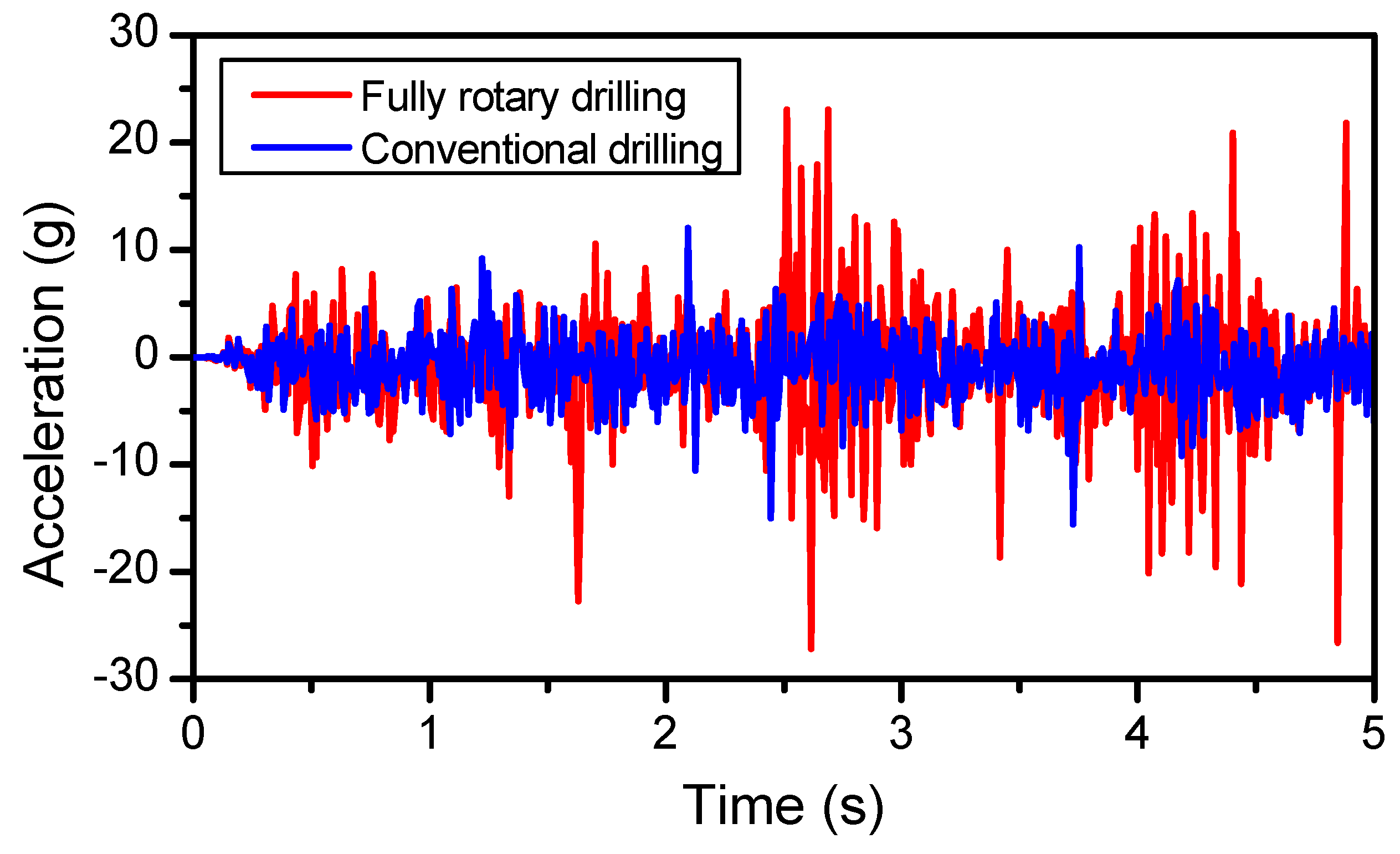
Firstly, for fully rotary drilling, the lateral acceleration is obviously greater than that of the axial acceleration, where lateral acceleration ranges from –10 g to 10 g, whereas the axial acceleration only ranges from –2 g to 2 g. The transient lateral acceleration can reach approximately 23.1 g. A severe lateral impact between the drill-string and borehole wall may cause the MWD tool damage, and even cause drill-string failure.
The FEM simulation and field test in well B confirmed that the rotation of the drill-string is conducive to the hold-on of the deviation angle, and the present BHA showed mild build-up ability in deviation. Although the steering force along a given tool face angle is considerable, when the drill-string was rotated by the rotary table, the resultant steering force in one round was not as large.
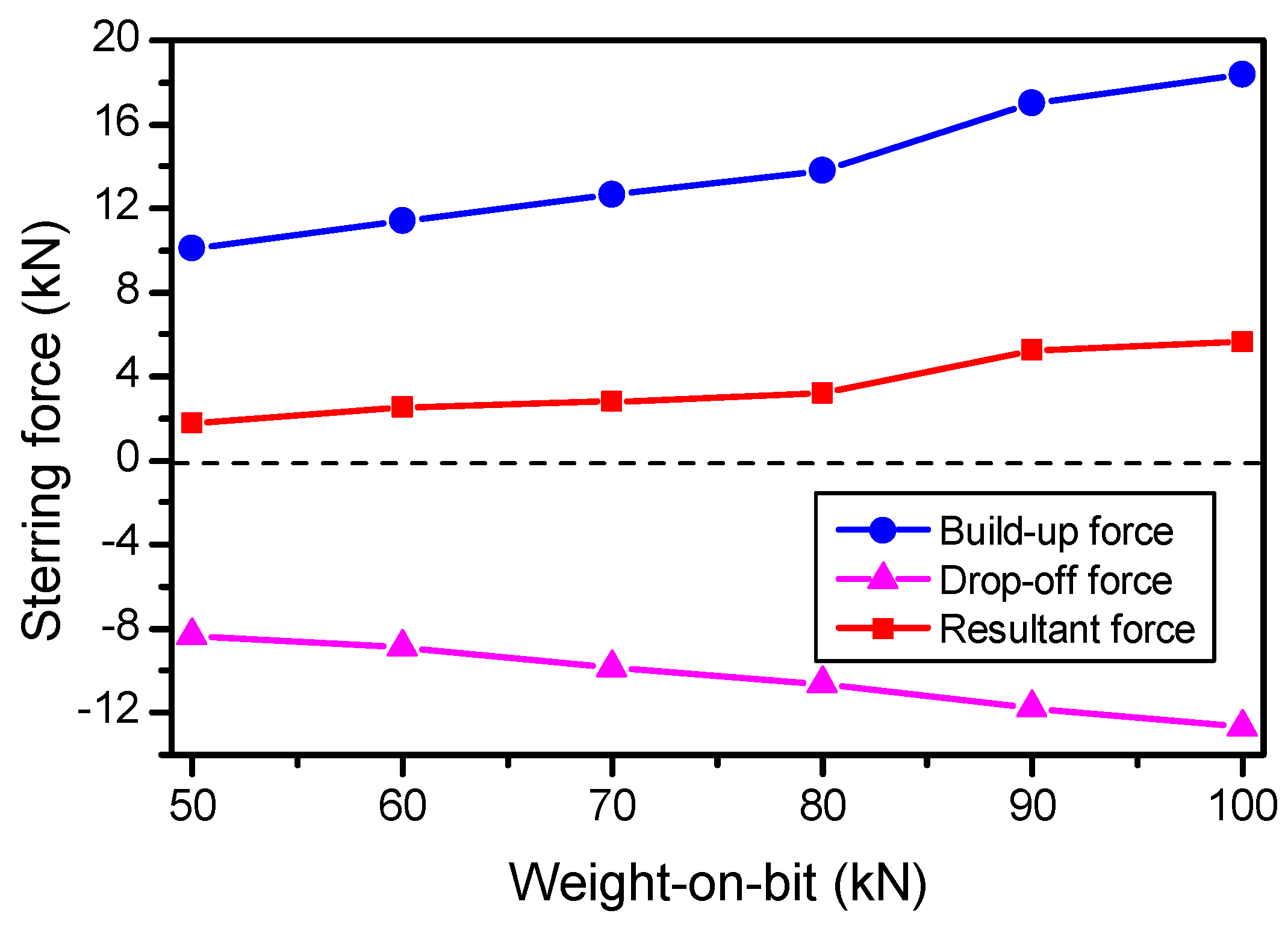
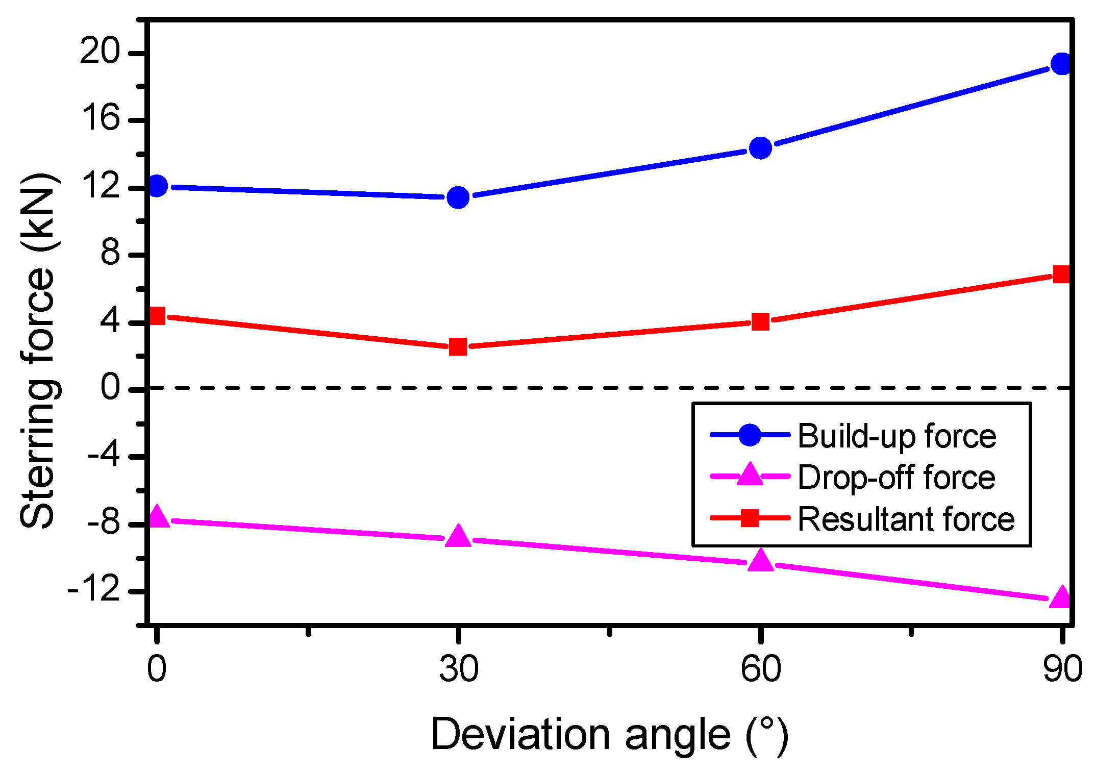
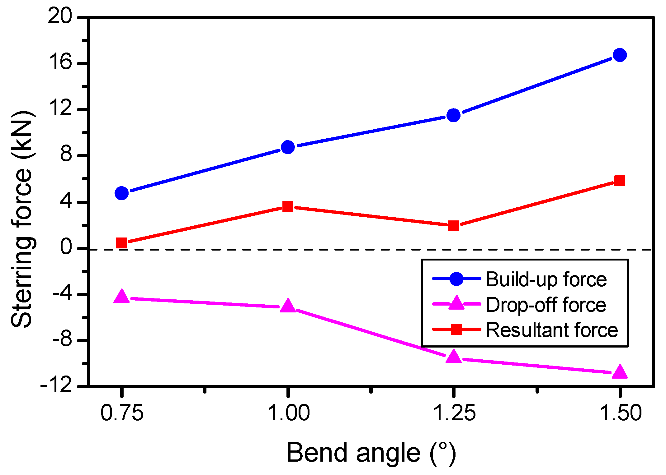
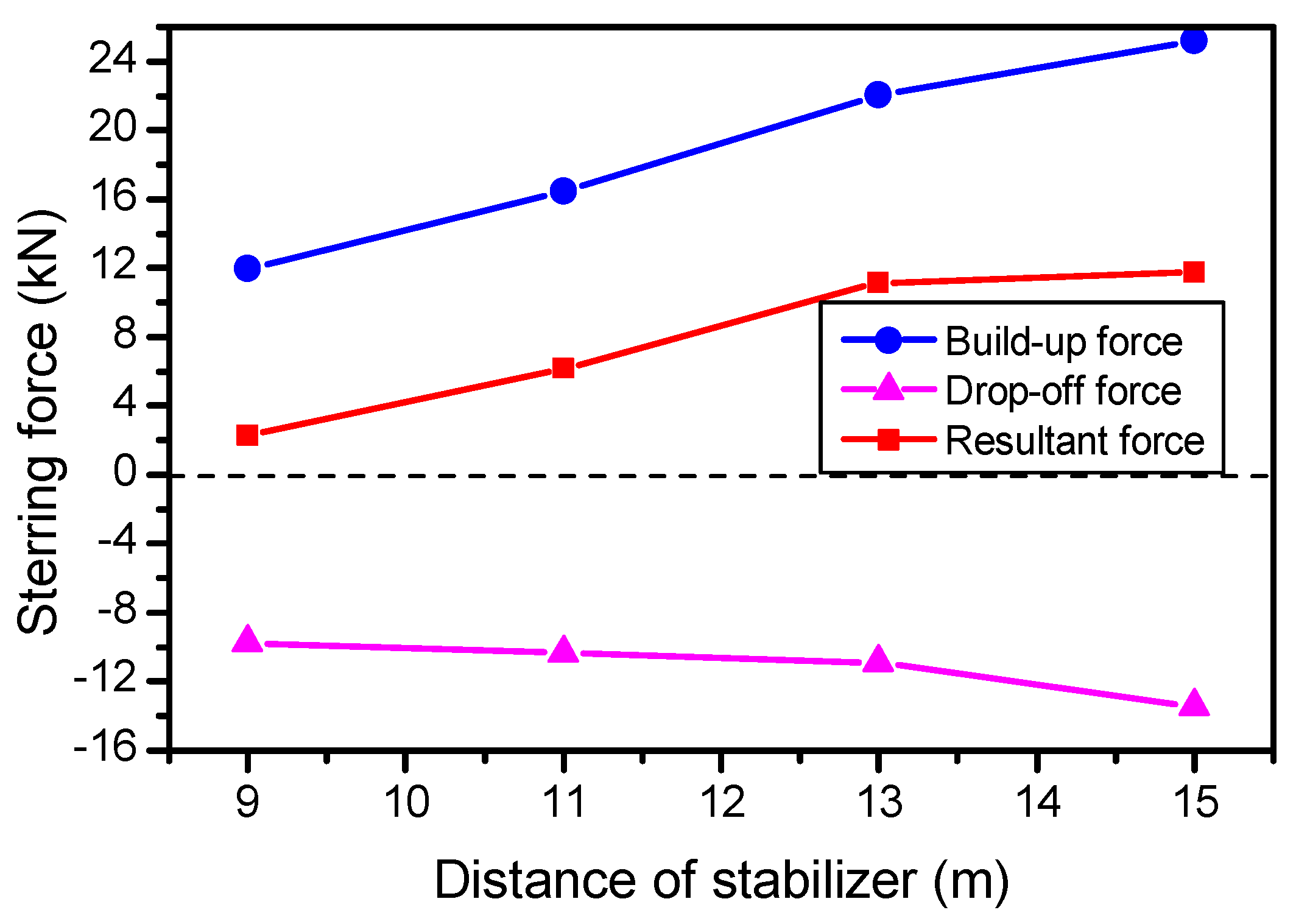
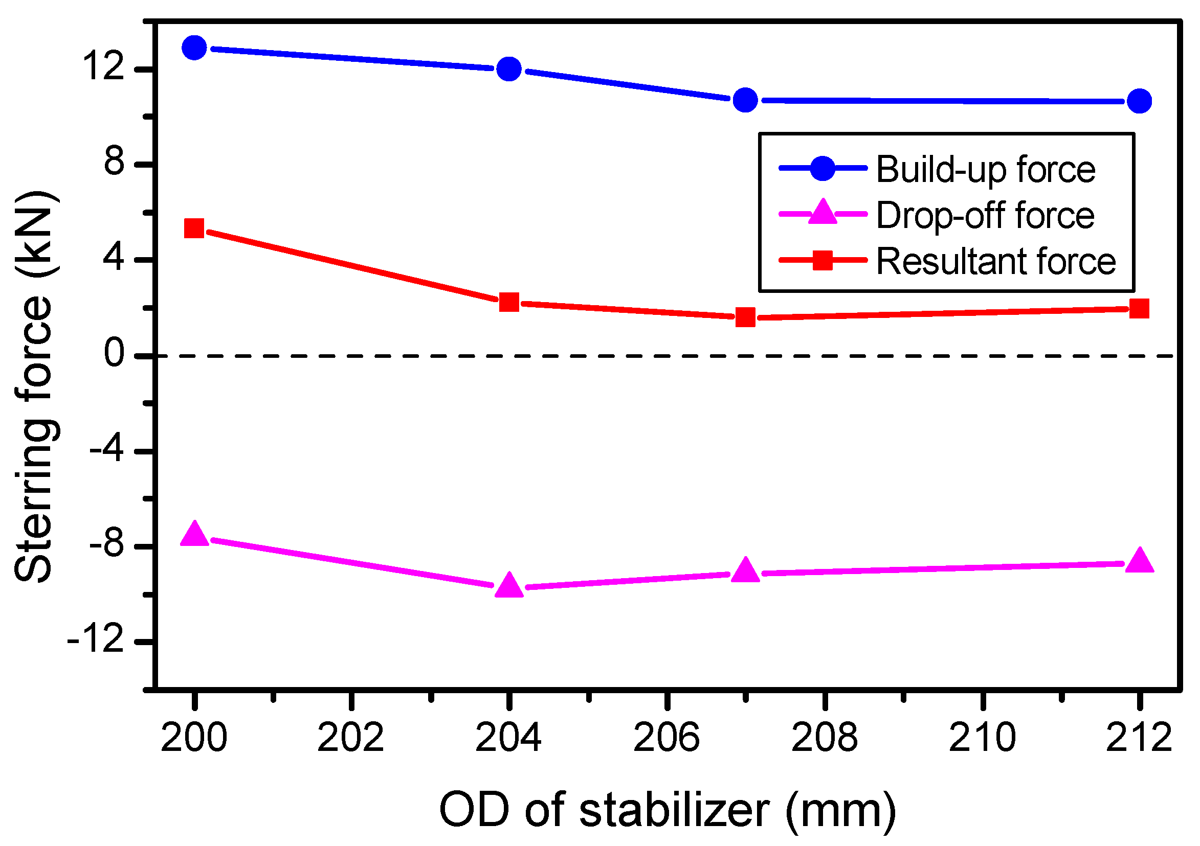
With the increase in the WOB and bend angle, and the higher stabilizer locations, the deflecting force on the drill bit increased, which is not conducive to the hold-on of the deviation angle. With the increase in stabilizer diameter, the deflecting force on drill bit decreased, which is conducive to the hold-on of the deviation angle. With the increase in the deviation angle, the deflecting force on the drill bit first decreased and then increased. Therefore, when designing the BHA, the configuration parameters of BHA and drilling parameters, such as bend angle, stabilizer location, stabilizer diameter, WOB, and rotation speed should be carefully considered to meet the requirements of oil and gas field drilling.

Author Contributions

Conceptualization, Y.C. and J.F.; Investigation, Y.C., T.M. and A.T.; Methodology, Y.C. and A.T.; Supervision, J.F.; Writing—original draft, Y.C., T.M. and A.T.; Writing—review & editing, J.F., Z.G. and X.W.

Acknowledgments

This work was supported by the National Science and Technology Major Project of China (Grant No. 2016ZX05022-01), the Scientific Research Foundation of International Cooperation and Exchanges of Sichuan Province (Grant No. 2017HH0061), the National Natural Science Foundation of China (Grant Nos. 41874216), the Program of Introducing Talents of Discipline to Chinese Universities (111 Plan) (Grant No. D18016), and the Young Elite Scientists Sponsorship Program by CAST (2017QNRC001).

Conflicts of Interest

The authors declare no conflict of interest.

References

  1. Liu, H.; Ma, T.; Chen, P.; Yang, C. Mechanical behaviors of bottom hole assembly with bent-housing positive displacement motor under rotary drilling. Arab. J. Sci. Eng. 2017. [Google Scholar] [CrossRef]
  2. Ma, T.; Chen, P.; Zhao, J. Overview on vertical and directional drilling technologies for the exploration and exploitation of deep petroleum resources. Geomech. Geophys. Geo-Energy Geo-Res. 2016, 2, 365–395. [Google Scholar] [CrossRef] [Green Version]
  3. Wu, A.; Hareland, G.; Lei, L.; Lin, Y.; Yang, Y. Modeling and prediction of cone rotary speed of roller cone bits. In Proceedings of the SPE Unconventional Resources Conference Canada, Calgary, Alberta, Canada, 5–7 November 2013. [Google Scholar]
  4. Feng, J.; Fu, J.; Wu, Z.; Liu, J. The application of high pressure jetting drilling in Eastern Sichuan. Int. J. Oil Gas Coal Technol. 2014, 7, 375–385. [Google Scholar] [CrossRef]
  5. Yin, H.; Si, M.; Wang, R.; Liu, H. A model based on orthogonal regression analysis for prediction of build rates in compound drilling in long horizontal section. Pak. J. Stat. 2014, 30, 1081–1092. [Google Scholar]
  6. Cui, M.; Li, J.; Ji, G.; Chen, Y. Optimize method of drilling parameter of compound drilling based on mechanical specific energy theory. Pet. Drill. Tech. 2014, 42, 66–70. [Google Scholar]
  7. Fu, J.; Li, G.; Shi, H.; Niu, J.; Huang, Z. A novel tool to improve the rate of penetration--hydraulic-pulsed cavitating-jet generator. SPE Drill. Complet. 2012, 27, 355–362. [Google Scholar] [CrossRef]
  8. Lubinski, A.; Woods, H.B. Factors affecting the angle of inclination and dog-legging in rotary bore holes. In Proceedings of the Drilling and Production Practice, New York, NY, USA, 1 January 1953. [Google Scholar]
  9. Miska, S. Developments in Petroleum Engineering (Volume I); Gulf Publishing Co.: Houston, TX, USA, 1987. [Google Scholar]
  10. Miska, S. Developments in Petroleum Engineering (Volume II); Gulf Publishing Co.: Houston, TX, USA, 1988. [Google Scholar]
  11. Bai, J.; Su, Y. Deviation Control Theory and Practice; Petroleum Industry Press: Beijing, China, 1990. [Google Scholar]
  12. Li, Z.; Zhang, C.; Song, G. Research advances and debates on tubular mechanics in oil and gas wells. J. Pet. Sci. Eng. 2017, 151, 194–212. [Google Scholar] [CrossRef]
  13. Dykstra, M.W. Nonlinear Drill String Dynamics. Ph.D. Thesis, The University of Tulsa, Tulsa, TX, USA, 1996. [Google Scholar]
  14. Liu, J.B.; Zhang, X.H.; Sun, C.; Zhong, Q.G. Bent beam unit analysis of drill stem deformation in horizontal well. Nat. Gas Ind. 1996, 17, 38–40. [Google Scholar]
  15. Di, Q.F. Calculation and analysis of the steering force of the compounding slide steering assembly. Oil Drill. Prod. Technol. 2000, 22, 14–16. [Google Scholar]
  16. Di, Q.F.; Yue, Y.H.; Peng, G.R. Calculating the steering force of the compounding slide steering assembly and its main influence parameters. Pet. Drill. Tech. 2001, 29, 56–57. [Google Scholar]
  17. Zhou, J.C.; Yu, X.Y.; Luo, Y.; Di, Q.F. The research and application of the coupled driven drilling technology. Ch. Offshore Oil Gas 2007, 19, 188–191. [Google Scholar]
  18. Di, Q.; Zhu, W.; Yao, J.; Zou, H. Dynamic model of bottom hole assembly used in pre-bending dynamic vertical and fast drilling technology. Acta Pet. Sin. 2007, 28, 118–121. [Google Scholar]
  19. Di, Q.F.; Wu, Y.L.; Shi, X.Q. Primary research on vertical and fast drilling technology with pre-bending dynamic method. Acta Pet. Sin. 2003, 24, 86–89. [Google Scholar]
  20. Hu, Y.B. Finite Element Analysis of Dynamic Characteristics of Drillstring Based on Actual Well Path. Ph.D. Thesis, Shanghai University, Shanghai, China, 2011. [Google Scholar]
  21. Hu, Y.; Di, Q.; Li, H.; Wang, W.; Yao, J. Dynamic characteristics analysis and parameter optimization of rotary steering bottom-hole assembly. Oil Drill. Prod. Technol. 2011, 33, 8–11. [Google Scholar]
  22. Cheng, Z.; Jiang, W.; Ren, G.; Zhou, J.; Jiang, S.; Yang, C.; He, B. A multibody dynamical model of full-hole drillstring system. Acta Pet. Sin. 2013, 34, 753–758. [Google Scholar]
  23. Yang, C.; Cheng, Z.; Jiang, W.; Jiang, S.; Ren, G. A multibody dynamic model of drillstring for torque and drag analysis. J. Offshore Mech. Arct. Eng. 2015, 137, 1–9. [Google Scholar]
  24. Wang, L.; Yang, J.; Butt, S.; Qiu, H. Investigation on effect of downhole vibration force on drilling performance with a dynamic BHA model. In Proceedings of the ASME 2015 34th International Conference on Ocean, Offshore and Arctic Engineering, Newfoundland, Canada, 31 May–5 June 2015. [Google Scholar]
  25. Lian, Z.; Zhang, Q.; Lin, T.; Wang, F. Experimental and numerical study of drill string dynamics in gas drilling of horizontal wells. J. Nat. Gas Sci. Eng. 2015, 27, 1412–1420. [Google Scholar] [CrossRef]
  26. Ghasemloonia, A.; Rideout, D.G.; Butt, S.D. Analysis of multi-mode nonlinear coupled axial-transverse drillstring vibration in vibration assisted rotary drilling. J. Pet. Sci. Eng. 2014, 116, 36–49. [Google Scholar] [CrossRef]
  27. Ghasemloonia, A.; Rideout, D.G.; Butt, S.D. A review of drillstring vibration modeling and suppression methods. J. Pet. Sci. Eng. 2015, 131, 150–164. [Google Scholar] [CrossRef]
  28. Zhu, X.; Jia, Y.; Tong, H. Static & dynamic characteristics of drill string during gas drilling. Chin. J. Appl. Mech. 2010, 27, 799–803. [Google Scholar]
  29. Zhu, X.H.; Li, B.; Liu, Q.Y.; Chang, X.J.; Li, L.C.; Zhu, K.L.; Xu, X.F. New analysis theory and method for drag and torque based on full-hole system dynamics in highly deviated well. Math. Probl. Eng. 2015. [Google Scholar] [CrossRef]
  30. Zhu, X.; Lai, C. Kinematics and mechanical properties analyses on vibration converter of intelligent damper for drill strings. Adv. Appl. Math. Mech. 2013, 5, 671–687. [Google Scholar] [CrossRef]
  31. Deily, F.H.; Dareing, D.W.; Paff, G.H.; Ortloff, J.E.; Lynn, R.D. Downhole measurements of drill string forces and motions. J. Manuf. Sci. Eng. 1968, 90, 217–225. [Google Scholar] [CrossRef]
  32. Millheim, K.; Jordan, S.; Ritter, C.J. Bottom-hole assembly analysis using the finite-element method. J. Pet. Technol. 1978, 30, 265–274. [Google Scholar] [CrossRef]
  33. Akgun, F. A finite element model for analyzing horizontal well BHA behavior. J. Pet. Sci. Eng. 2004, 42, 121–132. [Google Scholar] [CrossRef]
  34. Shi, C.; Zhu, X.; Luo, H. Study of DTH bit–rock interaction numerical simulation method and DTH bit properties evaluation. Arab. J. Sci. Eng. 2017, 42, 2179–2190. [Google Scholar] [CrossRef]
  35. Zhu, X.; Tang, L.; Yang, Q. A literature review of approaches for stick-slip vibration suppression in oilwell drillstring. Adv. Mech. Eng. 2014. [Google Scholar] [CrossRef]
Figure 1. Sketch map of finite element model (FEM) modeling for bottom hole assembly (BHA) under fully rotary drilling: (a) FEM, (b) element of wellbore-drill-string unit, and (c) drill bit-formation contact relationship and meshes.
Energies 11 02568 g001
Figure 2. Sketch map of decomposition and synthesis of the side force analysis on the bit: (a) Decomposition for the vector of side force on the bit and (b) synthesis of the resultant steering force on the bit.
Energies 11 02568 g002
Figure 3. Impact force versus time between stabilizer and wellbore for both fully rotary and conventional drilling.
Energies 11 02568 g003
Figure 4. Impact force versus time between drill pipe and wellbore for both fully rotary and conventional drilling.
Energies 11 02568 g004
Figure 5. Axial acceleration versus time on the BHA for both fully rotary and conventional drilling.
Energies 11 02568 g005
Figure 6. Lateral acceleration versus time on the BHA for both fully rotary and conventional drilling.
Energies 11 02568 g006
Figure 7. Axial loading versus time on drill-string for both fully rotary and conventional drilling: (a) axial loading versus time at 0–5 s and (b) axial loading versus time at 1.0–2.0 s.
Energies 11 02568 g007aEnergies 11 02568 g007b
Figure 8. Torque versus time on drill-string for both fully rotary and conventional drilling.
Energies 11 02568 g008
Figure 9. Maximum equivalent stress versus time for both conventional and fully rotary drilling.
Energies 11 02568 g009
Figure 10. The casing program of a directional well B.
Energies 11 02568 g010
Figure 11. Side force on bit distribution in one round for drilling in well B.
Energies 11 02568 g011
Figure 12. The trajectory of well B, where the blue points represent the survey data, the red points represent the subpoint of the survey data in three coordinate planes, the red full line represents the real drilling trajectory, and the blue dotted lines represent the subline of the real drilling trajectory in three coordinate planes.
Energies 11 02568 g012
Figure 13. Deviation and azimuth versus measured depth for the well interval of 2400–3000 m in well B.
Energies 11 02568 g013
Figure 14. Steering force versus weight-on-bit (WOB).
Energies 11 02568 g014
Figure 15. Steering force versus deviation angle.
Energies 11 02568 g015
Figure 16. Steering force versus the positive displacement motor (PDM) bend angle.
Energies 11 02568 g016
Figure 17. Steering force versus stabilizers’ location.
Energies 11 02568 g017
Figure 18. Steering force versus stabilizer diameter.
Energies 11 02568 g018
Table 1. Mechanical analysis methods of drill-string and their applicability. Modified from Li et al. [12].
No.Primary ClassificationSub-TypeCharacteristicsApplicability
Spatial DimensionalityDynamic or StaticDeflection Size
2D3DStaticDynamicSmall DeflectionLarge Deflection
1Differential equations method (DEM)Analytical solution
  • Fast calculation speed
  • Easy to use
  • Not suitable for complicated problems
×××
Beam-columnmethod
  • A simple semi-analytical method
  • Suitable for 2D problems
  • Not ideal for 3D problems
×××
Finite difference method
  • A good numerical method
  • Suitable for small and large deflection problems
  • Accuracy greatly depends on difference grid, resulting in a larger operational matrix and a slower operational speed
×
Weighted residual method
  • A powerful numerical method
  • Simple, accurate, and a knowable residual
  • Suitable for small and large deflection problems
  • Accuracy depends on the trial function
2Finite element method (FEM)/
  • A very good numerical analysis method
  • Suitable for solving mechanical problems with irregular areas and complex constraints
  • Suitable for static and dynamic analysis
  • Accuracy depends on the size of the unit, resulting in a larger computation task and a slower operational speed
3Energy method/
  • Suitable for solving 2D small deformation static problems
  • Not convenient for dealing with BHA and borehole wall contact problems
×××
Table 2. Geometric parameters of the bottom hole assembly (BHA) model.
No.Element of BHALength (m)OD (m)ID (m)
1Drill bit0.400.2159-
2Bent-housing PDM9.000.1720-
3Stabilizer1.300.20800.0714
4Non-magnetic drill collar (NMDC)9.000.16500.0714
5Heavy weight drill pipe (HWDP)100.000.13970.0920
Note: OD means outer diameter, and ID means inner diameter.
Table 3. The trajectory of test interval in well B.
No.Measured Depth (m)Inclination (°)Azimuth (°)TVD (m)N–S (m)E–W (m)Overall Angle (°/30 m)
12409.8726.67292.792331.97151.38–314.870.041
22438.8027.14292.742357.77156.45–326.940.163
32467.7226.84292.162383.54161.46–339.070.138
42496.5926.44291.332409.34166.26–351.090.189
52525.4927.55291.232435.09171.02–363.310.384
62554.4025.52291.772460.96175.75–375.330.707
72583.3525.74291.682487.06180.38–386.960.077
82612.3726.34291.532513.13185.08–398.810.208
92640.9226.50291.442538.70189.73–410.630.058
102669.7827.10291.372564.46194.48–422.740.208
112698.6326.02291.542590.26199.19–434.750.375
122727.6625.88291.682616.37203.87–446.560.053
132756.3925.53291.822642.25208.49–458.130.124
142785.3325.92291.762668.33213.15–469.800.135
152814.1126.36291.792694.16217.86–481.570.153
162843.0027.01291.512719.97222.64–493.630.229
172871.9426.02291.372745.87227.37–505.660.343
182900.2826.15291.492771.32231.92–517.260.050
192928.8526.52291.262796.93236.54–529.060.134
202957.7026.83291.672822.71241.28–541.110.125
Avg.-26.40291.70---0.195
Note: TVD means true vertical depth, N–S means north–south, E–W means east–west.

