1. Introduction
Due to increasing concerns on energy efficiency and environmental protection, the development of hybrid electric vehicles (HEVs) has been accelerating [
1,
2,
3,
4]. As the major components of HEVs, the electric motors have to achieve high efficiency, high power density, high torque density, high controllability, wide-speed range and maintenance-free operation [
5,
6,
7]. Since the permanent-magnet (PM) motor can fulfill most of the goals, this motor type has become the mainstream in the past years [
8,
9].
Generally speaking, the PM motors can be roughly categorized into two main classes, namely stator-PM motor and rotor-PM motor. The stator-PM motors, including doubly-salient PM (DSPM) motor [
10], flux-reversal PM (FRPM) motor [
11] and flux-switching PM (FSPM) motor [
12], enjoy robust rotor structure that is favorable for high-speed application. However, its torque density is relatively insufficient for high-end HEV application. On the other hand, as a representative candidate of rotor-PM motor, interior PM (IPM) motors that can provide excellent torque density have been one of the famous HEV candidates [
13]. Recently, as another prominent rotor-PM candidate, Vernier permanent-magnet (VPM) motor that utilizes magnetic gearing effect to boost up its torque density has begun to gain many attentions [
14].
The first VPM motor was probably proposed in 1995 [
15], followed by many research works on new topology developments. In general, these topologies can be roughly classified into three major groups, namely radial-flux type [
16], axial-flux type [
17] and linear flux type [
18]. Below these three major groups, various stator topologies, including open-slot type [
19], split-tooth type [
20] and hybrid-tooth type [
21]; and various rotor topologies, including surface-mounted type [
22], spoke-array type [
23] and halbach type [
24], can be further categorized.
The VPM motor typically employs the inner-rotor (IR) topology, while its armature windings are installed based on overlapping-winding arrangement [
25]. This conventional design suffers from two major demerits, namely long end-winding length and wastage of inner motor space. To improve the situation, the outer-rotor VPM (OR-VPM) motor that employs toroidal-winding arrangement has been proposed [
26]. Upon installation of the toroidal-winding arrangement, easier manufacturing process, higher fill winding factor and shorter end-winding length can be potentially achieved. However, similar as the conventional IR-VPM design, the OR-VPM motor still suffers from severe PM flux leakage and poor mechanical integrity. To get of the problem, the VPM motor with consequent-pole structure, which can improve its cost-effectiveness and robustness, is developed.
This paper aims to compare the VPM motors with the famous IPM motor that used in HEV application. The key motor specifications and experimental results of the profound IPM motor can be found in literature [
27] and this particular motor will be utilized as a benchmark motor for reference. Three VPM motors, namely the IR-VPM motor, the OR-VPM motor and the OR consequent-pole VPM (OR-CP-VPM) motor will be developed and optimized for comparisons. Their key motor performance will be analyzed and evaluated based on the criteria for modern HEV applications. The rest of this paper is organized as follows: The topologies and operating principles of the proposed VPM motors will be covered in
Section 2 and
Section 3, respectively. The key analysis approach, namely electromagnetic field analysis will be described in
Section 4, followed by optimization processes in
Section 5. The major motor performances will be included in
Section 6, while a more comprehensive evaluation will be given in
Section 7. Finally, a conclusion will be drawn in
Section 8.
2. Proposed Vernier Permanent-Magnet Motors
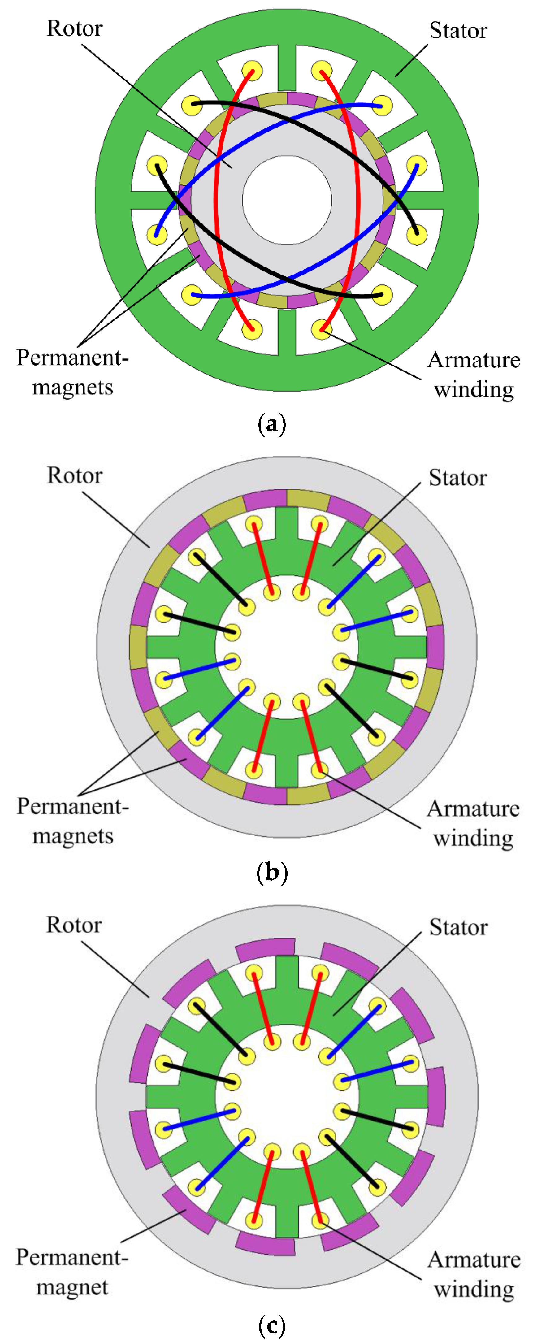
The IR-VPM motor, the OR-VPM motor and the OR-CP-VPM motor are shown in
Figure 1. All the motors share similar structure, i.e., one rotor, one stator, three-phase armature windings and 2/22-pole (two-stator-pole/twenty-two-rotor-pole) topology. Unlike the IR-VPM motor that employs the inner-rotor outer-stator topology, the OR-VPM and OR-CP-VPM motors instead employ the outer-rotor inner-stator topology.
The conventional IR-VPM motor consists of inner-rotor with alternating PM pieces installed on it, while the OR-VPM motor employs the same PM arrangements on its outer-rotor. Compared with its profound ancestors, the OR-CP-VPM motor instead equips its PM pieces with same polarity on its ferromagnetic pole shoes. Consequently, these ferromagnetic pole shoes can serve as poles with opposite polarity.
As mentioned, the traditional IR-VPM motor installs the armature winding based on the overlapping-winding arrangement, such that it suffers from relatively more complicated manufacturing process, lower fill winding factor and longer end-winding length. On the other hand, the OR-VPM and OR-CP-VPM motors can artfully utilize its inner motor spaces for winding accommodations. Consequently, both the OR-VPM and OR-CP-VPM motors can employ the toroidal-winding arrangement to improve the motor performances. In particular, easier manufacturing processes, higher fill winding factors and shorter end-winding lengths can be achieved. Moreover, lower copper losses and higher efficiencies can be resulted.
All the proposed motors, namely the IR-VPM motor, the OR-VPM motor and the OR-CP-VPM motor are designed based on the criteria of general HEV applications [
28]. To offer a fair comparison, all the key motor dimensions, namely outside diameters, stack lengths and airgap lengths are set equal.
3. Operating Principles
3.1. Magnetic Gearing Effect
Since the IR-VPM motor, the OR-VPM motor and the OR-CP-VPM motor are derived from the conventional VPM motor, their fundamental design equations can be extended from their ancestor as:
where
Pr is the number of rotor PM pole-pairs,
Ps is the number of stator pole-pairs and
Z is the number of stator slots.
All the VPM motors comply with the same operating principle, so-called as the magnetic gearing effect. In particular, a small movement of low-speed PM pole-pairs can generate a large flux variation to interact with high-speed rotating armature field [
14]. Consequently, the VPM motors behave as an integration of a PM motor and a magnetic gearbox, with operating speed
n as governed by:
where
f is the operating frequency.
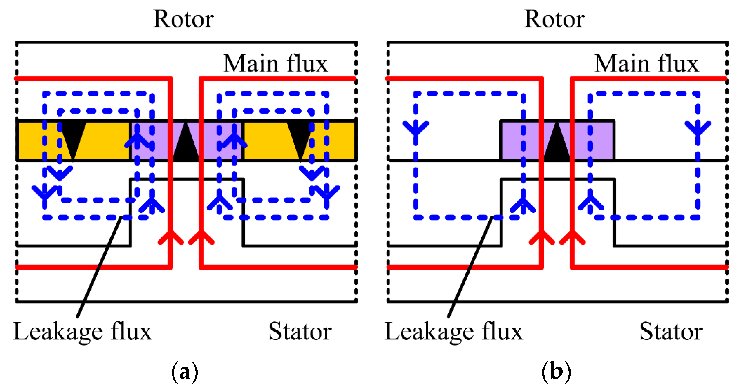
Upon the traditional PM arrangements, the IR-VPM and OR-VPM motors both suffer from ineffective utilization of PM materials. By taking the OR-VPM motor as an example in
Figure 2a, only part of its PMs can produce useful fluxes while the other PMs can only generate leakage fluxes. To be specific, only some fluxes excited by N-pole PMs can go through the airgap towards the stator slots, while some of the other fluxes are short-circuited with S-pole PMs as leakages. On the other hand, as shown in
Figure 2b, the OR-CP-VPM motor that employs the consequent-pole arrangement can reduce its leakage fluxes as compared with its counterparts. As a result, the OR-CP-VPM motor can produce relatively more main fluxes based on the reduced PM consumptions.
3.2. Torque Production
For the situation when reluctance torque is negligible, the electromagnetic torque of a typical three-phase PM motor can be expressed as [
25]:
where
e(
t) and
i(
t) are the phase back electromotive force (EMF) and current, respectively. It is obvious that the produced torque is highly influenced by its back-EMF waveforms, regarding both its magnitudes and patterns. Meanwhile, the phase back-EMF of the PM motors can be described as:
where
B(
θ) is the airgap flux density distribution,
L is the stack length,
N(
θ) is the phase winding function and
rg is the airgap radius. It can be seen that the back-EMF waveforms can be adjusted based on the optimization of motor parameters. As a result, it can be expected the produced torque can also be optimized accordingly.
Since the VPM motors are developed based on the similar mechanism from the conventional PM motor, these motors can be operated based on the profound bipolar conduction operations [
7]. In particular, a sinusoidal armature current
I should be injected with respect to the back-EMF waveforms
e. Consequently, a positive electromagnetic torque
T can be produced. This bipolar conduction operation is known as brushless ac (BLAC) operation, as shown in
Figure 3. The armature currents for BLAC operation are governed as:
In general cases, the back-EMF waveforms of the VPM motors consist of highly sinusoidal-like pattern, and hence it can be expected the produced torques should be very smooth. To quantitatively analyze the torque ripple performance, the torque ripple factor is defined as:
where
Tavg,
Tmax, and
Tmin are the average torque, maximum torque and minimum torque of the proposed motors, respectively.
4. Electromagnetic Field Analysis
When it comes to electric motor analysis, the electromagnetic field analysis must be one of the most convenient and accurate tools available in domestic market [
7]. In this paper, a popular commercial finite element method (FEM) software, JMAG-Designer (JMAG-Designer 17.0, JSOL Corporation, Tokyo, Japan) is employed for the motor performance analysis.
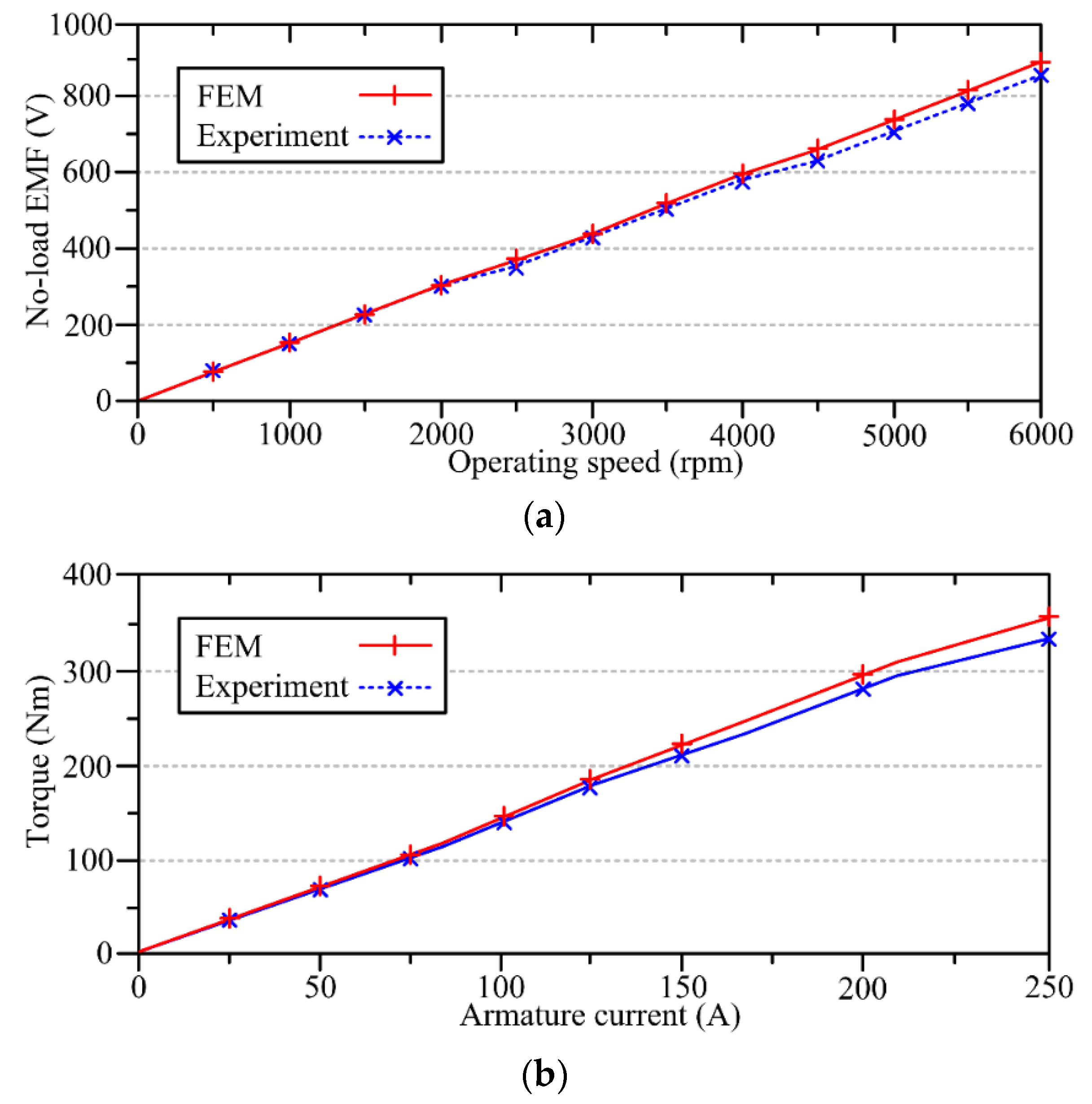
To verify the reliability of electromagnetic field analysis, the FEM results of the benchmark IPM motor are purposely compared with the experimental ones [
13]. In particular, its back-EMFs under various operating speeds and the locked torques under various armature currents are shown in
Figure 4. It can be shown that good agreements between the FEM and the experimental results are suggested. In particular, the maximum errors of the EMFs and torques between the FEM and the experimental results are less than 3.1% and 4.2%, respectively. Therefore, it can be confirmed the results generated from the electromagnetic field analysis are very reliable.
The magnetic field distributions of the proposed VPM motors at no-load conditions are shown in
Figure 5. It can be shown that the magnetic field distributions of the proposed VPM motors are very balanced. It should be noted that the leakages fluxes in the IR-VPM and the OR-VPM motors are more severe than those in the OR-CP-VPM motor. These results comply with the discussion in
Section 3.1.
5. Optimization of Motor Parameters
The optimization approach employed in this paper assumes each of the motor parameters is independent with each other, while this particular approach is fairly common in primitive design stage [
26]. Undoubtedly, the interactions between parameters should be taken into considerations and a global optimization method based on sensitivity analysis can serve as a good tool for this purpose [
29]. However, employment of sensitivity analysis is out of the scope of this paper and further investigations will be performed in our future paper.
To optimize the proposed VPM motors, some key parameters, namely stator tooth width
wt, stator yoke width
wy, motor outer radius
rout, motor inner radius
rin, PM height
hPM, PM pole pitch
βPM and pole pitch
βp are defined. In particular, the OR-CP-VPM motor is taken as an example for illustration, as shown in
Figure 6. The initial parameters of stator tooth widths, stator yoke widths, motor outer radii, motor inner radii, PM heights, and PM pole pitch are assigned as 6 mm, 22 mm, 134.5 mm, 79 mm for IR motor and 97 mm for OR motors, 7 mm and 16°, respectively. During the optimization processes, the output torques are produced at current
I = 250 A.
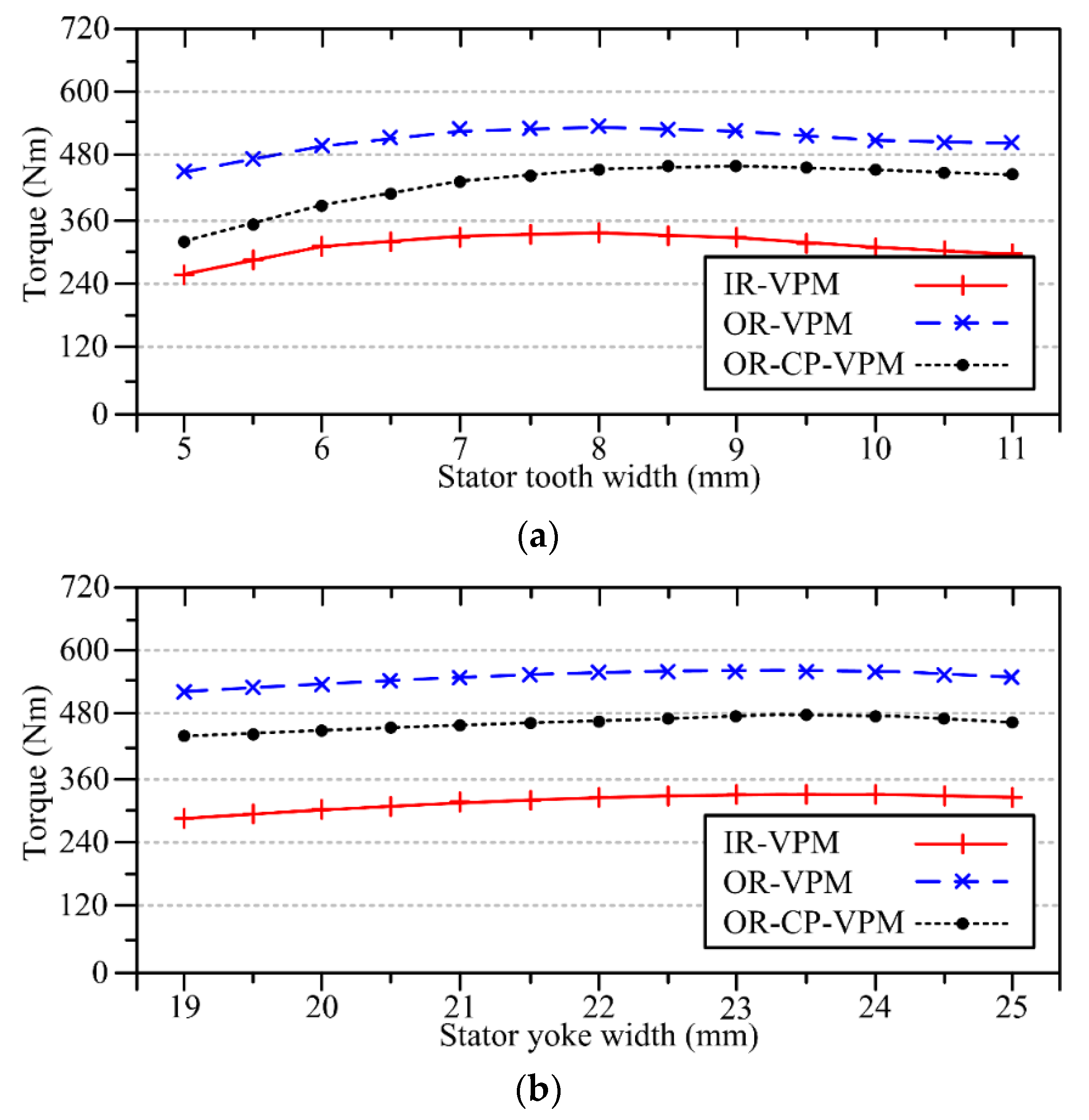
The variations of the torque performances with the stator tooth widths of the proposed VPM motors are shown in
Figure 7a. It can be shown the maximum torque capabilities of the IR-VPM, OR-VPM and OR-CP-VPM motors can be achieved when the stator tooth widths are 8 mm, 8 mm and 9 mm, respectively. Based on the optimized stator tooth widths, the variations of the torque performances with the stator yokes of the proposed VPM motors are shown in
Figure 7b. It can be shown the maximum torque capabilities of the VPM motors can be achieved when their corresponding stator yokes are 23 mm, 23 mm and 23.5 mm, respectively.
As a key parameter to determine the motor performances, the split ratio of the VPM motors can be defined as:
The variations of the torque performances with the split ratios of the proposed VPM motors are shown in
Figure 7c. It can be shown the maximum torque capabilities of the IR-VPM, OR-VPM and OR-CP-VPM motors can be achieved when the split ratios are 0.66, 0.64 and 0.66, respectively.
The variations of the torque performances with the PM heights of the proposed VPM motors are shown in
Figure 7d. It can be shown the maximum torque capabilities with of the IR-VPM, OR-VPM and OR-CP-VPM motors can be achieved when the PM heights are 8 mm, 10 mm and 12 mm, respectively. Owing to the consequent-pole structure, the proposed OR-CP-VPM motor consists of one more degree-of-freedom for motor design. To illustrate the effect of the consequent-pole arrangement, the pole arc ratio is defined as:
The variation of the torque performances with the pole arc ratios of the OR-CP-VPM motor are shown in
Figure 7e. It can be shown its maximum torque capability can be achieved when the pole arc ratio is 0.65. Consequently, all three VPM motors can be compared quantitatively with the benchmark IPM motor based on the fair conditions, while their key motor design data are listed in
Table 1.
The major objective of this paper is to offer the quantitative comparisons of the proposed designs, namely toroidal-winding arrangement and consequent-pole structure. In that case, the employment of simulation analysis is more preferable. With support of the well-developed numerical approach, any uncertainties come from manufacturing errors can be eliminated. However, experimental verifications are always indispensable such that the proposed motor will be prototyped with experimental results included in our future papers.
6. Motor Performance Analysis
The no-load EMF waveforms of the proposed VPM motors at base speed of 1200 rpm are shown in
Figure 8. The results show that all VPM motors can produce the no-load EMF waveforms with the highly sinusoidal-like patterns. Consequently, the fundamental design criteria, such as pole-pair arrangement and PM settlement, are confirmed to be correct. In particular, it can also be verified the proposed toroidal-winding arrangement in both OR-VPM and OR-CP-VPM motors can behave similarly as the conventional overlapping-winding does. According to Equation (3), it can be expected all of these motors can generate very smooth torques.
The output torque waveforms of the proposed VPM motors at steady states under rated current of 250 A are shown in
Figure 9. The average torques of the IR-VPM, the OR-VPM and the OR-CP-VPM motors are about 389 Nm, 591 Nm and 511 Nm, respectively. The results show the toroidal-winding arrangement can allow the OR-VPM and OR-CP-VPM motors to produce 51.9% and 31.4% larger torques than the IR-VPM counterpart. In the meantime, it can be found that the torque ripples of the IR-VPM motor, the OR-VPM motor and the OR-CP-VPM motor are about 4.5%, 3.6% and 4.1%, respectively. Consequently, all the torque performances, including average torque values and torque ripple values, are very attractive for HEV applications [
7].
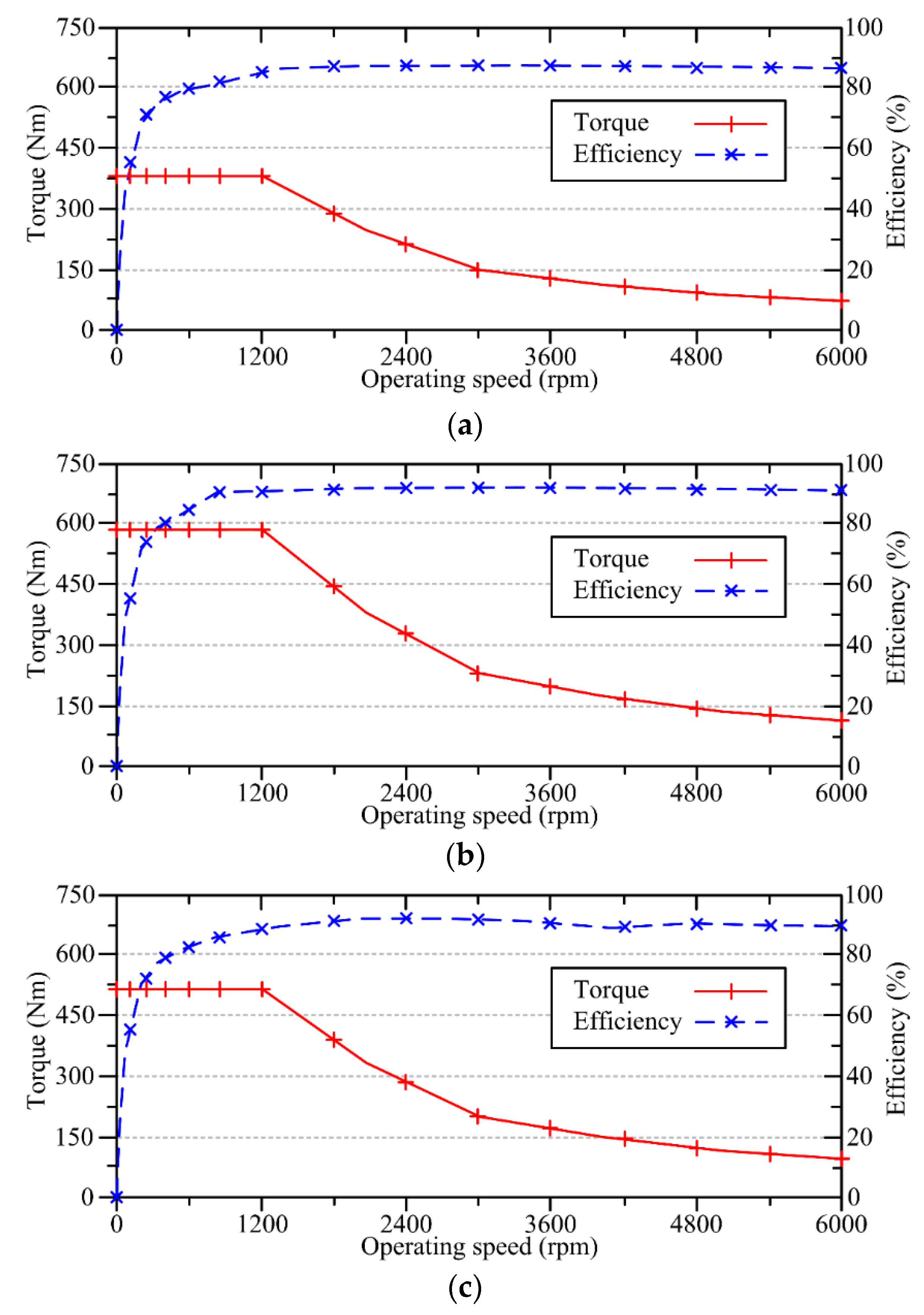
The torque-speed characteristics and the corresponding efficiencies of the proposed VPM motors are shown in
Figure 10. It can be shown that all the proposed VPM motors can achieve excellent flux-weakening capabilities for wide-speed range operations, and it is one of the key criteria for HEV applications. Since the IR-VPM motor employs the overlapping winding-arrangement, it suffers from longer end-winding length and hence lower efficiency than its counterparts. In particular, the IR-VPM motor, the OR-VPM motor and the OR-CP-VPM motor can achieve peak efficiencies as 87%, 92% and 90%, respectively.
7. Evaluation on Motor Performances
All the key performances of the three proposed VPM motors are summarized in
Table 2. To further illustrate the effectiveness and merits of the proposed VPM motors, the profound benchmark IPM motor is included for comparisons. The major characteristics of the proposed VPM motors are fairly compared to the benchmark IPM motor, while a more comprehensive evaluation among these four motors should be further discussed.
With the outer-rotor inner-stator topologies, the OR-VPM and OR-CP-VPM motors can utilize the toroidal-winding arrangement to improve fill winding factors and end-winding lengths. Consequently, both these two motors can outperform its IR-VPM counterpart regarding efficiency, power and torque densities. These features are highly desirable for high-end HEV applications. Apart from high torque density, a modern HEV also requires a smooth torque production. Regarding this aspect, all three proposed VPM motors are able to provide very attractive performances.
As one of the major factors that affect the HEV penetration rate, the cost-effectiveness should also be carefully studied [
30]. The key motor material costs, namely laminated iron, PM material and copper, can be found based on the raw material price in domestic market. Consequently, the cost-effectiveness among the proposed VPM motors, as expressed by power per cost and torque per cost, can be calculated and compared. To be specific, with the support of the consequent-pole structure, the OR-CP-VPM motor can achieve the highest cost-effectiveness of 439 W/USD and 3.5 Nm/USD, as compared with that from IR-VPM motor of 341 W/USD and 2.7 Nm/USD and OR-VPM motor of 358 W/USD and 2.9 Nm/USD.
Since the IR-VPM motor employs the overlapping-winding arrangement, it suffers from higher manufacturing complexity than its toroidal-winding counterparts. In addition, the OR-CP-VPM motor utilizes the consequent-pole settlement for PM installation. Consequently, it further improves its mechanical integrity over the other candidates.
To offer a more illustrative evaluation for the proposed VPM motors, a score grading system is employed as shown in
Table 3. The grading system includes five key performance indices (KPIs) while each of them is graded from score 1 to 5, with 1 as the worst and 5 as the best. Five KPIs, namely efficiency, power density, torque quality, cost-effectiveness and mechanical robustness, are utilized for motor evaluations. In particular, the first four KPIs can be evaluated quantitatively based on the motor performances listed on
Table 2, while the last KPI can only be evaluated based on qualitative arguments. As a result, when taking all the KPIs into considerations, the OR-CP-VPM motor will result as the most capable candidate for HEV applications.
8. Conclusions
In this paper, three VPM motors, namely the IR-VPM, OR-VPM and OR-CP-VPM motors have been analyzed and compared quantitatively with the well-known IPM motor. Upon the employment of outer-rotor structure and toroidal-winding arrangement, the OR-VPM and OR-CP-VPM motors can both achieve higher efficiency, larger power and torque densities than its IR-VPM counterpart. Furthermore, with the implementation of consequent-pole topology, the OR-CP-VPM motor can enjoy comparable power density, better cost-effectiveness and higher mechanical integrity than its counterparts. By taking all the important criteria into accounts, the OR-CP-VPM motor can be perceived as an outstanding candidate for HEV applications. As compared with other profound candidates, the researches on VPM motors are still at the beginning stage. Owing to its absolute merits over its counterparts, it can be foreseen more attentions will be given on this particular motor type. The major problems that exist in VPM motor come from its PM material cost, PM flux leakage and manufacturing complexity. The proposed OR-CP-VPM topology has served as a good starting point to resolve the problems, while it is worthwhile to make more efforts to further improve these shortcomings.
Author Contributions
Conceptualization, C.H.T.L., M.A., K.K.B., M.Q., J.M., S.M., J.L.K. and K.L.V.I.; Investigation, K.K.B, J.M., K.L.V.I.; Writing-Review & Editing, C.H.T.L. and K.L.V.I.; Supervision, J.L.K.; Project Administration, K.L.V.I. and J.J.S.; Funding Acquisition, C.H.T.L. and J.L.K.
Funding
This research was funded by Croucher Foundation, Hong Kong Special Administrative Region, China and Manga International Inc., Troy, MI 48098, USA.
Conflicts of Interest
The authors declare no conflicts of interest.
Nomenclature
| B(θ) | airgap flux density distribution |
| DSPM | doubly-salient permanent-magnet |
| e(t) | back electromotive force |
| EMF | electromotive force |
| f | operating frequency |
| FEM | finite element method |
| FRPM | flux-reversal permanent-magnet |
| FSPM | flux-switching permanent-magnet |
| hPM | PM height |
| HEV | hybrid electric vehicle |
| i(t) | phase current |
| IPM | interior permanent-magnet |
| IR-VPM | inner-rotor Vernier permanent-magnet |
| kp | pole arc ratio |
| ks | split ratio |
| KT | torque ripple factor |
| L | stack length |
| N(θ) | phase winding function |
| n | operating speed |
| OR-CP-VPM | outer-rotor consequent-pole Vernier permanent-magnet |
| OR-VPM | outer-rotor Vernier permanent-magnet |
| Pr | number of rotor PM pole-pairs |
| Ps | number of stator pole-pairs |
| rg | airgap radius |
| rin | motor inner radius |
| rout | motor outer radius |
| Tavg | average torque |
| Tmax | maximum torque |
| Tmin | minimum torque |
| wt | stator tooth width |
| wy | stator yoke width |
| VPM | Vernier permanent-magnet |
| Z | number of stator slots |
| βPM | PM pole pitch |
| βp | pole pitch |
References
- Chan, C.C. The state of the art of electric, hybrid, and fuel cell vehicles. Proc. IEEE 2007, 95, 704–718. [Google Scholar] [CrossRef]
- Emadi, A.; Lee, Y.J.; Rajashekara, K. Power electronics and motor drives in electric, hybrid electric, and plug-in hybrid electric vehicles. IEEE Trans. Ind. Electron. 2008, 55, 2237–2245. [Google Scholar] [CrossRef]
- Silvas, E.; Hofman, T.; Murgovski, N.; Etman, L.F.P.; Steinbuch, M. Review of optimization strategies for system-level design in hybrid electric vehicles. IEEE Trans. Veh. Technol. 2017, 66, 57–70. [Google Scholar] [CrossRef]
- Martinez, C.M.; Hu, X.; Cao, D.; Velenis, E.; Gao, B.; Wellers, M. Energy management in plug-in hybrid electric vehicles: Recent progress and a connected vehicle perspective. IEEE Trans. Veh. Technol. 2017, 66, 4534–4549. [Google Scholar] [CrossRef]
- Cheng, M.; Hua, W.; Zhang, J.; Zhao, W. Overview of stator-permanent magnet brushless machines. IEEE Trans. Ind. Electron. 2011, 58, 5087–5101. [Google Scholar] [CrossRef]
- Tenconi, A.; Vaschetto, S.; Vigliani, A. Electrical machines for high-speed applications: Design considerations and tradeoffs. IEEE Trans. Ind. Electron. 2014, 61, 3022–3029. [Google Scholar] [CrossRef]
- Chau, K.T. Electric Vehicle Machines and Drives—Design, Analysis and Application; Wiley: New York, NY, USA, 2015. [Google Scholar]
- Zheng, P.; Wu, F.; Lei, Y.; Sui, Y.; Yu, B. Investigation of a novel 24-slot/14-pole six-phase fault-tolerant modular permanent-magnet in-wheel motor for electric vehicles. Energies 2013, 6, 4980–5002. [Google Scholar] [CrossRef]
- Lee, C.H.T.; Kirtley, J.L.; Angle, M. A partitioned-stator flux-switching permanent-magnet machine with mechanical flux adjusters for hybrid electric vehicles. IEEE Trans. Magn. 2017, 53, 3000807. [Google Scholar] [CrossRef]
- Cheng, M.; Chau, K.T.; Chan, C.C. Static characteristics of a new doubly salient permanent magnet motor. IEEE Trans. Energy Convers. 2001, 16, 20–25. [Google Scholar] [CrossRef] [Green Version]
- Kim, T.H.; Lee, J. A study of the design for the flux reversal machine. IEEE Trans. Magn. 2004, 40, 2053–2055. [Google Scholar] [CrossRef]
- Zhao, J.; Zheng, Y.; Zhu, C.; Liu, X.; Li, B. A novel modular-stator outer-rotor flux-switching permanent-magnet motor. Energies 2017, 10, 937. [Google Scholar] [CrossRef]
- Cao, R.; Mi, C.; Cheng, M. Quantitative comparison of flux-switching permanent-magnet motors with Interior permanent magnet motor for EV, HEV, and PHEV applications. IEEE Trans. Magn. 2008, 48, 2374–2384. [Google Scholar] [CrossRef]
- Kim, B. Design of a PM Vernier Machine with Consideration for Modulation Flux and Comparison with Conventional PM motors. Energies 2017, 10, 1819. [Google Scholar] [CrossRef]
- Ishizaki, A.; Tanaka, T.; Takasaki, K.; Nishikata, S. Theory and optimum design of PM Vernier motor. In Proceedings of the 1995 Seventh International Conference on Electrical Machines and Drives, Durham, UK, 11–13 September 1995; pp. 208–212. [Google Scholar]
- Kim, B.; Lipo, T. Analysis of a PM Vernier motor with spoke structure. IEEE Trans. Ind. Appl. 2016, 52, 217–225. [Google Scholar] [CrossRef]
- Zhao, F.; Lipo, T.; Kwon, B. A novel dual-stator axial-stator axial-flux spoke-type permanent magnet Vernier machine for direct-drive applications. IEEE Trans. Magn. 2014, 50, 8104304. [Google Scholar] [CrossRef]
- Li, W.; Chau, K.T.; Liu, C.; Gao, S.; Wu, D. Analysis of tooth-tip flux leakage in surface-mounted permanent magnet linear Vernier machines. IEEE Trans. Magn. 2013, 49, 3949–3952. [Google Scholar] [CrossRef] [Green Version]
- Niu, S.; Ho, S.L.; Fu, W.; Wang, L. Quantitative comparison of novel Vernier permanent magnet machines. IEEE Trans. Magn. 2005, 46, 2032–2035. [Google Scholar] [CrossRef]
- Li, J.; Chau, K.T.; Jiang, J.; Liu, C.; Li, W. A new efficient permanent-magnet Vernier machine for wind power generation. IEEE Trans. Magn. 2010, 46, 1475–1478. [Google Scholar] [CrossRef] [Green Version]
- Xu, L.; Liu, G.; Zhao, W.; Yang, X.; Cheng, R. Hybrid stator design of fault-tolerant permanent-magnet Vernier machines for direct-drive applications. IEEE Trans. Ind. Electron. 2017, 64, 179–190. [Google Scholar] [CrossRef]
- Toba, A.; Lipo, T. Novel dual-excitation permanent magnet Vernier machine. In Proceedings of the Conference Record of the 1999 IEEE Industry Applications Conference. Thirty-Forth IAS Annual Meeting (Cat. No.99CH36370), Phoenix, AZ, USA, 3–7 October 1999; pp. 2539–2544. [Google Scholar]
- Li, X.; Chau, K.T.; Cheng, M.; Kim, B.; Lorenz, R.D. Performance analysis of a flux-concentrating field-modulated permanent-magnet machine for direct-drive applications. IEEE Trans. Magn. 2015, 51, 1–11. [Google Scholar]
- Li, D.; Qu, R.; Zhu, Z. Comparison of halbach and dual-side Vernier permanent magnet machines. IEEE Trans. Magn. 2014, 50, 801–804. [Google Scholar] [CrossRef]
- Li, D.; Qu, R.; Li, J.; Xiao, L.; Wu, L.; Xu, W. Analysis of torque capability and quality in Vernier permanent-magnet machines. IEEE Trans. Ind. Appl. 2016, 52, 125–135. [Google Scholar] [CrossRef]
- Li, D.; Qu, R.; Li, J.; Xu, W. Consequent-pole toroidal-winding outer-rotor Vernier permanent-magnet machines. IEEE Trans. Ind. Appl. 2015, 51, 4470–4481. [Google Scholar] [CrossRef]
- Olszewski, M. Evaluation of the 2004 Toyota Prius Hybrid Synergy Drive System; Oak Ridge National Lab., U.S. Department Energy: Oak Ridge, TN, USA, 2005.
- Lee, C.H.T.; Liu, C.; Chau, K.T. A magnetless axial-flux machine for range-extended electric vehicle. Energies 2014, 7, 1483–1499. [Google Scholar] [CrossRef] [Green Version]
- Zhu, X.; Xiang, Z.; Zhang, C.; Quan, L.; Du, Y.; Gu, W. Co-reduction of torque ripple for outer rotor flux-switching PM motor using systematic multi-level design and control schemes. IEEE Trans. Ind. Electron. 2017, 64, 1101–1112. [Google Scholar] [CrossRef]
- Lee, C.H.T.; Chau, K.T.; Liu, C. Design and analysis of an electronic-geared magnetless machine for electric vehicles. IEEE Trans. Ind. Electron. 2016, 63, 6705–6714. [Google Scholar] [CrossRef]
© 2018 by the authors. Licensee MDPI, Basel, Switzerland. This article is an open access article distributed under the terms and conditions of the Creative Commons Attribution (CC BY) license (http://creativecommons.org/licenses/by/4.0/).

 ,
, 


