Maximum Power Extraction from a Partially Shaded PV System Using an Interleaved Boost Converter


Abstract
:1. Introduction
2. Description of the PSPV Systems with and without IBC
2.1. Grid-Connected PSPV Energy System with CBC
2.2. Grid-Connected PSPV Energy System with IBC
3. Maximum Power Point Tracking under Partial Shading Conditions
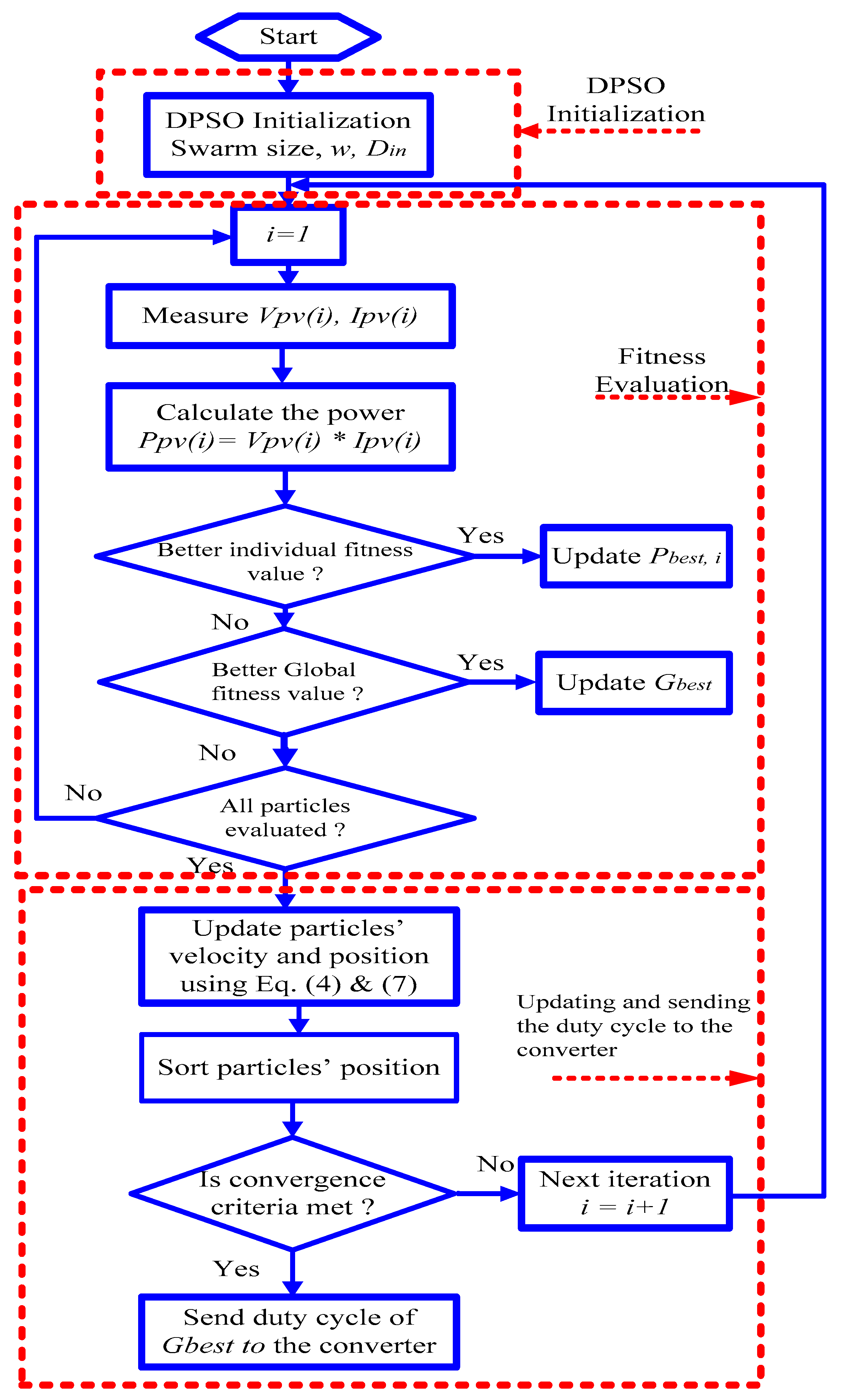
3.1. Particle Swarm Optimization Technique
- Step 1 (DPSO initialization): Send the initial duty cycles to CBC of the PSPV system one by one and collect the related power values.
- Step 2 (Updating the velocity and position of particles): Update the position and velocity for each particle using Equations (4), and (7), respectively, and consequently get the new values of duty cycles.
- Step 3 (Fitness evaluation): Send the new values of duty cycles to the PSPV system and collect the related power values.
- Step 4 Evaluate the Pbest,i, Gbest and their associated particle’s position (duty cycles), then; go back to Step 2.
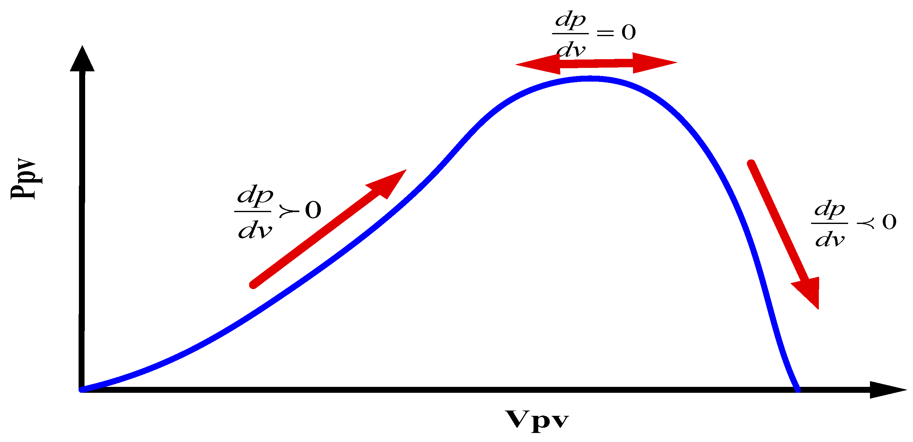
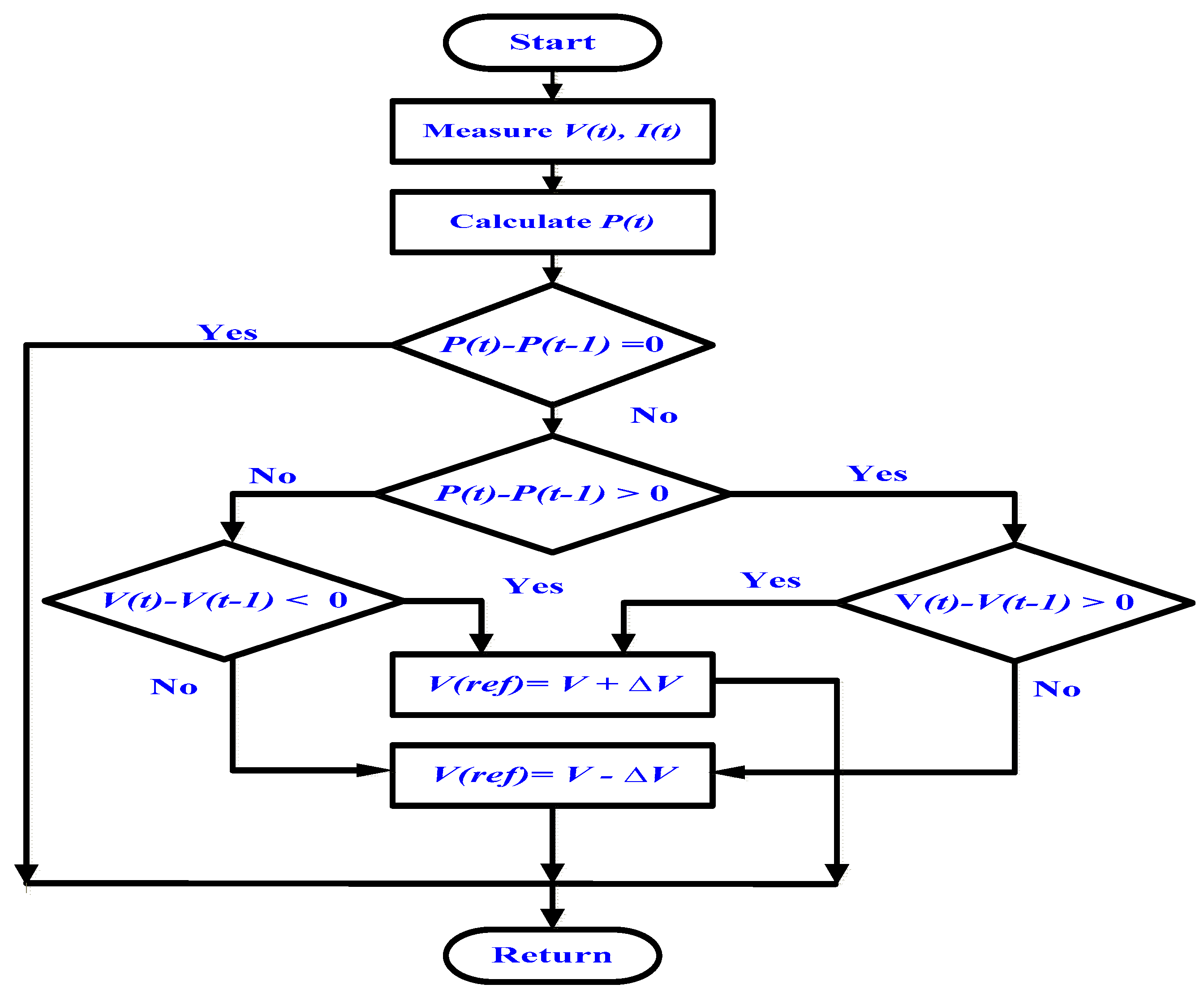
3.2. Perturb and Observe Technique
4. Simulation Results and Discussion
5. Conclusions
Author Contributions
Funding
Conflicts of Interest
Nomenclature
| xik | Position vector of PSO; |
| vik | Velocity vector of PSO; |
| ω | Inertia weight; |
| c1 and c2 | The acceleration coefficients; |
| VPV (i) | PV voltage for each particle; |
| IPV (i) | PV current for each particle; |
| PPV (i) | PV output power for each particle; |
| dP/dV | Slope of the P-V curve; |
| IMPP | Current at maximum power point; |
| VMPP | Voltage at maximum power point; |
| MP | Maximum power generated; |
| Ir | irradiance (W/m2); |
| MML | Mismatch loss index; |
| PSPV | Partially Shaded Photovoltaic; |
| GP | global peak; |
| LPs | local peaks; |
| MPPT | Maximum Power Point Tracker; |
| IBC | Interleaved Boost Converter; and |
| CBC | Conventional Boost Converter. |
References
- Arunkumari, T.; Indragandhi, V. An overview of high voltage conversion ratio DC-DC converter configurations used in DC micro-grid architectures. Renew. Sustain. Energy Rev. 2017, 77, 670–687. [Google Scholar] [CrossRef]
- Babu, T.S.; Rajasekar, N.; Sangeetha, K. Modified particle swarm optimization technique based maximum power point tracking for uniform and under partial shading condition. Appl. Soft Comput. 2015, 34, 613–624. [Google Scholar] [CrossRef]
- Ashouri-Zadeh, A.; Toulabi, M.; Dobakhshari, A.S.; Taghipour-Broujeni, S.; Ranjbar, A.M. A novel technique to extract the maximum power of photovoltaic array in partial shading conditions. Int. J. Electr. Power Energy Syst. 2018, 101, 500–512. [Google Scholar] [CrossRef]
- Saharia, B.J.; Saharia, K.K. Simulated Study on Nonisolated DC-DC Converters for MPP Tracking for Photovoltaic Power Systems. J. Energy Eng. 2015, 142, 04015001. [Google Scholar] [CrossRef]
- Silvestre, S.; Chouder, A. Effects of shadowing on photovoltaic module performance. Prog. Photovolt. Res. Appl. 2008, 16, 141–149. [Google Scholar] [CrossRef]
- Hemandez, J.; Garcia, O.; Jurado, F. Photovoltaic devices under partial shading conditions. Int. Rev. Model. Simul. 2012, 5, 414–425. [Google Scholar]
- Eltamaly, A.M. Performance of smart maximum power point tracker under partial shading conditions of photovoltaic systems. J. Renew. Sustain. Energy 2015, 7, 043141. [Google Scholar] [CrossRef]
- Duong, M.Q.; Sava, G.N.; Ionescu, G.; Necula, H.; Leva, S.; Mussetta, M. Optimal bypass diode configuration for PV arrays under shading influence. In Proceedings of the 2017 IEEE International Conference on Environment and Electrical Engineering and 2017 IEEE Industrial and Commercial Power Systems Europe (EEEIC/I & CPS Europe), Milan, Italy, 6–9 June 2017; pp. 1–5. [Google Scholar]
- Rezk, H.; Eltamaly, A.M. A comprehensive comparison of different MPPT techniques for photovoltaic systems. Sol. Energy 2015, 112, 1–11. [Google Scholar] [CrossRef]
- Islam, H.; Mekhilef, S.; Shah, N.B.M.; Soon, T.K.; Seyedmahmousian, M.; Horan, B.; Stojcevski, A. Performance evaluation of maximum power point tracking approaches and photovoltaic systems. Energies 2018, 11, 365. [Google Scholar] [CrossRef]
- Zainuri, M.A.A.M.; Radzi, M.A.M.; Soh, A.C.; Rahim, N.A. Development of adaptive perturb and observe-fuzzy control maximum power point tracking for photovoltaic boost DC–DC converter. IET Renew. Power Gener. 2013, 8, 183–194. [Google Scholar] [CrossRef]
- De Brito, M.A.G.; Galotto, L.; Sampaio, L.P.; Melo, G.d.A.; Canesin, C.A. Evaluation of the main MPPT techniques for photovoltaic applications. IEEE Trans. Ind. Electron. 2013, 60, 1156–1167. [Google Scholar] [CrossRef]
- Ishaque, K.; Salam, Z.; Lauss, G. The performance of perturb and observe and incremental conductance maximum power point tracking method under dynamic weather conditions. Appl. Energy 2014, 119, 228–236. [Google Scholar] [CrossRef]
- Ahmed, J.; Salam, Z. An improved perturb and observe (P&O) maximum power point tracking (MPPT) algorithm for higher efficiency. Appl. Energy 2015, 150, 97–108. [Google Scholar]
- Seyedmahmoudian, M.; Horan, B.; Rahmani, R.; Maung Than Oo, A.; Stojcevski, A. Efficient photovoltaic system maximum power point tracking using a new technique. Energies 2016, 9, 147. [Google Scholar] [CrossRef]
- Teo, J.; Tan, R.H.; Mok, V.; Ramachandaramurthy, V.K.; Tan, C. Impact of Partial Shading on the PV Characteristics and the Maximum Power of a Photovoltaic String. Energies 2018, 11, 1860. [Google Scholar] [CrossRef]
- Ishaque, K.; Salam, Z.; Shamsudin, A.; Amjad, M. A direct control based maximum power point tracking method for photovoltaic system under partial shading conditions using particle swarm optimization algorithm. Appl. Energy 2012, 99, 414–422. [Google Scholar] [CrossRef]
- Bidram, A.; Davoudi, A.; Balog, R.S. Control and circuit techniques to mitigate partial shading effects in photovoltaic arrays. IEEE J. Photovolt. 2012, 2, 532–546. [Google Scholar] [CrossRef]
- Balasubramanian, I.R.; Ganesan, S.I.; Chilakapati, N. Impact of partial shading on the output power of PV systems under partial shading conditions. IET Power Electron. 2013, 7, 657–666. [Google Scholar] [CrossRef]
- Ali, A.I.M.; Sayed, M.A.; Mohamed, E.E.M. Modified efficient perturb and observe maximum power point tracking technique for grid-tied PV system. Int. J. Electr. Power Energy Syst. 2018, 99, 192–202. [Google Scholar] [CrossRef]
- Ji, Y.-H.; Jung, D.-Y.; Kim, J.-G.; Kim, J.-H.; Lee, T.-W.; Won, C.-Y. A real maximum power point tracking method for mismatching compensation in PV array under partially shaded conditions. IEEE Trans. Power Electron. 2011, 26, 1001–1009. [Google Scholar] [CrossRef]
- Titri, S.; Larbes, C.; Toumi, K.Y.; Benatchba, K. A new MPPT controller based on the Ant colony optimization algorithm for Photovoltaic systems under partial shading conditions. Appl. Soft Comput. 2017, 58, 465–479. [Google Scholar] [CrossRef]
- Ishaque, K.; Salam, Z.; Amjad, M.; Mekhilef, S. An improved particle swarm optimization (PSO)–based MPPT for PV with reduced steady-state oscillation. IEEE Trans. Power Electron. 2012, 27, 3627–3638. [Google Scholar] [CrossRef]
- Ishaque, K.; Salam, Z. A review of maximum power point tracking techniques of PV system for uniform insolation and partial shading condition. Renew. Sustain. Energy Rev. 2013, 19, 475–488. [Google Scholar] [CrossRef]
- Ishaque, K.; Salam, Z. A deterministic particle swarm optimization maximum power point tracker for photovoltaic system under partial shading condition. IEEE Trans. Ind. Electron. 2013, 60, 3195–3206. [Google Scholar] [CrossRef]
- Khare, A.; Rangnekar, S. A review of particle swarm optimization and its applications in solar photovoltaic system. Appl. Soft Comput. 2013, 13, 2997–3006. [Google Scholar] [CrossRef]
- Miyatake, M.; Toriumi, F.; Endo, T.; Fujii, N. A Novel maximum power point tracker controlling several converters connected to photovoltaic arrays with particle swarm optimization technique. In Proceedings of the 2007 European conference on Power Electronics and Applications, Aalborg, Denmark, 2–5 September 2007; pp. 1–10. [Google Scholar]
- Ishaque, K.; Salam, Z.; Taheri, H.; Shamsudin, A. Maximum power point tracking for PV system under partial shading condition via particle swarm optimization. In Proceedings of the 2011 IEEE Applied Power Electronics Colloquium (IAPEC), Johor Bahru, Malaysia, 18–19 April 2011; pp. 5–9. [Google Scholar]
- Sarvi, M.; Ahmadi, S.; Abdi, S. A PSO-based maximum power point tracking for photovoltaic systems under environmental and partially shaded conditions. Prog. Photovolt. Res. Appl. 2015, 23, 201–214. [Google Scholar] [CrossRef]
- Chekired, F.; Mellit, A.; Kalogirou, S.; Larbes, C. Intelligent maximum power point trackers for photovoltaic applications using FPGA chip: A comparative study. Sol. Energy 2014, 101, 83–99. [Google Scholar] [CrossRef]
- Kamarzaman, N.A.; Tan, C.W. A comprehensive review of maximum power point tracking algorithms for photovoltaic systems. Renew. Sustain. Energy Rev. 2014, 37, 585–598. [Google Scholar] [CrossRef]
- Messai, A.; Mellit, A.; Guessoum, A.; Kalogirou, S. Maximum power point tracking using a GA optimized fuzzy logic controller and its FPGA implementation. Sol. Energy 2011, 85, 265–277. [Google Scholar] [CrossRef]
- Eltamaly, A.M. Modeling of fuzzy logic controller for photovoltaic maximum power point tracker. In Proceedings of the Solar Future 2010 Conference, Istanbul, Turkey, 12 February 2010. [Google Scholar]
- Chang, L.-Y.; Chao, K.-H.; Chang, T.-C. A High Voltage Ratio and Low Ripple Interleaved DC-DC Converter for Fuel Cell Applications. Sci. World J. 2012, 2012, 896508. [Google Scholar] [CrossRef] [PubMed]
- De Assis Sobreira, P., Jr.; Tofoli, F.L.; Braga, H.A.C.; Barbosa, P.G.; Ferreira, A.A. Analysis of mppt techniques applied to the dcm multiphase boost converter for the mitigation of partial shading in PV arrays. Eletrôn. Potên. 2013, 18, 1138–1148. [Google Scholar] [CrossRef]
- Coruh, N.; Urgun, S.; Erfidan, T.; Ozturk, S. A simple and efficient implemantation of interleaved boost converter. In Proceedings of the 2011 6th IEEE Conference on Industrial Electronics and Applications (ICIEA), Beijing, China, 21–23 June 2011; pp. 2364–2368. [Google Scholar]
- Lee, P.-W.; Lee, Y.-S.; Cheng, D.K.; Liu, X.-C. Steady-state analysis of an interleaved boost converter with coupled inductors. IEEE Trans. Ind. Electron. 2000, 47, 787–795. [Google Scholar] [CrossRef]
- Liccardo, F.; Marino, P.; Torre, G.; Triggianese, M. Interleaved dc-dc converters for photovoltaic modules. In Proceedings of the 2007 ICCEP’07, International Conference on Clean Electrical Power, Capri, Itlay, 21–23 May 2007; pp. 201–207. [Google Scholar]
- Sri Revathi, B.; Prabhakar, M. Non isolated high gain DC-DC converter topologies for PV applications—A comprehensive review. Renew. Sustain. Energy Rev. 2016, 66, 920–933. [Google Scholar] [CrossRef]
- Garth, D.R.; Muldoon, W.; Benson, G.; Costague, E. Multi-phase, 2-kilowatt, high-voltage, regulated power supply. In Proceedings of the 1971 IEEE Power Electronics Specialists Conference, Pasadena, CA, USA, 19–20 April 1971; pp. 110–116. [Google Scholar]
- Benyahia, N.; Denoun, H.; Badji, A.; Zaouia, M.; Rekioua, T.; Benamrouche, N.; Rekioua, D. MPPT controller for an interleaved boost dc–dc converter used in fuel cell electric vehicles. Int. J. Hydrogen Energy 2014, 39, 15196–15205. [Google Scholar] [CrossRef]
- Arango, E.; Ramos-Paja, C.A.; Calvente, J.; Giral, R.; Serna, S. Asymmetrical interleaved DC/DC switching converters for photovoltaic and fuel cell applications—Part 1: Circuit generation, analysis and design. Energies 2012, 5, 4590–4623. [Google Scholar] [CrossRef]
- Deihimi, A.; Mahmoodieh, M.E.S.; Iravani, R. A new multi-input step-up DC–DC converter for hybrid energy systems. Electr. Power Syst. Res. 2017, 149, 111–124. [Google Scholar] [CrossRef]
- Mohapatra, A.; Nayak, B.; Das, P.; Mohanty, K.B. A review on MPPT techniques of PV system under partial shading condition. Renew. Sustain. Energy Rev. 2017, 80, 854–867. [Google Scholar] [CrossRef]
- Lakpathi, G.; Reddy, S.M.; Ganesh, K.L.; Satyanarayana, G. An effective high step-up interleaved DC-DC converter photovoltaic grid connection System. Int. J. Soft Comput. Eng. (IJSCE) 2013, 3, 2231–2307. [Google Scholar]
- Khadmun, W.; Subsingha, W. High Voltage Gain Interleaved DC Boost Converter Application for Photovoltaic Generation System. Energy Procedia 2013, 34, 390–398. [Google Scholar] [CrossRef]
- Khosroshahi, A.; Abapour, M.; Sabahi, M. Reliability evaluation of conventional and interleaved DC–DC boost converters. IEEE Trans. Power Electron. 2015, 30, 5821–5828. [Google Scholar] [CrossRef]
- Henn, G.A.; Silva, R.; Praca, P.P.; Barreto, L.H.; Oliveira, D.S. Interleaved-boost converter with high voltage gain. IEEE Trans. Power Electron. 2010, 25, 2753–2761. [Google Scholar] [CrossRef]
- Yang, B.; Li, W.; Zhao, Y.; He, X. Design and analysis of a grid-connected photovoltaic power system. IEEE Trans. Power Electron. 2010, 25, 992–1000. [Google Scholar] [CrossRef]
- Ramaprabha, R.; Balaji, K.; Raj, S.; Logeshwaran, V. Comparison of interleaved boost converter configurations for solar photovoltaic system interface. J. Eng. Res. [TJER] 2013, 10, 87–98. [Google Scholar] [CrossRef]
- Prasanth, P.; Seyezhai, R. Investigation of four phase interleaved boost converter under open loop and closed loop control schemes for battery charging applications. Int. J. Adv. Materi. Sci. Eng. (IJAMSE) 2016, 5, 2201–2311. [Google Scholar] [CrossRef]
- Aghdam, F.H.; Hagh, M.T.; Abapour, M. Reliability evaluation of two-stage interleaved boost converter interfacing PV panels based on mode of use. In Proceedings of the 2016 7th Power Electronics and Drive Systems Technologies Conference (PEDSTC), Tehran, Iran, 16–18 February 2016; pp. 409–414. [Google Scholar]
- Lai, C.-M.; Cheng, Y.-H.; Teh, J.; Lin, Y.-C. A New Combined Boost Converter with Improved Voltage Gain as a Battery-Powered Front-End Interface for Automotive Audio Amplifiers. Energies 2017, 10, 1128. [Google Scholar] [CrossRef]
- Rehman, Z.; Al-Bahadly, I.; Mukhopadhyay, S. Multiinput DC–DC converters in renewable energy applications—An overview. Renew. Sustain. Energy Rev. 2015, 41, 521–539. [Google Scholar] [CrossRef]
- Ho, C.N.-M.; Breuninger, H.; Pettersson, S.; Escobar, G.; Canales, F. A comparative performance study of an interleaved boost converter using commercial Si and SiC diodes for PV applications. IEEE Trans. Power Electron. 2013, 28, 289–299. [Google Scholar] [CrossRef]
- Mouli, G.R.C.; Schijffelen, J.H.; Bauer, P.; Zeman, M. Design and Comparison of a 10-kW Interleaved Boost Converter for PV Application Using Si and SiC Devices. IEEE J. Emerg. Sel. Top. Power Electron. 2017, 5, 610–623. [Google Scholar] [CrossRef] [Green Version]
- Eltamaly, A.M.; Alolah, A.; Farh, H.M. Maximum power extraction from utility-interfaced wind turbines. In New Developments in Renewable Energy; InTech: London, UK, 2013. [Google Scholar]
- Al-Obeidat, F.; Belacel, N.; Carretero, J.A.; Mahanti, P. Automatic Parameter Settings for the PROAFTN Classifier Using Hybrid Particle Swarm Optimization. In Proceedings of the Canadian Conference on AI, Ottawa, ON, Canada, 31 May–2 June 2010; pp. 184–195. [Google Scholar]
- Liu, Y.; Xia, D.; He, Z. MPPT of a PV system based on the particle swarm optimization. In Proceedings of the 2011 4th International Conference on Electric Utility Deregulation and Restructuring and Power Technologies (DRPT), Weihai, China, 6–9 July 2011; pp. 1094–1096. [Google Scholar]
- Miyatake, M.; Inada, T.; Hiratsuka, I.; Zhao, H.; Otsuka, H.; Nakano, M. Control characteristics of a fibonacci-search-based maximum power point tracker when a photovoltaic array is partially shaded. In Proceedings of the IPEMC 2004, the 4th International Power Electronics and Motion Control Conference, Xi’an, China, 14–16 August 2004; pp. 816–821. [Google Scholar]
- Soltani, I.; Sarvi, M.; Marefatjou, H. An intelligent, fast and robust maximum power point tracking for proton exchange membrane fuel cell. World Appl. Program. 2013, 3, 264–281. [Google Scholar]
- Huang, Y.-P.; Ye, C.-E.; Chen, X. A Modified Firefly Algorithm with Rapid Response Maximum Power Point Tracking for Photovoltaic Systems under Partial Shading Conditions. Energies 2018, 11, 2284. [Google Scholar] [CrossRef]
- Ahmed, J.; Salam, Z. A Maximum Power Point Tracking (MPPT) for PV system using Cuckoo Search with partial shading capability. Appl. Energy 2014, 119, 118–130. [Google Scholar] [CrossRef]
- Chang, L.-Y.; Chung, Y.-N.; Chao, K.-H.; Kao, J.-J. Smart Global Maximum Power Point Tracking Controller of Photovoltaic Module Arrays. Energies 2018, 11, 567. [Google Scholar] [CrossRef]
- Khadidja, S.; Mountassar, M.; M’hamed, B. Comparative study of incremental conductance and perturb & observe MPPT methods for photovoltaic system. In Proceedings of the 2017 International Conference on Green Energy Conversion Systems (GECS), Hammamet, Tunisia, 23–25 March 2017; pp. 1–6. [Google Scholar]
- Sharma, R.S.; Katti, P. Perturb & observation MPPT algorithm for solar photovoltaic system. In Proceedings of the 2017 International Conference on Circuit, Power and Computing Technologies (ICCPCT), Kollam, India, 20–21 April 2017; pp. 1–6. [Google Scholar]


| Maximum power (Pmax) | 185.22 W |
| Cells per Module | 54 |
| Open-circuit voltage (Voc) | 32.2 V |
| Short-circuit current (Isc) | 7.89 A |
| Voltage at maximum power point (VMPP) | 25.2 V |
| Current at maximum power point (IMPP) | 7.35 A |
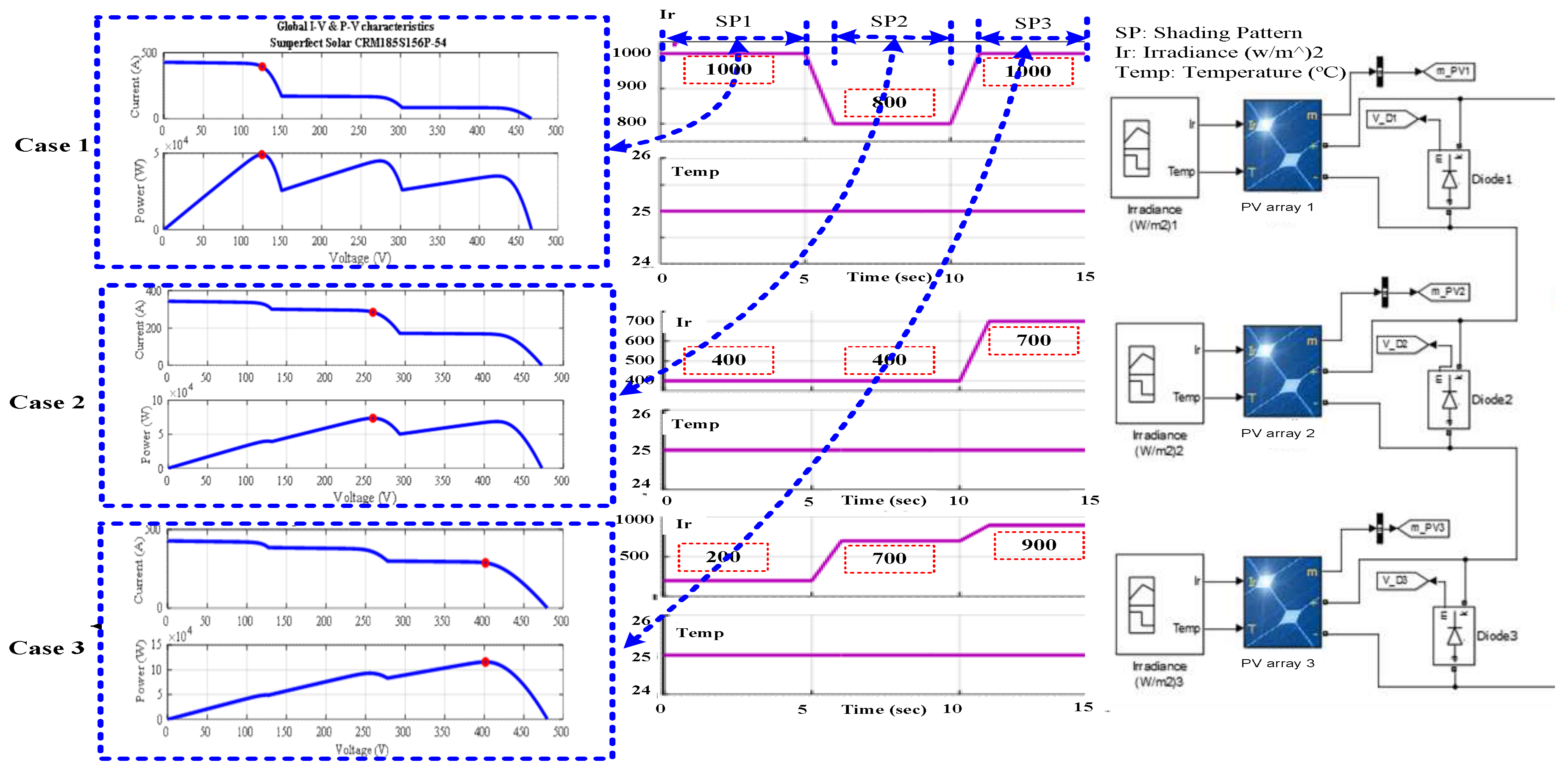
| PS Cases | Case 1 (GP at the Beginning) | Case 2 (GP in the Middle) | Case 3 (GP at the End) | ||||
|---|---|---|---|---|---|---|---|
| Ir (W/m2) | MP (kW) | Ir (W/m2) | MP (kW) | Ir (W/m2) | MP (kW) | ||
| PV arrays | PV array 1 | 1000 | 50 | 800 | 40.5 | 1000 | 50 |
| PV array 2 | 400 | 20.6 | 400 | 20.6 | 700 | 35.6 | |
| PV array 3 | 200 | 10.2 | 700 | 35.6 | 900 | 45.3 | |
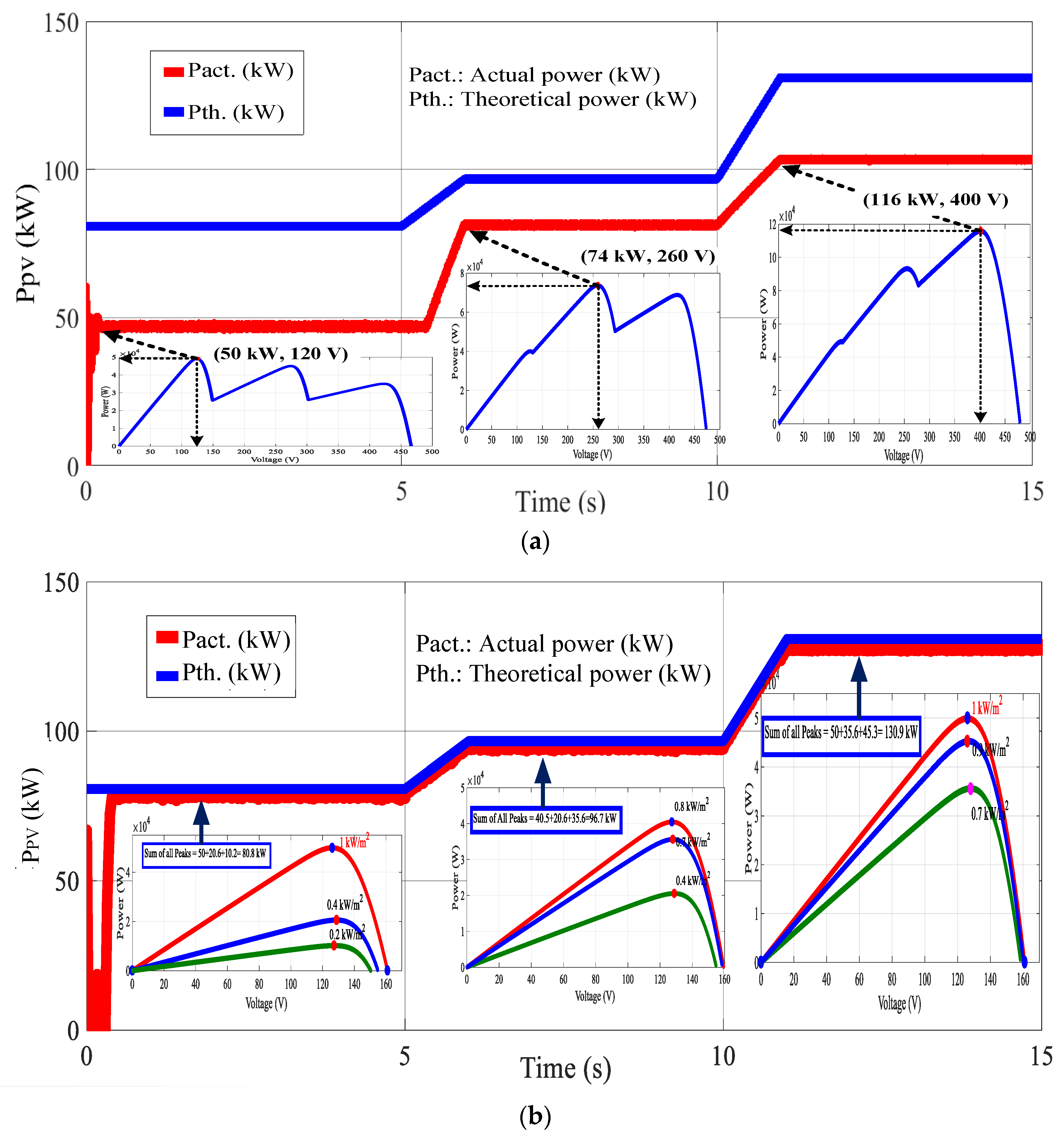
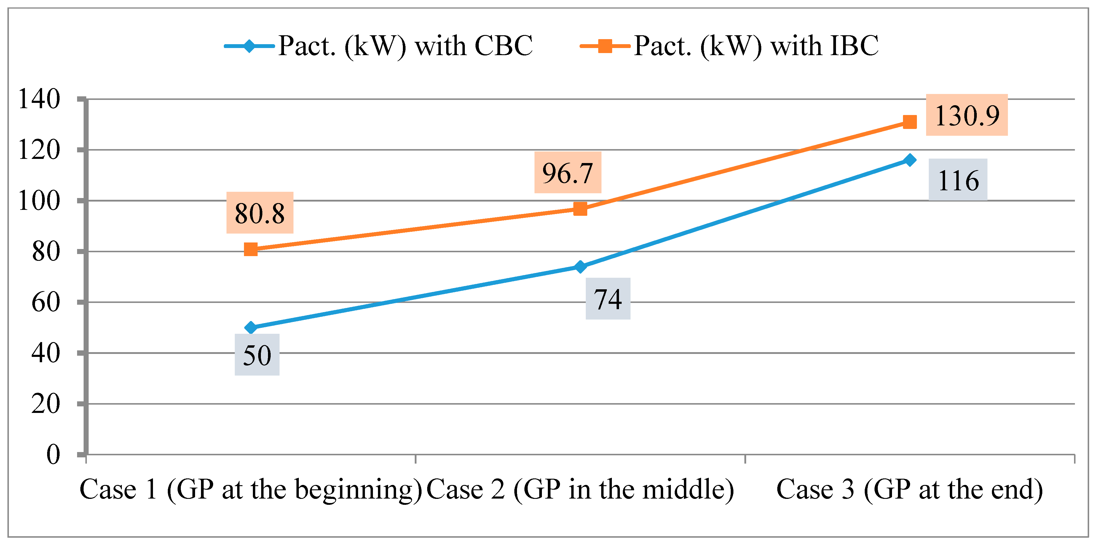
| With CBC | Theoretical Power (kW) | 80.8 | 96.7 | 130.9 | |||
| Actual Power (kW) | 50 | 74 | 116 | ||||
| MML | 38.5% | 40.5% | 44.8% | ||||
| With IBC | Theoretical Power (kW) | 80.8 | 96.7 | 130.9 | |||
| Actual Power (kW) | 80.8 | 96.7 | 130.9 | ||||
| MML | 100% | 100% | 100% | ||||
© 2018 by the authors. Licensee MDPI, Basel, Switzerland. This article is an open access article distributed under the terms and conditions of the Creative Commons Attribution (CC BY) license (http://creativecommons.org/licenses/by/4.0/).
Share and Cite
Farh, H.M.H.; Othman, M.F.; Eltamaly, A.M.; Al-Saud, M.S. Maximum Power Extraction from a Partially Shaded PV System Using an Interleaved Boost Converter. Energies 2018, 11, 2543. https://doi.org/10.3390/en11102543
Farh HMH, Othman MF, Eltamaly AM, Al-Saud MS. Maximum Power Extraction from a Partially Shaded PV System Using an Interleaved Boost Converter. Energies. 2018; 11(10):2543. https://doi.org/10.3390/en11102543
Chicago/Turabian StyleFarh, Hassan M. H., Mohd F. Othman, Ali M. Eltamaly, and M. S. Al-Saud. 2018. "Maximum Power Extraction from a Partially Shaded PV System Using an Interleaved Boost Converter" Energies 11, no. 10: 2543. https://doi.org/10.3390/en11102543