Diagnosis of Inter-Turn Short Circuit of Synchronous Generator Rotor Winding Based on Volterra Kernel Identification


State Key Laboratory of Alternate Electrical Power System with Renewable Energy Sources, North China Electric Power University, Baoding 071003, China
*
Author to whom correspondence should be addressed.
Energies 2018, 11(10), 2524; https://doi.org/10.3390/en11102524
Submission received: 30 August 2018
/
Revised: 7 September 2018
/
Accepted: 20 September 2018
/
Published: 21 September 2018
(This article belongs to the Section I: Energy Fundamentals and Conversion)
Abstract
:The inter-turn short circuit is a common fault in the synchronous generator. This fault is not easily detected at early stage. However, with the development of the fault, it will pose a threat to the safe operation of the generator. To detect the inter-turn short circuit of rotor winding, the feasibility of identifying the stator branch characteristics of synchronous generator during inter-turn short circuit was analyzed. In this paper, an on-line fault identification method based on Volterra kernel identification is presented. This method uses the stator branch voltage and stator unbalance branch current collected from the generator as input and output signals of the series model. Recursive batch least squares method is applied to calculate the three kernels of Volterra series. When the generator is in normal state or fault state, the Volterra kernel will change accordingly. Through the identification of the time-domain kernel of the nonlinear transfer model, the inter-turn short circuit fault of the synchronous generator is diagnosed. The correctness and effectiveness of this method is verified by using the data of fault experimental synchronous generator.
1. Introduction
Rotor winding inter-turn short circuit fault is a typical fault in synchronous generator. Synchronous generator has the characteristics of complex structure, high voltage and large workload. In addition, the rotor of the generator is in a state of rotational vibration for a long time, thus is more prone to failure. The inter-turn short circuit fault of rotor windings is more common. Most synchronous generators have occurred excitation winding inter-turn short circuit fault or been under the fault condition [1,2]. With the gradual increase of the capacity of the synchronous generator, the requirement for its reliability is also increasing. When the inter-turn short circuit occurs in the rotor winding of large synchronous generator, it will result in the increase of excitation current and the intensification of rotor vibration [3,4]. In the early stage, the fault characteristics of inter-turn short circuit of excitation winding are too small to be identified easily. If the rotor winding inter-turn short circuit fault cannot be dealt with as soon as possible, it may develop into a serious accident and pose a great threat to the safe operation of the generator and the power grid. The safe and stable operation of synchronous generator is the key to ensure the reliable power supply of power system, so it is very necessary to identify the inter-turn short circuit fault of synchronous generator rotor winding in early stage.
Synchronous generator inter-turn short circuit fault diagnosis method can be divided into off-line detection and on-line detection according to whether it affects the normal operation of the generator. At present, off-line detection methods are applied more frequently in practical synchronous generators. For example, the principle of the AC impedance method is to apply AC voltage across the rotor winding [5]. Under the action of AC voltage, the current flowing through the short circuit winding is much larger than the normal current. Short circuit current has strong demagnetization effect. If the AC impedance value of one magnetic pole in the rotor winding is significantly lower than that of the other magnetic poles and the loss is significantly increased, it can be judged that there is inter-turn short circuit in the rotor winding. With more and more synchronous generators running on the grid, the requirements for safe and stable operation of synchronous generators are becoming higher and higher. The original off-line detection method is difficult to meet the requirements of modern real-time monitoring. Therefore, many scholars have proposed the on-line detection method for the inter-turn short circuit of synchronous generator rotor. For example, the detection coil method is used to diagnose inter-turn short circuit fault. Chen et al. [6] calculated the unbalanced magnetic pull force and the air-gap magnetic density after fault, which laid a theoretical foundation for detection coil method. Chen et al. [7] used the detection coil method to diagnose inter-turn short circuit fault of dual-redundancy permanent magnet synchronous motors. Wu et al. [8] installed detection coil on synchronous generator stator. The on-line fault diagnosis is realized by detecting the change of air gap flux after fault. Detection coil method has high diagnostic accuracy, but it is more complicated to add additional detection equipment inside large synchronous generators. Considering the possible interference to synchronous generator, this method is difficult to apply in practice. Maraaba et al. [9] proposed the use of neural networks as an efficient diagnostic tool for estimating the percentage of stator winding shorted turns in three-phase induction motors. However, this method needs more fault motor operation data to support and train. It is not universally applicable to large synchronous generators. Some scholars proposed the multi-loop analysis method for fault detection [10,11]. This method deduces the resistance and inductance matrix according to the connection of each loop of the generator, and calculates the parameters to get the related waveform. There are many poles and damping strips in large hydro-generators, which will make the calculation of related equations complicated, affect the identification accuracy and limit the scope of application. Therefore, in the actual synchronous generator, the accurate diagnosis results may not be obtained by using the multi-loop detection method alone.
Xia et al. [12] established the Volterra model and recognized status of hydraulic turbine runner. In [13], the Volterra kernel function method was used to extract the characteristics of bearing ball wear. Zhao et al. [14] forecasted radiation using a Volterra-least squares support vector machine model combined with signal decomposition. Urresty et al. [15] developed a methodology based on monitoring the zero-sequence voltage component for detecting stator winding inter-turn faults in surface-mounted permanent magnet synchronous motors. Saavedra et al. [16] studied the effects of different stator winding configurations in both the stator currents and the zero-sequence voltage component spectra of healthy and faulty machines. Many parameters will change when synchronous generator occurs inter-turn short circuit. This lays the foundation for subsequent stator unbalance branch current Volterra identification. Mercorelli. [17] proposed an identification technique of the parameters which are needed to minimize power consumption of a city-bus equipped with permanent magnet three-phase synchronous motor. Chen et al. [18] proposed a two-stage Kalman filter combining a robust and optimal algorithm for state and disturbance estimation. Wang et al. [19,20,21,22] established Volterra model and identified its features. However, this study does not consider the inter-turn short circuit fault of rotor winding. The Volterra model is a nonparametric model and can describe most nonlinear systems. The output of its model system is a combination of nonlinear functions input. For any continuous time-invariant nonlinear dynamic system, as long as the input and output of the system are analytic functions, it can be described completely by Volterra series. In practical applications, most nonlinear systems can be described by transitive relations within three orders. Inter-turn short circuit fault is a kind of nonlinear fault, which will lead to the nonlinear change of many electric quantity of synchronous generator. By analyzing previous research [12,13,14,15,16,17,18,19,20,21,22], the Volterra series model can be introduced to describe the system characteristics of the fault.
The stator unbalance branch current will be generated when inter-turn short circuit fault rotor winding occurs in synchronous generator, which can be used as a standard for fault diagnosis. However, the fault characteristics in the generator usually contain interference so that detection is difficult in practice. In this paper, the Volterra series model is established and the feasibility of the stator unbalance current in the model calculation is analyzed. The fault of rotor winding inter-turn short circuit is identified by identifying the difference of Volterra kernel function between the nonlinear system of stator branch voltage and branch current under normal or fault conditions. Conducting the fault experiment of synchronous generator verified the correctness and effectiveness of this method. The method avoids adding equipment to the synchronous generator and therefore has wider range of applications than the detection coil method. In addition, this method combines the advantages of Volterra method and multi-loop method, which reduces the structural analysis of synchronous generator and the computational complexity compared with the direct multi-loop method. Inter-turn short circuit fault will lead to changes of three-order Volterra kernels of stator branch current, so the diagnosis method proposed in this paper can reflect the fault situation from three dimensions and has high diagnostic accuracy. Analyzing Volterra kernel variation of stator branch current of synchronous generator provides important conclusions for early diagnosis of inter-turn short circuit fault.
2. Kernel Identification Algorithm for Volterra Series
The existing fault diagnosis methods based on signal analysis use the output signals obtained by sensors to diagnose. Thus, these methods have some limitations. For some systems, changes in the output signal may sometimes be caused by changes in the input signal or external interference. The fault diagnosis based on the change of the output signal will cause misjudgment. Because, Intrinsic characteristics of the systems have not changed. The Volterra kernel identification method may reflect the transfer characteristics of the system as a whole, which can overcome this deficiency.
2.1. Basic Theory of Volterra Series
Volterra theory was proposed by Italian mathematician Vito Volterra in the study of nonlinear functional, and then Fakhouri established the kernel identification theory [23]. In the case of single input single output, the time-invariant transfer system can be represented by the following formula.
where u(t) is the system input; y(t) is the system output; and F is the functional of the transfer relation between the quantities.
If the system is a nonlinear and time-invariant dynamic system, the system can be expressed as the sum of multiple convolution integrals if the input signal energy is limited. Equation (1) can be rewritten as
where is the k-order time domain output response of the system. hk is the k time domain Volterra kernel of the system, namely k-order generalized impulse response function. The discretization of Equation (2) is
The infinite Volterra series needs to be reduced to a finite number of expressions in practical application.
where is the DC component; K is the highest order in the actual system; Mk is the memory length of the Volterra kernel function of order k; and e(n) is a truncated estimation error. If the order length memory length is appropriate, the error is negligible.
2.2. Kernel Identification of Volterra Series
It is proposed in [24] that most of the nonlinear models in practical electrical engineering applications can be represented by the second-order truncated Volterra series model. Considering the large amount of fourth-order Volterra series calculation, this paper uses the third-order model to diagnose the inter-turn short circuit. Based on the characteristics of the series, the simplified third-order expression is
The expressions of the input quantity U(n) and the kernel vector H(n) of the nonlinear system are defined as follows.
Therefore, the input and output relationship of the third-order Equation (5) for the diagnosis of inter-turn short circuit can be expressed as
Equation (10) is the basis of Volterra time domain kernel identification for inter-turn short circuit fault system. In this paper, the unknown kernel function in the above formula is estimated by recursive least square method [25,26]. The existence of the fault is judged by the difference kernel between the normal function and the fault function.
3. Calculation of Stator Unbalanced Branch Current
The rotor winding is divided into normal excitation circuit and fault additional circuit when the inter-turn short circuit fault occurs in synchronous generator [27,28]. Without considering the saturation of magnetic circuit, the field electromotive force (EMF) after fault is regarded as the superposition of the field EMF generated by normal field loop and the field EMF generated by fault additional loop. The distribution of the magnetomotive force (MMF) generated by the normal excitation circuit is the same under each pole. The MMF under the adjacent poles is reversed due to the opposite winding direction of the excitation winding. The MMF contains fundamental, three and five odd harmonics and repeats on a pair of poles in space. Therefore, the fault MMF analysis can be completed by analyzing the MMF generated by the fault additional loop.
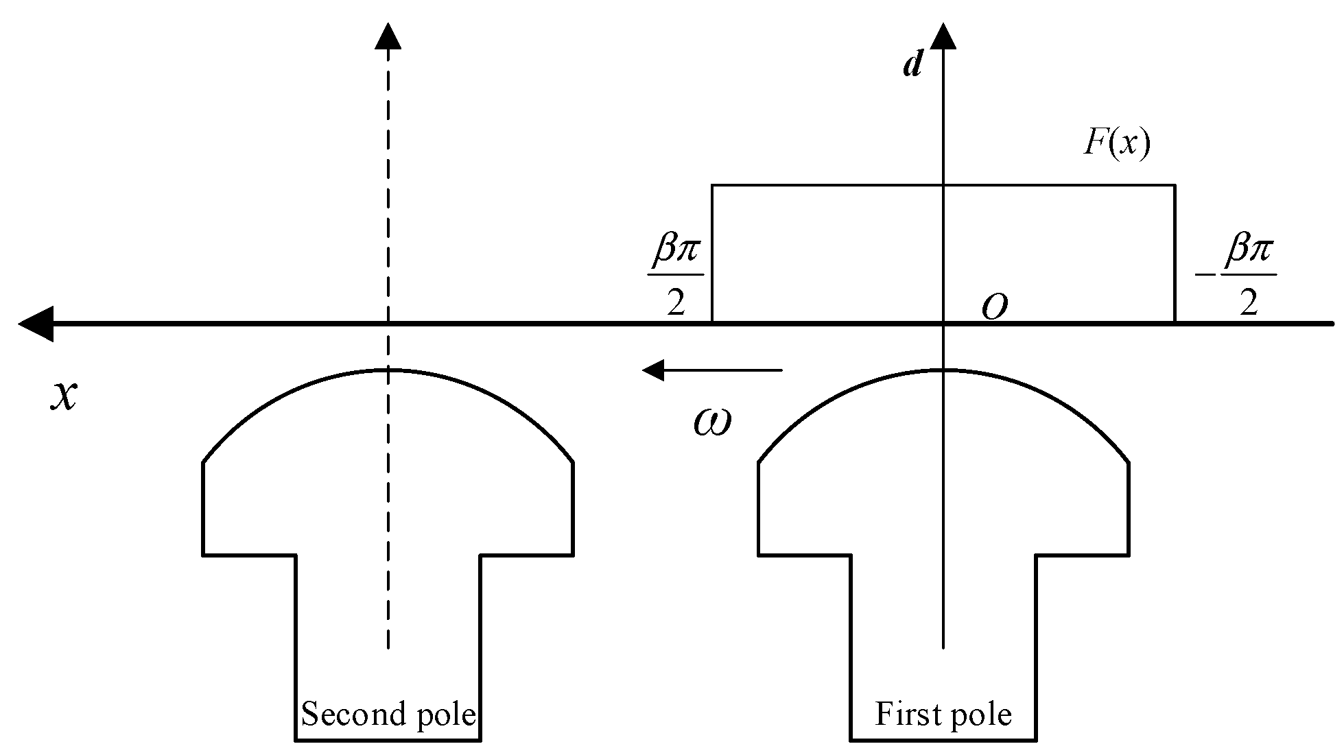
Taking the salient pole synchronous generator as an example, its MMF distribution is shown in Figure 1. The rotation direction of the generator is from right to left. The origin of the coordinate system is taken on the rotor d axis.
It is assumed that ω turns short circuit occurs in the field winding under the first pole. When the winding flows through DC current I, the rectangular wave MMF is generated. Analyzing the harmonic, there is a formula in the [−Pπ, Pπ] interval of the whole generator circle.
where P is number of pole-pairs and x is the coordinate established on the rotor. Since the rectangular MMF is symmetric to the rotor coordinate d, there is only cosine term in Equation (11). The formula can be changed to
where β is the field coil short distance ratio. Since the exciting winding of the salient pole synchronous generator can be regarded as a concentrated range winding, β = 1.
From Equation (13), it can be concluded that, when γ is even number, Fγ = 0. Therefore, the MMF generated by the excitation fault additional loop does not contain even number of harmonics, including fundamental wave, odd number of harmonics and 1/P, 2/P equal number of harmonics.
To arrive at a general conclusion, consider a generator with polar number of P. The n (n > 1) branches of each phase of the generator are spaced two degrees away from each other 2π/n mechanical radians. Therefore, the expression of the μ/P(μ = 1,2,…) current of the A phase branch is
where Ia,μ/P is the effective value of μ/P harmonic current; is synchronous angular frequency; and m = 1, 2, …. It is assumed that the corresponding phase of the generator corresponds to the 2π/3n mechanical arc in space. The corresponding branches of different phases of the generator satisfying this condition are symmetric.
From Equation (14), the μ/P (μ = 1, 2, …) current of the a1 branch is
It can be seen from the above formula that the MMF generated by the fault excitation winding contains fractional harmonics of 1/P, 2/P, etc. The fundamental wave, odd harmonic and 1/P and 2/P fractional harmonics still occur when the MMF acts on the inhomogeneous air gap. Fundamental and odd-order spatial harmonic magnetic fields induce the same phase fundamental and odd-order harmonic currents in the stator branches. However, the fractional spatial harmonic magnetic field induces EMF with different phases in the branches of the same phase of the stator, thereby generating a harmonic unbalance current.
To realize on-line identification of rotor winding inter-turn short circuit fault, the selected diagnosis features should be representative. That is, the characteristic is unique to rotor winding inter-turn short circuit fault. When the external short circuit occurs at the stator end of the synchronous generator, there are only odd harmonics such as fundamental wave, 3 and 5 in the stator steady-state current. When stator inter-turn short circuit or inter-phase short circuit occurs, although the short-circuit stator winding also produces fractional and even-order space harmonic magnetic field, the magnetic field only induces fundamental wave and odd-order harmonic current in the stator. Different harmonic currents will make the results of Volterra kernel identification different, so the rotor winding inter-turn short circuit can be identified by stator branch current. It is worth noting that the two-point grounding fault of the rotor will cause short circuit of the excitation winding. The stator unbalance current characteristic caused by this fault is the same as the inter-turn short circuit of the rotor winding. However, GB/T 14285-2006 “Relay Protection and Safety Automatic Device Technical Regulations” requires that ≥1 MW generators should be equipped with special rotor one-point grounding protection device. Because of imperfect protection and less possibility of two-point grounding fault, there is no special rotor two-point grounding fault protection for generator at present. Considering the harmfulness of rotor two-point grounding fault, if rotor two-point grounding fault occurs, it is also reasonable to diagnose rotor winding inter-turn short circuit fault and make subsequent protection device alarm.
4. The Experiment of Inter-turn Short Circuit Fault
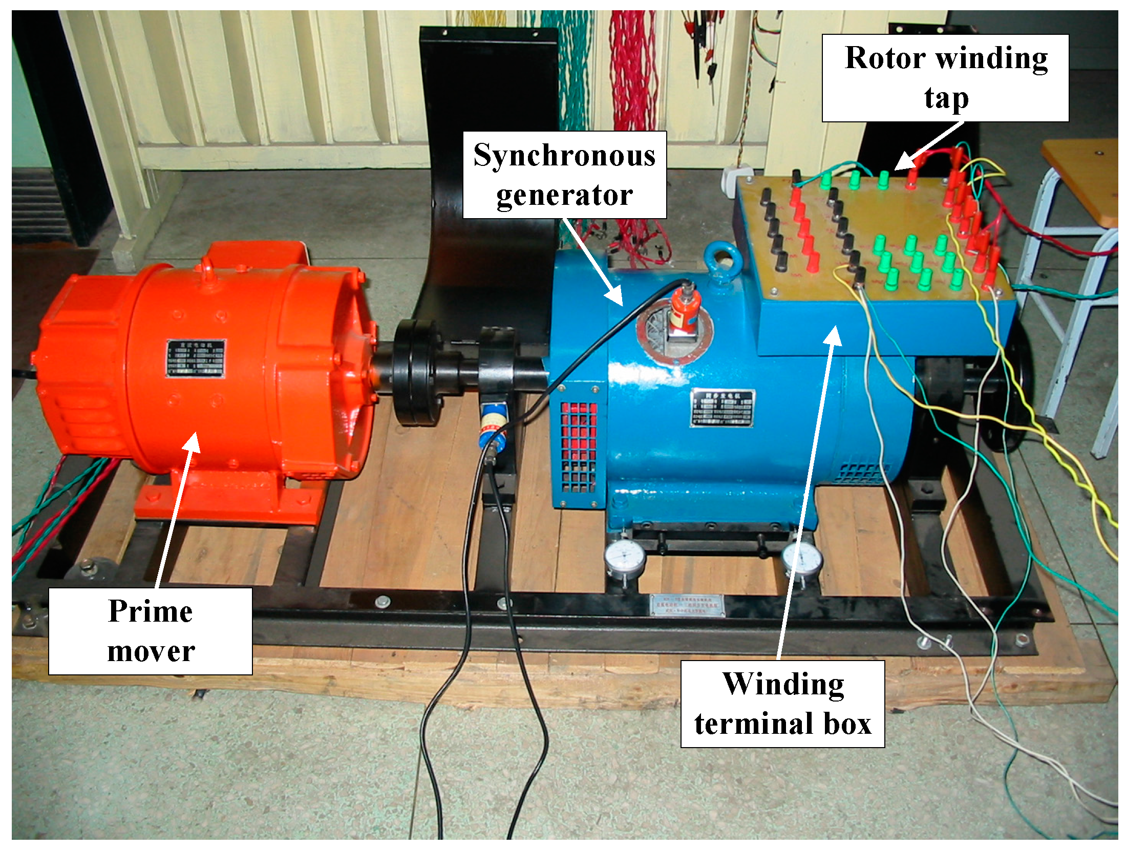
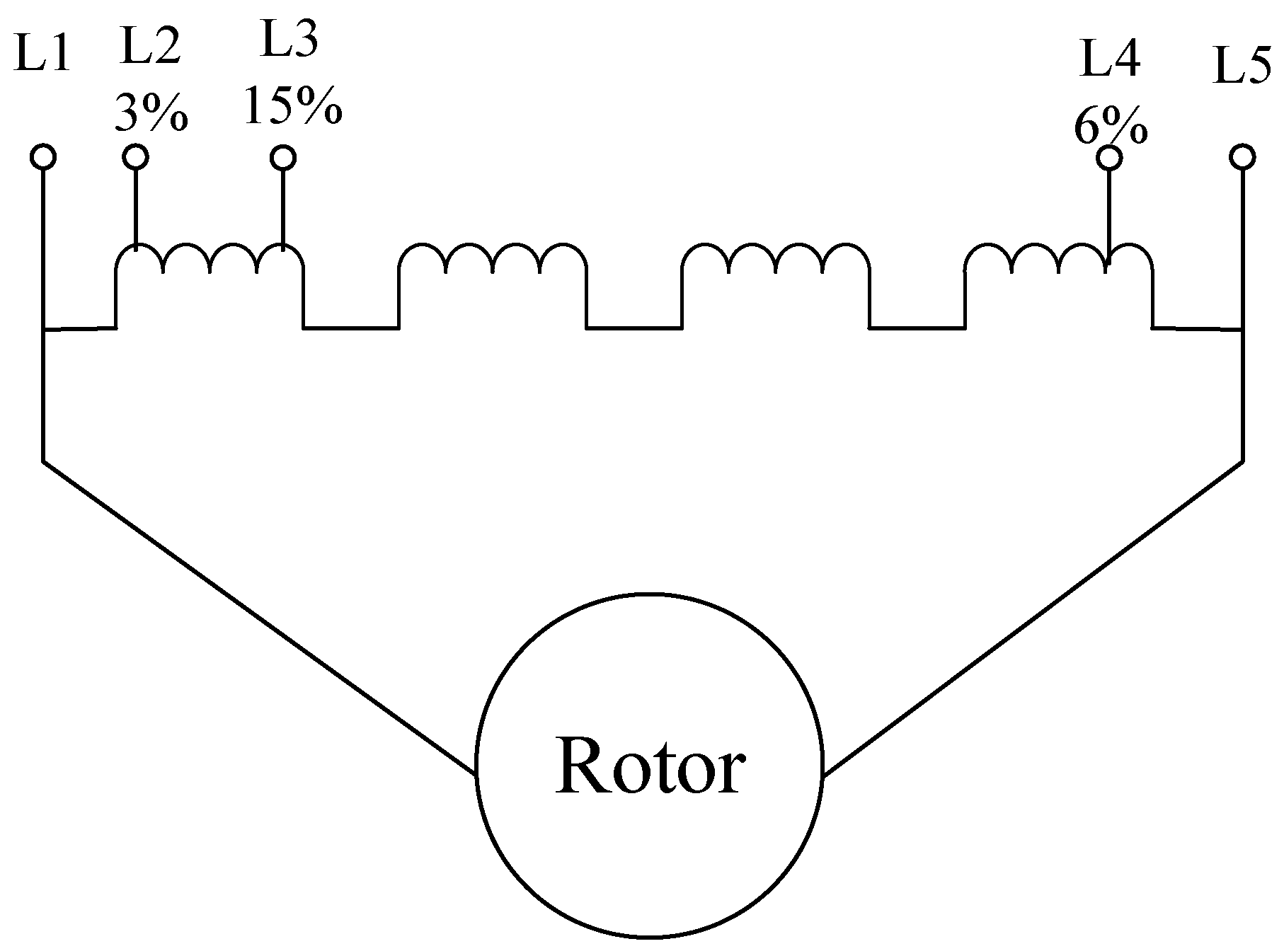
The inter-turn short circuit fault of the synchronous generator was simulated in a related experiment. The synchronous generator parameters are listed in Table 1. The generator experiment is shown in Figure 2. This is a special synchronous generator. It is designed to simulate inter-turn short circuit fault. As shown in Figure 2, the generator is equipped with winding terminal box. There are many taps on the stator windings and the rotor windings of synchronous generator. The schematic diagram of rotor winding connection is shown in Figure 3. The rotor windings have three taps. L2 tap accounts for 3% of the total turns. L3 and L4 account for 15% and 6%, respectively. It can simulate different cases of inter-turn short circuit fault by different combinations of the taps. To verify the accuracy of this method, the inter-turn short circuit ratio of the experiment is set at 3%–15%.
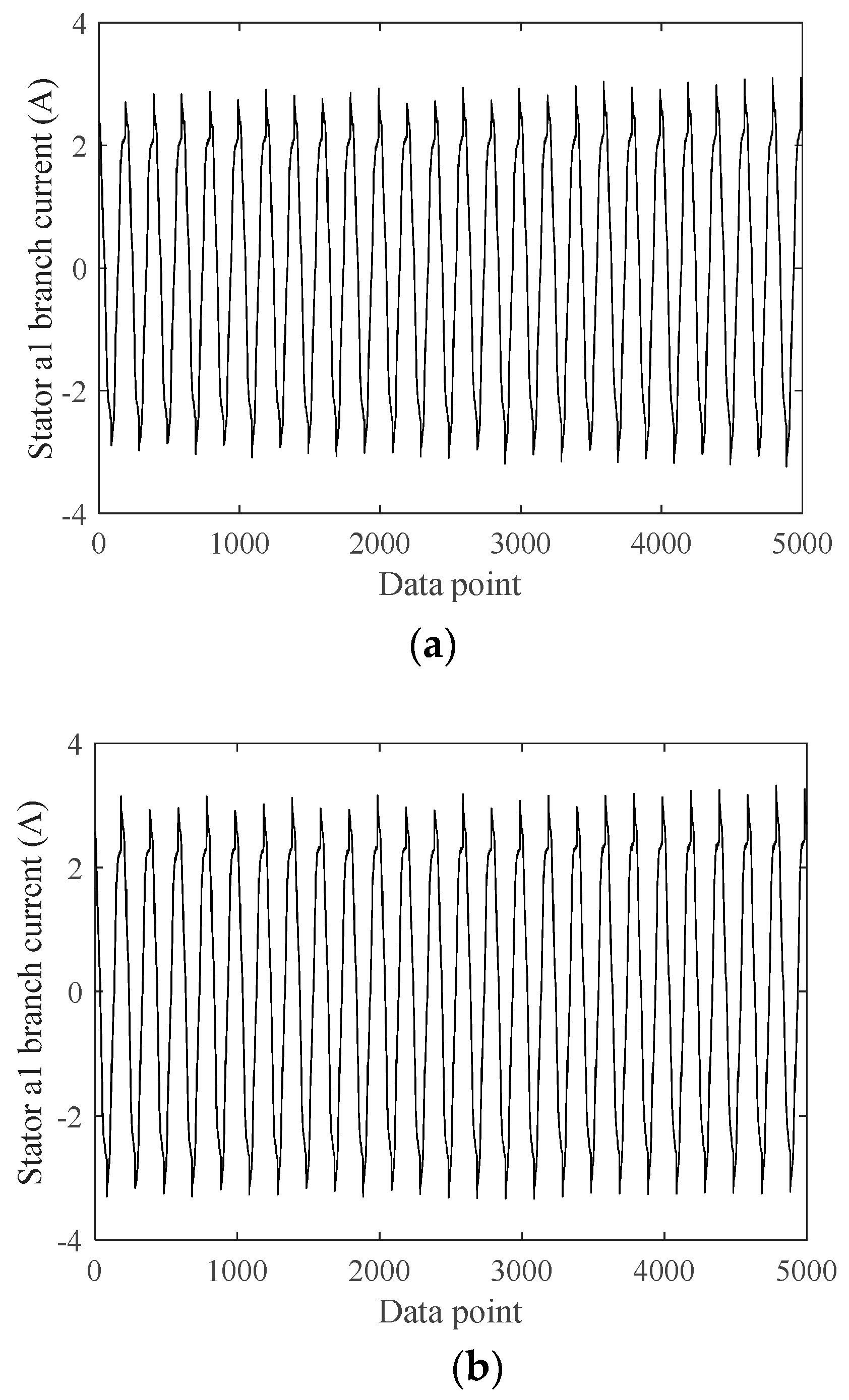
The experiment is as follows: Prime mover drives synchronous generator to synchro speed. The synchronous generator is connected to the grid while maintaining a certain operation mode. Adjusting the taps of rotor to simulate the generator inter-turn short circuit fault and collect relevant electrical parameters. Set the sampling frequency to 10 kHz. The stator branch current and stator branch voltage are collected under normal condition and fault condition. The stator a1 branch current waveform randomly taken out for several cycles is shown in Figure 4. Figure 4a is the stator branch current of the synchronous generator when the rotor winding is healthy. Figure 4b is the stator branching current at fault. According to Figure 4, the stator branch current contains interference. Traditional diagnostic methods cannot accurately diagnosis the law of current change and then identify the inter-turn short circuit fault. The Volterra kernel identification method is less affected by interference and can identify the inherent characteristics of nonlinear systems.
5. Stator Unbalance Current Volterra Kernel Identification
5.1. Volterra Three Order Kernels Identification
The voltage and current of the stator branches are taken as input and output of the Volterra series model, respectively. Unified voltage and current reference system can increase the accuracy of identification. Through recursive batch least squares method, the kernel function of nonlinear model is calculated and identified. According to the Volterra algorithm in Equation (3) and (4), Mk is set up, that is, the memory length of the three-order kernel function. According to the inter-turn short circuit fault of synchronous generator, the first-order time-domain kernel, the second-order time-domain kernel and the third-order time-domain kernel of the nonlinear transfer model are set to 20, 12 and 5, respectively. It can be known from Equation (9) that there are 20 first-order time domain kernels, 78 second-order time domain kernels, and 35 third-order time domain kernels. The results of three-order kernel functions are as follows.
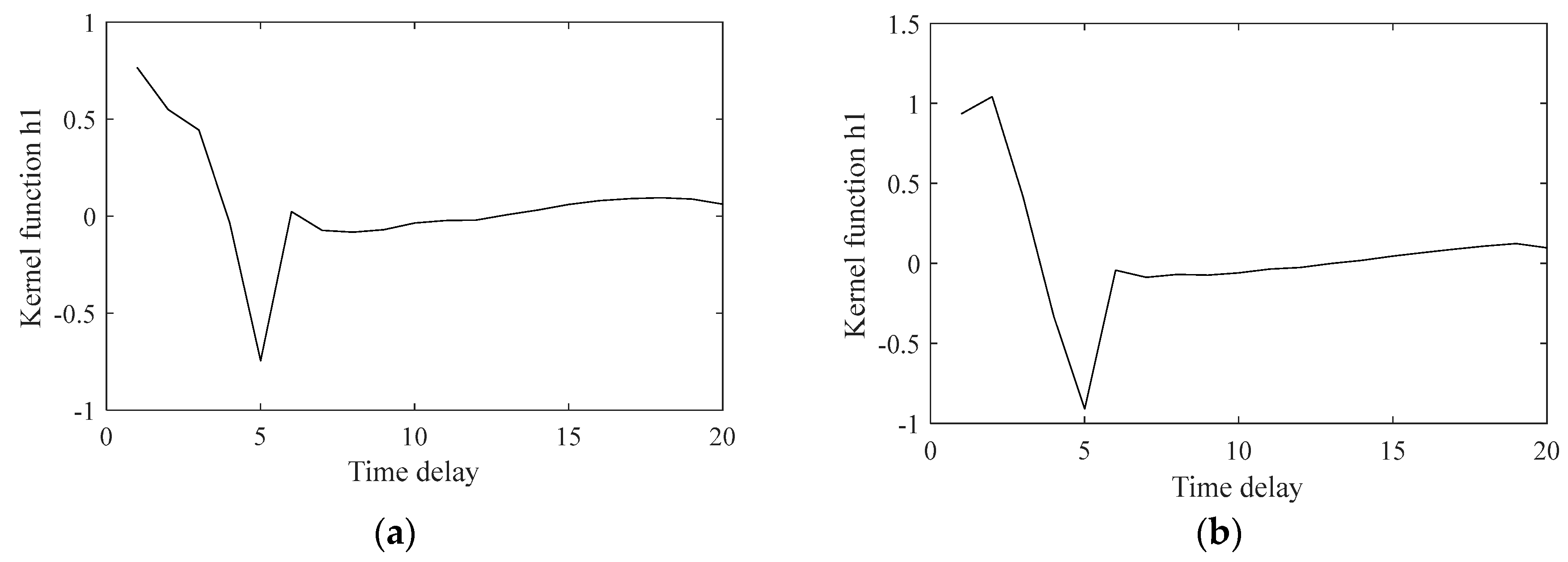
The first-order kernel identification results are shown in Figure 5. Figure 5a is the first-order kernel identification result when the winding is normal. Figure 5b is the first-order kernel identification result when the winding is short-circuited. In Figure 5, the value of the kernel function on the left side of the figure increases when the fault occurs. Some of the values change from <1 to >1.
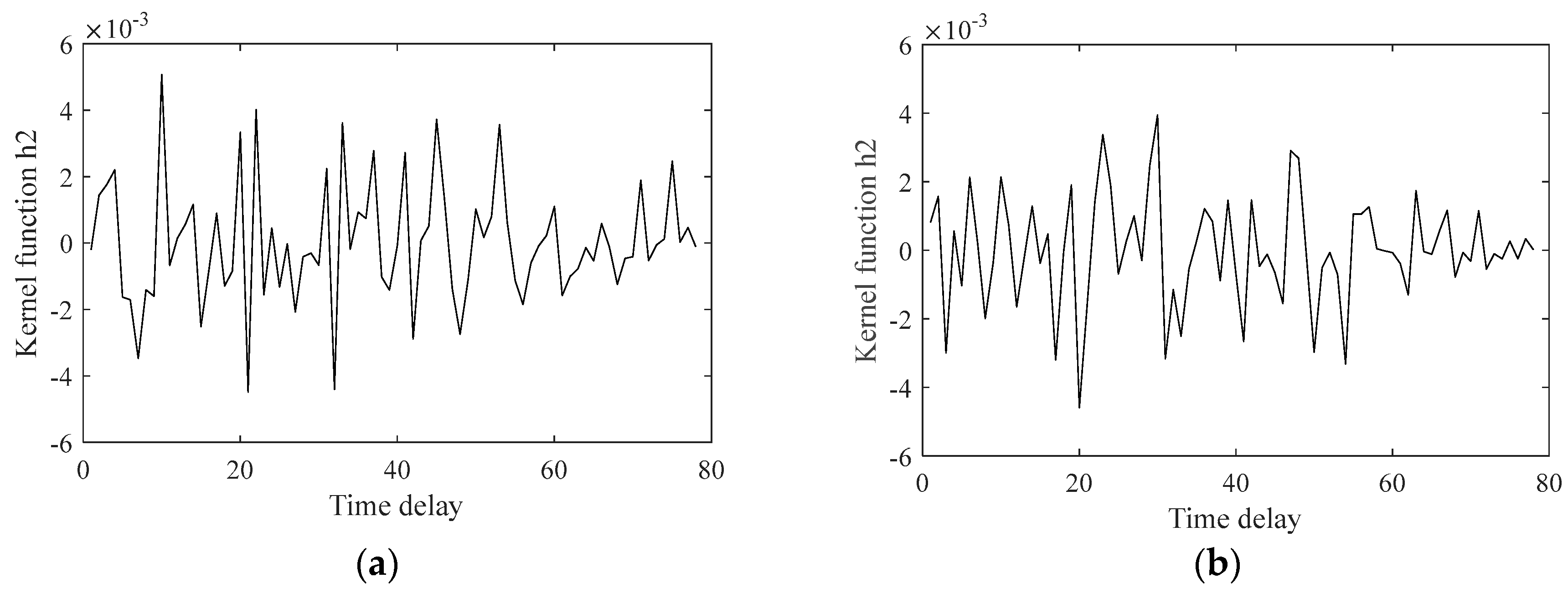
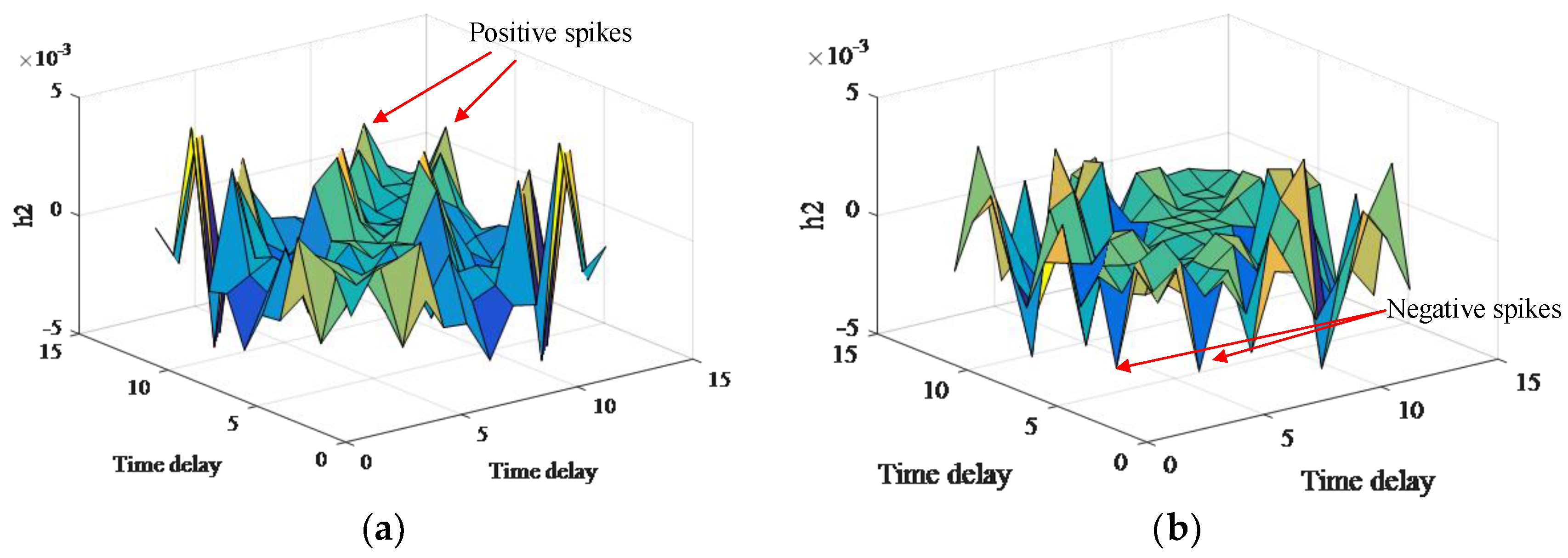
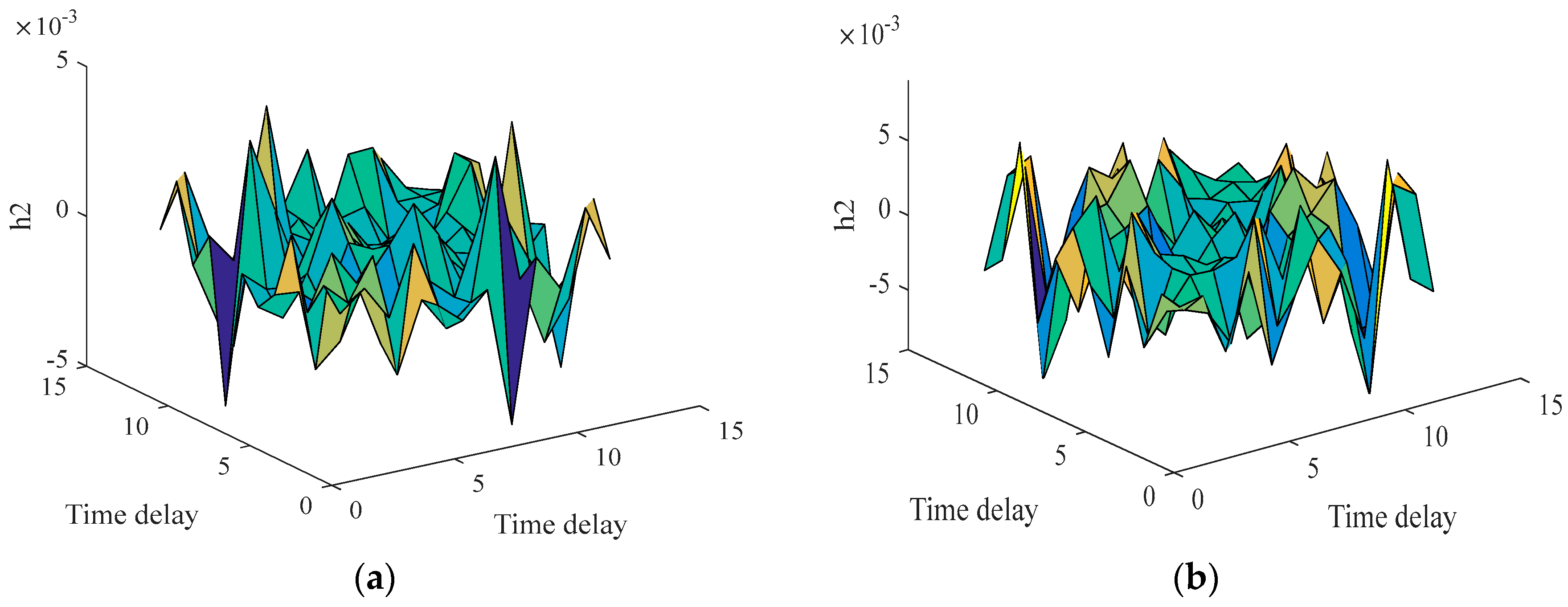
Figure 6 shows the results of the second-order kernel identification. Figure 6a is the second-order kernel identification result when the winding is normal. Figure 6b is the second-order kernel identification result when the winding is short-circuited. The second-order kernel waveform vibrates violently, and the range of vibration amplitude before and after fault is small. It is difficult to identify the inter-turn short circuit fault directly by analyzing the second-order Volterra kernel directly. Considering the characteristics of the second-order Volterra kernel, its three-dimensional surface is shown in Figure 7. Figure 7a shows the second-order kernel surface when the winding is normal. Figure 7b shows the second-order kernel surface when the winding is short-circuited. It can be seen that there are more positive peaks in the surface under normal condition of rotor winding. When inter-turn short circuit fault occurs, there are more negative peaks in the surface. It is possible to diagnosis the inter-turn short circuit based on this difference.
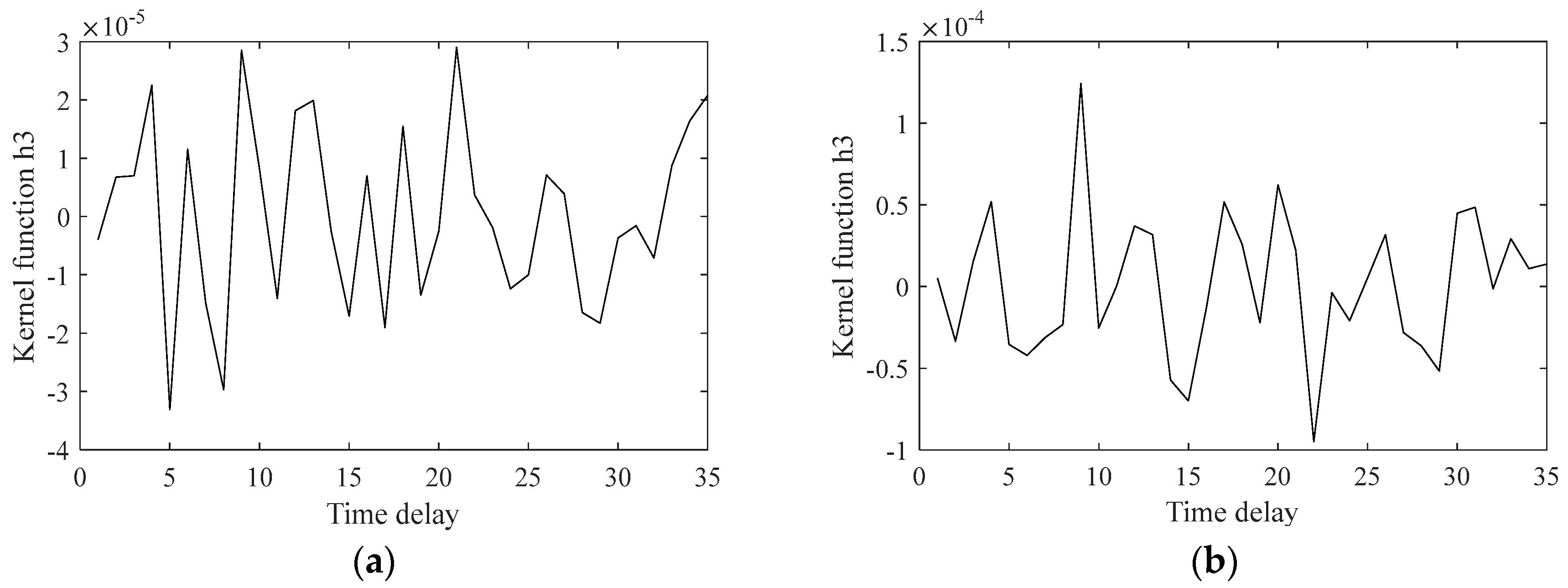
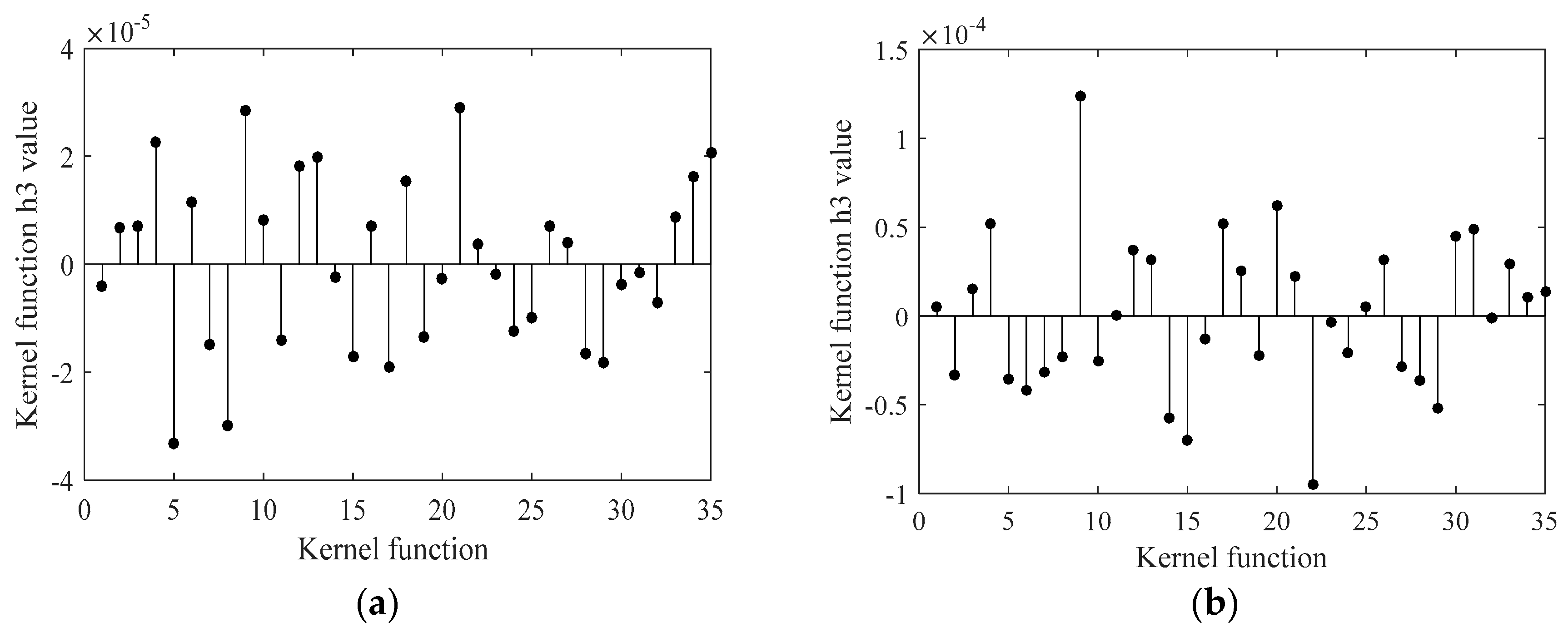
Figure 8 presents results of the third-order kernel function. Figure 8a is the third-order kernel identification result when the winding is normal. Figure 8b is the third-order kernel identification result when the winding is short-circuited. In Figure 8, it can be clearly seen that the amplitude ranges of the third-order kernel changes after fault. Under normal conditions, the third-order kernel change range is ±3 × 10⁻⁵. When inter-turn short circuit fault occurs, its amplitude range is ±1.3 × 10⁻⁴.
5.2. Volterra Kernel Identification Accuracy
The nonlinear model of stator branch voltage and stator branch current can be calculated forward to obtain kernel functions. The accuracy of the kernel function value reflects the accuracy of the identification of the nonlinear system. Substituting the kernel function into Equation (5) can obtain the faulty stator branch current estimated by the identification system. The result of comparison with the original fault current is shown in Figure 9. The black line is the original fault current, and the red line is the estimated current generated by the time domain kernel calculation. Figure 9 shows that the amplitude and phase of the current generated by Volterra series correspond well to the original fault current.
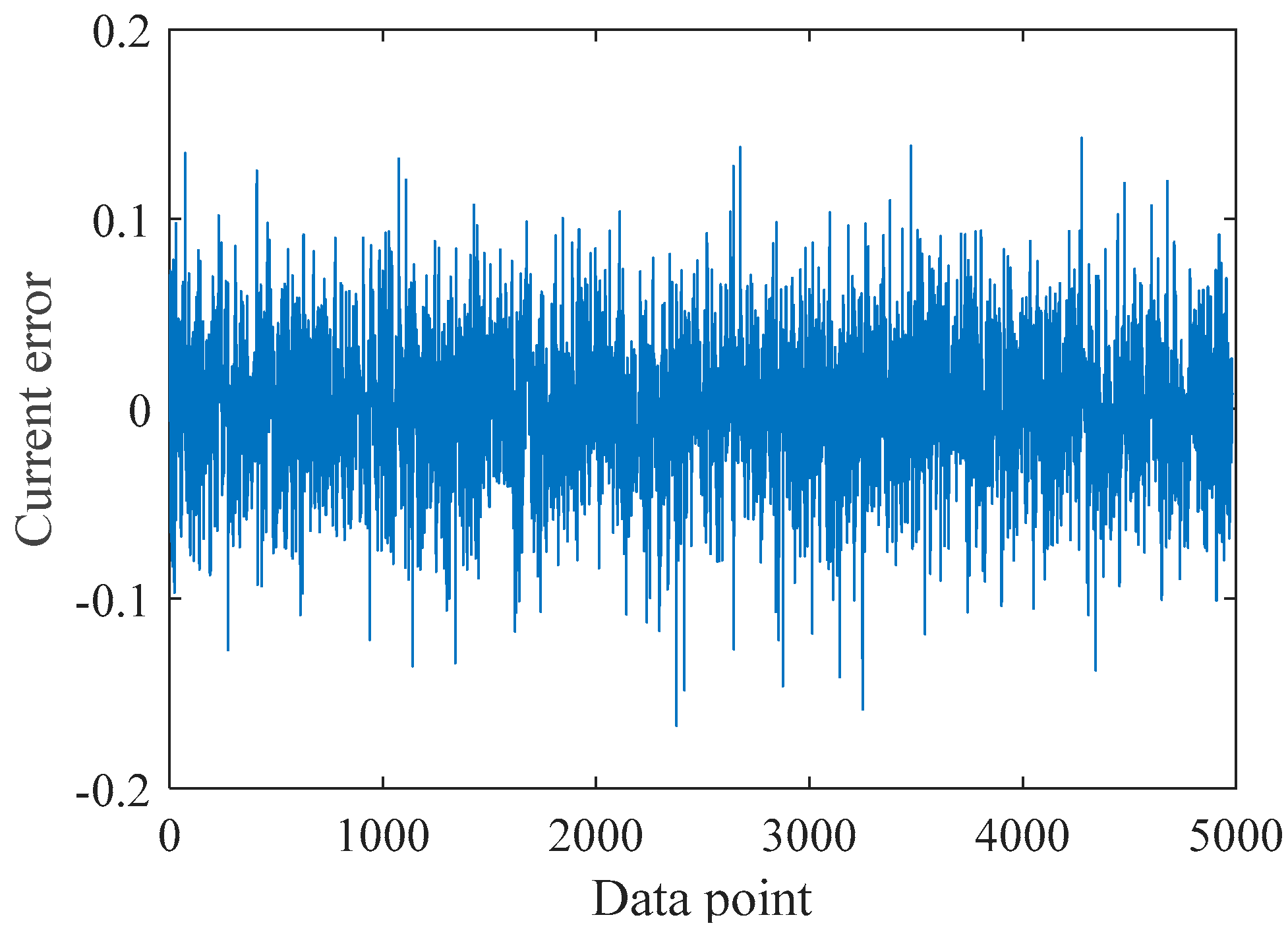
Figure 10 is the mean square error of the fitting current, which is very small compared with the original stator branch current. The identified mean square error less than 0.1 A is basically negligible. Therefore, the identification method based on Volterra kernel function has better reducibility to fault current, and its kernel function value has high accuracy.
5.3. The Absolute Mean of Volterra Kernel
Another set of experimental data was taken to further verify the correctness of the method. For convenience, the data used in the above are the first group and the new data are second group. Although the fault can be identified by the Volterra kernel function graph, to reflect the result of kernel identification more clearly and increase the stability of kernel identification, the absolute mean of Volterra kernel is proposed in this paper. The formula of absolute mean of Volterra kernel is
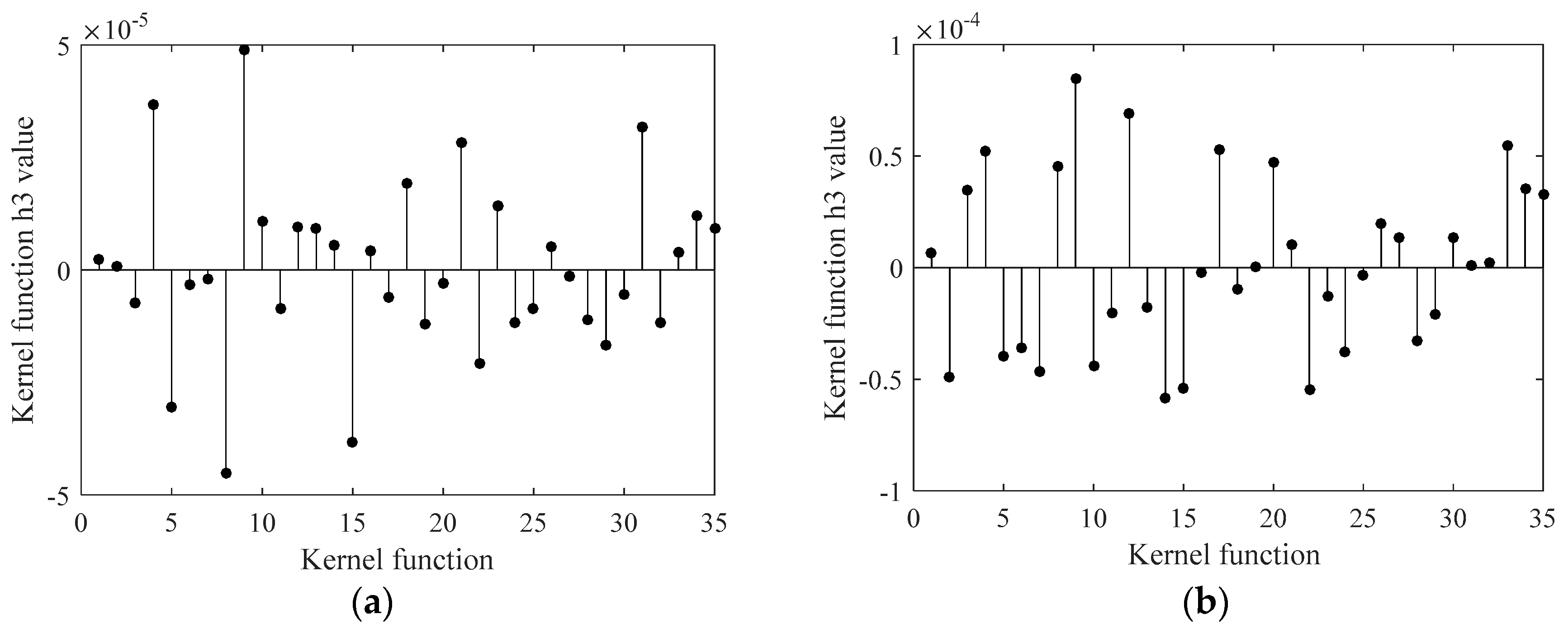
Take the third-order kernel function as an example to calculate absolute mean of Volterra kernel. Figure 11 shows third-order kernel function of the first group after discretization. Figure 11a is discretization result of three-order kernel of the first group when the winding is normal. Figure 11b presents the discretization result of three-order kernel of the first group when the winding is short-circuited. The third-order kernel function of the first group after discretization is shown in Figure 12. Figure 12a is the discretization result of three-order kernel of the second group when the winding is normal. Figure 12b presents the discretization result of three-order kernel of the second group when the winding is short-circuited. Substitute the data in Figure 11 and Figure 12 into Equation (18) to calculate absolute mean of third-order Volterra kernel. Similarly, the absolute mean of first- and second-order kernels can be calculated. The calculation results are listed in Table 2 and Table 3.
Table 2 lists absolute mean of all order kernels under normal conditions. Table 3 presents absolute mean of all order kernels under fault conditions. Comparing Table 2 and Table 3, it is concluded that the stability of Volterra kernel can be improved by calculation of absolute mean. In different cases, each absolute mean of kernel maintains its own stability. The absolute mean of first-order kernel is maintained at around 0.17, when the winding is normal. The absolute mean of third-order kernel is maintained at around 1.3 × 10⁻⁵. When the inter-turn short circuit fault occurs, the absolute mean of third-order kernel and first-order will increase. The absolute mean of first-order kernel value increase to about 0.25. The absolute mean of third-order kernel value increases to about 3.2 × 10⁻⁵. Based on this increase, inter-turn short circuit can be diagnosed. According to more experimental data, the third-order kernel gradually increases with the increase of short circuit percentage. Considering the error of measurement and calculation, it can be considered that the inter-turn short circuit fault occurs when the third-order kernel increases by more than 30%. Under this experiment condition, the threshold for diagnosis normal or fault is 1.8 × 10⁻⁵.
It is worth noting that the absolute mean of second-order kernel value cannot reflect inter-turn short circuit fault. This is because the absolute mean value is calculated from two-dimensional data. The second-order kernel needs to diagnose faults from 3D surfaces. The second-order kernel function surface of second group is shown in Figure 13. In Figure 13a, there are more positive peaks on the surface, while there are more negative spikes in Figure 13b. The variation rule of the second-order kernel is consistent with the conclusion in Section 5.1.
6. Conclusions
In this paper, the diagnosis method of inter-turn short circuit of synchronous-generator rotor winding based on Volterra kernel identification is proposed. Firstly, the feasibility of the stator unbalanced current as the characteristic quantity of the fault is analyzed. Secondly, the nonlinear Volterra model with stator branch voltage and current as input and output is built. Finally, the kernel function of the fault generator is identified by using the experiment data and the correctness of this method is verified. The main conclusions are as follows:
(1) The Volterra series model can be used to describe nonlinear problems in synchronous generators. The Volterra time-domain kernel of the nonlinear model of related electric quantity will change when the synchronous generator has the inter-turn short circuit fault. The fault can be diagnosed by analyzing the change of Volterra kernel characteristics.
(2) After the inter-turn short circuit fault occurs, the absolute mean of first-order kernel and third-order increases. The third-order kernel increases with the increase of short circuit ratio. When the inter-turn short circuit fault ratio is small, it can be diagnosed by third-order kernel. The three-dimensional surface of the second-order kernel has more positive peaks in normal situation. When inter-turn short circuit fault occurs, there are more negative peaks on the surface. The three orders of the Volterra series can be used to diagnose the inter-turn short circuit fault. Therefore, this method improves the accuracy of fault diagnosis.
(3) For the same nonlinear Volterra model, the absolute mean of first-order kernel and third-order change within the respective value range. This method has strong anti-interference ability and good robustness.
To sum up, the proposed method is feasible for detecting inter-turn short circuit fault online. After diagnosing the inter-turn short circuit fault of synchronous generator, timely removing inter-turn short circuit fault could improve the reliability of the generator.
Author Contributions
L.W. and Y.L. initiated the idea of the diagnosis of inter-turn short circuit based on Volterra kernel identification; Y.L. implemented the experiment of inter-turn short circuit fault of synchronous generator; L.W., Y.L. and J.L. analyzed the data; L.W. wrote the calculation program; L.W. wrote the paper; and Y.L. and J.L. proofread the paper.
Funding
This research was funded by Fundamental Research Funds for the Central Universities (2017XS115).
Acknowledgments
Thanks to the experimental synchronous generator provided by Lanzhou electric Limited by Share Ltd. Thank North China Electric Power University (Baoding) for providing the laboratory.
Conflicts of Interest
The authors declare no conflict of interest.
References
- Zhang, G.; Wu, J.; Hao, L. Analysis on the amplitude and frequency characteristics of the rotor unbalanced magnetic pull of a multi-pole synchronous generator with inter-turn short circuit of field windings. Energies 2018, 11, 60. [Google Scholar] [CrossRef]
- Wu, Y.; Li, Y. Diagnosis of rotor winding interturn short-circuit in turbine generators using virtual power. IEEE Trans. Energy Convers. 2015, 30, 183–188. [Google Scholar]
- Hao, L.; Wu, J.; Zhou, Y. Theoretical analysis and calculation model of the electromagnetic torque of nonsalient-pole synchronous machines with interturn short circuit in field windings. IEEE Trans. Energy Convers. 2015, 30, 110–121. [Google Scholar] [CrossRef]
- Zhang, G.; Wu, J.; Hao, L. Fast calculation model and theoretical analysis of rotor unbalanced magnetic pull for inter-turn short circuit of field windings of non-salient pole generators. Energies 2017, 10, 732. [Google Scholar] [CrossRef]
- Li, Y.; Wang, H.; Wu, Y.; Dong, C. Field winding short circuit fault diagnosis on turbine generators based on the ac impedance test. Large Electr. Mach. Hydraul. Turbine 2017, 4, 10–14. [Google Scholar]
- Chen, Y.; Zhang, B. Minimization of the electromagnetic torque ripple caused by the coils inter-turn short circuit fault in dual-redundancy permanent magnet synchronous motors. Energies 2017, 10, 1798. [Google Scholar] [CrossRef]
- Chen, Y.; Chen, X.; Shen, Y. On-line detection of coil inter-turn short circuit faults in dual-redundancy permanent magnet synchronous motors. Energies 2018, 11, 662. [Google Scholar] [CrossRef]
- Wu, Y.; Ma, M.; Li, Y. A new detection coil capable of performing online diagnosis of excitation winding short-circuits in steam-turbine generators. IEEE Trans. Energy Convers. 2018, 33, 106–115. [Google Scholar]
- Maraaba, L.; Al-Hamouz, Z.; Abido, M. An efficient stator inter-turn fault diagnosis tool for induction motors. Energies 2018, 11, 653. [Google Scholar] [CrossRef]
- Wang, X.; Sun, Y.; Gui, L.; Wang, W. Reasonable simplification of the multi-loop model of the large hydro generators. Proc. CSEE 2007, 27, 63–67. [Google Scholar]
- Hao, L.; Sun, Y.; Qiu, A.; Wang, X. Steady-state mathematical modeling and simulation of inter-turn short circuit of field windings in synchronous machines. Autom. Electr. Power Syst. 2010, 34, 51–56. [Google Scholar]
- Xia, X.; Zhou, J.; Zhu, W.; Li, C. Status recognition of hydraulic turbine runner based on blind identification of Volterra series. Proc. CSEE 2014, 34, 3392–3396. [Google Scholar]
- Wang, H.; Zhang, X.; Shi, L.; Wang, K. Application of the Volterra kernel function method in feature extraction of bearing ball wear. Appl. Math. Mech. 2017, 38, 633–642. [Google Scholar]
- Zhao, H.; Du, Z.; Liu, X.; Wang, Q. An on-line identification method for rotor resistance of squirrel cage induction motors based on recursive least square method and model reference adaptive system. Proc. CSEE 2014, 34, 5386–5394. [Google Scholar]
- Urresty, J.; Riba, J.; Romeral, L. Application of the zero-sequence voltage component to detect stator winding inter-turn faults in PMSMs. Electr. Power Syst. Res. 2012, 89, 38–44. [Google Scholar] [CrossRef]
- Saavedra, H.; Urresty, J.; Riba, J.; Romeral, L. Detection of interturn faults in PMSMs with different winding configurations. Energy Convers. Manag. 2014, 79, 534–542. [Google Scholar] [CrossRef]
- Mercorelli, P. Parameters identification in a permanent magnet three-phase synchronous motor of a city-bus for an intelligent drive assistant. Int. J. Model. Identif. Control 2014, 21, 352–361. [Google Scholar] [CrossRef]
- Chen, L.; Mercorelli, P.; Liu, S. A kalman estimator for detecting repetitive disturbances. In Proceedings of the American Control Conference, Portland, OR, USA, 8–10 June 2005; Volume 3, pp. 1631–1636. [Google Scholar]
- Wang, Z.; Tian, C.; Zhu, Q.; Huang, M. Hourly solar radiation forecasting using a volterra-least squares support vector machine model combined with signal decomposition. Energies 2018, 11, 68. [Google Scholar] [CrossRef]
- Stepniak, G.; Kowalczyk, M.; Siuzdak, J. Volterra kernel estimation of white light LEDs in the time domain. Sensors 2018, 18, 1024. [Google Scholar] [CrossRef] [PubMed]
- Xu, S.; Li, Y.; Huang, T.; Chan, R. A sparse multiwavelet-based generalized laguerre–volterra model for identifying time-varying neural dynamics from spiking activities. Entropy 2017, 19, 425. [Google Scholar] [CrossRef]
- Cheng, C. Volterra Series Based Nonlinear System Identification and Its Application; Shanghai Jiao Tong University: Shanghai, China, 2015. [Google Scholar]
- Fakhouri, S.Y. Identification of the volterra kernels of nonlinear systems. IEE Proc. Part D Control Theory Appl. 1980, 127, 296–304. [Google Scholar] [CrossRef]
- Jiang, J. Volterra Series Identification Method Based on Quantum Particle Swarm Optimization and Its Application in Fault Diagnosis; Zhengzhou University: Zhengzhou, China, 2010. [Google Scholar]
- Tang, X.; Yao, K.; Liu, B.; Hu, W.; Gao, F. Long-term battery voltage, power, and surface temperature prediction using a model-based extreme learning machine. Energies 2018, 11, 86. [Google Scholar] [CrossRef]
- Wang, X.; Xu, J.; Zhao, Y. Wavelet based denoising for the estimation of the state of charge for lithium-ion batteries. Energies 2018, 11, 1144. [Google Scholar] [CrossRef]
- Sun, Y.; Hao, L.; Wang, X. Calculation of the multi-loop inductances for inter-turn in non-salient pole synchronous short circuits of field windings machines. Autom. Electr. Power Syst. 2010, 34, 55–60. [Google Scholar]
- Hao, L.; Sun, Y.; Qiu, A.; Wang, X. The steady-state fault characteristics of a large hydro-generator with inter-turn short circuit of field windings. Autom. Electr. Power Syst. 2011, 35, 40–45. [Google Scholar]
Figure 1.
Rotor coordinates of synchronous generator.

Figure 2.
Inter-turn short circuit experiment.

Figure 3.
Rotor winding connection of the experimental generator.

Figure 4.
Stator a1 branch current of the experimental generator: (a) normal waveform; and (b) fault waveform.
Figure 4.
Stator a1 branch current of the experimental generator: (a) normal waveform; and (b) fault waveform.

Figure 5.
The first-order kernel identification: (a) normal winding; and (b) inter-turn short circuit.
Figure 5.
The first-order kernel identification: (a) normal winding; and (b) inter-turn short circuit.

Figure 6.
The second-order kernel identification: (a) normal winding; and (b) inter-turn short circuit.
Figure 6.
The second-order kernel identification: (a) normal winding; and (b) inter-turn short circuit.

Figure 7.
Second-order kernel function surface: (a) normal winding; and (b) inter-turn short circuit.
Figure 7.
Second-order kernel function surface: (a) normal winding; and (b) inter-turn short circuit.

Figure 8.
The third-order kernel identification: (a) normal winding; and (b) inter-turn short circuit.
Figure 8.
The third-order kernel identification: (a) normal winding; and (b) inter-turn short circuit.

Figure 9.
Comparison between identification current and actual current.

Figure 10.
Model identification prediction error.

Figure 11.
The first group of three-order kernel discretization: (a) normal winding; and (b) inter-turn short circuit.
Figure 11.
The first group of three-order kernel discretization: (a) normal winding; and (b) inter-turn short circuit.

Figure 12.
The second group of three-order kernel discretization: (a) normal winding; and (b) inter-turn short circuit.
Figure 12.
The second group of three-order kernel discretization: (a) normal winding; and (b) inter-turn short circuit.

Figure 13.
Second-order kernel function surface of second group: (a) normal winding; and (b) inter-turn short circuit.
Figure 13.
Second-order kernel function surface of second group: (a) normal winding; and (b) inter-turn short circuit.


Table 1.
Main technical data of synchronous generator.
| Model | SDF-9 |
|---|---|
| Rated Capacity/kVA | 7.5 |
| Rated power/kW | 6 |
| Rated voltage/V | 400 |
| Rated current/A | 3.8 |
| Excitation current/A | 1.4 |
| Rated rotating speed /rpm | 3000 |
| Power factor | 0.8 |
| Rated frequency/Hz | 50 |
| Winding connection | Y |
Table 2.
Absolute mean value of kernel function under normal winding condition.
| Experimental Group Number | First-Order | Second-Order | Third-Order |
|---|---|---|---|
| 1 | 0.1691 | 0.0014 | 1.3037 × 10⁻⁵ |
| 2 | 0.1746 | 0.00096 | 1.415 × 10⁻⁵ |
Table 3.
Absolute mean value of kernel function under inter-turn short circuit condition.
| Experimental Group Number | First-Order | Second-Order | Third-Order |
|---|---|---|---|
| 1 | 0.2291 | 0.0012 | 3.436 × 10⁻⁵ |
| 2 | 0.2748 | 0.0023 | 3.19 × 10⁻⁵ |
© 2018 by the authors. Licensee MDPI, Basel, Switzerland. This article is an open access article distributed under the terms and conditions of the Creative Commons Attribution (CC BY) license (http://creativecommons.org/licenses/by/4.0/).
Share and Cite
MDPI and ACS Style
Wang, L.; Li, Y.; Li, J. Diagnosis of Inter-Turn Short Circuit of Synchronous Generator Rotor Winding Based on Volterra Kernel Identification. Energies 2018, 11, 2524. https://doi.org/10.3390/en11102524
AMA Style
Wang L, Li Y, Li J. Diagnosis of Inter-Turn Short Circuit of Synchronous Generator Rotor Winding Based on Volterra Kernel Identification. Energies. 2018; 11(10):2524. https://doi.org/10.3390/en11102524
Chicago/Turabian StyleWang, Luo, Yonggang Li, and Junqing Li. 2018. "Diagnosis of Inter-Turn Short Circuit of Synchronous Generator Rotor Winding Based on Volterra Kernel Identification" Energies 11, no. 10: 2524. https://doi.org/10.3390/en11102524
Note that from the first issue of 2016, this journal uses article numbers instead of page numbers. See further details here.