Numerical Study on Heat Transfer Characteristics of the 36V Electronic Control Unit System for an Electric Bicycle


Department of Mechanical Engineering, Dong-A University, Busan 49315, Korea
*
Author to whom correspondence should be addressed.
Energies 2018, 11(10), 2506; https://doi.org/10.3390/en11102506
Submission received: 15 August 2018
/
Revised: 10 September 2018
/
Accepted: 18 September 2018
/
Published: 20 September 2018
Abstract
:The objective of this study was to numerically investigate the heat transfer characteristics of a 36V electronic control unit (ECU) system of an electric bicycle and to validate the experimental data. The temperatures of the ECU heatsink, seven metal-oxide-silicon field effect transistors (MOSFETs) and two capacitors of the 36V ECU system were numerically derived under variable operating conditions including power dissipation, thermal grease, ambient temperature and heatsink material, to analyze the heat transfer characteristics. When the thermal conductivity of the thermal grease increased from 0.01 W/m °C to 3.0 W/m° C, the temperatures of the seven MOSFETs and the two capacitors decreased by 51.245% and 3.58%, respectively. When the total power dissipation increased from 2.57 MW/m3 to 4.26 MW/m3, the temperatures of the ECU heatsink, seven MOSFETs and the two capacitors increased by 20.95%, 30.31% and 21.54%, respectively. Furthermore, increasing the ambient temperatures from 30 °C to 40 °C resulted in an increase in the temperatures of the ECU heatsink, MOSFET and capacitor by 24.75%, 9.93% and 22.04% respectively.. These numerically derived temperatures for the MOSFET and the ECU heatsink were validated with the experimental results within a range of 7.2% and 1.7%, respectively. This confirmed that the applied numerical model was valid.
1. Introduction
The transportation industry is in search of eco-friendly, green and renewable energy sources, and sustainable urban mobility due to increasing concerns over environmental protection, traffic and regulations on fossil fuel energy usage [1]. The concept of personal electric mobility such as scooters, bicycles and 3-wheeler neighborhood electric vehicles (NEVs) for small and medium range distances addresses the abovementioned key issues [2]. In comparison to larger vehicles, electric scooters and bicycles have a smaller volume, lighter weight, require less battery charging time and less parking spaces, which are promising features for short distance travel in areas with high traffic [3]. Thus, the market space for an electric bicycle is increasing rapidly. Particularly in 2011, 20% of total bicycle sales in The Netherlands were electric bicycles [4]. According to the records in 2011, nearly 310,000 electric bicycles were sold in Germany [5]. Researchers and engineers have recently studied the commercialization and performance characteristics of electric scooters and bicycles [6]. Weinert et al. analyzed the future of electric two-wheelers, electric bicycles and electric vehicles in China. They concluded that improvements in electric two-wheelers and battery technology, strong local regulatory support in the form of bans on gasoline-powered motorcycles and loose enforcement of the electric two-wheeler standards are the key factors that drive the market growth rate of these vehicles. In addition, they concluded that the strong demand for gasoline-powered motorcycles and bans on electric two-wheelers due to safety concerns in urban areas are the largest resisting forces that limit the market growth of electric two-wheelers [7]. Jones et al. analyzed the motivation, perceptions and experience of electric bicycle owners in Europe. They concluded that electric bicycles motivate people to cycle who would not ride a conventional bicycle and that they would change the traveling behaviors of the cycling public [8].
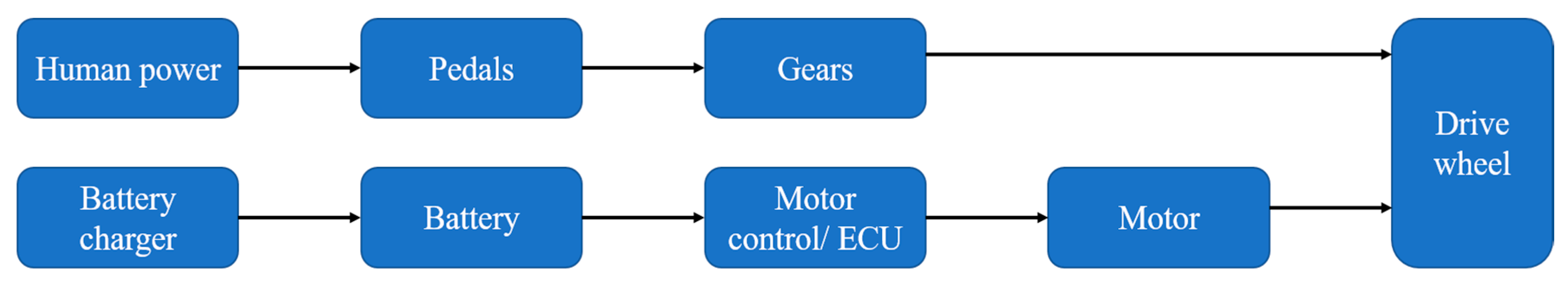
Many electric bicycles are hybrids and use human power as well as electrical power. An electrical powertrain consists of the battery charger, battery pack, electronic control unit (ECU), including the motor controller and the driving motor. Due to the rapid development of lithium-ion (Li-ion) battery technology, most electric bicycles are equipped with these batteries with a high-power density. Moreover, these batteries are sensitive to the environmental temperature and to the input/output current [9,10]. The ECU with the driving control motor unit is another important part of electric bicycles and is located between the battery and the motor (Figure 1). The ECU controls the motor speed, charging performances and several other functions, which controls the overall efficiency of the bicycle [11]. The capacitors in the ECU assist in maintaining the supply of a steady consistent current, resulting in a smooth and improved lifetime of the driving motor. This unit also supplies power to other electronic accessories such as the lights, horn and speed indicators. Thus, the performance of the ECU is crucial in determining the overall performance of the electric bicycle [12]. Jie Cing discussed the software and the hardware design of the electric bicycle ECU. He demonstrated how the ECU played an integral role in controlling the driving motor speed and its role in protecting the driving motor from over- and under-current from the battery [13].
Capacitors and metal-oxide-silicon field effect transistors (MOSFETs) are the main elements in the ECU, which generate heat during operation, due to the Joule effect. In addition, capacitors and MOSFETs also generate heat due to electrochemical reactions, dielectric losses and entropy changes [14]. This generation of self-heat and the ambient heat can affect the electrical and chemical properties of the capacitors [15]. Therefore, thermal management of the ECU is essential for the performance of the electric bicycle. However, only a limited number of studies have been conducted on the heat transfer characteristics of the ECU in an electric bicycle. One such study was based on the thermal performance of the battery with the application of a cell array guide for a 72V NEV [16]. Thus, the objective of this study is to numerically investigate the heat transfer characteristics of the 36V ECU system for an electric bicycle. The heat transfer characteristics were investigated under various operating conditions, including power dissipation, thermal grease, ambient temperatures and heatsink material. In addition, the temperatures of the same 36V ECU system were experimentally investigated and validated with the numerical data.
2. Numerical Method
2.1. Numerical Model
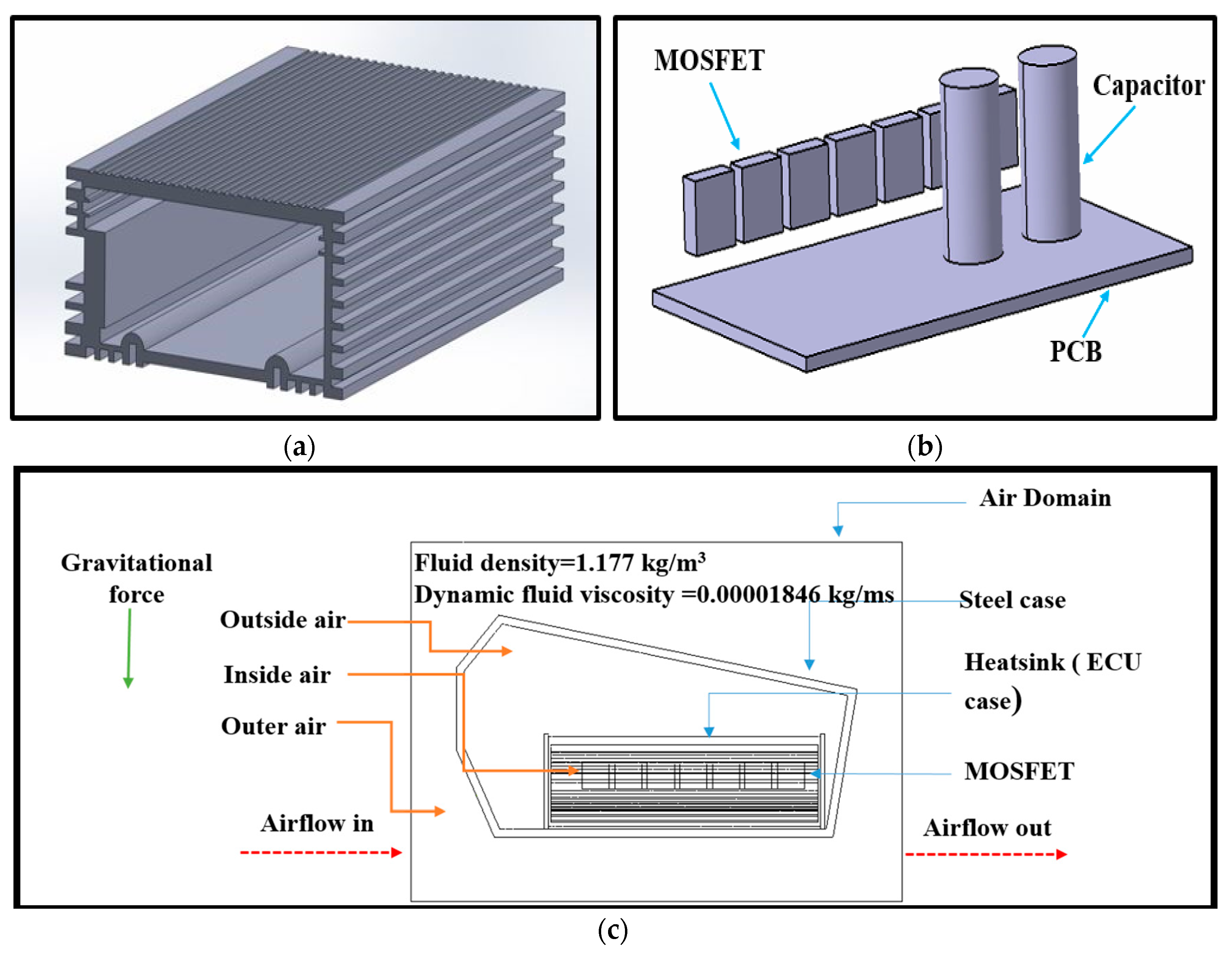
Figure 2 shows the computer-aided design (CAD) 36V ECU system which is 65.7 mm in width, 33 mm in height and 98.5 mm in length. As shown in Figure 2a, the 36V ECU outer case was originally designed with fins, and functions as the heatsink. Figure 2b shows a cross-section of the 36V ECU heatsink which has a maximum thickness of 4.5 mm and a minimum thickness of 2 mm. As shown in Figure 2c, the 36V ECU system is closed at either side with aluminum plates to protect the inner electronic elements from detrimental environmental conditions. Moreover, the 36V ECU system is placed in a closed steel chamber below the battery pack of the electric bicycle. Therefore, while riding the bicycle, airflow will occur from the front and gravitational forces will act in a direction vertical to the ECU. The 36V ECU system tested was also designed with two main components; an aluminum outer case which works as a heatsink, a printed circuit board with two CD288H capacitors and seven MOSFETs. Table 1 shows the designed 36V ECU heatsink specifications with dimensions.
2.2. Governing Equations
All the governing equations that were used in this study are listed as Equations (1)–(8). Equation (1) represents the flow continuity equation, where U is the vector of fluid velocity and ρ is fluid density. In this study, the fluid density is assumed as a constant throughout the domain. Therefore, the term of could be neglected and the Equation (2) can be derived [17].
The momentum equation is shown in Equation (3) where SM is the momentum source, τ is the molecular stress tensor, which is related to the strain rate and p is the static pressure. The terms . τ and SM could be neglected in Equation (3) due to the constant material properties and the fact that no forces act on the fluids inside the chamber, and Equation (4) can be derived [18].
Equation (5) shows the 3D thermal energy equation, where is the vector of the fluid velocity, kFis the thermal conductivity of the material (fluid), H is the specific static enthalpy, T∞ is the fluid temperature and SE is the energy source. The term τ: U is known as the viscous dissipation value and this term depends on the viscosity and the velocity of the fluid. Viscous dissipation could be neglected for a low viscous fluid such as air. Therefore, by neglecting the τ: U term in Equation (5), Equation (6) can be derived [18].
Equation (7) shows the conjugate heat transfer equation, which is used to calculate the solid domain heat transfer. In Equation (7), US is the velocity of the solid domain and kS is the thermal conductivity of the solid domain. In the present study, the solid domain velocity is equal to zero. Therefore, by neglecting the term of in Equations (7) and (8) can be derived [17].
2.3. Data Reduction
The Reynolds number can be calculated using Equation (9), where Re is the Reynolds number, ρ is the fluid density, is the dynamic fluid viscosity, u is the airflow velocity and L is the characteristic length [18].
The heat generation or power dissipation (PD) of the MOSFETs can be calculated using Equations (10)–(12), where PDRESISTIVE is the power dissipation by resistive loss, PDSW is the power dissipation by switching loss, I is the current, RDS(ON) is the static drain-source on-resistance, VIN is the input voltage of the MOSFET, VOUT is the output voltage of the MOSFET, CRSS is the small-signal reverse transfer capacitance, fSW is the switching frequency and IGATE is the MOSFET gate current.
The power dissipation of the capacitors can be calculated using Equations (13) and (14), where δ is the dissipation factor, f is the frequency and c is the capacitance of a capacitor [19].
Power dissipation = I2 × ESR
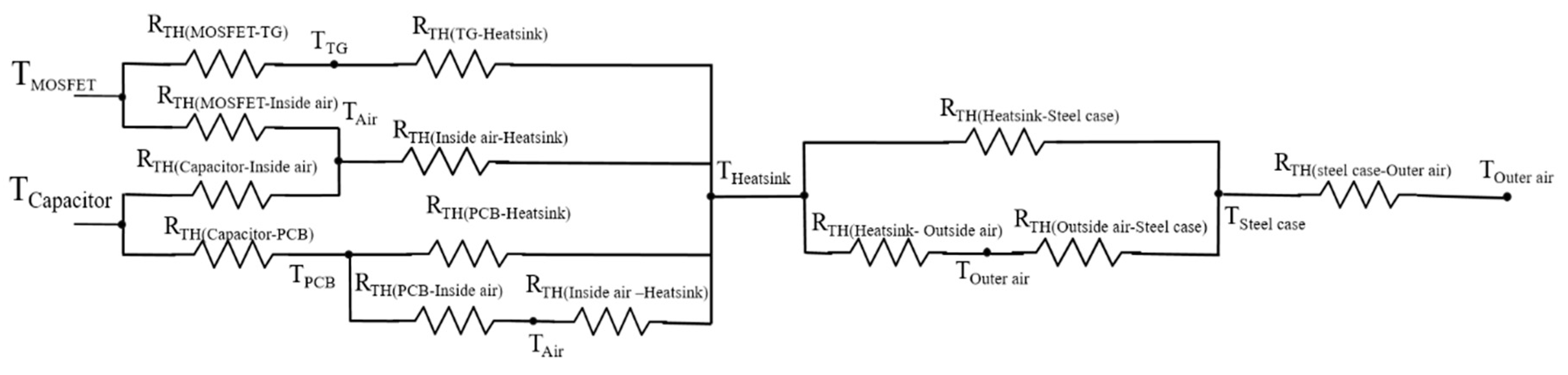
When thermal energy (Q) is applied to a substance, the temperature of the substance will change by a specific amount. As mentioned in Equation (15), the connection between the thermal energy and the temperature change (ΔT) depends on the material of the substance of mass (m) and the specific heat capacity (cp). Furthermore, heat flux (q’) is the amount of thermal energy emitted by a unit area [20]. As shown in Figure 3, the thermal resistance model was developed based on the geometrical locations of the ECU components to calculate the total thermal resistance of the system [21] and the thermal resistances of each component were calculated using Equation (17).
Thermal energy (Q) = m × cp × ΔT
Heat flux (q’) = Q/A
2.4. Numerical Method
ANSYS CFX 17.0 commercial software was used to conduct the numerical simulation in this study. The fluid density and the dynamic fluid viscosity were assumed to be 1.177 kg/m3 and 0.00001846 kg/ms, respectively. The distance a fluid particle travels in the boundary layer can be considered as the characteristic length [22]. The air velocity was assumed to be 0.01 m/s based on the location of the 36V ECU and the speed of the bicycle [23]. The Reynold number was calculated as 32.33 (<2300) and the air flow was assumed to be laminar flow. Moreover, the thermal conductivity and specific heat of the fluid and the solid domains were assumed to be independent of the temperature and the non-slip boundary condition for the fluid was applied at the fluid-solid interface [24].
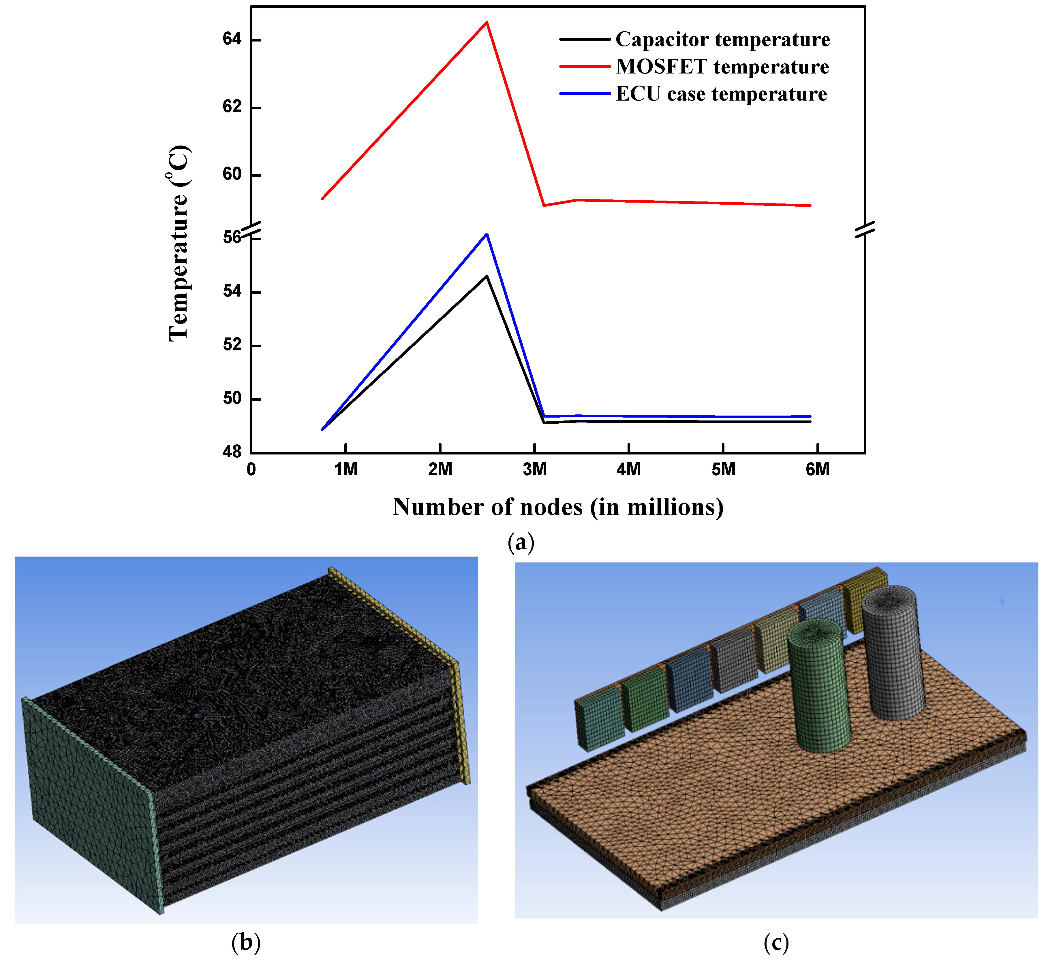
Figure 4 shows the meshing details for the tested 36V ECU system. In a numerical simulation, the grid independency was examined because meshing is an important factor that can affect the results. As shown in Figure 4a, the maximum temperatures of the tested ECU case, the MOSFETs and the capacitors did not vary more than 0.05 °C when the number of grids was increased, after reaching the grid number 3.1 × 10⁶. Hence, it was assumed that the grid number 3.1 × 10⁶ is suitable for conducting all numerical simulations. Figure 4b shows the meshing details for the tested 36V ECU system. The mesh consisted of 7,252,948 tetrahedrals, 2,367,783 wedges, 36,373 pyramids and 81,327 hexahedral elements. As shown in Figure 3c, the proximity and the curvature sizing functions were used to create fine mesh near the edges and the curves.
Table 2 shows the main components in the 36V ECU tested and the materials used in these components. Various ECU case materials were considered in an attempt to analyze the effect of the constituent materials. Based on the year-round temperature variation in South Korea, the ambient temperatures of the numerical simulations were varied as −20 °C, −10 °C, 0 °C, 20 °C, 25 °C, 30 °C and 40 °C to analyze the ambient temperature effect on the 36V ECU system [25]. Figure 5 shows the simplified electric circuit diagram of the 36V ECU system for an electric bicycle with reference to the original ECU electric circuit. The 36V ECU system controls three phase (U,V,W) brushless motor with a power output of 250 W. As shown in Figure 5, the main heat generating sources of the system considered are the MOSFETs and the capacitors. The theoretical power dissipation of two heat sources could be calculated by Equations (10)–(14) and the manufacturer’s datasheets for the SiHFZ34 MOSFET and the CD288H capacitor [26,27].
The power dissipation of the MOSFETs and the capacitors may change with the operating conditions. Therefore, the numerical simulations were repeated with a total ECU power dissipation values from 2.57 MW/m3 to 4.26 MW/m3 to analyze the thermal performances of the unit, capacitors and the MOSFETs. The gap between the MOSFET and the heatsink could increase the thermal resistance between these two parts of the 36V ECU system. Therefore, various thermal greases such as thermal pads, thermal gel and thermal filling were analyzed to decrease the thermal resistance between these two components and to analyze the effect of thermal grease on thermal performances of the 36V ECU system. The numerical simulations were conducted with different thermal conductivity values of thermal grease which are in the range of the actual thermal conductivity values of the thermal grease used in ECU systems [28]. All the applied conditions for these numerical simulations are indicated in Table 3.
3. Experimental Method
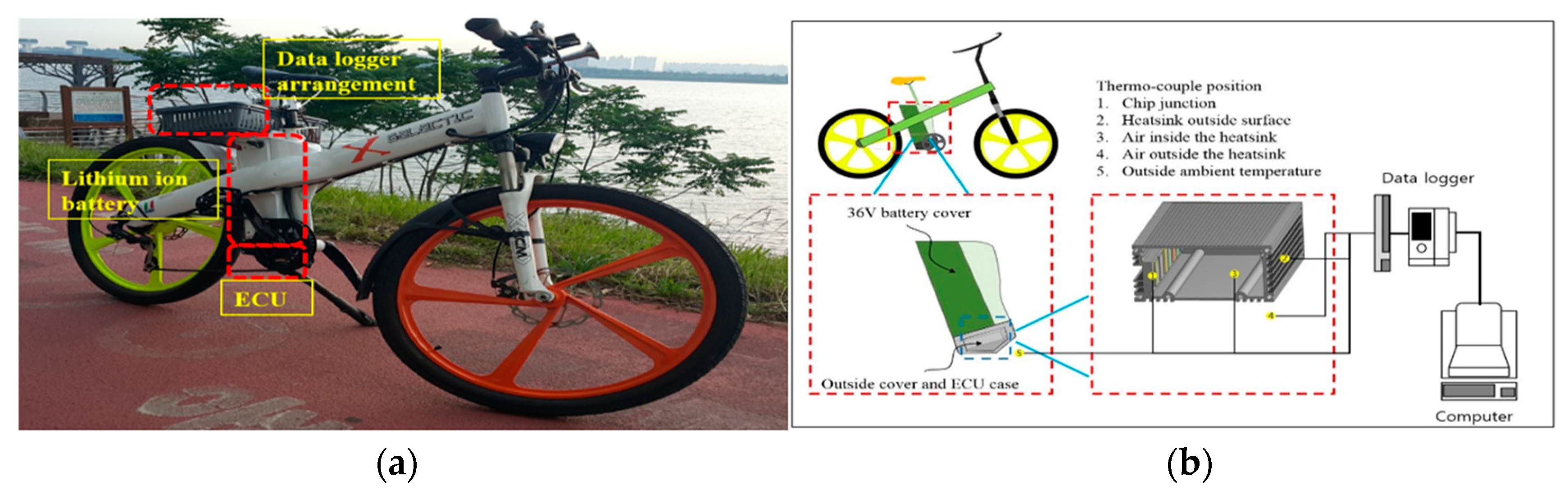
As shown in Figure 6a, the 36V ECU system was placed close to the battery pack to control the motion of the electric bicycle. Table 4 shows the specifications of the Li-ion battery. A battery with 36V of the nominal voltage and 10.4 Ah of nominal capacity was attached to the bicycle’s frame. Figure 6b shows a schematic diagram of the 36V ECU system of the experimental setup with the 36V Li-ion battery, 36V ECU, T-type thermocouples, data logger of the GRAPHTEC midi LOGGER GL820 and a computer for data processing. The 36V ECU system consisted of seven MOSFETs, two CD288H capacitors, a printed circuit board (PCB) and the ECU case. The MOSFETs, the capacitors and the PCB were located inside the case. This case, which is made of aluminum, serves as a protective case for the internal parts, as well as a heatsink. The attached heatsink design plays an important role in dissipating the generated heat from the MOSFETs and capacitors. The data logger, with an accuracy of ±0.1% for a reading of 0.5 °C, was used to measure and record the temperatures. A total of five T-type thermocouples were applied to measure the temperatures of the ambient air, the MOSFET junction, the ECU surface, inside air and the outside air of the ECU heatsink of the electric bicycle, respectively. Table 5 shows the test driving conditions for the city-drive mode case. The experiment was conducted with a 70 kg rider riding on a dry, concrete, and flat bicycle riding track located in Busan. The average velocity of the electric bicycle was set at 30 km/h with an elapsed time of 1500 s, since the velocity of the battery-powered electric bicycle is generally limited to this value for passenger safety and the stable performance of the battery. The ambient temperature for the comparison between the numerical result and the experimental result was fixed at 22 °C according to the average temperature of spring, autumn and summer, except for the winter in the Republic of South Korea [25].
4. Results and Discussion
4.1. Validation and Base Test
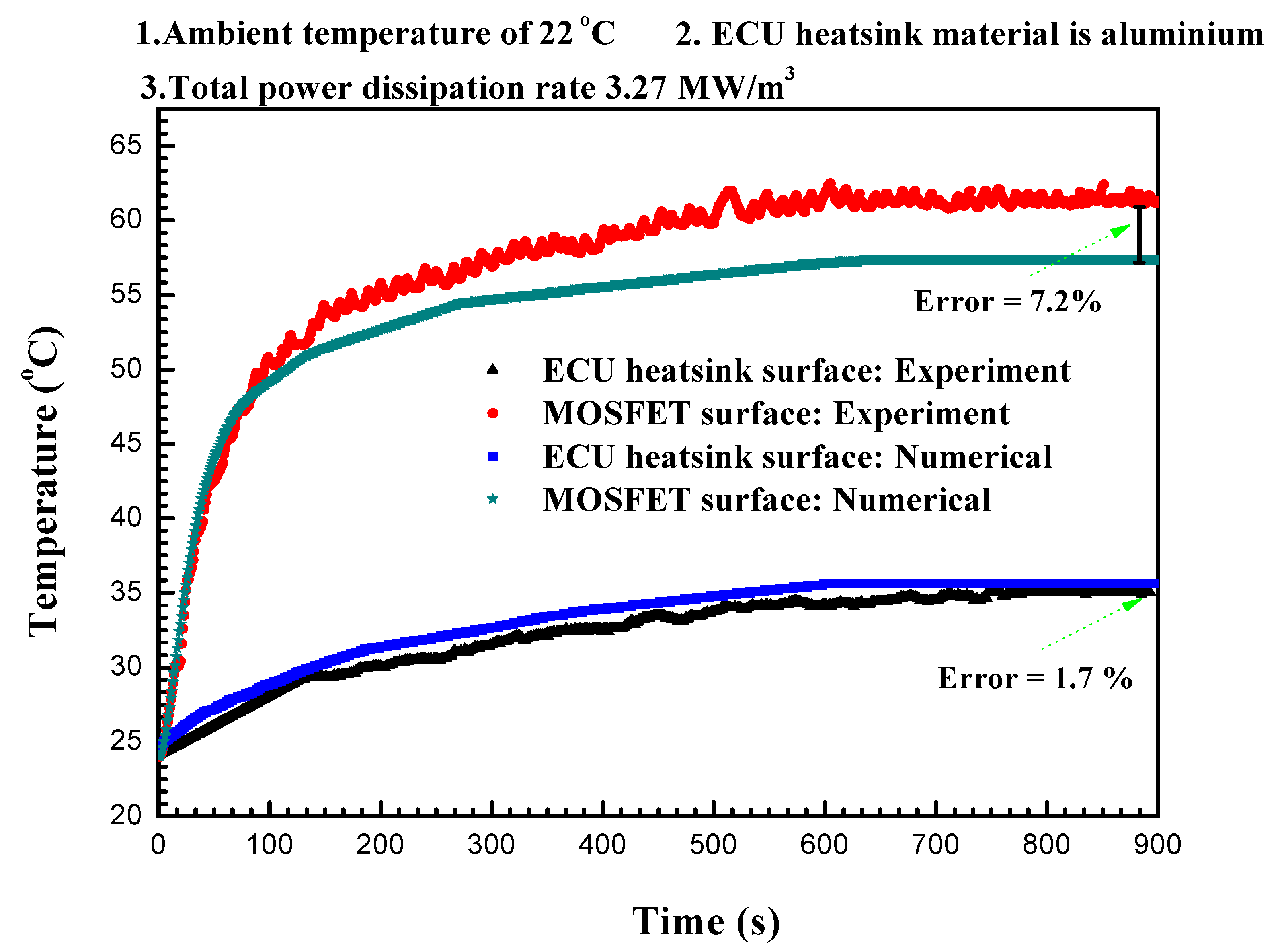
Figure 7 shows the experimental and numerical temperature results of the ECU heatsink for the 36V ECU system at a speed of 30 km/h and at an ambient temperature of 22 °C. The experimentally-obtained temperatures of the MOSFET and the ECU heatsink were 61.80 °C and 35.0 °C, respectively. The numerically derived temperatures of the MOSFET and ECU heatsink were 57.33 °C and 35.59 °C, respectively. The numerically-derived temperatures for the MOSFET and the ECU heatsink can be validated with the experimentally obtained temperatures within 7.2% and 1.7%, respectively. This indicates that the present numerical model is valid. Figure 7 also shows that the temperature increment trends of MOSFETS and ECU heatsink surface in experimental and numerical results are the same.
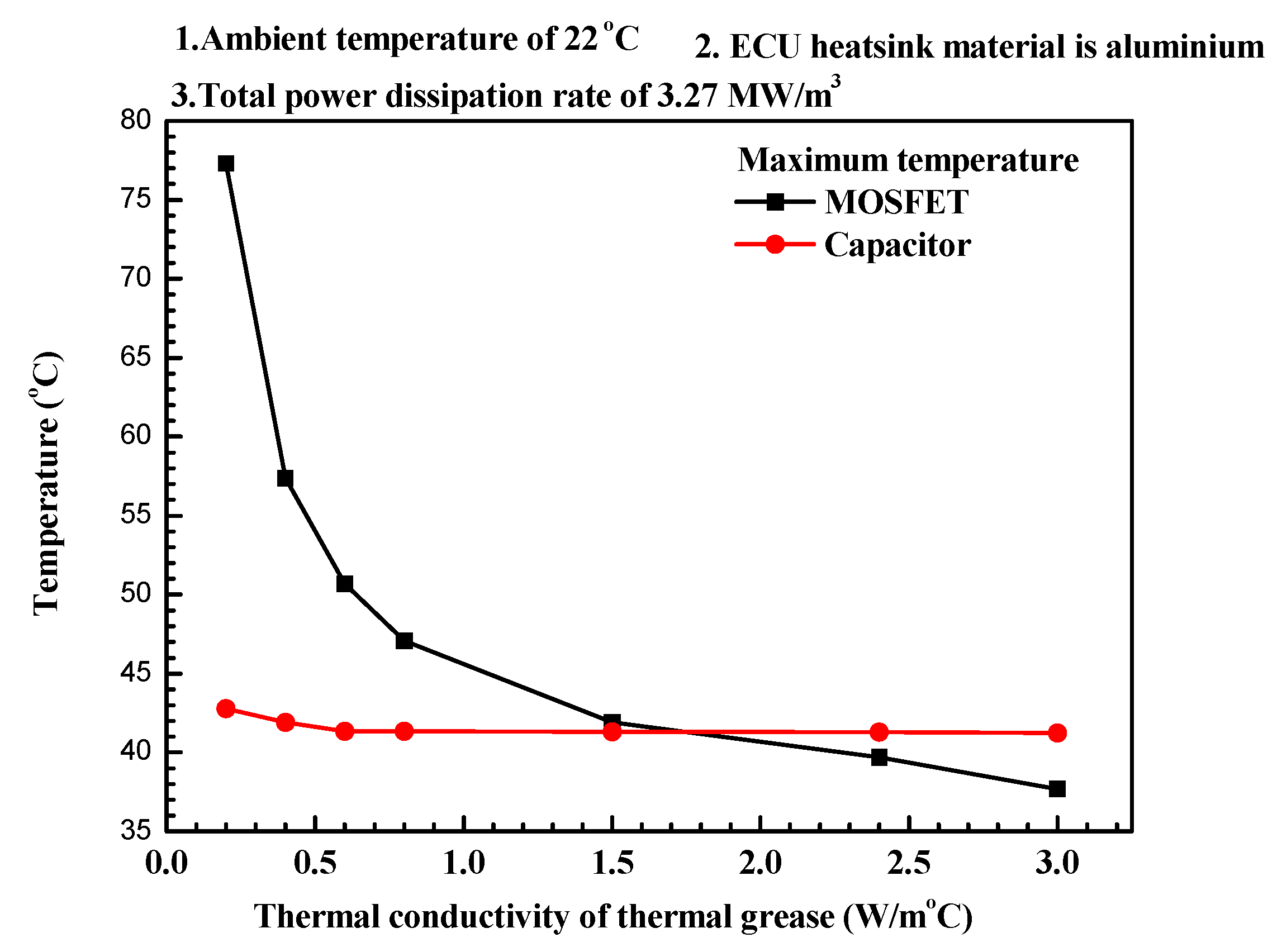
The MOSFET is attached to the ECU heatsink and microscopic imperfections on these transistors and the ECU heatsink surface can result in air gaps between the two components. These air gaps could lead to poor thermal conductivity, thereby reducing the heat transfer rate in the contact surface between the MOSFET and the heatsink. Thus, thermal grease with good thermal conductivity is applied to fill these air gaps and to increase the heat transfer rate [29]. Figure 8 shows the maximum temperatures of the seven MOSFETs and the two capacitors of the 36V ECU system with the thermal conductivity of the thermal grease. Thermal greases with thermal conductivities of 0.01 W/m °C and 3.0 W/m°C were used in this study. These thermal greases are commercially available, except for the thermal-physical properties [29]. When the conductivity of the thermal grease was 0.01 W/m °C, the temperatures of the MOSFET and the capacitors of the 36V ECU were 77.31 °C and 42.7 °C, respectively. Moreover, when the conductivity of the thermal grease was 3.0 W/m °C, the temperatures of the MOSFET and the capacitors were 37.7 °C and 41.25 °C, respectively. This indicates that an increase in the thermal conductivity of the thermal grease from 0.01 W/m °C to 3.0 W/m °C can decrease the temperatures of the MOSFET and capacitors by 51.24% and 3.58%, respectively. The temperature decrease of the MOSFET was more pronounced than that of the capacitors, possibly due to the direct contact of the MOSFET with the heatsink in the presence of thermal grease.
4.2. Temperature Characteristics
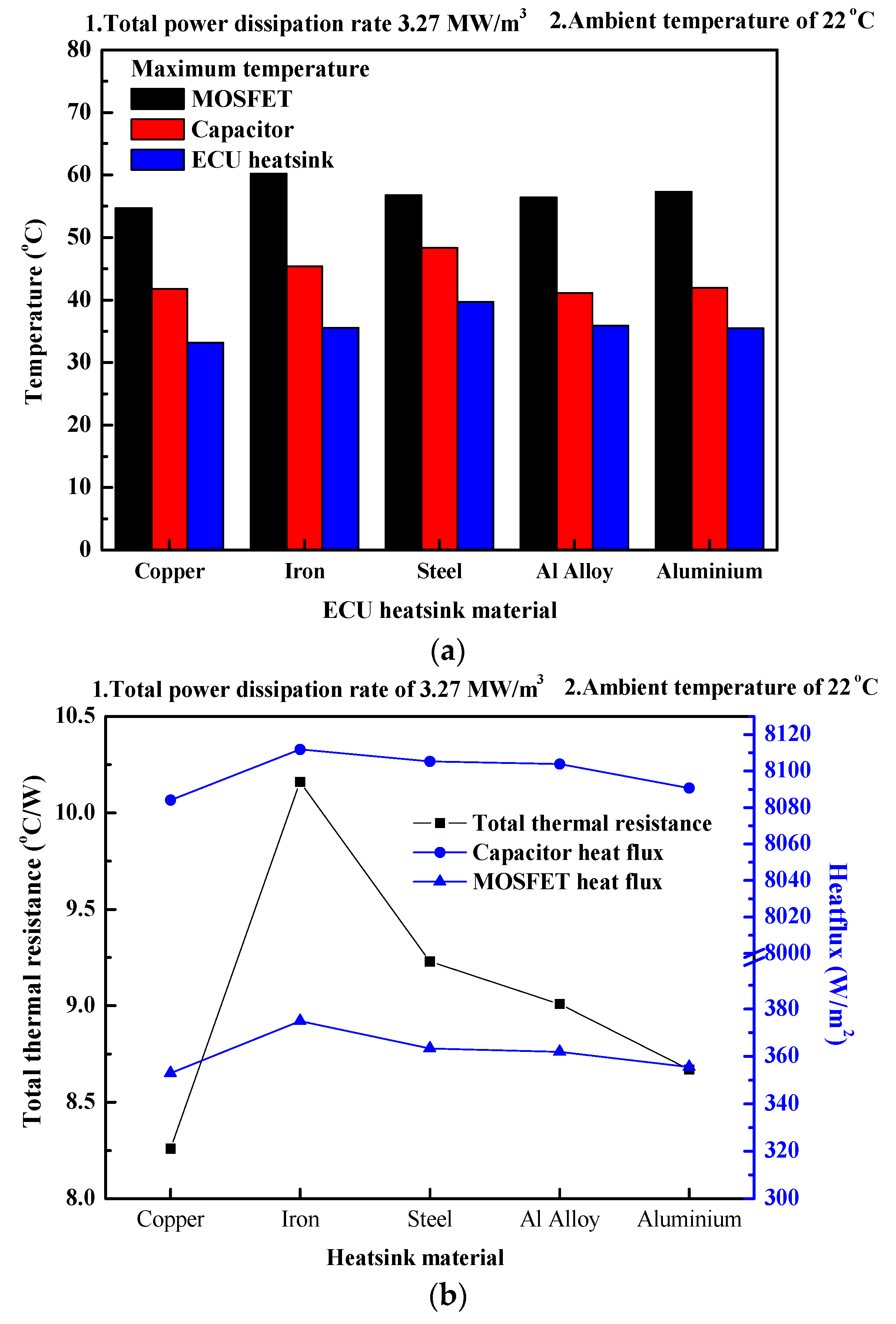
The ECU heatsink of the 36V ECU system is made of aluminum. Various materials with higher thermal conductivity and lower heat capacity were considered to enhance the heat transfer rate of the ECU heatsink [30]. Figure 9 shows the temperatures, thermal resistance and heat flux of the 36V heatsink ECU system with different ECU heatsink materials. In this study, copper, steel, aluminum alloy and aluminum were considered as the case materials for the ECU heatsink. Aluminum is widely used in heatsinks since it has a higher thermal conductivity and is lighter in weight than most metals. Steel and iron are heavier and less reliable than aluminum and are less preferred for use in heatsinks [31]. Aluminum alloy is made of 85% aluminum and 15% of copper manganese, silicon, tin and zinc [32]. The temperatures of the ECU heatsink, the MOSFET and the capacitor of the were 35.59 °C, 57.33 °C and 41.92 °C, respectively for aluminum and 33.16 °C, 54.27 °C and 41.78 °C, respectively for copper. These values show that the temperatures of the ECU heatsink, MOSFETs and the capacitors with a copper heatsink were lower by 6.82%, 5.33%, 0.33% in comparison to that with aluminum. In comparison to aluminum, cases with iron resulted in an increase in the temperatures of the ECU heatsink, MOSFET and the capacitor by 11.60%, 5.02% and 8.25%, respectively. This could be due to the lower thermal conductivity and higher thermal resistance of iron in comparison to aluminum [33]. The temperatures of the ECU heatsink, MOSFET and capacitor with aluminum alloy were 35.49 °C, 56.39 °C and 41.15 °C, respectively, which are lower by 0.28%, 1.64%, and 1.84%, respectively than that of with aluminum. However, aluminum alloy is not a common material that is used for ECU heatsinks for electric bicycles [34]. In general, the temperatures of the ECU heatsink, MOSFET and the capacitors were the lowest when copper was used. This could possibly be due to the low thermal resistance and low specific heat of copper [35]. The heat flux indicates that the heat flow intensity or heat flow density per unit area per unit time [36]. Figure 9b shows the variations of total thermal resistance and heat flux of the 36V ECU system with different 36V ECU heatsink materials. The heatsink with copper showed the lowest heat flux for the heatsink, capacitor and MOSFET, because copper has the lowest temperature difference with compared to the existing aluminum heatsink. The existing aluminum heatsink exhibited 8090.66 W/m2 heat flux for the MOSFET and 355.56 W/m2 for the capacitor. In comparison to the existing aluminum heatsink, the copper heatsink showed 0.081%, and 0.74% lower heat flux for the MOSFET and capacitor, respectively. Steel is composed of iron and carbon. Therefore, steel has an increased heat capacity and a lower density than iron [37]. In comparison to the existing heatsink, the heat flux of the MOSFET and the capacitor for the 36V ECU system was increased by 0.26% and 0.05%, respectively with an iron heatsink and by 0.18% and 0.02%, respectively with a steel heatsink. This is because the thermal conductivities of iron and steel are lower than that of aluminum [38]. Low purity in the aluminum alloy results from the manufacturing process which causes the poor thermal conductivity and increases the thermal resistance. Thus, the 36V ECU system with the aluminum alloy heatsink showed 0.16% and 0.01% higher heat flux for the MOSFET and the capacitor, respectively [39]. Comparison of all the materials used in this study revealed that copper has the lowest thermal conductivity. Therefore, it showed the lowest total thermal resistance. The total thermal resistances of the 36V ECU system with the copper heatsink and the existing aluminum heatsink were compared. The copper heatsink of the 36V ECU system showed a decrease in the thermal resistance by 8.26% in comparison to the existing aluminum heatsink. The total thermal resistances of the 36V ECU systems with a steel heatsink, an aluminum alloy heatsink, and an iron heatsink were compared with the existing 36V ECU system with an aluminum heatsink. The total thermal resistances of these heatsinks were increased by 9.2%, 9.0%, and 10.16%, respectively, compared to those of the 36V ECU system with the existing aluminum heatsink of 8.676 °C/W. This increase in the thermal resistance is a result of the decreased thermal conductivities in MOSFETS and capacitors in steel, aluminum alloy, and iron heatsinks.
Figure 10 shows the temperature, total thermal resistance and heat flux variation of the seven MOSFETs and the two capacitors of the 36V ECU system with the total power dissipation rate from the MOSFETs and the capacitors. In order to reflect the various operating conditions of the 36V ECU system, the total power dissipation was varied within 2.57 MW/m3 and 4.26 MW/m3. Based on the manufacturer’s datasheet and Equations (10)–(14), the power dissipation was 0.77 MW/m3 for the CD228H capacitor at a rated voltage of 63 V, capacitance of 0.22 mF, dissipation factor of 0.09, ripple current of 660 mA rms, height of 20 mm and diameter of 12.5 mm. The power dissipation was 3.2 MW/m3 for the SIHFZ34 MOSFET with a length of 10 mm, thickness of 3 mm, width of 10 mm, drain voltage of 60 V, gate voltage of 20 V, drain current of 30 A, reverse transfer capacitance of 100 pF and drain-source on-state resistance of 0.050 Ω [25,26].
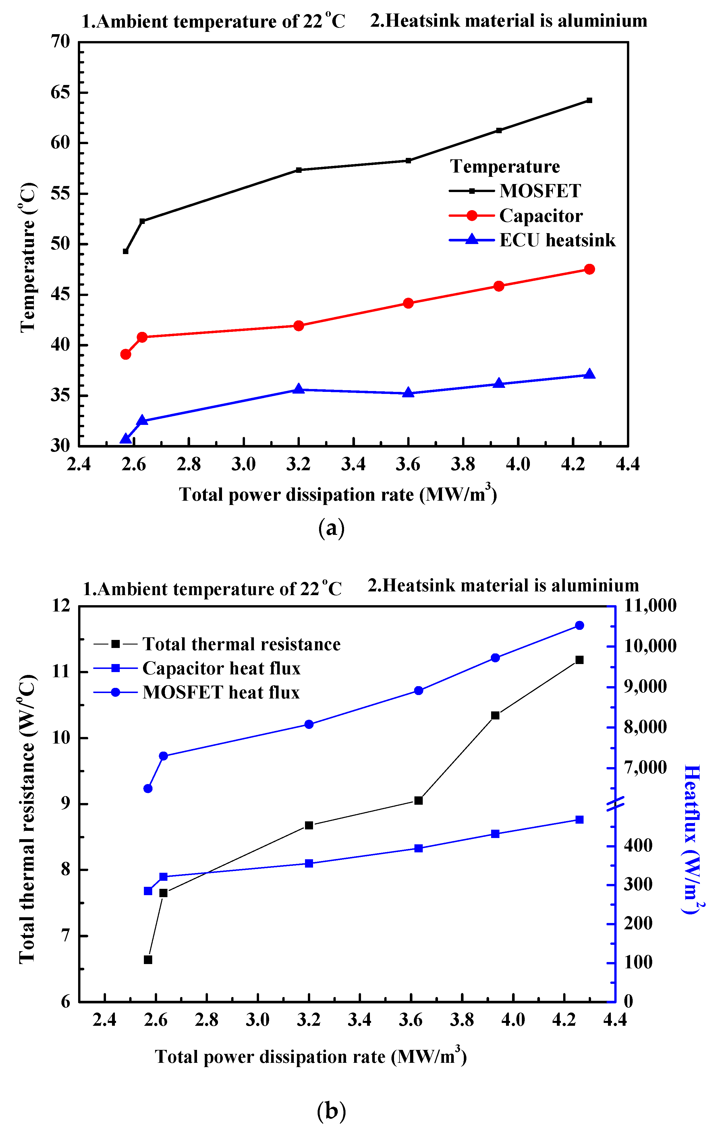
As shown in Figure 10a, the temperatures of the ECU heatsink, the MOSFETs and the capacitors of the 36V ECU system at a total power dissipation of 4.26 MW/m3 were higher by 20.95%, 30.31% and 21.54% °C than those at the total power dissipation of 2.57 MW/m3. This could be due to an increased generation of heat with the increased flow of input current to the capacitors and the MOSFETs. This results in an increased generation of heat by the Joule effect [40]. The heat generation of the semiconductors depends on the input power. The existing model had a total power dissipation rate of 3.2 MW/m3 and it showed 110,094.85 W/m2, 80,051.32 W/m2 and 14,687.81 W/m2 heat flux for the MOSFETs, the capacitors and the heatsink respectively.
In comparison to the power dissipation rate of the existing model, as shown in Figure 10b, the heat flux of MOSFETs and the capacitors decreased by 19.75% and 19.92% respectively when the total power dissipation rate was decreased by 20%. The heat generation in the MOSFET and the capacitors increased when the power dissipation rate was increased by 30% in comparison to the existing model. According to Equation (14), this results in an increase in the thermal energy of all other elements. Thus, the heat flux values for the MOSFETs, capacitors and the heatsink increased by 30.10% and 31.68%, respectively, compared to the existing model. The total thermal resistance of the existing aluminum heatsink ECU system was 8.67 °C/W. When the total power dissipation rate of the existing system was decreased by 20%, the thermal resistance of the system decreased by 6.63%. When the total power of the ECU system was increased by 30%, the total thermal resistance increased by 11.18%. This is due to increased generation of heat corresponding to increased temperature of the ECU system [41].
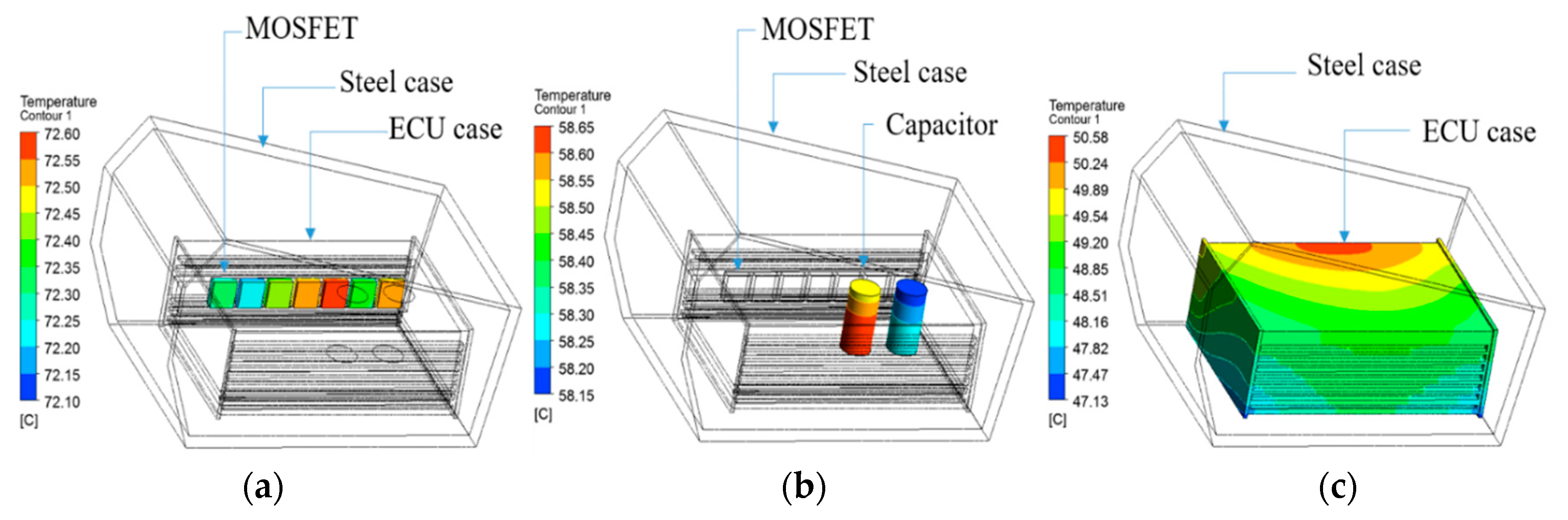
Figure 11 shows the variation of temperatures of the heatsink, seven MOSFETs and the two capacitors of the 36V ECU system with the ambient temperature. At an ambient temperature of −20 °C, the temperatures of the heatsink, seven MOSFETs and the two capacitors were −9.02 °C, 13.6 °C, 0.55 °C, respectively. With the increase of the ambient temperatures from 20 °C to 30 °C, the temperatures of the ECU heatsink, seven MOSFETs and the two capacitors increased by 32.93%, 24.86% and 25.14%, respectively. The temperatures of the ECU heatsink, seven MOSFETs and the two capacitors increased by 24.75%, 9.93% and 22.04%, respectively, with the increase of the ambient temperatures from 30 °C to 40 °C. The temperatures of the heatsink, seven MOSFETs and the two capacitors were 50.81 °C, 72.75 °C, 58.81 °C, respectively when the ambient temperature was 40 °C. This increase in the temperatures of the heatsink, MOSFETs and the capacitors with increasing ambient temperatures is a result of the decreased heat transfer rate. The decreased heat transfer rate is due to the decrease in the temperature difference between the ECU system and the environment. The heat generation of the capacitors did not specifically depend on the ambient temperatures because these temperatures did not directly affect the ESR value as given by Equation (13) [42]. In this study, the maximum temperatures of the MOSFET, capacitor and heatsink were recorded, when the ambient temperature was 40 °C. Figure 12 shows the temperature distribution of the MOSFETs, capacitors and heatsink when the ambient temperature is 40 °C. As shown in Figure 12a, MOSFETs that are located near the middle of the PCB showed a higher temperature than other MOSFETs. As shown in Figure 12b, the inner capacitor also showed a higher temperature than the outer capacitor due to the outer MOSFETs and outer capacitor being located near the ends of the PCB. These areas of the ECU show lower temperatures as shown in Figure 12c. Furthermore, the part of the heatsink near the MOSFETs showed a higher temperature due to the temperature of the MOSFET.
5. Conclusions
The objective of this study was to numerically investigate the heat transfer characteristics of the 36V ECU system with seven MOSFETs and two capacitors, for an electric bicycle with variations of the ambient temperature, thermal conductivity of the thermal grease, ECU heatsink material and power dissipation. The numerical results of the temperatures of the MOSFET and the ECU heatsink of the 36V ECU heatsink system were validated within 7.2% and 2.1%, respectively, with the experimental results. The temperatures of the heatsink, seven MOSFETs and two capacitors increased with the increase of the ambient temperature and with the increase of the total power dissipation. The temperatures of the heatsink, seven MOSFETs and two capacitors can be decreased by using thermal grease with a higher thermal conductivity between the heatsink and MOSFETs, using copper as a manufacturing material for the ECU heatsinks.
Author Contributions
G.E. played a leading role in writing the paper as a first author. M.-Y.L. is the corresponding author and designed the paper. M.S.P. and J.-H.S. are co-author and helped to write the part of the results and discussions in the article also analyzed the data obtained by experiment.
Funding
This work was supported by Bicycle and Marine Leisure Equipment’s Technology Development Program of MOTIE [20161016] and this research was supported by Basic Science Research Program through the National Research Foundation of Korea (NRF) funded by the Ministry of Education (2016R1D1A1B03935822).
Conflicts of Interest
The authors declare no conflict of interest.
Nomenclature
| Dynamic fluid viscosity | (Ns/m2) | ||
| Fluid density | (kg/m3) | ||
| A | Surface area | (m2) | |
| cp | Specific heat capacity | (J/kgK) | |
| f | Frequency | (Hz) | |
| GND | Ground connection | ||
| h | Height | (m) | |
| H | Specific Static (thermodynamic) enthalpy | (m2/s2) | |
| I | Current | (A) | |
| k | Thermal conductivity | (W/m K) | |
| L | Characteristic length | (m) | |
| l | Length | (m) | |
| m | Mass of the substance | (kg) | |
| p | Static pressure | (Pa) | |
| PD | Power dissipation | (W) | |
| Q | Thermal energy | (W) | |
| q | Heat transfer rate | (W) | |
| q’ | Heat flux | (W/m2) | |
| R | Resistance | (Ω) | |
| Re | Reynolds number | ||
| RTH | Thermal resistance | °C /W | |
| rms | Root mean square | ||
| SE | Energy Source | (W/m3) | |
| SM | Momentum source | (N/m3) | |
| T | Temperature | (K, °C) | |
| u | Air flow velocity | (m/s) | |
| U | Vector of fluid velocity | (m/s) | |
| V | Voltage | (V) | |
| +VS | Supply voltage (+) | (V) | |
| VOUT | Output voltage | (V) | |
| w | Width | (m) | |
| ΔT | Temperature difference | (K, °C) | |
| τ | Molecular stress tensor | (Pa) | |
| Gradient operator | |||
| Subscript | |||
| ∞ | Ambient | ||
| DS(ON) | Static drain-source on | ||
| E | Energy | ||
| F | Fluid | ||
| IN | Inlet | ||
| OUT | Outlet | ||
| M | Momentum | ||
| PCB | Printed circuit board | ||
| RSS | Small-signal reverse | ||
| S | Solid | ||
| SW | Switching | ||
| TG | Thermal grease | ||
| TH | Thermal | ||
References
- Melino, S.; Petrillo, A.; Cigolotti, V.; Autorino, C.; Jannelli, E.; Ulgiati, S. A Life Cycle Assessment of lithium battery and hydrogen-FC powered electric bicycles searching for cleaner solutions to urban mobility. Int. J. Hydrogen Energy 2017, 42, 1830–1840. [Google Scholar] [CrossRef]
- Mitchell, W.J.; Borroni-Bird, C.E.; Burns, L.D. Reinventing the Automobile-Personal Urban Mobility for the 21st Centuary; The MIT Press Cambridge: Cambridge, MA, USA, 2009; pp. 156–188. [Google Scholar]
- Cairns, S.; Behrendt, F.; Raffo, D.; Beaumont, C.; Kiefer, C. Electrically-assisted bikes: Potential impacts on travel behavior. Transp. Res. Part A 2017, 103, 327–342. [Google Scholar] [CrossRef]
- Vereniging, R.A.I. Statistics Rijwiel en Automobiel Industrie. 2013. Available online: http://www.raivereniging.nl/actueel/go-mobility/go-mobilitynieuwsbrief/20130124-een-miljoenste-ebike-verkocht.aspx (accessed on 3 March 2018).
- Gehlert, T.; Kühn, M.; Schleinitz, K.; Petzoldt, T.; Schwanitz, S.; Gerike, R. The German pedelec naturalistic cycling study e study design and first experiences proceedings. In Proceedings of the International Cycling Safety Conference, Helmond, The Netherlands, 7–8 November 2012; pp. 7–8. [Google Scholar]
- Shuguang, J.; Christopher, R.C.; Lee, D.H.; David, A.J. Electric bike sharing: Simulation of user demand and system availability. J. Clean. Prod. 2014, 85, 250–257. [Google Scholar]
- Weinert, J.; Ogden, J.; Sperling, D.; Burke, A. The future of electric two-wheelers and electric vehicles in China. Energy Policy 2008, 36, 2544–2555. [Google Scholar] [CrossRef] [Green Version]
- Jones, T.; Harms, L.; Heinenc, E. Motives. Perceptions and experiences of electric bicycle owners and implications for health, wellbeing and mobility. J. Transp. Geogr. 2016, 53, 41–49. [Google Scholar] [CrossRef]
- Kennedy, B.; Patterson, D.; Camilleri, S. Use of lithium-ion batteries in electric vehicle. J. Power Sources 2000, 90, 156–162. [Google Scholar] [CrossRef]
- Chen, S.C.; Wan, C.C.; Wang, Y.Y. Thermal analysis of lithium-ion batteries. J. Power Sources 2005, 140, 111–124. [Google Scholar] [CrossRef]
- Dumitrache, F.; Carp, M.C.; Pana, G. E-bike electronic control unit. In Proceedings of the IEEE 22nd International Symposium for Design and Technology in Electronic Packaging, Oradea, Romania, 20–23 October 2016. [Google Scholar]
- Altounmaime, R.; Altounmaime, T.; Padhya, B.P.U. Characteristics and Control of the Motor System in E-Bikes. Master’s Thesis, School of Engineering, Blekinge Institute of Technology, Karlskrona, Sweden, 14 May 2014. [Google Scholar]
- Cong, J. Design of Electric Bicycle Controller. Comput. Inf. Sci. 2009, 2, 126–130. [Google Scholar] [CrossRef]
- Pascot, C.; Dandeville, Y.; Scudeller, Y.; Guillemet, P.; Brousse, T. Calorimetric measurement of the heat generated by a Double-Layer Capacitor cell under cycling. Thermochim. Acta 2010, 510, 53–60. [Google Scholar] [CrossRef]
- Kim, J.K.; Ignatova, V.A.; Heitmann, J.; Oberbeck, L. Deposition temperature effect on electrical properties and interface of high-k ZrO2 capacitor. J. Phys. Appl. Phys. 2008, 41, 1–6. [Google Scholar] [CrossRef]
- Bang, Y.M.; Patil, M.S.; Kim, D.W.; Seo, J.H.; Lee, M.Y. Numerical Study on the Thermal Performance of Battery Applying Cell Array Guide for NEV. In Proceedings of the KSME Thermal Engineering Division, Yeosu, Korea, 16 June 2016; pp. 362–363. [Google Scholar]
- ANSYS® Academic Research, Release 16.2; ANSYS: Pittsburgh, PA, USA, 2015.
- Soni, A. Study of thermal performance between plate-fin, pin-fin, and elliptical fin heat sink in closed enclosed under natural convection. Int. Adv. Res. J. Sci. Eng. Technol. 2016, 3, 133–139. [Google Scholar]
- Patil, M.S.; Seo, J.H.; Kim, D.W.; Kim, C.J.; Lee, G.S.; Kim, M.Y.; Kim, K.-H.; Lee, M.Y. Thermo-fluid Simulation for the thermal performances of the 72V ECU cooling system with heatsink for a light electric vehicle. J. Adv. Res. Dyn. Control Syst. 2018, 10, 199–210. [Google Scholar]
- Newman, J. Physics of the Life Sciences. Available online: http://www.if.ufrj.b/~coelho/Newman/Newman12.pdf (accessed on 3 March 2018).
- Christensen, A.; Graham, G. Thermal effects in packaging high power light emitting diode arrays. Appl. Therm. Eng. 2009, 29, 364–371. [Google Scholar] [CrossRef]
- Holman, J.P. Heat Transfer, 10th ed.; The McGraw-Hill Companies: New York, NY, USA, 2010; pp. 48–120. [Google Scholar]
- Lee, H.S.; Cho, C.W.; Seo, J.H. Cooling performance characteristics of the stack thermal management system for fuel cell electric vehicle under actual driving conditions. Energies 2016, 9, 320. [Google Scholar] [CrossRef]
- Lienhard, J.H. On the Commonality of Equations for Natural Convection from Immersed Bodies. Int. J. Heat Mass Transf. 1973, 16, 2121–2123. [Google Scholar] [CrossRef]
- Climate: Observations Projections and Impacts—South Korea. Available online: http://eprints.nottingham.ac.uk/2040/19/Republic_of_Korea.pdf (accessed on 3 March 2018).
- Data Sheet of SiHFZ34 MOSFET. Available online: https://www.vishay.com/docs/91290/91290.pdf (accessed on 3 March 2018).
- Data Sheet of CD288H Capacitor. Available online: http://www.vek-online.de/files/4188/upload/Elektrolyt/CD288H.pdf (accessed on 3 March 2018).
- Gwinn, J.P.; WebbR, L. Performance and testing of thermal interface materials. Microelectron. J. 2003, 34, 215–222. [Google Scholar] [CrossRef]
- Thermal Interface Materials for Electronics Cooling-Products and Custom Solutions Catalog. Available online: https://www.parker.com/literature/Chomerics/Parker%20Chomerics%20Thermal%20Catalog.pdf (accessed on 3 March 2018).
- Al-Hagag, Q.R.; Bassil, M.H.; Al-Janab, M.Y. Optimum Design of Rectangular Plate Heat Sink. Available online: http://www.uobabylon.edu.iq/uobcoleges/fileshare/articles/opt,final2.pdf (accessed on 3 March 2018).
- Terry, M.T. Thermal Conductivity: Theory, Properties and Applications; 2nd Series; Kluwer Academic/Plenum Publishers: New York, NY, USA, 2004; pp. 21–88. [Google Scholar]
- Mondolfo, L.F. Aluminium Alloys: Structure and Properties, 1st ed.; Buttereorth & Co Ltd.: London, UK, 1979; pp. 56–68. [Google Scholar]
- Wasserman, E.; Stixrude, L.; Cohen, R.E. Thermal properties of iron at high pressures and temperatures. Phys. Rev. B 1996, 53, 82–96. [Google Scholar] [CrossRef]
- Iyengar, M. Design For Manufacturability Of Forced Convection Air Cooled Fully Ducted Heat Sinks. Electron. Cool. Mag. 2007, 13, 22–26. [Google Scholar]
- Mallik, S.; Ekere, N.; Best, C.; Bhatti, R. Investigation of thermal management materials for automotive electronic control units. Appl. Therm. Eng. 2011, 31, 355–362. [Google Scholar] [CrossRef] [Green Version]
- Sullivan, O.C. Newton’s law of cooling—A critical assessment. Am. J. Phys. 1990, 58, 956–960. [Google Scholar] [CrossRef]
- The Physics Factbook. Available online: https://hypertextbook.com/facts/2004/KarenSutherland.shtml (accessed on 3 March 2018).
- Worrell, E.; Price, L.; Martin, N.; Farla, J.; Schaeffer, R. Energy Intensity in the Iron and Steel Industry: A comparison of physical and economi Indicators. Energy Policy 1997, 25, 727–744. [Google Scholar] [CrossRef]
- Keller, K. Low Cost, High Performance, High Volume Heatsinks. Available online: http://www.cs.unc.edu/~pxfl/papers/low_cost1.pdf (accessed on 3 March 2018).
- Schiffer, J.; Linzen, D.; Sauer, D.U. Heat generation in double layer capacitors. J. Power Sources 2006, 160, 765–772. [Google Scholar] [CrossRef]
- Olson, J.R. Thermal conductivity of some common cryostat materials between 0.05 and 2 K. Cryogenics 1993, 7, 729–731. [Google Scholar] [CrossRef]
- Tse, R.; Cannon, M.; Coe, J. Frequently Asked Questions Regarding: ESR Perfomance with Temperature; TDK Components Inc.: Lincolnshire, IL, USA. Available online: http://www.digikey.kr/Web%20Export/Supplier%20Content/TDK_445/PDF/TDK_esr.pdf (accessed on 3 March 2018).
Figure 1.
Power train of electrical bicycle.

Figure 2.
Numerical model of the 36V electronic control unit (ECU) system. (a) 3D design of the ECU outer case which works as the heatsink: (b) Locations of the major components’ inside the ECU; (c) Location of ECU inside the steel chamber of the bicycle and the boundary conditions.
Figure 2.
Numerical model of the 36V electronic control unit (ECU) system. (a) 3D design of the ECU outer case which works as the heatsink: (b) Locations of the major components’ inside the ECU; (c) Location of ECU inside the steel chamber of the bicycle and the boundary conditions.

Figure 3.
Thermal resistance model of the 36V ECU system.

Figure 4.
Meshing details of the 36V ECU: (a) Variation of the maximum temperature of the capacitor, metal-oxide-silicon field effect transistor (MOSFET) and the ECU case with the number of grids; (b) Meshing details for the ECU outer case; (c) Meshing details for the ECU major components including printed circuit board (PCB), capacitors and MOSFETs.

Figure 5.
The electric circuit diagram of the 36V electronic control unit (ECU) system.

Figure 6.
Experiment setup of the 36V electric bicycle: (a) 36V electric bicycle with the experimental equipment; (b) Schematic diagram of the numerical set-up of the 36V electric bicycle ECU.
Figure 6.
Experiment setup of the 36V electric bicycle: (a) 36V electric bicycle with the experimental equipment; (b) Schematic diagram of the numerical set-up of the 36V electric bicycle ECU.

Figure 7.
Experimental and numerical results of the temperature of the ECU heatsink for the 36V ECU system at a speed of 30 km/h and an ambient temperature of 22 °C.
Figure 7.
Experimental and numerical results of the temperature of the ECU heatsink for the 36V ECU system at a speed of 30 km/h and an ambient temperature of 22 °C.

Figure 8.
Variation of the temperatures of the MOSFET and the capacitor of the 36V ECU system with the thermal conductivity of the thermal grease.
Figure 8.
Variation of the temperatures of the MOSFET and the capacitor of the 36V ECU system with the thermal conductivity of the thermal grease.

Figure 9.
Temperature, total thermal resistance and heat flux of the 36V heatsink ECU system with different ECU heatsinks: (a) Maximum temperature variations; (b) Total thermal resistance and heat flux variations with the heatsink material.
Figure 9.
Temperature, total thermal resistance and heat flux of the 36V heatsink ECU system with different ECU heatsinks: (a) Maximum temperature variations; (b) Total thermal resistance and heat flux variations with the heatsink material.

Figure 10.
Temperature, total thermal resistance and heat flux of the 36V ECU heatsink with the total power dissipation rate: (a) Maximum temperature variation with the total power dissipation; (b) Total thermal resistance and heat flux variation with the total power dissipation.
Figure 10.
Temperature, total thermal resistance and heat flux of the 36V ECU heatsink with the total power dissipation rate: (a) Maximum temperature variation with the total power dissipation; (b) Total thermal resistance and heat flux variation with the total power dissipation.

Figure 11.
Variationof the temperatures of the ECU heatsink, MOSFET and the capacitor of the 36V ECU system with the ambient temperature.
Figure 11.
Variationof the temperatures of the ECU heatsink, MOSFET and the capacitor of the 36V ECU system with the ambient temperature.

Figure 12.
Temperature distribution of the MOSFET, capacitor and ECU when ambient temperature is 40 °C: (a) Temperature distribution of the MOSFETs; (b) Temperature distribution of the capacitors; (c) Temperature distribution of the heatsink (ECU case).
Figure 12.
Temperature distribution of the MOSFET, capacitor and ECU when ambient temperature is 40 °C: (a) Temperature distribution of the MOSFETs; (b) Temperature distribution of the capacitors; (c) Temperature distribution of the heatsink (ECU case).


Table 1.
Heatsink specifications.
| Item | Specifications |
|---|---|
| Overall size (w × l × h, mm3) | 65.7 × 98.6 × 32.9 |
| Maximum thickness (mm) | 4.5 |
| Minimum thickness (mm) | 2 |
| Maximum fin length (mm) | 98.6 |
| Maximum fin height (mm) | 2.7 |
| Maximum fin pitch (mm) | 3.9 |
| Total surface area (mm2) | 65,171 |
Table 2.
Specifications of the electronic control unit (ECU)
| Component | Material | Thermal Conductivity (W/m °C) | Density (kg/m3) | Specific Heat Capacity (J/kg °C) |
|---|---|---|---|---|
| Heatsink | Aluminum | 237 | 2702 | 930 |
| Capacitor | Aluminum oxide | 30 | 3890 | 880 |
| MOSFET | Silicon | 150 | 2390 | 7120 |
| Thermal grease | Silicon carbide | 0.42 | 2500 | 750 |
| PCB | Copper and Plastic | 0.4 | 855 | 2300 |
Table 3.
Applied conditions for the numerical simulation of the 36V electric bicycle ECU.
| Variables | Specifications |
|---|---|
| Capacitor and MOSFET total power dissipation (MW/m3) | 2.57, 2.63, 3.20, 3.60, 3.93, 4.26 |
| Thermal conductivity of thermal grease material (W/m °C) | 0.01, 0.2, 0.4, 0.6, 0.8, 1.5, 2.4, 5 |
| Ambient temperatures (°C) | −20, −10, 0, +10, +20, +30, +40 |
| Heatsink manufacturing material | Aluminum, Iron, Steel, aluminum alloy, Copper |
Table 4.
Specifications of the Li-ion battery.
| Item | Specification |
|---|---|
| Nominal voltage (V) | 36.0 |
| Nominal capacity (Ah) | 10.4 |
| Charging voltage (V) | 42.0 |
| Discharging current (A) | 10.0 |
Table 5.
Test conditions.
| Item | Specification |
|---|---|
| Velocity (km/h) | 30 |
| Ambient temperature (°C) | 22 |
| Test time (s) | 1500 |
| Average weight of the rider (kg) | 70 |
| Bicycle weight (kg) | 26 |
© 2018 by the authors. Licensee MDPI, Basel, Switzerland. This article is an open access article distributed under the terms and conditions of the Creative Commons Attribution (CC BY) license (http://creativecommons.org/licenses/by/4.0/).
Share and Cite
MDPI and ACS Style
Ekanayake, G.; Patil, M.S.; Seo, J.-H.; Lee, M.-Y. Numerical Study on Heat Transfer Characteristics of the 36V Electronic Control Unit System for an Electric Bicycle. Energies 2018, 11, 2506. https://doi.org/10.3390/en11102506
AMA Style
Ekanayake G, Patil MS, Seo J-H, Lee M-Y. Numerical Study on Heat Transfer Characteristics of the 36V Electronic Control Unit System for an Electric Bicycle. Energies. 2018; 11(10):2506. https://doi.org/10.3390/en11102506
Chicago/Turabian StyleEkanayake, Gihan, Mahesh Suresh Patil, Jae-Hyeong Seo, and Moo-Yeon Lee. 2018. "Numerical Study on Heat Transfer Characteristics of the 36V Electronic Control Unit System for an Electric Bicycle" Energies 11, no. 10: 2506. https://doi.org/10.3390/en11102506
Note that from the first issue of 2016, this journal uses article numbers instead of page numbers. See further details here.