Article

Multi-Step Loading Creep Behavior of Red Sandstone after Thermal Treatments and a Creep Damage Model

1
State Key Laboratory for Geomechanics and Deep Underground Engineering, School of Mechanics and Civil Engineering, China University of Mining and Technology, Xuzhou 221116, China
2
Deep Earth Energy Research Laboratory, Department of Civil Engineering, Monash University, Melbourne 3800, Australia
*
Author to whom correspondence should be addressed.
Energies 2018, 11(1), 212; https://doi.org/10.3390/en11010212
Submission received: 20 December 2017 / Revised: 9 January 2018 / Accepted: 10 January 2018 / Published: 16 January 2018
(This article belongs to the Special Issue Geothermal Energy: Utilization and Technology 2018)

Abstract

:
Triaxial compressive creep tests were conducted on red sandstones after different thermal treatments. Subsequently, the thermal influence on the axial, lateral and volumetric creep curves under various stress levels was analyzed. The results show that both the instantaneous and time-based deformation behaviors depended largely on the stress and temperature conditions. The instant axial strain increases linearly with increasing deviator stress and the instant deformation modulus decreases non-linearly with temperature. An interesting phenomenon was observed whereby the lateral creep strain had an apparent linear correlation with the axial creep strain. Furthermore, the fitting lines’ slopes of lateral and axial creep strain increase gradually with the increasing deviator stress at identical temperature and first decreases and then increases as temperature is elevated. Then, on the basis of the Burgers creep model and the concept of strain energy, a creep damage model implemented in FLAC3D (Fast Lagrangian Analysis of Continua 3D) is presented, and this model was able to describe the entire creep process completely including primary creep stage, secondary creep stage, and tertiary creep stage comparing with the experimental and theoretical results based on test data and numerical calculations. The influence of two damage parameters on creep curves and the thermal influence on creep parameters are subsequently discussed. Under the same stress level, the parameters K, GM and GK and ηK of creep model decrease with temperature, while the parameter ηM first augments as temperature rise to 300 °C and then decreases as temperature at above 300 °C. The higher is the temperature, the smaller the critical stress ratio (CSR).

1. Introduction

The exploration and exploitation of deep resources are not only necessary for the economic and social development for many countries, but also require solutions to basic theoretical problems. Compared with conventional fossil fuels, for instance coal and oil, geothermal energy is one of the most abundant sources of energy, which offers great advantages in cost, reliability and environmental friendliness [1,2,3,4]. This has stimulated further investigation on the mechanical behavior of rock at high pressure and temperature. Especially, deep rock masses are subjected to high pressures and temperatures, especially in engineering applications for which the temperature approaches the rock melting point, such as coal gasification underground, where the temperature can exceed 1000 °C [5,6,7], volcano flank stability [8,9,10,11], and proposals for deep geological burial of high-grade nuclear waste [12,13,14], and underground coal fires such as the spontaneous combustion of coal seams, where the maximum temperature reaches 1200 °C [15]. Rock masses involved in projects such as post-disaster reconstruction after coal fires and underground coal gasification have experienced high temperature treatments that have a vital influence on their mechanical behavior [16,17].
Therefore, research on underground rock engineering long-term stability is necessary. The influence of temperature on the rheological behavior of rock has been investigated very early [18,19,20]. Numerous researchers have conducted a variety of creep experiments that primarily considered the influence of different mineral component [21], temperature [10,22], water [23,24], pore water pressure [11,25], and stress [26,27,28] on the time-dependent behaviors of various rocks. The results show that time-based deformation in brittle rocks is not distinguishable from that in soft rock [11,29,30] and that creep rupture occurs suddenly and over very short times. Commonly, creep deformation presents three stages: transient creep with decreasing strain rate, followed by steady creep at a constant strain rate, and finally tertiary creep with sudden increases in strain rate to rupture [31]. To understand the thermal influence on the creep behaviors of rocks, Chopra [32] investigated the transient creep behaviors of two natural dunite specimens at temperatures between 1373 and 1573 K. Ferrero [33] heated marbles at a ratio of 2.4 °C/min to target temperatures and then cooled them at a ratio of 0.23 °C/min to induce micro-cracking, and then studied their mechanical behaviors. Du et al. [34] studied the mechanical properties, including stress-strain curve, peak stress and strain, elastic modulus and Poisson’s ratio of granite after subjected high temperatures. Heap et al. [10] reported the results of the thermal effects on both short-term strength and time-dependent brittle creep in three sandstones under tri-axial stress conditions. Brotóns et al. [35] investigated the influence of temperature and cooling method (air cooling and water cooling) on the physical and mechanical properties of San Julian’ stone. Tian et al. [36,37] summarized in a review the literature on the physical and mechanical properties of sandstones after high-temperature treatment. Tian et al. [38] investigated the physical and mechanical behaviors of claystone exposed to 1000 °C. Li et al. [39] studied the dynamic properties of sandstones with different strain rate after 800 °C. Ye et al. [40] conducted triaxial compression and creep tests on green tuff over temperatures ranging from 20 to 80 °C and found that peak strength and creep failure time were sensitive to temperature. Sun et al., [41] reported the variations of thermal conductivity, thermal diffusivity and heat capacity of sandstone after high temperature treatment. Yang et al. [1] evaluated the thermal damage and failure mechanical behavior of granite at elevated temperatures, which demonstrated that the crack damage threshold, the strength and static elastic modulus of granite were increased at 300 °C, before decreasing up to the maximum temperature of 800 °C. Yang et al. [2] investigated the triaxial mechanical and permeability behavior of sandstone after exposure to different high temperature treatments.
In addition, proper constitutive models for time-related behaviors of rocks have been abundantly researched. In general, those models can be divided into three distinct methods: (1) empirical models [42,43]; (2) component models [44,45,46]; and (3) models based on inner mechanisms such as endochronic theory [47,48], thermodynamics [49,50] and damage and fracture mechanics [51,52,53]. The damage concept was first introduced by Kachanov [54] and elaborated by Lemaitre [55]. The damage model of Kachanov is classified as isotropic damage. The damage model of Kachanov is extended to anisotropic damage by Murakami [56] and this concept was applied to rock mass by Kyoya [57] and it is called damage tensor. Previous research has shown that damage reflected by, for example, porosity changes, cumulative acoustic emission energy and microscopic crack observations during creep processes, occurs in time-dependent rock deformation [10,11,27,58,59]. Furthermore, the damage mechanisms include mainly stress corrosion, the initiation [60,61], propagation and coalescence of microcracks, and energy dissipation [62,63]. However, little has been reported on simple and effective creep models for characterizing trimodal creep behavior.
To better understand the influence of temperature on the creep behavior of brittle rocks, this paper presents the results of triaxial compressive creep tests on red sandstones under confining pressures (σ3) of 25 MPa after thermal treatments (25, 300, 700 and 1000 °C) and a detailed analysis and discussion of the results. Simultaneously, it is necessary to develop an appropriate and simple creep damage model to characterize the time-based deformation and damage characteristics to better understand the creep mechanisms of brittle rock. Finally, a simple creep damage model is proposed considering strain energy and based on a Burgers model.

2. Experiments

2.1. Specimen Preparation

The red sandstones were obtained from Rizhao (Shandong Province, China). Specimens were cut and polished to form cylinders with diameters of 50 mm and height-to-width ratios of 2:1. They were then dried for approximately 24 h at a temperature of 105 °C in a drying box (SGM High temperature Electric Furnace Limited Company, Shanghai, China). Finally, the specimens were heated to 300 °C, 700 °C and 1000 °C in a furnace (SGM High temperature Electric Furnace Limited Company, Shanghai, China) at a rate of 5 °C/min, after which the temperatures were maintained for 2 h before being allowed to cool to room temperature. The basic parameters of the tested samples are listed in Table 1.

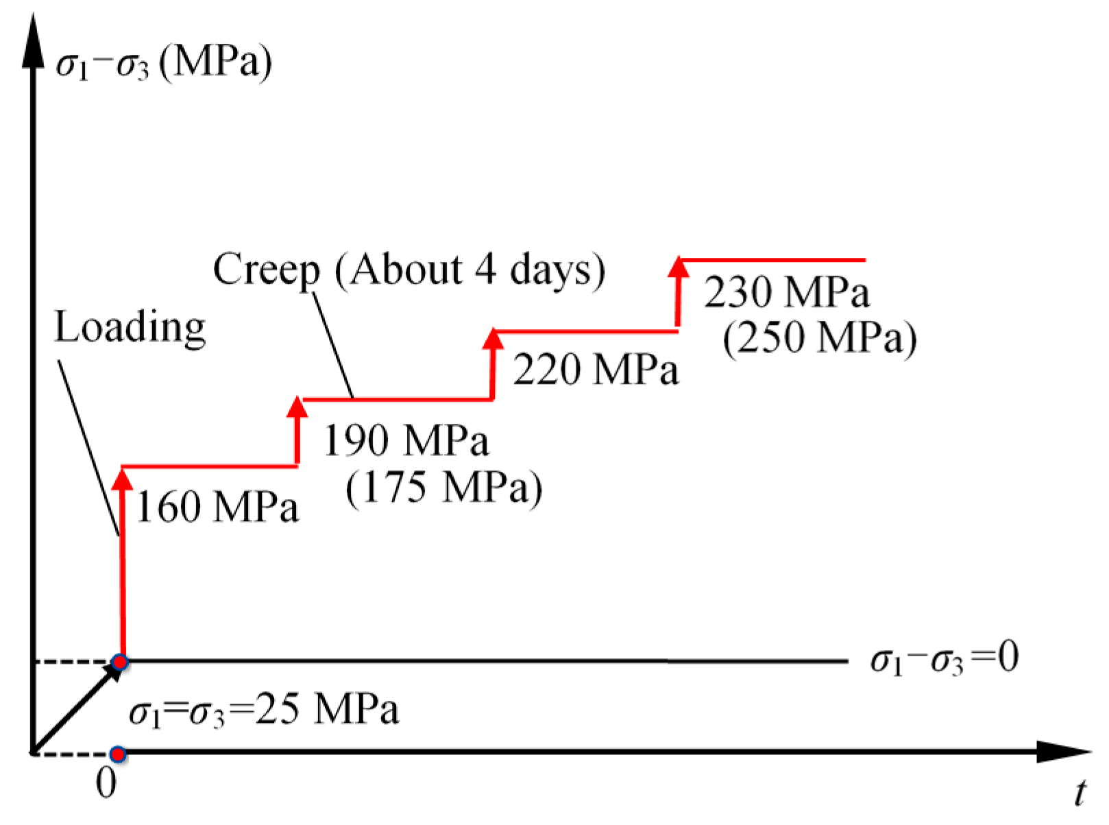
2.2. Testing Apparatus and Method

Rock triaxial rheological testing equipment (TOP INDUSTRIE, Grand Paris, France), whose allowed maximum values of deviatoric stress, confining pressure and pore pressure with water were 400, 70 and 40 MPa, respectively, was used to perform creep experiments. In an effort to overcome the influence of specimen differences, a stress stepping methodology was adopted for a single specimen; until the specimen eventually ruptured [27]. Hence, the specimens were first subjected to hydrostatic pressures of 25 MPa and deviatoric stresses were applied to 160 MPa (the first stress level was slightly greater than the lowest σcd) under pressure-controlled conditions of 5 MPa/min. They subsequently deformed for approximately 4 days under static compressive stress, after which the deviatoric stress was applied at next level. The above procedures were repeated until failure occurred. The loading procedure is shown in Figure 1.

3. Creep Experimental Results
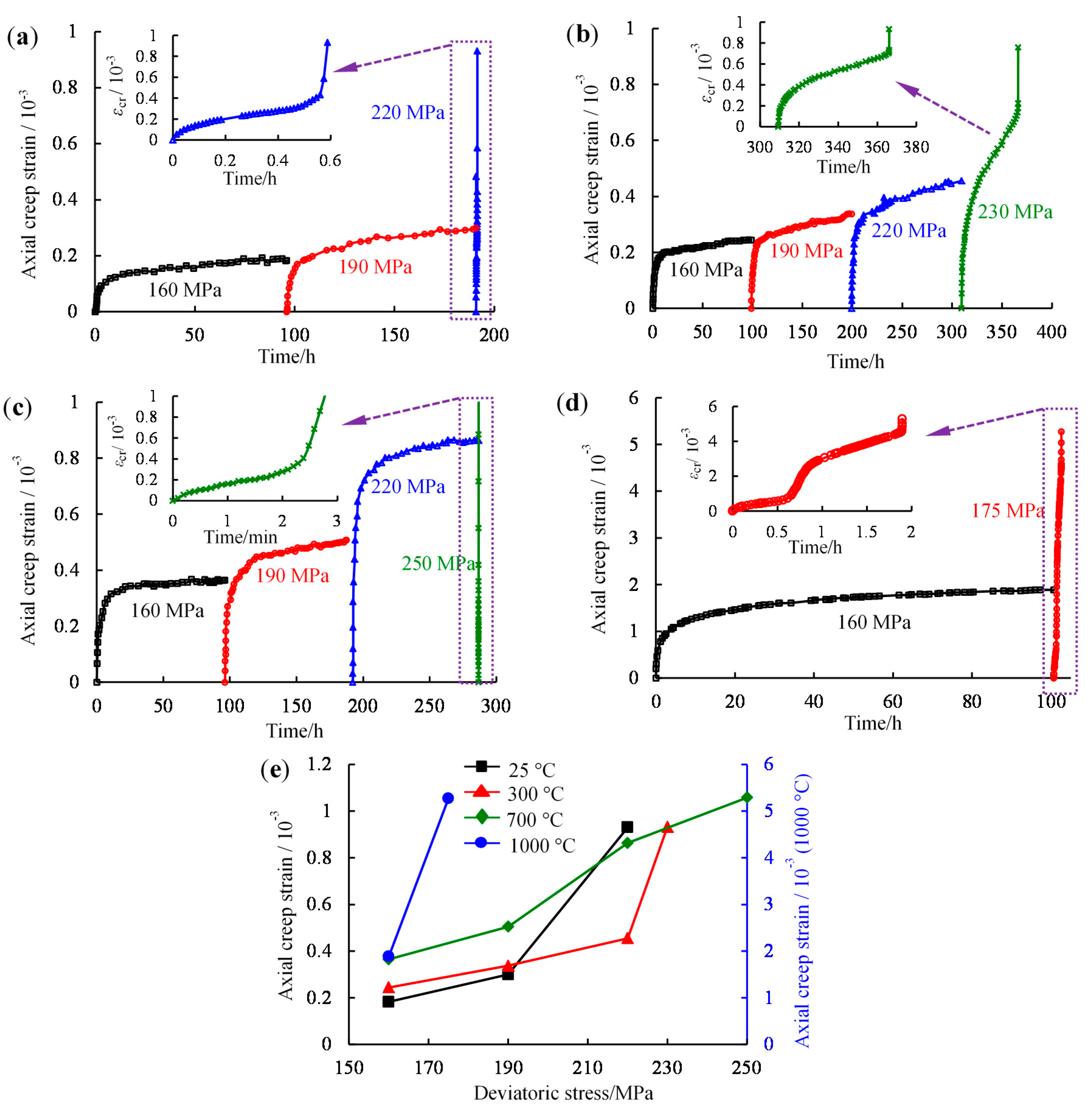
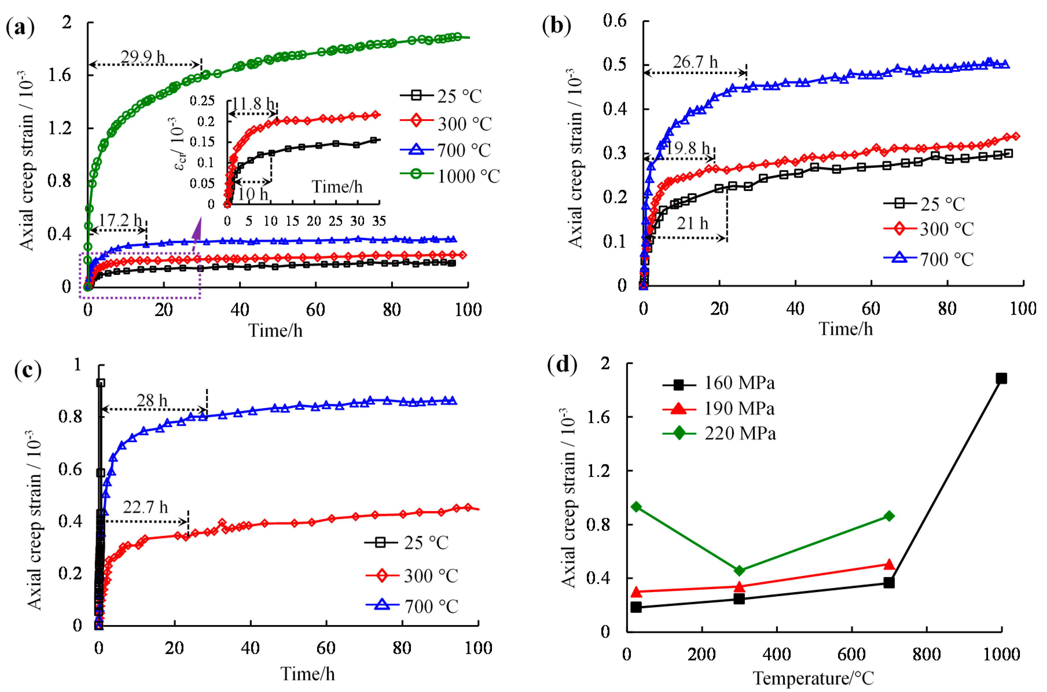
3.1. Axial Strain

The instantaneous deformation under σ3 of 25 MPa will be analyzed first. Figure 2a illustrates the relationships between instantaneous axial strain (ε0) and differential stress under different temperatures. It can be seen that the instantaneous axial strain increased linearly with increasing partial stress under the same temperatures. Moreover, the strain increments also increased gradually as the loadings increased. Approximately monotonic linear correlations between the instantaneous axial strain and deviatoric stresses were found in each thermal-treated specimen.
In particular, the fit line slopes represent the instantaneous deformation modulus (E0), which decreased with temperature, although the square of the correlation coefficient (R2) of the specimens at 1000 °C was not very high. It can be observed that the decrease in E0 with increasing temperature was non-linear. Its nonlinear correlation (for the average values at each temperature) can be fitted by the equation shown in Figure 2b.
The axial creep deformations of the specimens at different temperatures were analyzed. Figure 3 shows the variations in the axial creep strains over time for the red sandstones at temperatures of 25, 300, 700 and 1000 °C under σ3 of 25 MPa, respectively. The axial creep strains were positive, which represented axial compression. Figure 3 remarkably indicates that the axial creep strains increased over time under static loading.
As the deviatoric stresses increased, the increments in the axial creep strains rose gradually over time. Under the last loading, the durations of tertiary creep for the specimens at 25, 300, 700 and 1000 °C were approximately 35.3 min, 56.7 h, 2.7 min and 1.9 h, respectively. Commonly, brittle failure over short times at the onset of the accelerated creep stage occurred rapidly. An interesting phenomenon can be observed in Figure 3d for the specimen at 1000 °C and under a deviatoric stress of 175 MPa. Primary and steady state creep existed for approximately 0.6 h after the last stress was applied, after which tertiary creep seems to have occurred, whereas it again showed primary and secondary creep and brittle creep failure in the final accelerating creep stage. The relationship between deviatoric stress and axial creep strain at different temperatures was shown in Figure 3e, in which axial creep increased as deviatoric stress and temperature increased. Figure 4 presents the axial creep strains with creep time at various temperatures under the conditions of deviatoric stresses of 160, 190 and 220 MPa, respectively. As shown in Figure 4a, when the deviatoric stress was raised to 160 MPa, the axial creep strains and the durations of the primary creep stage increased with increasing temperature. The stress levels were 68%, 65%, 55% and 77% of each σp at 25, 300, 700 and 1000 °C, respectively. However, under deviatoric stresses of 190 MPa, the stress level were 81%, 78% and 65% of each σp at the four temperatures, and the duration of primary creep for the specimen at 300 °C was shorter than that at room temperature, as shown in Figure 4b. As shown in Figure 4c, when the deviatoric stress reached to 220 MPa, the stress level were 94%, 90% and 76% of each σp at 25 °C, 300 °C and 700 °C, respectively, and the specimen at 25 °C failed quickly, whereas the others experienced steady state creep for approximately 22.7 h and 28 h.
Figure 4d illustrates the relationship between axial creep strain and temperature at identical stress level. When deviatoric stress reached 160 and 190 MPa, axial creep strain increased with increasing temperature. Upon combining Figure 3 and Figure 4, it can be found that creep strain depended heavily on applied differential stress and temperature.

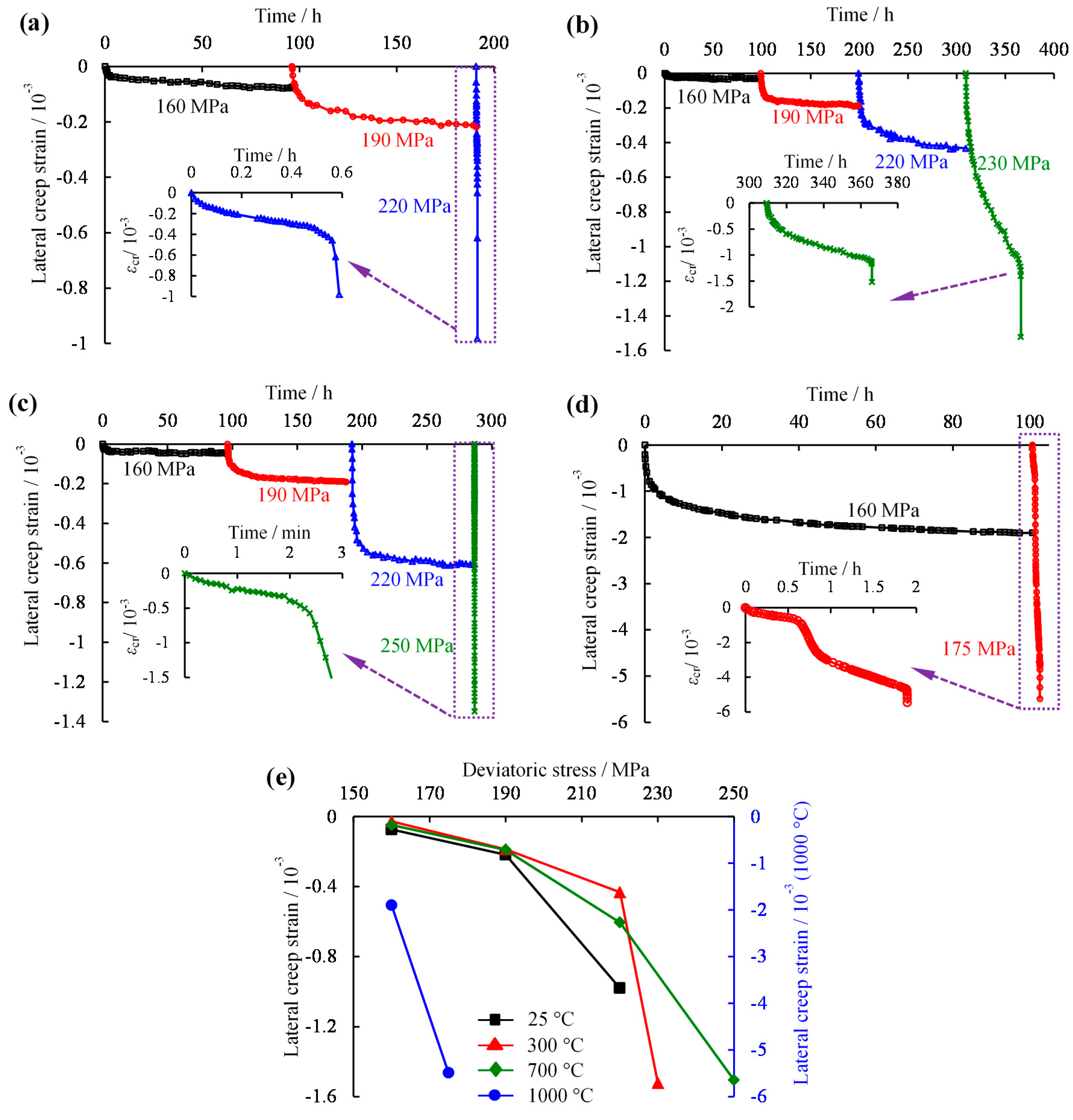
3.2. Lateral Creep Strain

Lateral deformations can reflect the influence of stress on the lateral expansion of materials. This section will investigate lateral creep strain under increasing deviatoric stress at identical temperatures and under same stresses at various temperatures. It can be seen in Figure 5 that the lateral creep strains commonly were negative, indicating lateral dilatancy. The trimodal creep behavior corresponded to the axial behavior. Lateral creep strain increased with decreasing rate over time for deviatoric stress values below σc. It rose as the partial stress increased. In particular, the creep strain increased rapidly when the loadings reached 220, 230, 250 and 175 MPa for the specimens at 25, 300, 700 and 1000 °C, respectively. That phenomenon indicates that material experienced brittle failure with rapid lateral expansion. Moreover, the relationship between lateral creep strain and deviatoric stress at different temperatures was plotted in Figure 5e.
The lateral creep strains of the specimens at different temperatures under partial stresses of 160, 190 and 220 MPa, respectively, are shown in Figure 6. In Figure 6a, it is obvious that the lateral material dilatancy at 1000 °C exceeded those of the others by in excess of an order of magnitude. Furthermore, as the temperatures increased from room temperature to 300 °C the lateral creep strains decreased remarkably but increased when the temperature increased to 700 °C. Similarly, the lateral creep strains first decreased and then increased slightly before and after 300 °C under a static stress of 190 MPa, as shown in Figure 6b. From Figure 6c, when the loading reached 220 MPa, the failure and lateral expansion of the specimens at room temperature were rapid. According to the relationship between lateral creep strain and temperature, as shown in Figure 6d, it can be concluded that the lateral creep strains first decreased at temperatures below 300 °C and then increased when the temperatures rose above 300 °C.

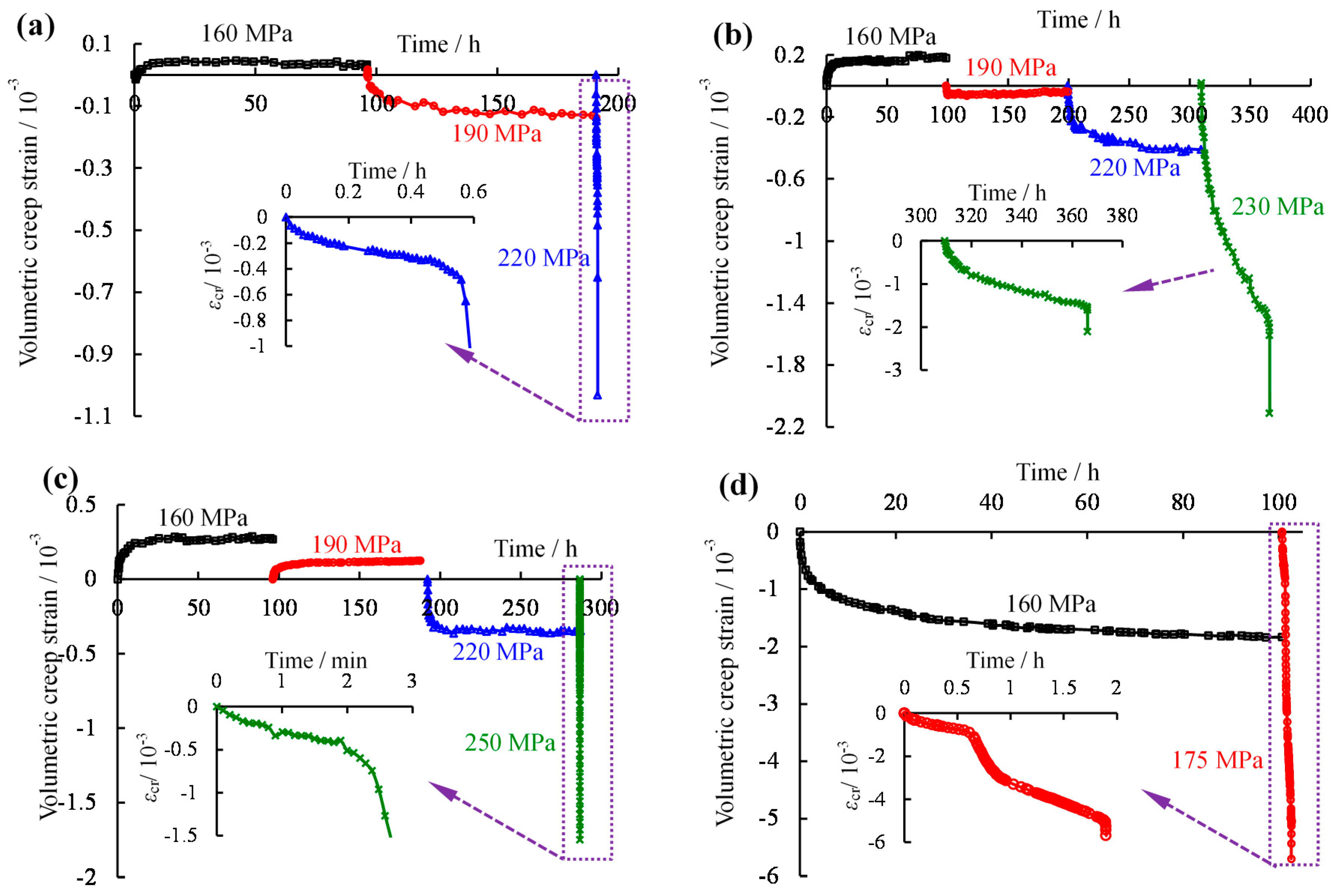
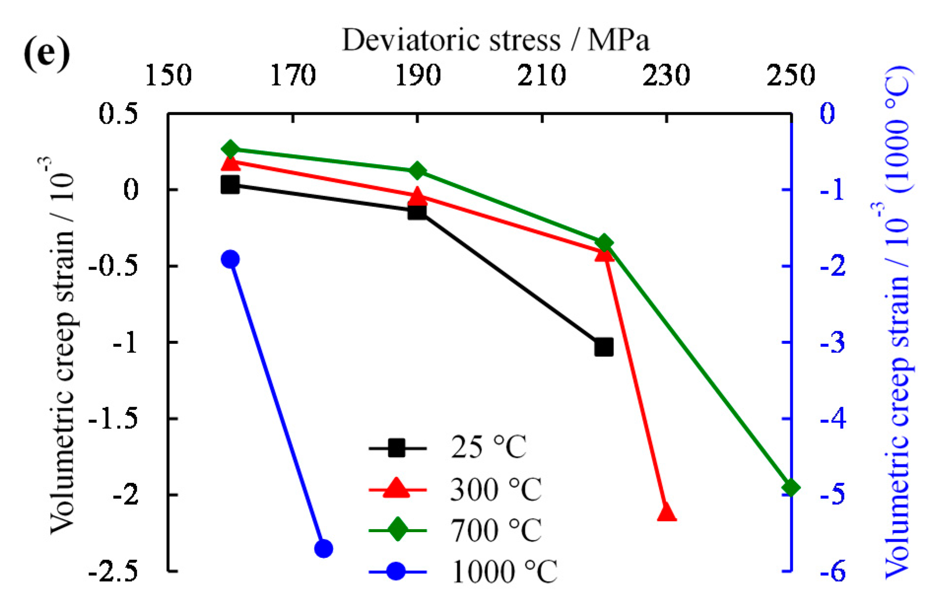
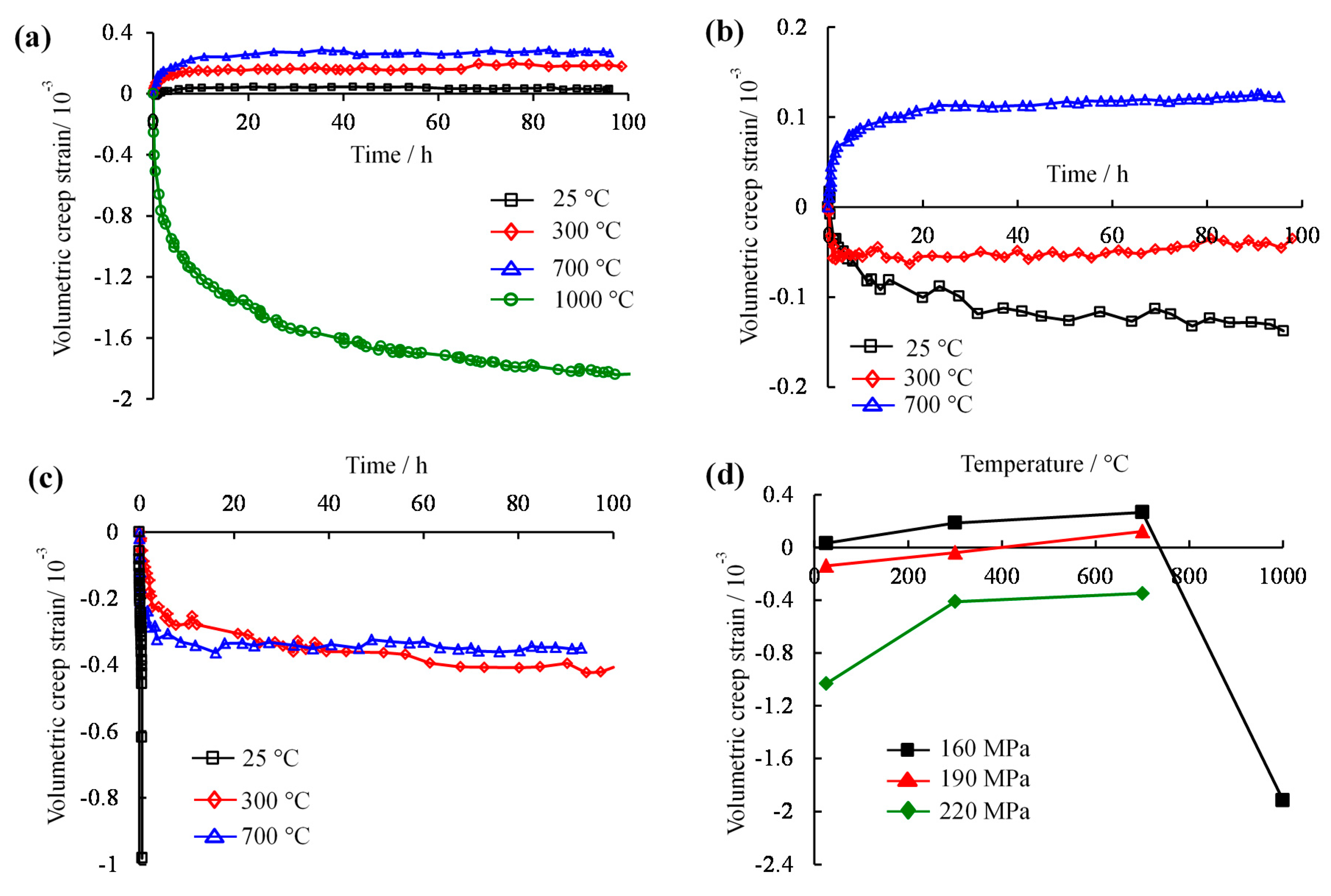
3.3. Volumetric Creep Strain

Figure 7 shows the relationships of volumetric creep strain and time under increased loading for the specimens at different temperatures. From Figure 7a, the volumetric creep strain was positive under a deviatoric stress of 160 MPa, whereas it became negative when the loading exceeded 190 MPa for the specimen at 25 °C. Analogously, the specimen at 300 °C also shows this characteristic in Figure 7b. As the temperatures were elevated to 700 °C, the volumetric creeps were positive and decreased as the deviatoric stresses increased from 160 to 190 MPa. They subsequently became negative and, in reverse, increased under the loadings exceeding 190 MPa. In particular, for the specimens at the highest temperatures, the volumetric creep strains were always negative under the deviatoric stresses of 160 and 175 MPa. According to the relationship between volumetric creep strain and deviatoric stress, as shown in Figure 7e, in which lateral expansion increased with increasing differential stress and temperature, as the stress levels gradually increased the specimens at first compressed and then dilated and eventually failed by shear dilatancy.
Figure 8 illustrates the influence of temperature on the volumetric creep strains of the specimens under different compressing stresses. From Figure 8a, the creep strains of the specimens were positive for temperatures below 1000 °C and became negative at 1000 °C. Furthermore, the negative volumetric creep strains at 1000 °C were approximately two orders of magnitude larger than the positive ones at the other temperatures under a deviatoric stress of 160 MPa.
This suggests that the former experienced shear dilatancy, whereas the latter experienced compression. When the partial stresses rose to 190 MPa, the two specimens at 25 and 300 °C were negative, indicating that the deformations were dominated by shear-dilatancy, whereas the specimen at 700 °C was still compression-dominated, or positive (Figure 8b). Because that stress level was nearer to the σp of the specimens at 25 °C, the volumetric creep slope exceeded that for 300 °C. From Figure 8c, as the stresses increased to 220 MPa, the 25 °C specimen experienced serious shear dilation in a short time, and the others behaved similarly but did not fail. This dilation was closer to the σp of the specimen at 300 °C at that stress level, and the specimen at 300 °C with a marginally higher development strain rate in comparison with that at 700 °C can be seen in Figure 8c. The relationship between volumetric creep strain and temperature were shown in Figure 8d. It is clear that compression was given prior to expansion when temperature was below 700 °C.

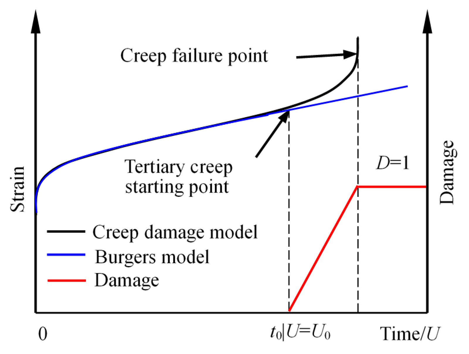
4. Creep Damage Model

Natural rocks have various scales of macro- and micro-defects, and their deformation and damage are therefore inevitably affected by those inherent flaws. In addition, their failure processes are often accompanied by the evolution, development, coalescence and interaction of cracks [13]. Therefore, rock rheological constitutive models that consider evolutionary rules of rock damage can more reasonably describe the rheological behaviors of rocks. In consequence, the following parts will introduce the damage process during the creep stage, and a creep damage model will be established.

4.1. Construction of Creep Damage Equation

Existing research shows that damage processes of rock materials are essentially processes of energy accumulation and dissipation [50]. Material damage is not only controlled by randomly distributed internal defects but also by internal stress and strain states. In view of the above discussions, strain energy can directly reflect the stress and strain states of rocks. Consequently, it is more reasonable to use strain energy as an internal variable to describe the damage evolution law [50].
Acoustic emission monitoring of rocks shows that energy increases substantially after the onset of the tertiary creep stage [11,27,64], which is accompanied by a rapid release of strain energy. Xie et al. [63] presented a relationship between damage variable and energy dissipation:
D = 1 exp ( α | U d U 0 d | β )
where Ud and U 0 d are the dissipation energy leading to rock damage and the dissipated energy corresponding to the initial damage, and α and β are parameters related to material properties.
According to previous research [65], the strain energy can be expressed as.
U = 0 ε i j σ i j d ε i j
where σij and εij are stress and strain, and (ij = 1,2,3).
This article presents a damage evolution equation based on strain energy, which is expressed as Equation (3). In addition, its evolution law is shown in Figure 9.
{ D = 0 ( U < U 0 ) D = U U 0 α U 0 ( U 0 U < ( 1 + α ) U 0 ) D = 1 U ( 1 + α ) U 0
where U is the strain energy, U0 is the critical strain energy corresponding to the initial damage, and the strain energy can be calculated using Equation (2), α is a parameter related to the material creep property and always exceeds 0. D is the damage variable. When D = 0, no damage occurs during the creep process. D = 1 corresponds to materials that suffer only creep failure. Therefore, 0 < D < 1 corresponds to materials with various extents of damage during the creep process.
The Burgers model is widely used to describe the creep deformation of rock, and employs Maxwell and Kelvin bodies in series. However, it cannot reflect accelerating creep behavior. Therefore, we present a creep damage model based on Burgers model to completely describe the entire creep process. The creep damage model can reflect the entire creep stage, unlike the typical Burgers model, as shown in Figure 10.
The Burgers model’s equations of state can be written as:
{ S e = 2 G M e e S v = 2 η M e ˙ v S ve = 2 G K e ve + 2 η K e ˙ ve S i j = S e = S v = S ve e i j = e e + e v + e ve
where Sij is the partial stress tensor, and Se, Sv and Sve are the partial stress tensors for elastic, viscous and visco-elastic bodies respectively. eij is the partial strain tensor, and ee ev and eve are the corresponding partial strain tensors. GM and GK are the shear moduli. ηM and ηK are the viscosity coefficients. When the confining pressures σ2 equals σ3, the spheric stress (σm) and spheric strain (εm) can be expressed as Equations (5) and (6), and the axial deviatoric stress (S11) can be written as Equation (7):
σ m = 1 3 ( σ 1 + σ 2 + σ 3 ) = ( σ 1 σ 3 ) + 3 σ 3 3
ε m = σ m 3 K = σ 1 + 2 σ 3 9 K = ( σ 1 σ 3 ) + 3 σ 3 9 K ,   and
S 11 = σ 1 σ m = 2 3 ( σ 1 σ 3 )
Supposing the volume of material is changed by the spheric stress, and the shape of material is just changed by the differential stress tensor. Moreover, the partial stress tensor can only influence the creep deformation of material [66]. As a consequence, Burgers creep equation can be expressed as Equation (8):
e i j = S i j 2 G K + S i j 2 G K ( 1 exp ( G K η K t ) ) + S i j 2 η M t
Subsequently, the Burgers equation under traditional triaxial compression stress (σ2 = σ3) can be written as:
ε 1 = ( σ 1 σ 3 ) + 3 σ 3 9 K + ( σ 1 σ 3 ) 3 G M + ( σ 1 σ 3 ) 3 G K ( 1 exp ( G K η K t ) ) + ( σ 1 σ 3 ) 3 η M t
In Equation (9), K and GM can be identified using experimental ε0 data, where ε0 is the value of the axial strain under each deviatoric stress. The other parameters, including GK, ηM and ηK, can be obtained using nonlinear the least square method. In passing, the shear modulus GM and bulk modulus K can be calculated from:
K = E 3 ( 1 2 μ ) ,   and
G M = σ 1 σ 3 3 ( ε 0 ( σ 1 σ 3 ) + 3 σ 3 9 K )
where E and μ are the elastic modulus and Poisson’s ratio of the rock material, respectively.
During the creep process, various degrees of inner damage in rock arise that show the degradation of the strength and deformation parameters. Assuming that rock only suffers isotropic damage in rheological processes, the creep mechanicals parameters considering creep damage can be expressed as:
Ω cd = Ω 0 ( 1 D )
where Ω0 is the rock’s initial creep parameter, and Ωcd is the creep parameter after creep damage. Burgers model considering creep damage, as shown in Figure 11, can therefore be expressed as
ε 1 = ( σ 1 σ 3 ) + 3 σ 3 9 K + ( σ 1 σ 3 ) 3 G M ( 1 D ) + ( σ 1 σ 3 ) 3 G K ( 1 D ) ( 1 exp ( G K ( 1 D ) η K ( 1 D ) t ) ) + ( σ 1 σ 3 ) 3 η M ( 1 D ) t

4.2. Sensitivity Analysis of the Damage Parameters

Figure 12 shows the influences of U0 and α on the strain curve of the red sandstone. From Figure 12, it can be seen that parameters U0 and α greatly impacted the time-dependent strain curve. In particular, with the increase in parameter U0, the attenuation and steady-creep stage durations increased when the remaining parameters in the creep damage model were kept constant, which indicates that the durations of the initial and secondary creep stages depended on U0. Similarly, the accelerating creep stage duration increased with increasing α, indicating that α mainly impacted the creep failure time.

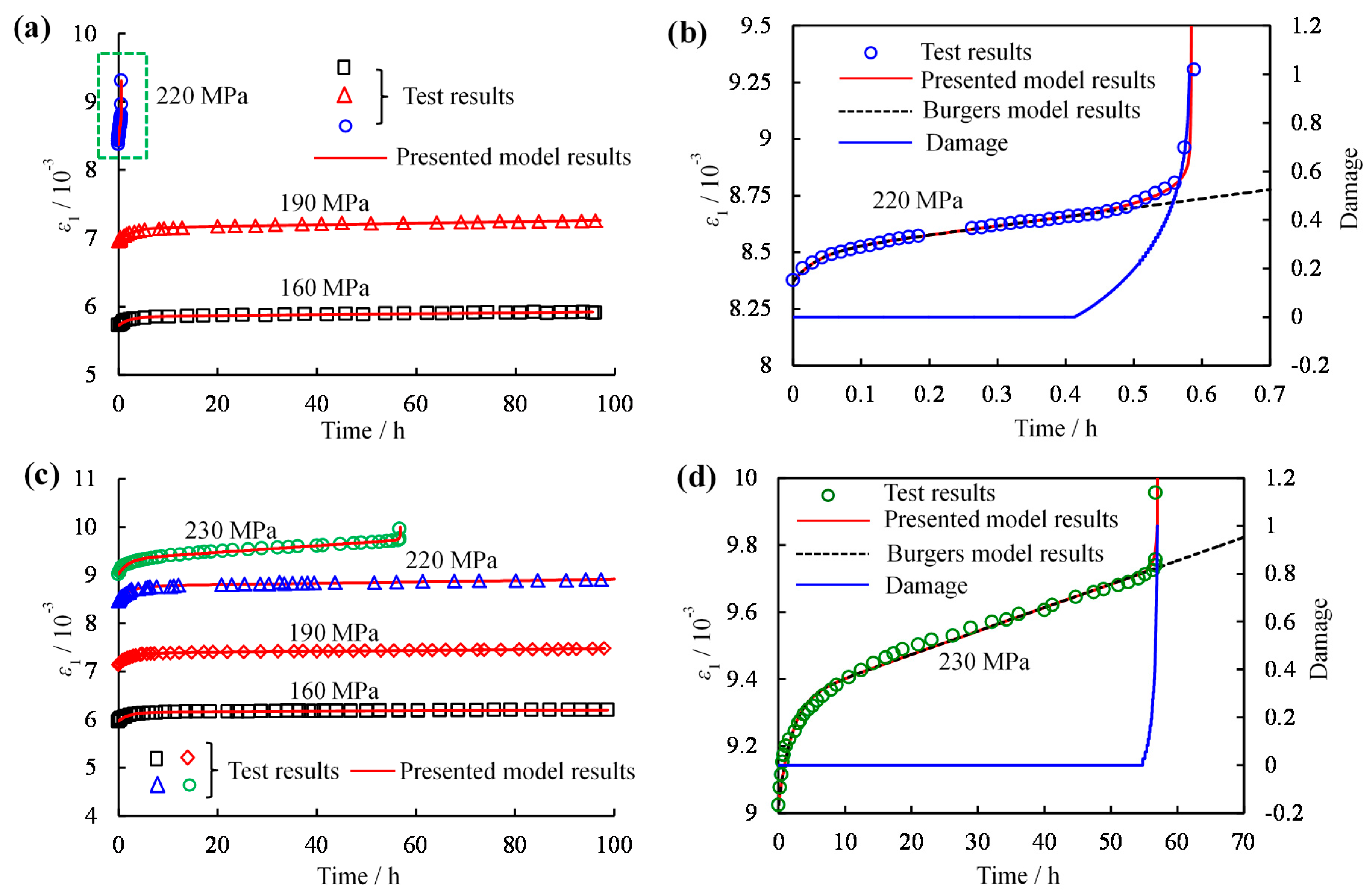
4.3. Model Validation

As mentioned earlier, the parameters of Burgers can be determined easily. We will next present a secondary development using FLAC3D (ITASCA Consulting China Ltd., Wuhan, China) to facilitate the calculations of α and U0. The damage constitution equation of Kelvin in FLAC3D can be written as:
S = e K G K ( D ) + e ˙ K η K ( D )
where S is the deviatoric stress, eK is the Kelvin partial strain, GK is the shear modulus of the Kelvin body, and ηK is the Kelvin viscosity coefficient. The difference expression of this equation can be written as:
e K N = e K O + ( S ¯ G K ( D ) e ¯ K ) Δ t η K ( D ) ,   and
S ¯ = S N + S O 2 ,   e ¯ K = e K N + e K O 2
where Δt is the creep time increment step, and SN and SO are the new and old deviatoric stresses of an increment step of creep time, respectively. Correspondingly, e K N and e K O are the new and old deviatoric strains of an increment step of creep time, respectively.
Similarly, the Maxwell damage constitution equation in FLAC3D can be written as:
e ˙ M = S ˙ G M ( D ) + S η M ( D )
where eM is the Maxwell partial strain, GM is the shear modulus of the Maxwell body, and ηM is the Maxwell viscosity coefficient. The difference expression of this equation can be written as
e M N = e M O + S N S O G M ( D ) + Δ t η M ( D ) S N + S O 2
where Δt is the increment step of creep time, and SN and SO are the new and old deviatoric stresses of an increment step of creep time, respectively. Correspondingly, e M N   and e M O are the new and old deviatoric strains of an increment step of creep time, respectively. In Burgers model, the difference of partial strain between new and old values can calculated as:
e N e O = e K N e K O + e M N e M O
The strain increment of the Kelvin body can be calculated using Equation (20):
e K N = 1 A [ B e K O + ( S N + S O ) Δ t 2 η K ( D ) ]
where:
A = 1 + G K ( D ) Δ t 2 η K ( D ) ,   and   B = 1 G K ( D ) Δ t 2 η K ( D )
Similarly, the strain increment of the Maxwell body can be calculated using Equation (22):
S N = 1 X [ ( e N e O ) ( B A 1 ) e K O + Y S O ]
where:
X = 1 G M ( D ) + Δ t 2 η M ( D ) + Δ t 2 η K ( D ) A ,   and   Y = 1 G M ( D ) Δ t 2 η M ( D ) Δ t 2 η K ( D ) A
In Equations (22) and (23), the increment of stress can be calculated according to the increment of strain. Numerical solutions can be obtained by satisfying all the boundary conditions on each side through multiple iterations.
The creep parameters can be deteriorated by introducing the cumulative damage variable after obtaining the linear difference equation of Burgers model. The strain energy in the creep process can be calculated using Equation (24):
U = t i = 1 3 S i N + S i O 2 ( e i N e i O )
It is supposed that there is no creep deformation or damage under conditions of hydrostatic pressure. Therefore, the creep parameters can be expressed as:
{ G M ( D ) = G M ( 1 D ) η M ( D ) = η M ( 1 D ) G K ( D ) = G K ( 1 D ) η K ( D ) = η K ( 1 D )
In view of the above discussions, the nonlinear creep damage model based on the Burgers model can be implemented through numerical simulations. The parameters of the Burgers model based on experimental data have been determined. Concretely speaking, U can be calculated according to the calculated parameters of the Burgers model by numerical simulation. U0 at the onset of tertiary creep based on tested data can then be determined from the numerical calculation results. Finally, α can be adjusted according to the experimentally characteristic of the accelerating creep based on experiment. The calculation and fitting results are shown in Table 2 and Figure 13.
From Figure 13, the creep damage model curves agree well with the experimental data, and the modified model is therefore reasonable and simple. According to Figure 13b,d, the Burgers and creep damage models produced the same fitting results during the primary and steady creep state stages. However, the creep damage model accurately reproduced the tertiary creep phase, whereas Burgers model was unable to describe the accelerated creep process when compared with the fitting results. In addition, as U increased above U0, D began to gradually increase from 0 to 1, which indicates that the dominant damage induced by cracks was augmented by creep deformation.

5. Discussion

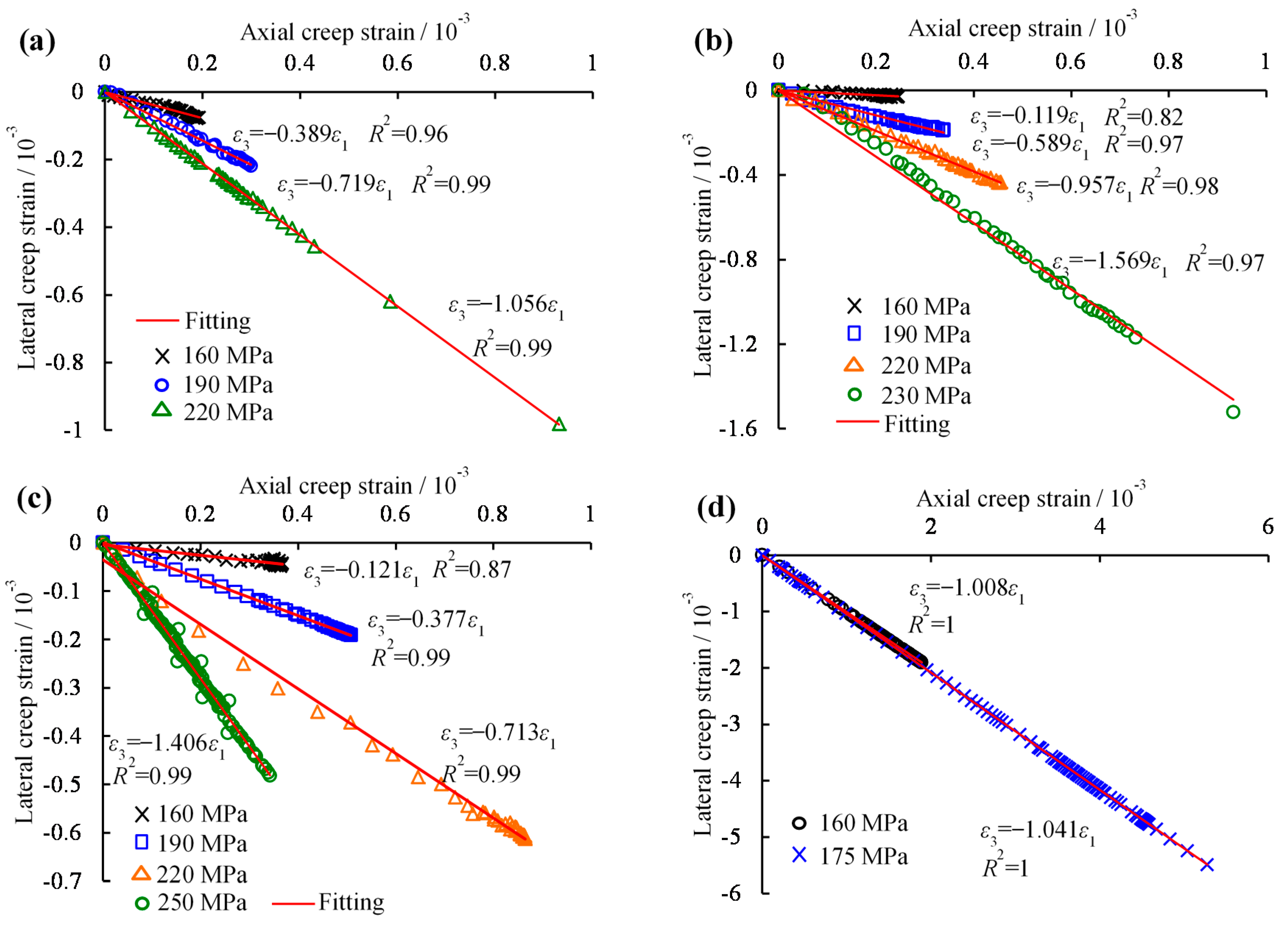
5.1. Relationship between the Axial and Lateral Creep Strain

Figure 14 shows the relations between the axial and the lateral creep strains from multi-stepping creep tests of specimens at various temperatures under a σ3 of 25 MPa. It is worth noting that a monotonic linear correlation between the axial and lateral creep strains could be determined for each stress condition. It should be emphasized that the negative sign represents the direction of lateral expansion. From Figure 14, the slopes of the fit lines increased gradually with increasing deviatoric stress, which means lateral deformation became more obvious as the deviatoric stress increased.
Comparing the slopes of the fit lines at different temperatures in Figure 14a–d, under a deviatoric stress of 160 MPa, the slope first decreased from 0.389 at 25 °C to 0.119 at 300 °C and then increased from 0.121 to 1.008 as the temperature was elevated from 700 °C to 1000 °C, as shown in Figure 14e. However, because the σp of the specimen at 1000 °C was the lowest (207.36 MPa), the specimen experienced creep rupture under a partial stress of 175 MPa. Therefore, the deformations under 190 MPa and 220 MPa could not be obtained, and the corresponding slope value also could not be calculated. As the temperature increased from room temperature to 700 °C, the slopes of the fit lines under deviatoric stresses of 190 and 220 MPa decreased linearly.

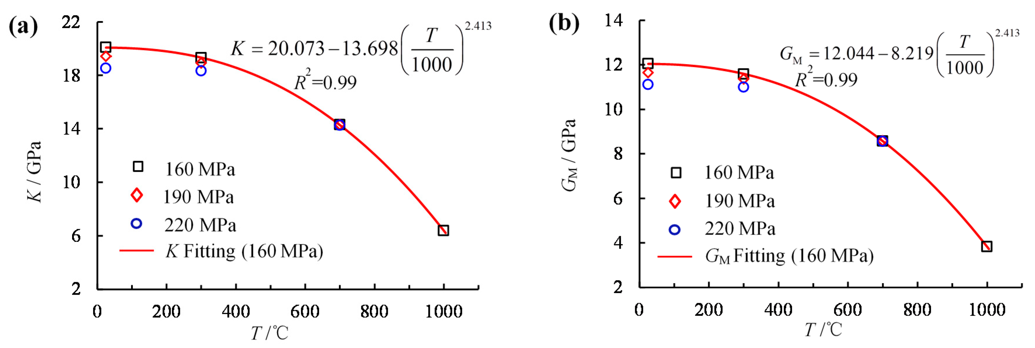
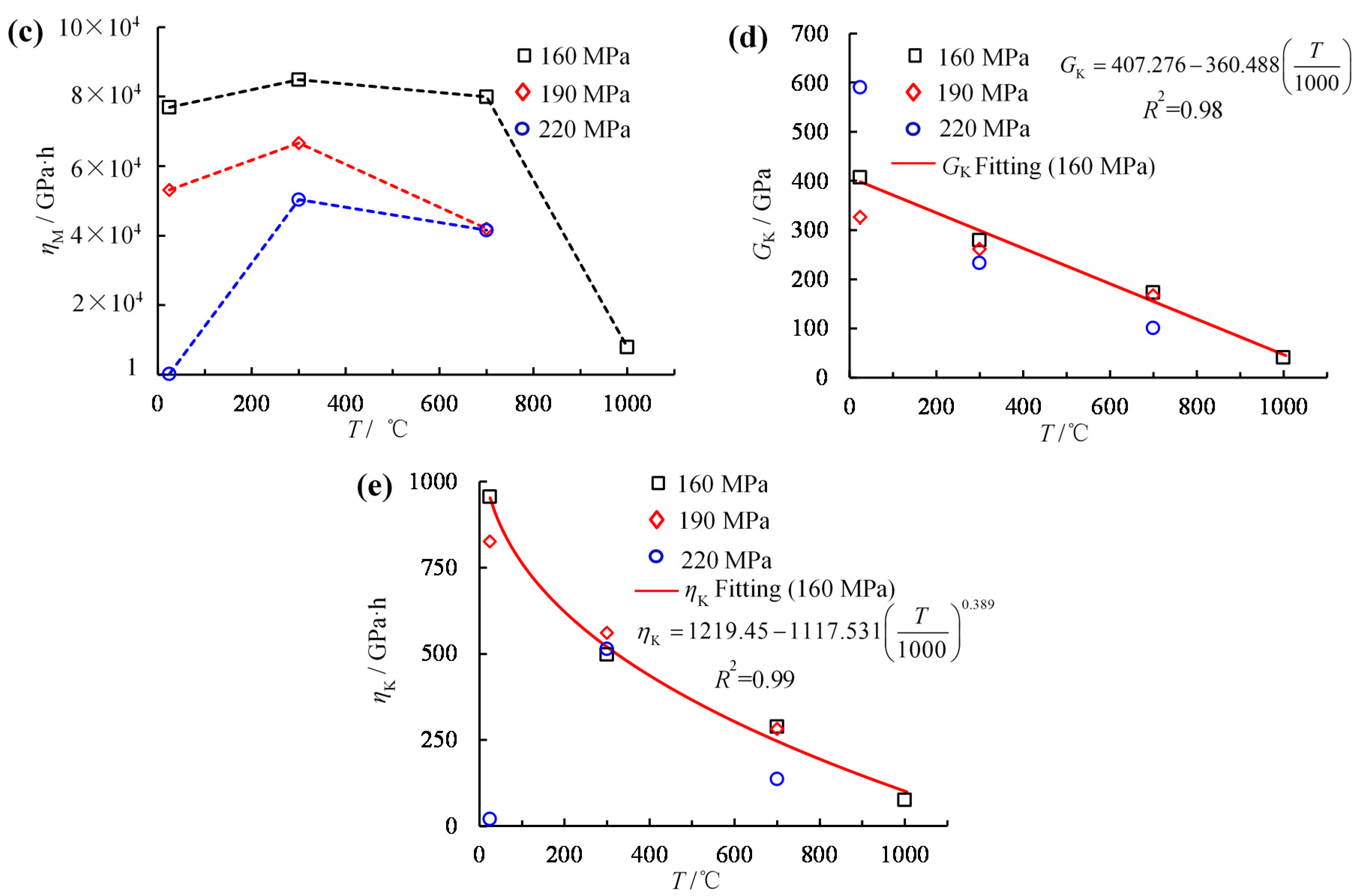
5.2. Thermal Influence on Parameters of Creep Model

This article mainly focusses the influence of temperature on creep deformation under same stress conditions. The presented creep damage model can also well describe the entire creep process. Therefore, it is necessary to discuss the influence of temperature on the creep parameters of the model under identical stress levels. Because the σc of each specimen differed at various temperatures, it is hard to fully consider the influence of temperature on creep parameters under each deviatoric stress. Accordingly, thermal effects on creep parameters can be investigated under common deviatoric stresses of 160, 190 and 220 MPa.
From Figure 15a, K decreased gradually with increasing temperature for specimens under 160, 190 and 220 MPa. It indicates that with increasing temperature, the variation in volume was more obvious under spherical stress (total stress can be divide into spherical stress and partial stress), the volume of material was changed by the spherical stress tensor, and the shape of the material was only changed by the differential stress tensor [65]. It is worth noting that the data used for this test were inadequate due to the specimens at 1000 °C under 190 and 220 MPa which were above their σp. Hence, the fits for the results from each specimen under 160 MPa are presented herein. Similarly, Figure 15b shows the variation in GM with temperature. K and GM showed the same trend because of the calculation using uniform E and μ according to the instantaneous axial strain. Those two parameters reflect instantaneous response when loading is applied, which is inversely proportional to the instantaneous strain. Figure 15c shows that the viscosity coefficient of the Maxwell body changed with temperature under the various stress levels. It first increased as the temperature rose to 300 °C and then decreased as the temperature rose above 300 °C. In particular, it suddenly decreased at 1000 °C under 160 MPa. This parameter reflects the state of steady creep and is strongly related to the ratio of applied stress and σp, which is proportional to the ratio. In Figure 15d, the shear modulus of the Kelvin body was linearly related to temperature, which decreased with increasing temperature. GK mainly affected the time from attenuation creep to steady-state creep. In Figure 15e, ηK decreased nonlinearly with increasing temperature, with the exception of the specimen at 25 °C under a σc of 220 MPa. This occurred because the specimens failed with large creep deformation in a short time. Furthermore, the viscosity coefficient of the Kelvin body mainly affected the instantaneous creep rate, which had an inversely proportion relationship.
Accordingly, the creep damage model considering thermal influence can be written as Equation (26) if the fitting relationships between the creep parameters and temperature can be obtained according to Equation (13):
ε 1 = ( σ 1 σ 3 ) + 3 σ 3 9 K ( T ) + ( σ 1 σ 3 ) 3 G M ( T ) ( 1 D ) + ( σ 1 σ 3 ) 3 G K ( T ) ( 1 D ) ( 1 exp ( G K ( T ) ( 1 D ) η K ( T ) ( 1 D ) t ) ) + ( σ 1 σ 3 ) 3 η M ( T ) ( 1 D ) t

5.3. Thermal Influence on Creep Behavior

High temperatures seriously deteriorate the degree of consolidation and amplified the distance between grains, especially via boundary and thermally-induced cracks. Therefore, the total amount of strain that can be accumulated increases with increasing temperature. It can explain the phenomenon whereby the instantaneous strain and time-based axial creep strain of red sandstone increased with increasing temperature under identical deviatoric stresses. The radius creep strain under same the stress conditions (e.g., deviatoric stresses of 160 and 190 MPa) first decreased as the temperature increased from 25 °C to 300 °C and then increased as temperature rose above 300 °C because the work due to the external force was mainly used for axial deformation, which was the main source of compression of the mineral particles and adjustment and closure of boundary cracks, and there was therefore little available work to induce lateral dilatancy deformation. As the temperature was increased to 700 °C, energy was required to close the thermally-induced cracks in addition to compressing the grains and closing the boundary cracks. Furthermore, the reduction in consolidation degree and ductility enhancement could have enhanced the degree of shear dilatancy, especially for the specimen at 1000 °C, whose bearing capacity decreased suddenly. When the applied stress (e.g., deviatoric stress = 160 MPa) exceeded its σcd, the axial bearing capacity was unable to consume much energy from the applied stress, so that the energy shifted to the lateral dilatancy part. Hence, its lateral creep strain showed large discrepancies when compared to the other thermal treated specimens. This can also explain the phenomenon whereby the volumetric creep strain shifted from axial compression-dominant to shear dilatancy-dominant as the temperature was increased. The volume creep strain mainly reflected the competing states of axial compression and lateral dilatancy.
Under increasing compressive stress, rock experiences differing degrees of nucleation, propagation, interaction and coalescence at various crack scale [67]. Hence, a specimen deforms promptly when different stresses are applied. While keeping the loading constant, the deformation will increase with increasing time on the basis of the former distortion. There are both elastic and viscous plastic deformations of the red sandstone matrix, and time-dependent microcrack propagation is generally coupled during the two processes. Another explanation is due to stress corrosion [60]. All of the above reasons promote the shear dilatancy deformation as stress level and time are increased.
Inspired by the form of normalized stress [30], herein termed the critical stress ratio (CSR), is expressed as:
CSR = σ c σ r σ p σ r
where σp is the peak strength, σr is the residual strength, and σc is the creep failure stress respectively.
From Figure 16, it can be seen that the critical stress ratio decreased with increasing temperature. To be specific, it decreased from 0.89 at room temperature to 0.44 at 1000 °C, and we can conclude that the temperature heavily affected the critical stress ratio, such that creep failure more easily occurred at higher temperatures. As the deviatoric stress increased to σc (reaching to the CSR), the specimen experienced failure sliding along a shear fault.

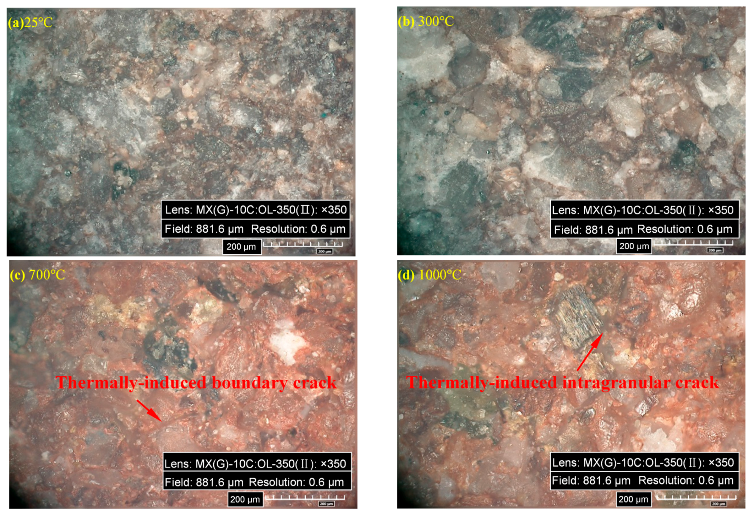
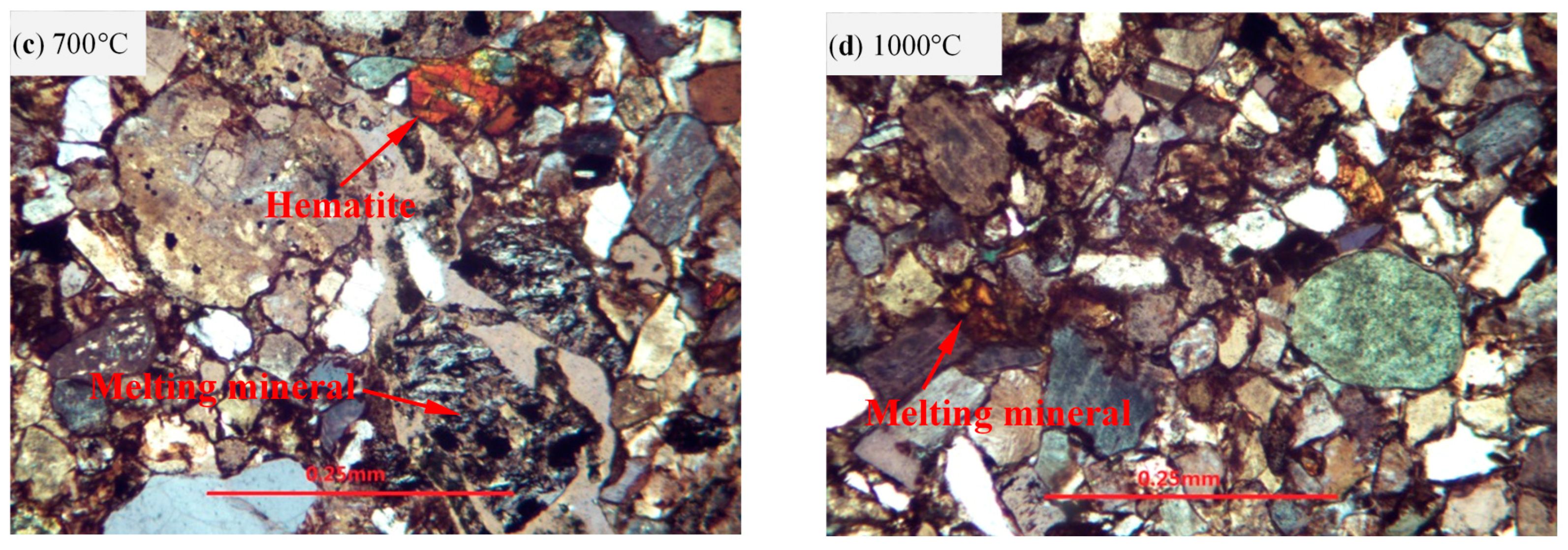
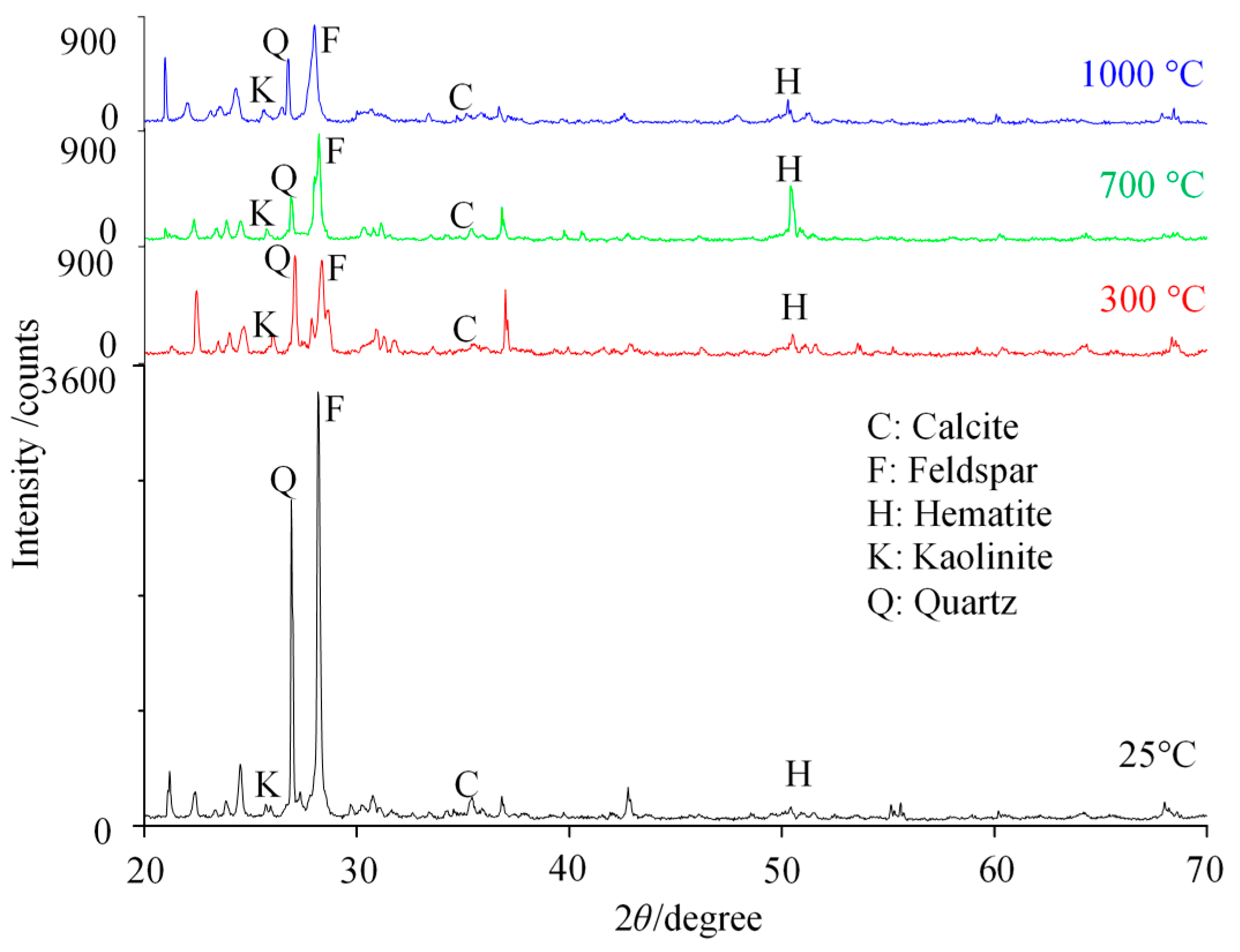
5.4. Thermal Influence on Microstructure/Composition

In order to analyze the microstructure and composition of specimens before and after heating, observation by optical and polarizing microscopy (Figure 17 and Figure 18) and X-ray diffraction (XRD) (Figure 19) were conducted after four temperatures (25, 300, 700 and 1000 °C) were applied. Figure 17 shows the microscopic structure of specimens after the different thermal treatments by optical microscopy. It is clear that the color variation of the specimen was marked, which varied from gray red to bright red, and then to reddish with increasing temperature. This indicated that mineral composition in specimens changed with the temperature. Moreover, thermally-induced cracks appeared at temperature above 700 °C, as shown in Figure 17c,d.
The main minerals in the tested red sandstone samples were recognized as feldspar, quartz, calcite, hematite and clay minerals. XRD spectra are plotted in Figure 19. The red sandstones showing reddish colors contain mostly a minor amount of ferrous minerals such as hematite. Hajpál and Török [68] reported that the color of sandstones depended on the mineral composition. As quartz is grey and most coloured (brownish-reddish) sandstones contain iron-bearing minerals. Therefore the colour changes in the specimens are related to the transformation of iron-bearing mineral phases at different temperatures. From Figure 19, not distinguishable change can be seen for the quart and feldspar, although the peaks for them decreased sharply as temperature at 300 °C. The kaolinite was becoming less and less with increasing temperature. The calcite disintegrated above 700 °C. Heap et al. [69] reported that the calcite started to decompose as temperature above 680 °C. Hajpál [70] reported that a new mineral phase of hematite appeared and goethite and jarosite disappeared at 900 °C. The hematite was the final reaction product of any iron-bearing oxy-hydroxide at high temperature. Figure 18 illustrates the microscopic structure of specimen after high-temperature treatments by polarizing microscopy. From Figure 18, as temperature increased by 700 °C and 1000 °C, hematite appeared and some minerals melted, which can explain the color variation of heated specimens.

6. Conclusions

The objective of this article was an investigation of the temperature influence on the creep behavior of red sandstone under a high confining pressure (σ3 = 25 MPa). Hence, a series of creep experiments was performed. The following conclusions are drawn:
(1)
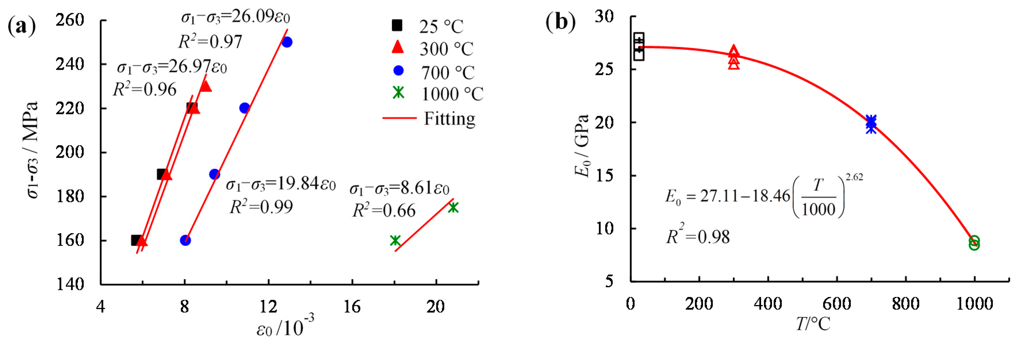
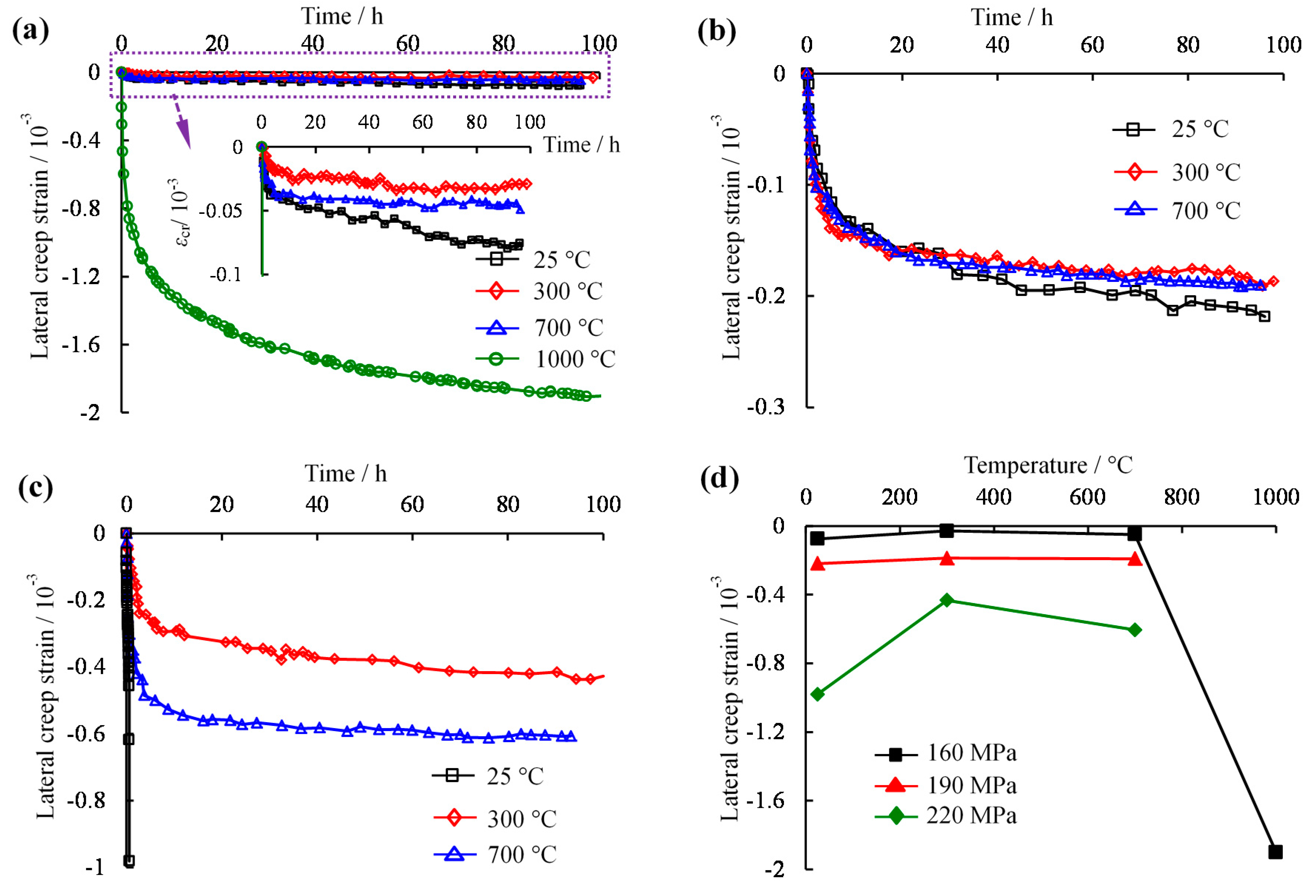
The axial instantaneous strain increased linearly with increasing partial stress at the same temperatures. As the deviatoric stress increased, both the lateral creep strain and the increment in the axial creep strain with time gradually rose, whereas the volumetric creep strain decreased from positive to negative values, which represented the initial compression, dilation, and finally failure by shear dilatancy of the specimens.
(2)
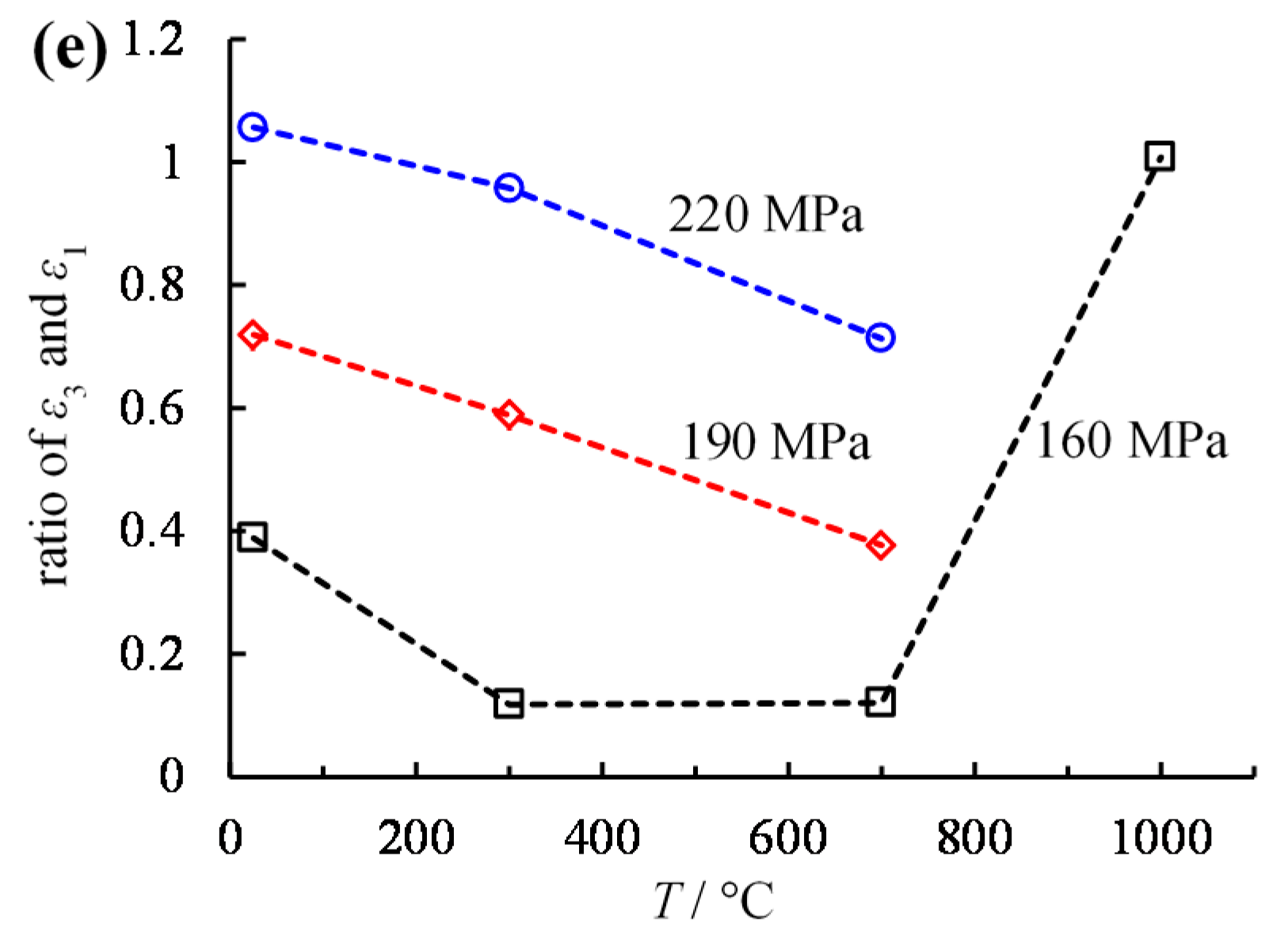
Under the same deviatoric stress and as the temperature was increased, the instantaneous deformation modulus (E0) decreased nonlinearly, the axial creep strain increased gradually, but the lateral creep strain first decreased when the temperature was below 300 °C and then increased when the temperature increased above 300 °C. The bulk expansion became easier as the applied stress approached σp. In addition, as the temperature increased, CSR decreased.
(3)
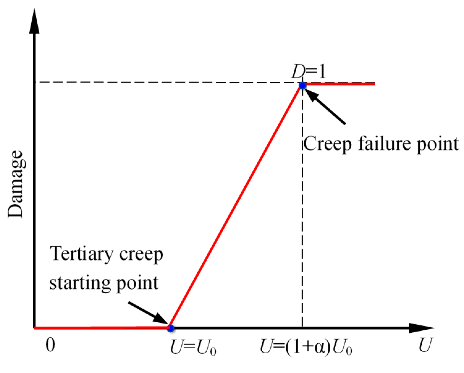
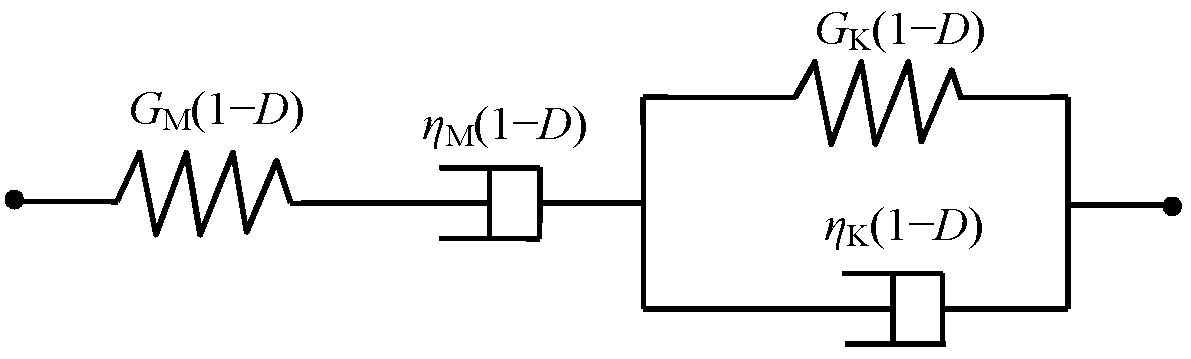
A creep damage model based on strain energy was established, and a secondary development was implemented in FLAC3D; the latter can effectively reproduce the entire creep process. In the model, the two damage parameters mainly affect the onset of tertiary creep and its duration.
(4)
The axial creep strain had an apparent linear relationship with the lateral creep strain. In addition, the slopes of fit lines increased gradually with increasing deviatoric stress. Under identical deviatoric stresses, the elastic parameters (K, GM and GK) and the viscosity coefficient (ηK) of the creep model decreased with temperature, whereas the viscosity coefficient (ηM) at first increased as the temperature rose to 300 °C and then decreased as temperature exceeded 300 °C.
(5)
Nevertheless, despite the preliminary experimental investigation of the thermal influence on the time-dependent behavior and creep damage model of red sandstone, more refined studies are necessary. In particular, further experimental work is essential to provide sufficient tests data to gain a deeper understanding of the mechanism of thermal effects. Furthermore, the coupled thermal and creep damage model requires study, verification and optimization.

Acknowledgments

The research was supported by the Natural Science Foundation of Jiangsu Province for Distinguished Young Scholars (BK20150005), National Natural Science Foundation of China (51734009) and the Fundamental Research Funds for the Central Universities (2015XKZD05). We would also like to acknowledge the editor and two anonymous reviewers for their valuable comments, which have greatly improved this paper.

Author Contributions

Sheng-Qi Yang conceived and designed the experiments; Bo Hu and Peng Xu performed the experiments; Sheng-Qi Yang and Bo Hu analyzed the data; Sheng-Qi Yang and Bo Hu wrote the paper, which was revised by Pathegama G. Ranjith.

Conflicts of Interest

The authors declare that they have no conflicts of interest.

List of Symbols

CSRCritical stress ratio
DDamage variable (0 ≤ D ≤ 1)
E0Instantaneous deformation modulus
GMShear modulus of Maxwell body
GKShear modulus of Kelvin body
KBulk modulus
PDifferencial stress (P = σ1σ3)
QThe sum of the least error square
R2The square of correlation coefficient
SDeviatoric stress
SijPartial stress tensor
Se, Sv, SvePartial stress tensors on elastic, viscosity and visco-elastic portions
SNNew deviatoric stress for a time step
Old deviatoric stress for a time step
The derivative of S
TTemperature
tCreep time
t0Beginning time of accelerating creep
UdDissipation energy
U 0 d Dissipation energy corresponding to the initial damage
UStrain energy
U0Critical strain energy

Greek Symbols

σ1, σ2, σ3Principle stresses (σ1σ3 = σ2 compression positive)
σijStress tensor
σpTriaxial peak strength
σcdTriaxial damage stress
σrTriaxial residual strength
σcCreep failure stress
σmSpheric stress
εijStrain tensor
εmSpheric strain
ε0Instantaneous axial strain
εcrCreep strain
eijPartial strain tensor
ee, ev, evePartial strain tensors of elastic, viscosity and visco-elastic portions
ėKPartial strain rate of Kelvin body
eKPartial strain of Kelvin body
eMPartial strain of Maxwell body
eNNew deviatoric strain for a time step
Old deviatoric strain for a time step
e K N New deviatoric strain for a time step of Kelvin body
e K O Old deviatoric strain for a time step of Kelvin body
e M N New deviatoric strain for a time step of Maxwell body
e M O Old deviatoric strain for a time step of Maxwell body
ΔtIncrement step of creep time
ηMViscosity coefficient of Maxwell body
ηKViscosity coefficient of Kelvin body
μPoisson’s ratio
αParameter related to the material
βParameter related to the material
Ω0Initial creep parameter
ΩcdCreep parameter rafter creep damage

References

  1. Yang, S.Q.; Ranjith, P.G.; Jing, H.W.; Tian, W.L.; Ju, Y. An experimental investigation on thermal damage and failure mechanical behavior of granite after exposure to different high temperature treatments. Geothermics 2017, 65, 180–197. [Google Scholar] [CrossRef]
  2. Yang, S.Q.; Xu, P.; Li, Y.B.; Huang, Y.H. Experimental investigation on triaxial mechanical and permeability behavior of sandstone after exposure to different high temperature treatments. Geothermics 2017, 69, 93–109. [Google Scholar] [CrossRef]
  3. Zhao, Y.S.; Wan, Z.J.; Kang, J.R. Introduction to Geothermal Extraction of Hot Dry Rock; Sciences Press: Beijing, China, 2004; pp. 9–18. [Google Scholar]
  4. Yang, S.Q.; Tian, W.L.; Huang, Y.H. Failure mechanical behavior of pre-holed granite specimens after elevated temperature treatment by particle flow code. Geothermics 2018, 72, 124–137. [Google Scholar] [CrossRef]
  5. Stiegel, G.J.; Ramezan, M. Hydrogen from coal gasification: An economical pathway to a sustainable energy future. Int. J. Coal Geol. 2006, 65, 173–190. [Google Scholar] [CrossRef]
  6. Ranjith, P.G.; Daniel, R.V.; Chen, B.J.; Perera, M.S.A. Transformation plasticity and the effect of temperature on the mechanical behaviour of Hawkesbury sandstone at atmospheric pressure. Eng. Geol. 2012, 151, 120–127. [Google Scholar]
  7. Yang, S.Q.; Tian, W.L.; Ranjith, P.G. Experimental investigation on deformation failure characteristics of crystalline marble under triaxial cyclic loading. Rock. Mech. Rock Eng. 2017, 50, 2871–2889. [Google Scholar] [CrossRef]
  8. Voight, B. Structural stability of andesite volcanoes and lava domes. Philos. Trans. R. Soc. A 2000, 358, 1663–1703. [Google Scholar] [CrossRef]
  9. Watters, R.J.; Zimbelman, D.R.; Bowman, S.D.; Crowley, J.K. Rock mass strength assessment and significant to edifice stability, Mt Rainer and Mt Hood, Cascade Range volcanoes. Pure Appl. Geophys. 2005, 157, 957–976. [Google Scholar] [CrossRef]
  10. Heap, M.J.; Baud, P.; Meredith, P.G. The influence of temperature on brittle creep in sandstones. Geophys. Res. Lett. 2009, 36, L19305. [Google Scholar] [CrossRef]
  11. Heap, M.J.; Baud, P.; Meredith, P.G.; Vinciguerra, S.; Bell, A.F.; Main, I.G. Brittle creep in basalt and its application to time-dependent volcano deformation. Earth Planet Sci. Lett. 2011, 307, 71–82. [Google Scholar] [CrossRef]
  12. Logan, S.E. Deep self-burial of radioactive wastes by rock-melting capsules. Nucl. Technol. 1974, 21, 111–124. [Google Scholar] [CrossRef]
  13. Heuze, F.E. On the Geotechnical Modelling of High-Level Nuclear Waste Disposal by Rock Melting; UCRL-53183; Lawrence Livermore Laboratory: Livermore, CA, USA, 1981.
  14. Gibb, S.E. High-temperature, very deep geological disposal: A safer alternative for high-level radioactive waste? Waste Manag. 1999, 19, 207–211. [Google Scholar] [CrossRef]
  15. Qin, B.D.; Chen, L.J.; Liu, X. Experimental research on the swelling stresses in limestone at high temperatures. J. China Univ. Min. Technol. 2009, 38, 326–330. [Google Scholar]
  16. Michalski, S.R. The jharia mine fire control technical assistance project: An analysis. Int. J. Coal Geol. 2004, 59, 83–90. [Google Scholar] [CrossRef]
  17. Otto, C.; Kempka, T. Thermo-mechanical simulations of rock behavior in underground coal gasification show negligible impact of temperature dependent parameters on permeability changes. Energies 2015, 8, 5800–5827. [Google Scholar] [CrossRef]
  18. Goetze, C.; Brace, W.F. Laboratory observations of high-temperature rheology of rocks. Tectonophysics 1972, 13, 583–600. [Google Scholar] [CrossRef]
  19. Weertman, J.; Weertman, J.R. High temperature creep of rock and mantle viscosity. Annu. Rev. Earth Planet Sci. 1975, 3, 293–315. [Google Scholar] [CrossRef]
  20. Post, R.L. High temperature creep of Mt. Burnet dunite. Tectonophysics 1977, 42, 75–110. [Google Scholar] [CrossRef]
  21. Zhou, Y.S.; He, C.R.; Huang, X.G.; Song, J.; Sang, Z. Rheological complexity of mafic rocks and effect of mineral component on creep of rocks. Earth Sci. Front. 2009, 16, 76–87. [Google Scholar]
  22. Chen, L.; Wang, C.P.; Liu, J.F.; Li, Y.; Liu, J.; Wang, J. Effects of temperature and stress on the time-dependent behavior of Beishan granite. Int. J. Rock Mech. Min. Sci. 2017, 93, 16–323. [Google Scholar] [CrossRef]
  23. Lipponen, A.; Manninen, S.; Niini, H.; Ro, E. Effect of water and geological factors on the long-term stability of fracture zones in the Päijänne Tunnel, Finland: A case study. Int. J. Rock Mech. Min. Sci. 2005, 42, 3–12. [Google Scholar] [CrossRef]
  24. Cao, P.; Wan, L.H.; Wang, Y.X.; Huang, Y.H.; Zhang, X.Y. Viscoelasto-plastic properties of deep hard rocks under water environment. Trans. Nonferrous Met. Soc. China 2011, 21, 2711–2718. [Google Scholar] [CrossRef]
  25. Yang, S.Q.; Jing, H.W.; Cheng, L. Influences of pore pressure on short-term and creep mechanical behavior of red sandstone. Eng. Geol. 2014, 179, 10–23. [Google Scholar] [CrossRef]
  26. Tsai, L.S.; Hsieh, Y.M.; Weng, M.C.; Huang, T.H.; Jeng, F.S. Time-dependent deformation behaviors of weak sandstones. Int. J. Rock Mech. Min. Sci. 2008, 45, 144–154. [Google Scholar] [CrossRef]
  27. Heap, M.J.; Baud, P.; Meredith, P.G.; Bell, A.F.; Main, I.G. Time-dependent brittle creep in Darley Dale sandstone. J. Geophys. Res. 2009, 114, 4288–4309. [Google Scholar] [CrossRef]
  28. Yang, D.S.; Chen, L.F.; Yang, S.Q. Experimental investigation of the creep and damage behavior of Linyi red sandstone. Int. J. Rock Mech. Min. Sci. 2014, 72, 164–172. [Google Scholar] [CrossRef]
  29. Maranini, E.; Brignoli, M. Creep behaviour of a weak rock: Experimental characterization. Int. J. Rock Mech. Min. Sci. 1999, 36, 127–138. [Google Scholar] [CrossRef]
  30. Brantut, N.; Heap, M.J.; Meredith, P.G.; Baud, P. Time-dependent cracking and brittle creep in crustal rocks: A review. J. Struct. Geol. 2013, 52, 17–43. [Google Scholar] [CrossRef]
  31. Cristescu, N. Rock Rheology; Kluwer Academic: Dordrecht, The Netherlands, 1989. [Google Scholar]
  32. Chopra, P.N. High-temperature transient creep in olivine rocks. Tectonophysics 1997, 279, 93–111. [Google Scholar] [CrossRef]
  33. Ferrero, A.M.; Marini, P. Technical note experimental studies on the mechanical behavior of two thermal cracked marbles. Rock Mech. Rock Eng. 2001, 34, 57–66. [Google Scholar] [CrossRef]
  34. Du, S.J.; Liu, H.; Zhi, H.T.; Chen, H.H. Testing study on mechanical properties of post-high-temperature granite. Chin. J. Rock Mech. Eng. 2004, 23, 2359–2364. (In Chinese) [Google Scholar]
  35. Brotóns, V.; Tomás, R.; Ivorra, S.; Alarcón, J.C. Temperature influence on the physical and mechanical properties of a porous rock: San Julian’ calcarenite. Eng. Geol. 2013, 167, 117–127. [Google Scholar] [CrossRef]
  36. Tian, H.; Kempka, T.; Xu, N.X.; Ziegler, M. Physical properties of sandstones after high temperature. Rock Mech. Rock. Eng. 2012, 45, 1113–1117. [Google Scholar] [CrossRef]
  37. Tian, H.; Kempka, T.; Yu, S.; Ziegler, M. Mechanical properties of sandstones exposed to high temperature. Rock Mech. Rock. Eng. 2016, 49, 321–327. [Google Scholar] [CrossRef]
  38. Tian, H.; Ziegler, M.; Kempka, T. Physical and mechanical behavior of claystone exposed to temperature up to 1000 °C. Int. J. Rock Mech. Min. Sci. 2014, 70, 144–153. [Google Scholar] [CrossRef]
  39. Li, M.; Mao, X.B.; Cao, L.L.; Mao, R.R.; Tao, J. Experimental study of mechanical properties on strain rate effect of sandstones after high temperature. Chin. Rock Soil. Mech. 2014, 23, 3479–3488. [Google Scholar]
  40. Ye, G.L.; Nishimura, T.; Zhang, F. Experimental study on shear and creep behaviour of green tuff at high temperatures. Int. J. Rock Mech. Min. Sci. 2015, 79, 19–28. [Google Scholar] [CrossRef]
  41. Sun, Q.; Lü, C.; Cao, L.W.; Li, W.C.; Geng, J.S.; Zhang, W.Q. Thermal properties of sandstone after treatment at high temperature. Int. J. Rock Mech. Min. Sci. 2016, 85, 60–66. [Google Scholar] [CrossRef]
  42. Carter, N.L.; Horseman, S.T.; Russell, J.E.; Handin, J. Rheology of rock-salt. J. Struct. Geol. 1993, 15, 1257–1271. [Google Scholar] [CrossRef]
  43. Main, I.G. A damage mechanics model for power-law creep and earthquake aftershock and foreshock sequences. Geophys. J. Int. 2000, 142, 151–161. [Google Scholar] [CrossRef]
  44. Burgers, J.M. Mechanical Considerations-Model Systems-Phenomenological Theories of Relaxation and of Viscosity; Nordemann Publishing Company: New York, NY, USA, 1935. [Google Scholar]
  45. Fahimifar, A.; Tehrani, F.M.; Hedayat, A.; Vakilazdeh, A. Analytical solution for the excavation of circular tunnels in a visco-elastic Burger’s material under hydrostatic stress field. Tunn. Undergr. Space Technol. 2010, 25, 297–304. [Google Scholar] [CrossRef]
  46. Zhao, Y.L.; Wang, Y.X.; Wang, W.J.; Tang, J.Z. Modeling of non-linear rheological behavior of hard rock using triaxial rheological experiment. Int. J. Rock Mech. Min. Sci. 2017, 93, 66–75. [Google Scholar] [CrossRef]
  47. Valanis, K.C. Theory of viscoplasticity without a yield surface Part.1. Gen. Theory Arch. Mech. 1971, 23, 517. [Google Scholar]
  48. Yang, C.H.; Wang, W.L.; Fan, J.H. A kind of endochronic constitutive description of mechanical properties of soft rock under static loading. Rock Soil Mech. 1987, 8, 11–17. (In Chinese) [Google Scholar]
  49. Abu Al-Rub, R.K.; Darabi, M.K. A thermodynamic framework for constitutive modeling of time- and rate-dependent materials. Part I: Theory. Int. J. Plast. 2012, 34, 61–92. [Google Scholar] [CrossRef]
  50. Xie, H.P.; Peng, R.D.; Ju, Y. Energy dissipation of rock deformation and fracture. Chin. J. Rock Mech. Eng. 2004, 23, 3565–3570. (In Chinese) [Google Scholar]
  51. Yoshida, H.; Horii, H. A micromechanics-based model for creep behavior of rock. Appl. Mech. Rev. 1992, 45, 294–303. [Google Scholar] [CrossRef]
  52. Lu, Y.L.; Elswort, D.; Wang, L.G. A dual-scale approach to model time-dependent deformation, creep and fracturing of brittle rocks. Comput. Geotech. 2014, 60, 61–76. [Google Scholar] [CrossRef]
  53. Shao, J.F.; Chau, K.T.; Feng, X.T. Modeling of anisotropic damage and creep deformation in brittle rocks. Int. J. Rock Mech. Min. Sci. 2006, 43, 582–592. [Google Scholar] [CrossRef]
  54. Kachanov, L.M. Time of the rupture process under creep conditions. Izv. Akad. Nauk S S R Otd. Tech. Nauk 1958, 8, 26–31. [Google Scholar]
  55. Lemaitre, J. Evaluation of dissipation and damage in metals under dynamic loading. In Proceedings of the International Congress on Mechanical Behavior of Materials (ICM), Kyoto, Japan, August 1971. [Google Scholar]
  56. Murakami, S. Notion of Continuum Damage Mechanics and Its Application to Anisotropic Creep Damage Theory. J. Eng. Mater. Technol. 1983, 105, 99–105. [Google Scholar] [CrossRef]
  57. Kyoya, T. A damage mechanics theory for discontinuous rock mass. In Proceedings of the Fifth International Conference on Numerical Methods in Geomechanics, Nagoya, Japan, 1–5 April 1985; pp. 469–480. [Google Scholar]
  58. Lockner, D.; Byerlee, J. Acoustic emission and creep in rocks at high confining pressure and differential stress. Bull. Seismol. Soc. Am. 1977, 67, 247–258. [Google Scholar]
  59. Baud, P.; Meredith, P.G. Damage accumulation during triaxial creep of Darley Dale sandstone from pore volumometry and acoustic emission. Int. J. Rock Mech. Min. Sci. 1997, 34, 24.e1–24.e10. [Google Scholar] [CrossRef]
  60. Atkinson, B.K. Subcritical crack growth in geological materials. J. Geophys. Res. 1984, 89, 4077–4114. [Google Scholar] [CrossRef]
  61. Meredith, P.G.; Atkinson, B.K. Stress corrosion and acoustic emission during tensile crack propagation in Whin Sill dolerite and other basic rocks. Geophys. J. Int. 1983, 75, 1–21. [Google Scholar] [CrossRef]
  62. Yang, S.Q.; Xu, P.; Ranjith, P.G. Damage model of coal under creep and triaxial compression. Int. J. Rock Mech. Min. Sci. 2015, 80, 337–345. [Google Scholar] [CrossRef]
  63. Xie, H.P.; Li, L.; Peng, R.; Ju, Y. Energy analysis and criteria for structural failure of rocks. J. Rock Mech. Geotech. Eng. 2009, 1, 11–20. [Google Scholar] [CrossRef]
  64. Lin, Q.X.; Liu, Y.M.; Tham, L.G.; Tang, C.A.; Lee, P.K.K.; Wang, J. Time-dependent strength degradation of granite. Int. J. Rock Mech. Min. Sci. 2009, 46, 1103–1114. [Google Scholar] [CrossRef]
  65. Yu, T.Q.; Wang, X.W.; Liu, Z.H. Elasticity and Plasticity; China Architecture and Building Press: Beijing, China, 2004. [Google Scholar]
  66. Sun, J. Rheological Behavior of Geomaterials and Its Engineering Applications; China Architecture and Building Press: Beijing, China, 1999. [Google Scholar]
  67. Wong, T.F. Effects of temperature and pressure on failure and post-failure behavior of Westerly granite. Mech. Mater. 1982, 1, 3–17. [Google Scholar] [CrossRef]
  68. Hajpál, M.; Török, Á. Mineralogical and colour changes of quartz sandstones by heat. Environ. Geol. 2004, 46, 311–322. [Google Scholar] [CrossRef]
  69. Heap, M.J.; Mollo, S.; Vinciguerra, S. Thermal weakening of the carbonate basement under Mt. Etna volcano (Italy): Implications for volcano instability. J. Volcanol. Geotherm. Res. 2013, 250, 42–60. [Google Scholar] [CrossRef]
  70. Hajpál, M. Changes in Sandstones due to Thermal Effect. Unpublished Ph.D. Thesis, Budapest University of Technology and Economics, Budapest, Hungary, 2002. (In Hungarian with English and German Abstract). [Google Scholar]
Figure 1. Loading procedure for creep tests.
Energies 11 00212 g001
Figure 2. (a) Relation between the axial instantaneous strain and deviator stress and (b) Relation between the instant deformation modulus and temperature.
Energies 11 00212 g002
Figure 3. Axial creep strain-time curves under step-loading with σ3 of 25 MPa at different temperatures: (a) 25 °C; (b) 300 °C; (c) 700 °C; (d) 1000 °C; (e) Relationship between axial creep strain and deviatoric stress.
Energies 11 00212 g003
Figure 4. Axial creep strain-time curves under identical stress level at different temperatures (σ3 = 25 MPa): (a) σ1σ3 = 160 MPa; (b) σ1σ3 = 190 MPa; (c) σ1σ3 = 220 MPa; (d) Relationship between axial creep strain and temperature.
Energies 11 00212 g004
Figure 5. Lateral creep strain-time curves under step-loading at different temperatures (σ3 = 25 MPa): (a) 25 °C; (b) 300 °C; (c) 700 °C; (d) 1000 °C; (e) Relationship between lateral creep strain and deviatoric stress.
Energies 11 00212 g005
Figure 6. Lateral creep strain-time curves under same stress condition at different temperatures (σ3 = 25 MPa): (a) σ1σ3 = 160 MPa; (b) σ1σ3 = 190 MPa; (c) σ1σ3 = 220 MPa; (d) Relationship between lateral creep and temperature.
Energies 11 00212 g006
Figure 7. Volumetric creep strain-time curves under step-loading at different temperatures (σ3 = 25 MPa): (a) 25 °C; (b) 300 °C; (c) 700 °C; (d) 1000 °C; (e) Relationship between volumetric creep strain and deviatoric stress.
Energies 11 00212 g007aEnergies 11 00212 g007b
Figure 8. Relations of volumetric creep strain-time curves and temperature under identical stress condition (σ3 = 25 MPa): (a) σ1σ3 = 160 MPa; (b) σ1σ3 = 190 MPa; (c) σ1σ3 = 220 MPa; (d) Relationship between volumetric creep strain and temperature.
Energies 11 00212 g008
Figure 9. Rock damage evolution trend.
Energies 11 00212 g009
Figure 10. Rock creep damage model and Burgers model.
Energies 11 00212 g010
Figure 11. Creep damage model of Burgers.
Energies 11 00212 g011
Figure 12. Influence of U0 and α to strain curve and damage: (a) α = 0.03; (b) U0 = 1.33 × 10⁶ (Note: K = 10 GPa, GM = 10 GPa, GK = 250 GPa, ηM = 10,000 GPa·h and ηK = 500 GPa·h).
Energies 11 00212 g012
Figure 13. Comparison between the modeling and experimental results under confining of 25 MPa: (a) 25 °C; (b) partial enlarged for σ1σ3 = 220 MPa; (c) 300 °C; (d) partial enlarged for σ1σ3 = 230 MPa.
Energies 11 00212 g013
Figure 14. Relationships between the axial creep strain and the lateral creep strain at different temperatures: (a) 25 °C; (b) 300 °C; (c) 700 °C; (d) 1000 °C; (e) Relation between the slope of fitting line and temperature.
Energies 11 00212 g014aEnergies 11 00212 g014b
Figure 15. Relation between creep parameters and temperature: (a) K; (b) GM; (c) ηM; (d) GK; (e) ηK.
Energies 11 00212 g015aEnergies 11 00212 g015b
Figure 16. Critical stress ratio versus temperature.
Energies 11 00212 g016
Figure 17. Microscopic structure of red sandstone (optical microscopy) used in this research.
Energies 11 00212 g017
Figure 18. Microscopic structure of red sandstone (polarizing microscopy) used in this research.
Energies 11 00212 g018aEnergies 11 00212 g018b
Figure 19. XRD spectra for the powder of sandstone after different thermal treatments.
Energies 11 00212 g019
Table 1. Strength parameters of tested samples.
T/°Cσ3/MPaσS/MPaσp/MPaσcd/MPaES/GPaE50/GPa
2525259.32234.32223.3426.1328.65
30025269.78244.78228.3228.4228.77
70025316.29291.29263.5325.4921.23
100025232.36207.36132.9910.497.84
Note: σS = σp + σ3; σp: the peak strength; σcd: the crack damage stress; ES: the elastic modulus (the even slope of the approximately straight line portion); E50: the secant modulus (the slope between the start point and the stress at a half of peak strength).
Table 2. Parameters of creep damage model in creep tests (σ3 = 25 MPa).
T/°CP/MPaP/σp/%K/GPaGM/GPaηM × 103/GPa·hGK/GPaηK/GPa·hαU0/J mm−1R2Q × 10−3
251606820.0912.0576.93407.09956.58 0.991.53
1908119.4111.6453.19325.88826.49 0.993.31
2209418.5111.110.18590.2021.540.0659.86 × 1050.9810.32
3001606519.3011.5884.83279.28498.57 0.991.03
1907818.9211.3566.63260.97561.20 0.991.37
2209018.3310.9950.37232.90514.73 0.995.82
2309417.9210.7510.96247.73494.990.031.024 × 1060.9814.54
7001605514.298.5779.98172.57289.35 0.997.28
1906514.298.5841.99166.80282.35 0.982.36
2207614.258.5541.56100.77137.15 0.985.39
1000160776.373.820.7940.1877.37 0.983.67
Note: μ = 0.25; P: deviatoric stress.

