1. Introduction
Taiwan’s first and second nuclear power plants use boiling water reactors (BWRs) constructed by General Electric Corporation (Boston, MA, USA). In accordance with the practices abroad, the Taiwan Power Company (Taipower, Taiwan) built dry storage facilities at its nuclear power plants. After using the nuclear fuel for many years, Taipower removed the spent fuel from the reactor cores, cooled it in pools, and then stored the spent fuel in dry storage facilities to ensure that the plants had sufficient space in which to operate. Currently, the dry storage facility at nuclear power plant no. 1 has been tested. The safety review of the dry storage facilities of nuclear power plant no. 2 has also been completed.
There are few studies regarding the heat transfer performance of dry spent fuel storage casks. Xie et al. [
1] numerically investigated natural convection heat transfer in a horizontally placed dry spent fuel storage cask. Pugliese et al. [
2] evaluated the integrity of a spent fuel cask under both normal and accident scenario transport conditions, such as impact and fire events, according to the International Atomic Energy Agency (IAEA) accident test requirements. Koga and Tominaga [
3] investigated characteristic cooling flow in the annular gap of a concrete cask used to store spent nuclear fuel via a simplified test model. Li and Liu [
4] studied the thermal performance of a vertical dry storage cask with a welded canister containing high-burnup fuel. Kim et al. [
5] investigated heat transfer in a concrete cask like the one used at the intermediate storage facilities for BWR spent fuel.
Thermal modeling of the temperature profiles of dry casks was identified as a high-priority task in a U.S. Department of Energy gap analysis. In this work, a two-dimensional thermal model of a vertical dry cask is established via a computational fluid dynamics (CFD) simulation.
2. Research Methods
2.1. Dry Storage Cask
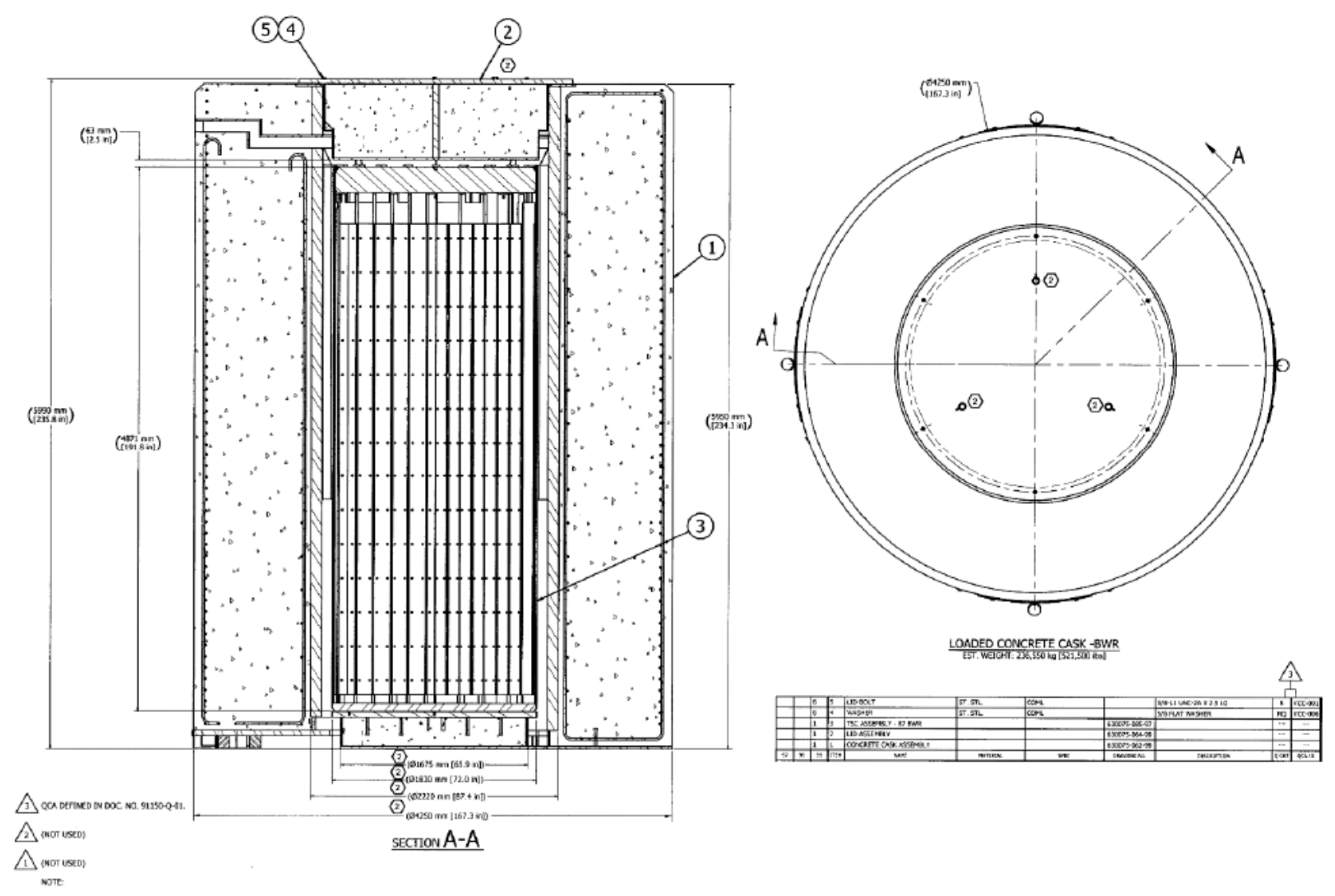
Dry storage casks are used to store spent nuclear fuel from nuclear power plants. Such casks primarily consist of a nuclear waste steel canister, a concrete cask and a transportation cask. In this paper, the investigated model is based on the dry storage cask in NAC’s (NAC International Inc., Norcross, GA, USA) MAGNASTOR-87, as shown in
Figure 1 (Taiwan Power Company [
6]).
2.2. The Investigated Model
Figure 2a shows a diagram of the model used in numerical simulations in this study. This model is simplified from
Figure 1. Inside the cask, there is a steel canister containing spent nuclear fuel (symbol ➊). The canister diameter is 1.8 m, and the height is 5 m. The concrete cask surrounding the steel canister has a thickness of approximately 1 m (➋). A flow channel (➌) of width 10 cm is located between the steel canister and concrete cask. The decay heat of the nuclear fuel heats the air in the channel. The heated air rises to the channel exit because of the buoyancy effect (➍) and exits the dry storage cask. The external air enters the channel from the bottom (➎) and forms a natural ventilation path (➏). In addition to the thermal buoyancy ventilation, the ventilation of the dry storage cask by external wind is also considered. It should be noted that when the two natural ventilation airflows (airflows induced by buoyancy and wind) conflict, the thermal dissipation performance of the dry storage cask can decrease. This study does not discuss this topic, and it will be addressed in follow-up studies.
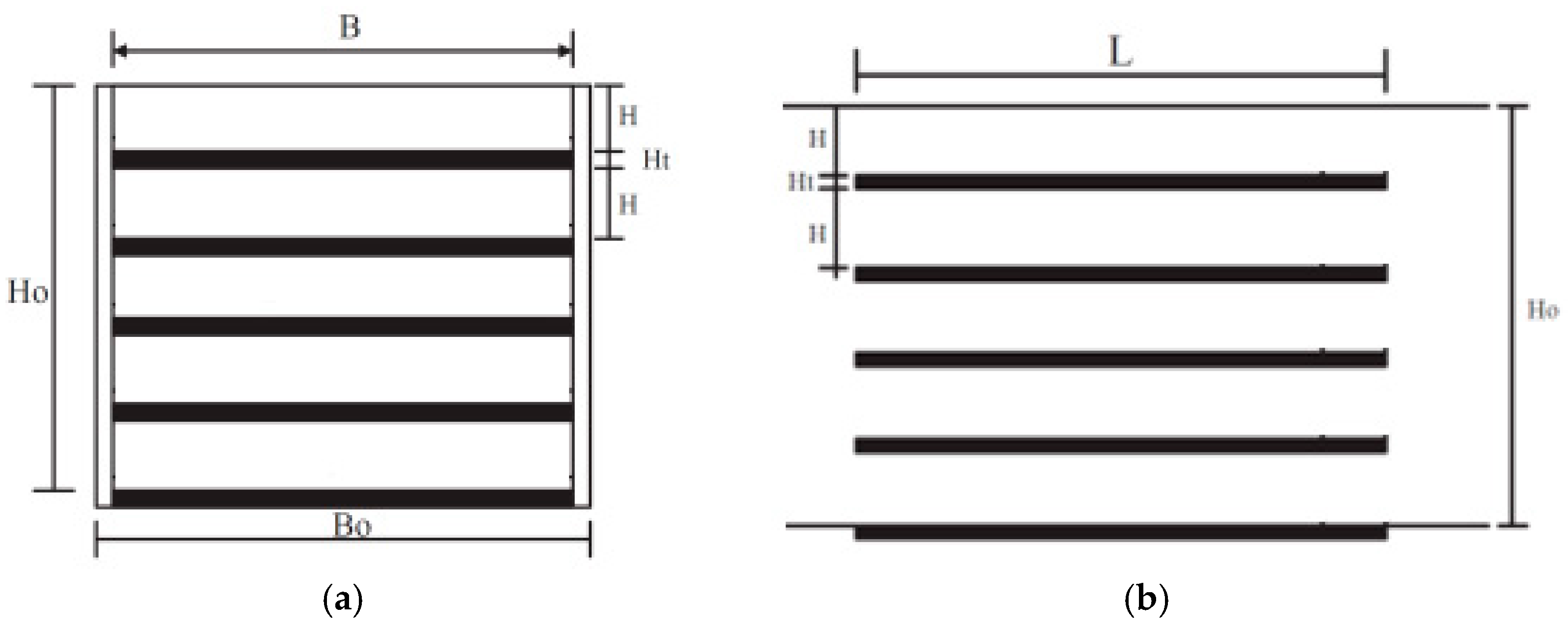
In this study, a salt particle collection device (SPCD, ➐) was installed at the inlet (➎), as shown in
Figure 3. The effect of this device on the heat dissipation performance of the dry storage cask was observed. The height of the SPCD is 0.3 m (Ho), and the width is 0.3 m (B). The length of the collection plate and the length L of the SPCD are 0.5 and 1.0 m, respectively. The plate number is 15.
Taipower’s No. 2 nuclear power plant stores the spent nuclear fuel from the complete GE8x8-2 and ANF8x8-2 rods. The maximum initial average enrichment concentration of U-235 is 3.25% by weight. The maximum average fuel consumption is 35,000 MWD/MTU. The minimum cooling time is 20 years. The maximum decay heat of each fuel bundle is conservatively estimated to be 0.168 kW. Each steel canister can load 87 bundles of nuclear fuel. Therefore, the maximum designed thermal load of each steel canister is 14.6 kW (1.15 kW/m3).
For the specified parameters of the BWR fuel stored in the MAGNASTOR system, the maximum initial average enrichment concentration is 3.8% by weight. The maximum average fuel consumption is 60,000 MWD/MTU. The minimum cooling time is 4 years. The maximum decay heat of each bundle is 0.379 kW. The maximum designed thermal load of the sealed steel cylinder is 33.0 kW (2.6 kW/m
3) when 87 groups of fuel bundles are stored. Therefore, in this study, a thermal load of 1.15 to 2.6 kW/m
3 for each steel canister is employed in the CFD simulation. The geometric data used in the investigated model are shown in
Table 1 and
Figure 2b.
2.3. CFD Simulation
The physical problem under consideration was numerically simulated using a finite volume method to solve the governing equations with the aforementioned boundary conditions (as listed in
Table 2). The calculation domain is shown in
Figure 2b. A commercial CFD code, PHOENICS, was used to simulate the airflow and temperature distributions. The governing equations solved by PHOENIC include the two-dimensional incompressible Navier-Stokes equation, and the convection diffusion equation with the k-ε turbulence model. These equations can be found in the PHOENICS user manual (Spalding [
7]) or any CFD textbook and, thus, will not be provided here. A general wall function was employed to bridge the steep variable-dependent gradients near the solid surface. The iterative calculation was continued until a prescribed relative convergence of 10
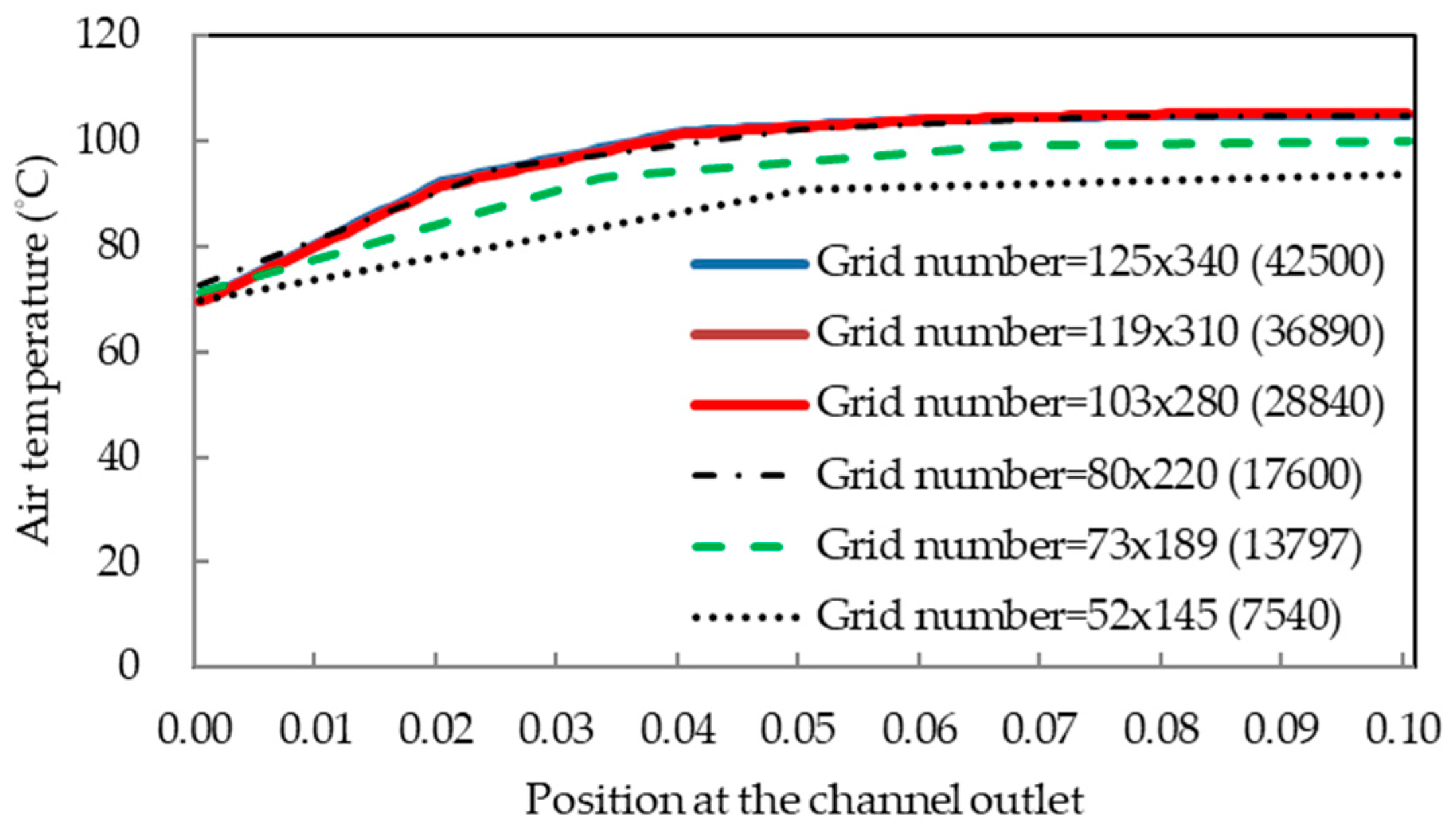
−3 was satisfied for all the field variables in this problem. When tested the grid independence of the mesh domain, the temperature distribution at the channel outlet based on different grid points was used to calculate the deviation percentages and determine a suitable grid point system for our calculations, as shown in
Figure 4. The accuracy of the numerical simulation depended on the resolution of the computational mesh, and a finer grid produced more accurate solutions. Increasing the cell number increased the solution accuracy at the expense of significantly increasing the computational resources required. A grid with approximately 103 × 280 cells was used for the numerical simulation in this study.
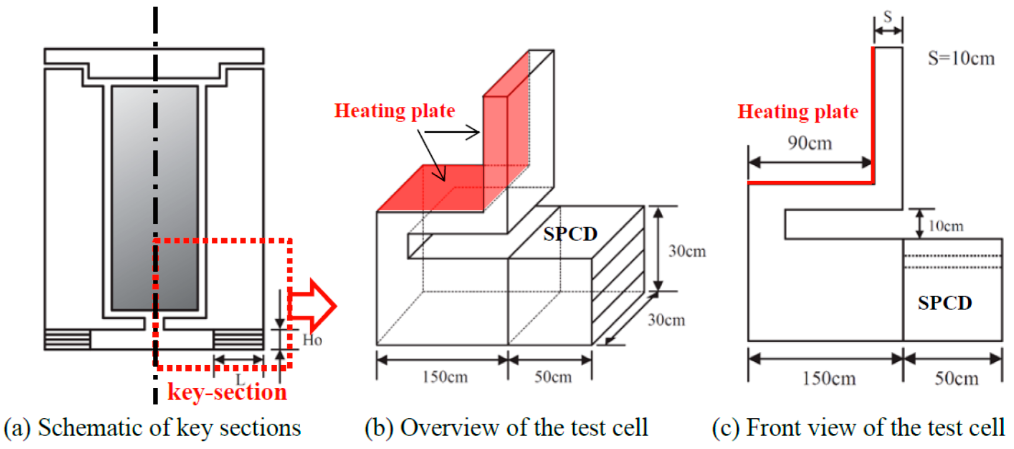
2.4. Key-Section Full-Scale Experiment
In this study, a full-scale test cell for key sections (as shown in the red dotted area of
Figure 5a) of the dry storage cask was built, and the heat flow patterns of the test cell were experimentally observed (as shown in
Figure 5b,c). The experimental results were compared with those obtained from the CFD simulation. The heating power of the spent nuclear fuel in the nuclear waste canister was set to 400 W/m
2. The length of the plate in the SPCD was 0.5 m.
2.4.1. Hot Wall with Heating Flux,
The hot wall (shown in
Figure 5b) was formed by attaching a mica-type heater to a copper plate to simulate the heat generation of spent nuclear fuel. The output power of the heating plate was 400 W/m
2. The thickness of the copper plate was 0.3 cm. The function of the plate is to ensure that the heating wall is uniformly heated. To control the output power, a power supply was connected to a power meter (TES WM-01, TES Corp., Taipei, Taiwan) and the heating plate.
2.4.2. Temperature, Heat Flow and Channel Airflow Velocity Measurements
In this study, type K thermocouples were used to measure the temperatures at multiple locations. The temperatures measured were the surface temperature of the heating plate, the air temperatures at the inlets and outlets of the channels (10 measuring locations each at the inlet and outlet), and the channel wall temperature of the concrete cask. A heat flow meter was placed between the heating plate and the copper plate to measure the heating power. Micro-anemometers were placed at both the entrance (10 locations) and the exit (5 locations) of the flow channel.
2.4.3. Measurement Apparatus
The device and data acquisition system included Data Acquisition Units (YOKOGAWA MX-100, Tokyo, Japan), a personal computer, heat flux sensors (EKO Instruments MF-180, Tokyo, Japan), anemometers (KANOMAX Model 1560, Suita, Japan) and AC/DC power supply units (Gwinstek APS-1102, New Taipei, Taiwan).
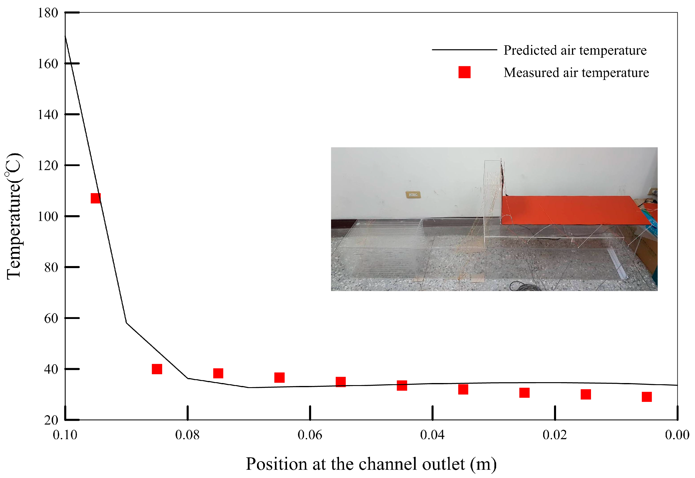
Figure 6 shows that there was no significant difference between the CFD results and experimental results. Thus, the reliability of the simulation results was confirmed.
3. Results and Discussion
In this study, the controlling factors included whether the SPCD was used, the length of the SPCD plate (50 or 100 cm), the heating power of the sealed steel canister (1.15 and 2.6 kW/m
3), and the ambient temperature (25, 30 and 35 °C). Based on the design specifications of Taipower [
6], the evaluation criteria were defined as follows: The maximum acceptable temperature for the spent fuel steel canister was 570 °C (abnormal and accidental conditions). The acceptable temperature for the concrete was either 93.3 °C (the average temperature under normal conditions), 148.8 °C (the maximum local temperature under normal conditions), or 176.6 °C (the maximum local temperature under abnormal or accidental conditions).
3.1. Flow and Thermal Characteristics of the Design Configuration
3.1.1. Flow Pattern Observations
In this section, the flow and thermal characteristics of the dry storage cask are discussed under the following conditions: a 50-cm SPCD is used, the heat dissipation rate of the sealed steel canister is 2.6 kW/m
3 (the worse condition), and the ambient temperature is 30 °C.
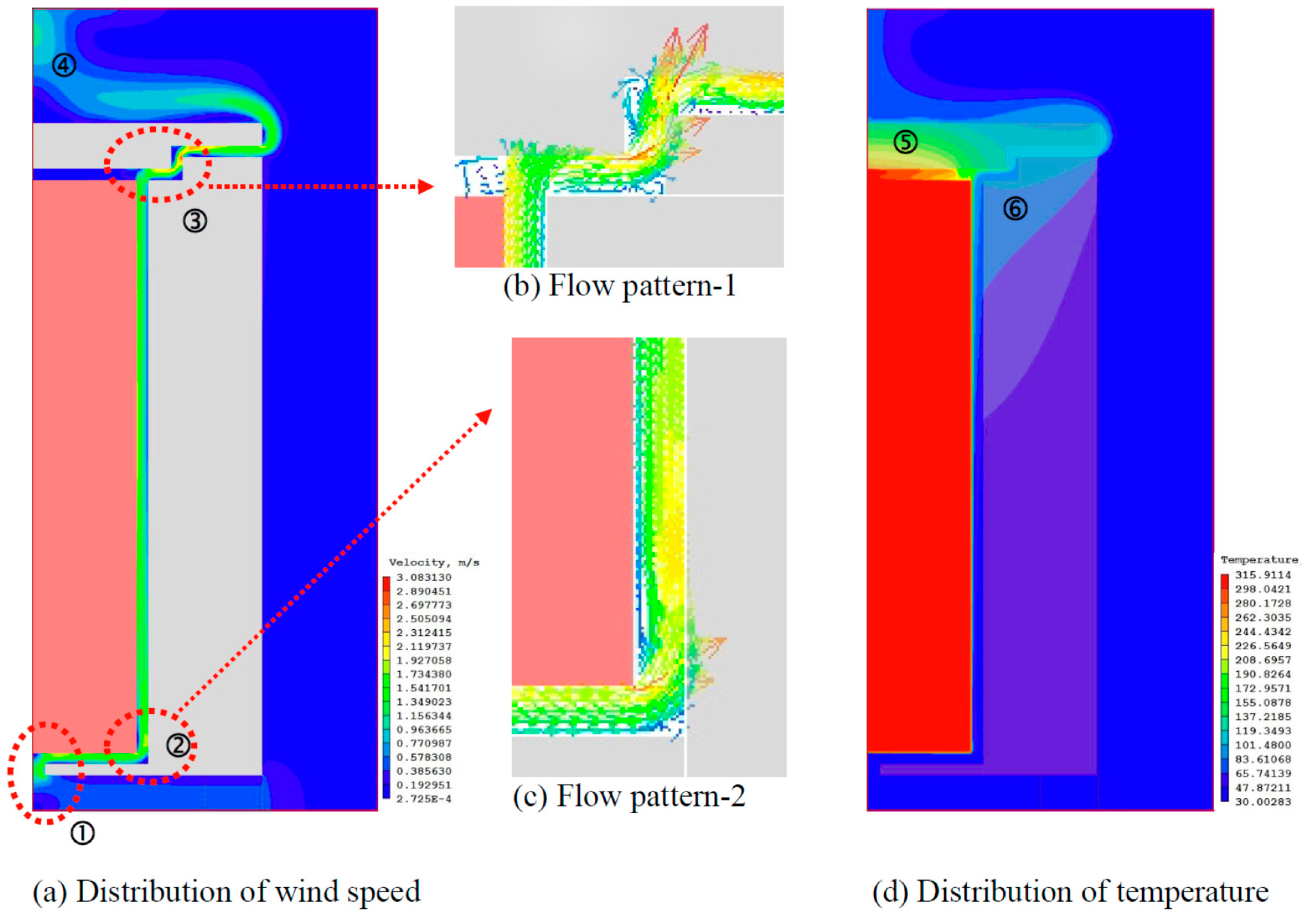
Figure 7a shows the flow velocity distribution.
Figure 7b,c show the flow pattern. These figures illustrate that after the external cold air flows into the dry storage cask from the bottom, the flow separates at the flow turning locations ➀–➂. Additionally, multiple inner circulations exist in the channel. These processes affect the heat transferred by the channel airflow from the nuclear waste canister, which in turn affects the temperature distribution in the dry storage cask and leads to a thermal stress problem. Moreover, due to the Coanda effect, the high-temperature airflow in the dry storage cask merges with the high-temperature airflow from the symmetrical end at the upper-middle section of the dry storage cask (shown by the symbol ➃). The high-temperature airflow enclosing the top concrete lid makes heat dissipation at the lid difficult (denoted by the symbol ➄ in
Figure 7d) and even affects the temperature of the concrete cask (indicated by the symbol ➅ in
Figure 7d).
3.1.2. Thermal Performance
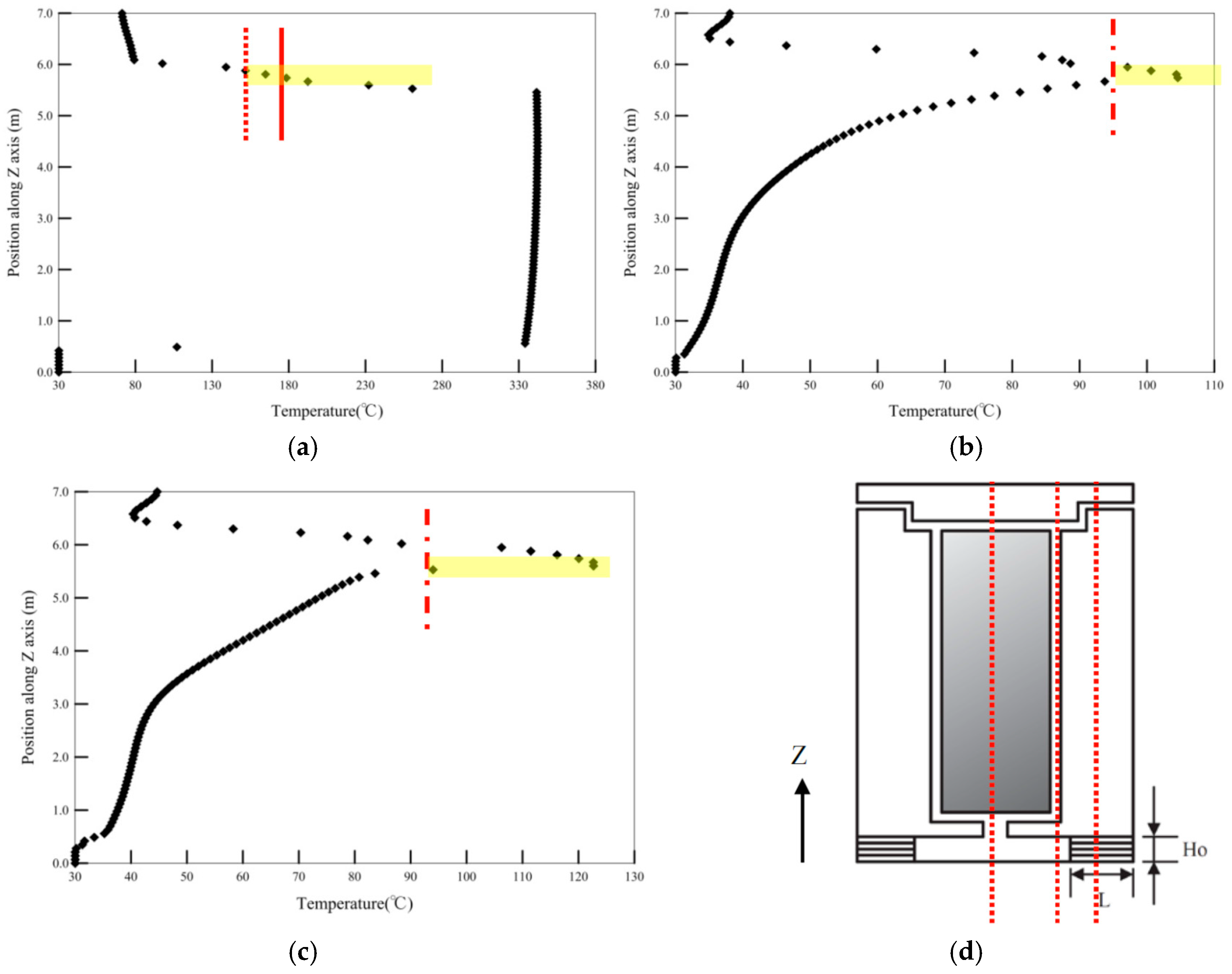
Figure 8 shows the temperature distribution of the dry storage cask at the Y = 3, 2, and 1.5 m sections. This figure shows that the temperature of the steel canister was approximately 334–342 °C, which is less than the evaluation criterion of 570 °C (the maximum acceptable temperature under abnormal or accidental conditions). The temperature of the top concrete lid was as high as 232 °C (at height Z = 5.6 m), which is greater than the maximum acceptable temperature (176.6 °C, indicated by the red solid line) of concrete under abnormal or accidental conditions. Moreover, the temperatures at the lower and upper halves of the top concrete lid were both greater than the respective maximum acceptable temperatures (176.6 °C for the lower half and 148.8 °C for the upper half, as indicated by the red dotted line).
Figure 8b shows that the maximum temperature of the concrete cask was 85.2 °C (at height Z = 5.53 m), which satisfies the design requirements. The temperature of the top concrete lid was greater than the acceptable average temperature of the concrete (93.3 °C, indicated by the red dashed line).
Figure 8c shows that the maximum temperature of the concrete cask was 123 °C (at height Z = 5.6 m), which is greater than the acceptable average temperature of 93.3 °C under normal conditions. The temperature of the lid was also greater than 93.3 °C.
Therefore, overall, the daily operating temperatures of the top concrete lid and at high locations on the concrete cask (indicated by the symbols ➄ & ➅ in
Figure 7d) were greater than permitted by the design specifications. Power plant operators should pay attention to the possible structural damage caused by overheating at these locations. Possible solutions to the thermal stress problem discussed above include the following:
- (1)
Improve the design of the flow channels. The current ventilation flow is associated with the structural spacing. No formal ventilation is designed. If the existing construction cannot be altered, the authors suggest that guide vanes be installed to smooth the airflow and increase the heat dissipation efficiency of the channel airflow.
- (2)
Increase the strength of the RC to enhance its resistance to the generated thermal stress.
- (3)
Use a thermal dissipation design for the top concrete lid and high locations on the concrete cask. The design may include the utilization of additives to improve the heat transfer coefficient of the RC and the installation of heat pipes, among other measures. Such improvements can ensure that the heat gained inside the RC is smoothly transferred to the outside.
In addition to the heat dissipation problem associated with a single dry storage cask, if several dry storage casks are placed together or external air affects the overall heat dissipation (such as the conflict created by thermal buoyancy-induced airflow and wind, as mentioned in paragraph 1 of
Section 2.2), the risk of structural damage caused by poor heat dissipation will be even greater.
3.2. The Impact of the SPCD
Compared to devices without SPCDs, utilizing a 50-cm SPCD can increase the heat transferred by the channel airflow by approximately 7.6% (data not shown, due to the page limitation). Utilizing a 100-cm SPCD increases the heat transferred via the channel airflow by approximately 7.1% (in both cases, the heating power of the sealed steel canister ranges from 1.15 to 2.6 kW/m
3). Since the SPCD has a plate-like configuration, when the 50-cm SPCD unit is installed in the dry storage cask, its rectification-like effect (
Figure 2 ➐ and
Figure 3) increases the average rate of channel airflow (compared with cases without SPCDs). However, when the plate length is increased from 50 to 100 cm, the average flow rate slightly decreases due to the increase in the flow friction. Compared to devices without SPCDs, the average flow rate of the dry storage cask with a 100-cm SPCD is greater, and thus, more heat is transferred by the channel airflow.
4. Conclusions
In this study, based on CFD simulations and heat flow experiments, the thermal performance of a dry storage cask was investigated. Additionally, the effect of an SPCD on the heat dissipation characteristics of a dry storage cask was evaluated. The object studied was a dry storage cask with a steel canister (with a diameter of 1.8 m and a height of 5 m) containing spent nuclear fuel and a surrounding 1-m-thick concrete cask. The flow channel between the nuclear waste steel canister and concrete casks had a spacing of approximately 10 cm. The results indicated that there are multiple inner circulations in the airflow channel. These processes affect the heat transferred by the channel airflow from the nuclear waste canister, which in turn affects the temperature distribution of the dry storage cask and results in thermal stress. Overall, the daily operating temperatures at the top concrete cover lid and the upper locations of the concrete cask were greater than those permitted by the design specification. Power plant operators should pay attention to the possible structural damage caused by overheating at these locations. The SPCD does not adversely affect the heat dissipation performance of the dry storage cask.
Acknowledgments
Support from the Atomic Energy Council, Taiwan and the Ministry of Science and Technology, Taiwan through grant No. MOST 106-NU-E-390-001-NU in this study is gratefully acknowledged.
Author Contributions
H.-Y.C. and C.-M.L. conceived of and designed the investigated model; H.-Y.C. and C.-M.L. performed the experiments; R.-H.C. and H.-Y.C. performed the numerical simulation; H.-Y.C., R.-H.C. and C.-M.L. analyzed the data; and H.-Y.C. and C.-M.L. wrote the paper.
Conflicts of Interest
The authors declare no conflict of interest.
References
- Xie, H.; Gao, Z.; Zhou, Z. A numerical investigation of natural convection heat transfer in horizontal spent-fuel storage cask. Nucl. Eng. Des. 2002, 213, 59–65. [Google Scholar]
- Pugliese, G.; Lo Frano, R.; Forasassi, G. Spent fuel transport cask thermal evaluation under normal and accident conditions. Nucl. Eng. Des. 2010, 240, 1699–1706. [Google Scholar] [CrossRef]
- Koga, T.; Tominaga, Y. Heat removal characteristics of a concrete cask by a simplified test model. Nucl. Eng. Des. 2008, 238, 1189–1195. [Google Scholar] [CrossRef]
- Li, J.; Liu, Y.Y. Thermal modeling of a vertical dry storage cask for used nuclear fuel. Nucl. Eng. Des. 2016, 301, 74–88. [Google Scholar] [CrossRef]
- Kim, H.M.; No, H.C.; Bang, K.S.; Seo, K.S.; Lee, S.H. Development of scaling laws of heat removal and CFD assessment inconcrete cask air path. Nucl. Eng. Des. 2014, 278, 7–16. [Google Scholar] [CrossRef]
- Taiwan Power Company. Analysis Report on the Safety of a Dry Storage System in the No. 2 Nuclear Power Plant; Taiwan Power Company: Taipei, Taiwan, 2011. (In Chinese) [Google Scholar]
- Spalding, D.B. The PHOENICS Encyclopedia; CHAM Ltd.: London, UK, 2012. [Google Scholar]
© 2018 by the authors. Licensee MDPI, Basel, Switzerland. This article is an open access article distributed under the terms and conditions of the Creative Commons Attribution (CC BY) license (http://creativecommons.org/licenses/by/4.0/).


