A New Control Logic for a Wind-Area on the Balancing Authority Area Control Error Limit Standard for Load Frequency Control


Faculty of Electronic Information and Electrical Engineering, Dalian University of Technology, Dalian 116000, China
*
Author to whom correspondence should be addressed.
Energies 2018, 11(1), 121; https://doi.org/10.3390/en11010121
Submission received: 16 November 2017
/
Revised: 5 December 2017
/
Accepted: 31 December 2017
/
Published: 3 January 2018
(This article belongs to the Section F: Electrical Engineering)
Abstract
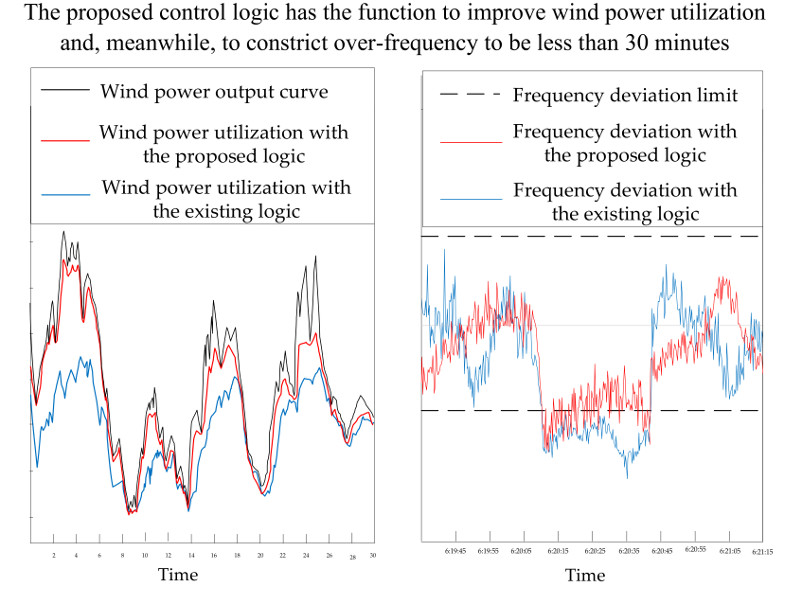
:Nowadays, the Balancing Authority Area Control Error (ACE) Limit (BAAL) Standard has been adopted to replace the Control Performance Standard 2 (CPS2) in the North American power grid. According to the new standard’s mechanism, a new control logic, named “Triggered Monitoring and Graded Regulation” (TM-GR) is proposed. Its purpose is to improve wind power utilization, with good BAAL Standard compliance for load frequency control (LFC). With the TM logic, according to the real-time regulating ability of areas and forecasting results of wind power output, the triggering moments to give orders are found and a defined monitoring interval is set to track the succeeding fluctuation of Area Control Error (ACE). With the GR logic, based on whether or not over-limit frequency and over-limit ACE occur simultaneously, unit output is regulated in different grades. In cooperation with the existing control logic of Control Performance Standard 1 (CPS1), the proposed logic has a higher priority. From the test results, with the proposed control logic, the utilization of wind power output increases and, meanwhile, the area’s control performance meets the Standard BAL-001-2 requirements. The standard deviation of the frequency deviation is less than the target value, and the duration of over-limit ACE and over-limit frequency can both be restricted to be less than 30 min.
1. Introduction
The control areas in an interconnected grid not only share the benefits of interconnection but share the responsibilities to maintain frequency stability by load frequency control (LFC). Control performance standards need to be set to monitor and assess areas’ control actions [1,2,3]. As for the areas, they would design an appropriate control logic based on their regulation characteristics and capability. The logic is used to reduce the operating cost under the precondition of meeting the standard requirements [4,5,6].
In respect of assessment on LFC performance, every power grid has its own standard, which was designed based on its operating environment [7,8,9]. In the American power grid, the North American Electric Reliability Company (NERC) has been doing much work on standards for decades, and keeps proposing new standards which apply to the new requirements and changes of environments [10]. Up to now, three standards have been designed by the NERC: the Control Performance Criteria (CPC) [11], the Control Performance Standard (CPS) [12], and the Standard BAL-001-2 [13]. CPC was officially implemented in the eastern grid of North America in 1973. However, because it lacked a defensible theoretical basis, it was replaced by the CPS containing the CPS1 and the CPS2 in 1988. Through years of operating practices and theoretical analysis, some of the sub-standard CPS2’s disadvantages had been found. In 2002, to replace the CPS2, the NERC put forward several requirements based on a new idea of the Balancing Authority Area Control Error (ACE) Limit (BAAL) [14]. The standard in which the limit of BAAL is used is named the BAAL Standard. The standard requirements can be described that the duration of over-limit Area Control Error (ACE) cannot be longer than 30 clock-minutes [13,15]. In 2005, Priority-based Control Engineering (PCE), whose work is to explore the science and technology of generation control, tested the new standard in some grids [16], such as the Eastern Interconnection (EI) and the Western Electricity Coordinating Council (WECC). During the test, PCE gathered much helpful feedback from operation and management entities. In 2013, the BAAL Standard was passed by the ballot pool of the NERC. In the “Reliability Standards for the Bulk Electric Systems of North America” of 2017 [17], the BAAL Standard and the CPS1 formed the officially adopted Standard BAL-001-2. Though the operation practices show that the BAAL Standard is very effective in enhancing reliability and improving frequency quality, there is little research on control logic on this new standard at present. Since the BAAL Standard aims to restrict the number of continuous clock-minutes of over-limit ACE, the past control logic [18,19], which was used formerly for the CPS and the CPC, cannot be followed. In [9], a real-time control logic of a hydroelectric-dominated utility based on new standard is put forward which minimizes the generation maneuvering. In [15], a methodology for incorporating the timing component into the regulation requirements calculation is proposed based on the BAAL Standard. The existing control logics for the new standard mainly concentrated on how to decrease the action times of generating units. They were not designed to deal with the integration of renewable energies into a power grid.
With the rapid development of renewable energy generation [20,21,22,23], the proportion of installed capacity of wind power in power grids has been increasing in recent years [24,25,26,27]. The global wind power industry installed 54.6 GW in 2016. At the end of 2016, the number of countries with more than 1000 MW installed capacity was 29 and the global total capacity was 486.8 GW [28]. Wind generation in the ENTSO-E network will increase in the next 10 years from 139 GW to between 197 and 255 GW [29]. However, the main problem faced at present is massive wind power curtailment [30,31]. Many factors influence wind energy curtailment, such as inaccurate wind forecasts, network congestion, and reliability requirements [32,33,34]. The Spanish Transmission System Operator (TSO) has curtailed wind power to give priority to scheduled energy and to improve grid stability [35]. The wind curtailment in China is mainly due to the lack of adjustment of planning, grid management, and related policies against the volatility of wind power [36,37]. The level of wind curtailment is determined under varying levels of offshore wind, system non-synchronous penetration (SNSP), and transmission constraints in Ireland [38,39]. Because of the random variation of wind power output, it is hard to make a daily generation schedule by forecasting the output fluctuation exactly [40,41]. To better represent the wind power uncertainty, various representations of wind power forecast uncertainty have been proposed, such as probability distributions [42,43], scenarios [44], intervals [45], and uncertainty sets [41]. Because of the randomness of wind speed, it is impossible to regulate wind turbines like conventional units [46,47]. So, wind turbines were arranged with no responsibilities on LFC in former times. However, as the installed capacity gets larger, some systems and methods are used to improve the precision of forecasting wind power output [48,49]. In [48], a novel hybrid methodology for forecasting is proposed, successfully combining three individual forecasting models using the adaptive neuro-fuzzy inference system (ANFIS). In [49], a forecasting model consisting of the Gaussian process with a novel composite covariance function for high-accuracy wind power forecasting is presented. With the effective forecasting technologies, some ideas and methods have been proposed to try to involve wind turbines in frequency regulation [50,51]. In addition, there is also some research on how to minimize the wind curtailment [52,53].
Although some useful control logics and strategies of a wind-area have been designed for LFC, most of the existing research is based on CPS, which has been replaced by the Standard BAL-001-2. As mentioned above, the BAAL Standard in BAL-001-2 sets new requirements for ACE and frequency control. Under the new conditions, there is a need to study how to make high efficient use of wind generation to maintain frequency stability. This paper proposes a new control called “Triggered Monitoring and Graded Regulation” (TM-GR), which takes control areas’ regulation capacity and the forecasting results of wind power output into consideration. In the TM logic, some triggering moments are defined to give orders and a monitoring interval is set to track ACE fluctuation. In the GR logic, based on whether or not the over-limit frequency and over-limit ACE occur during the same period, unit output is regulated to different degrees. Test results show that the proposed logic has the ability to reduce wind power curtailment and, meanwhile, to make frequency performance meet the standard requirement by managing ACEs.
Since the BAAL Standard requirement should be complied with in both normal and abnormal practical operation [17], the proposed control logic is always effective to improve wind power utilization whether or not some great disturbances or critical events on operation occur. The design concept of the BAAL Standard has much in common with the standards in other girds, such as the China and European grids. In the European grid, the Network Code sets some frequency quality requirements which propose acceptable ranges and limited time durations, just like the NERC has done [54,55]. Additionally, in the China grid, the feasibility of implementing the BAAL Standard has been discussed for years to design a new set of reliability standards [56,57]. Therefore, with the high penetration of renewable energies in almost all of these grids, the proposed logic may have extensive applicability and practical significance.
The rest of this paper is structured as follows. A deep analysis on the BAAL Standard is done in Section 2. With the analysis, the standard’s connotation and purpose are presented. The new control logic is proposed and how it can cooperate with the existing CPS1 logic is shown in Section 3. Section 4 presents simulation results, which include wind power utilization, performance of over-limit frequency and ACE, and regulation on ACE of the new logic. Section 5 shows the conclusion.
2. Analysis on the BAAL Standard
2.1. Description of the Standard
In CPS, the sub-standard CPS1 aims to maintain the frequency quality by restricting the standard deviation of frequency fluctuation over a year, and the sub-standard CPS2 aims to limit the occurrences of over-limit ACE in a month by using probabilistic methods [10,12]. Therefore, the two sub-standards focus on long-term frequency or ACE performance. Since a frequency performing too high or too low during a short duration would be harmful for the normal work of electric equipment and its stable operation, the BAAL Standard drafting team was concerned with short-term control performance. Maintaining short-term frequency quality and operational security is regarded as the basis for setting new requirements for areas’ control actions. The requirement can be described that clock-minute average of the reported ACE cannot exceed the clock-minute BAAL for more than 30 consecutive clock-minutes. It can be expressed as [13,16,17]:
When frequency deviation is positive,
When frequency deviation is negative,
where is the consecutive clock-minutes; is the clock-minute average of the reported ACE; is the limit for duration time, which is decided as 30 min; and is the BAAL, which can be expressed as:
where is the trigger frequency deviation limit, which is decided to be ; is a target value that has been obtained from the historical frequency data; is the actual frequency deviation; and is the frequency bias coefficient of a certain area.
In assessing an area’s control performance, a duration of over-limit ACE which is over 30 clock-minutes means the violation of the standard’s requirement. The area would be punished economically. The BAAL Standard sets four violation severity levels according to the duration of over-limit ACE [17], which are described in Table 1.
2.2. Interpretation of the Standard
2.2.1. Purpose of the Standard
From Equations (1) and (2), the formulation of the requirement in different cases of negative and positive frequency deviation is not same. However, the different requirements have a uniform purpose. The purpose would be derived as below, by taking the example of negative frequency deviation.
Combining Equations (2) and (3), the below equation can be obtained.
where is the clock-minute average of the ACE of area i.
If a grid is assumed to include m control areas, then
So, if every area meets the requirement shown as Equation (4), Equation (6) would be obtained according to Equation (5).
Namely,
In the case of positive frequency deviation, Equation (7) can still be obtained. Therefore, the purpose of the BAAL Standard is to restrict consecutive time of over-limit frequency, as Equation (7) shows.
2.2.2. Characteristics of the Standard
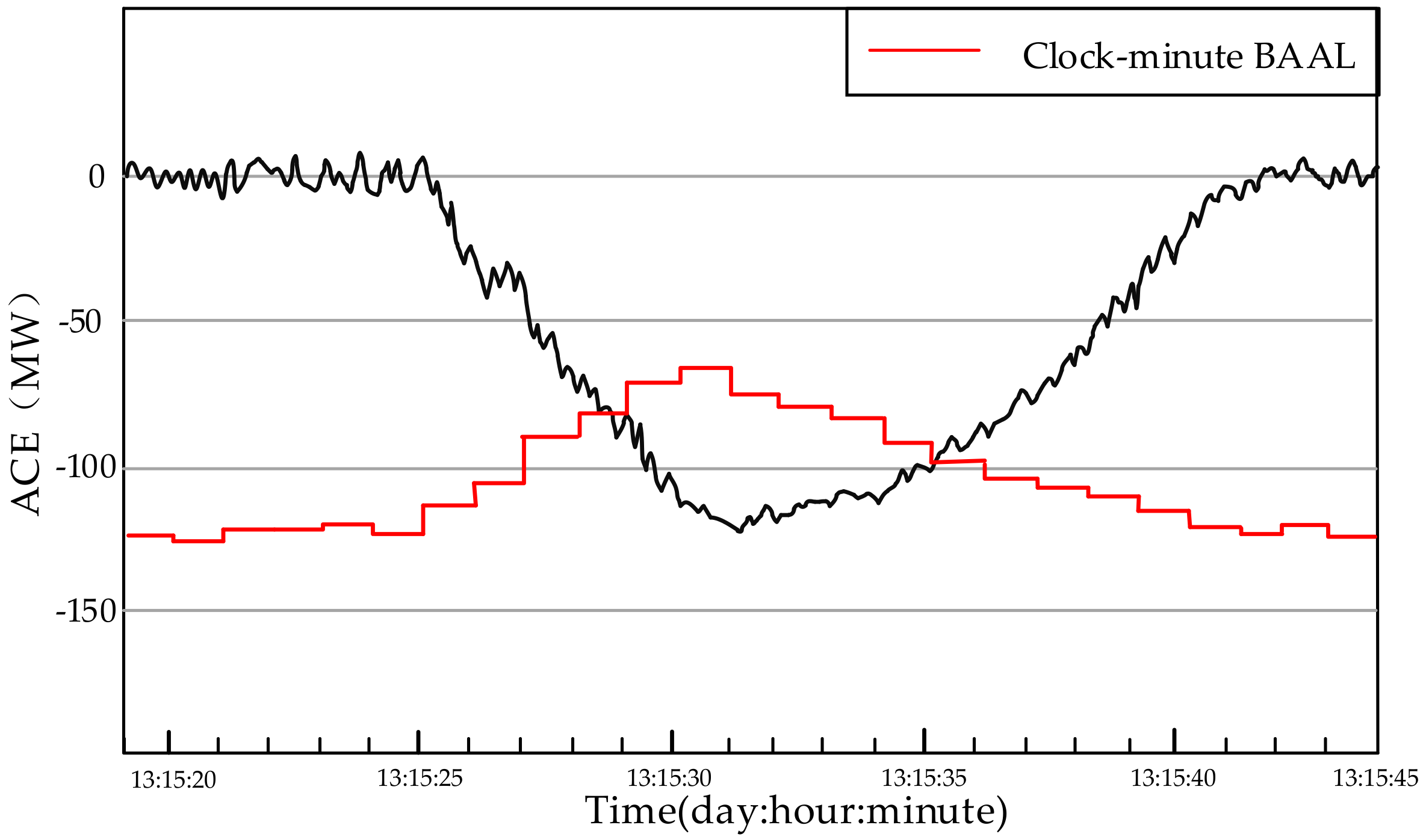
The standard’s requirements for ACE and frequency can be described in Figure 1. From the figure and the equations above, some characteristics can be found.
- Dynamic BAAL related to frequency. BAAL changes with actual frequency deviation. A larger absolute value of frequency deviation brings a smaller BAAL for the ACE. When the ACE has a different sign with frequency deviation, it is beneficial for maintaining frequency quality. In this case, the size of the ACE would not be restricted. This philosophy fits the requirement of secure and economic operation.
- Different requirements for different areas. Different requirements for ACEs mean different regulation responsibilities of areas. determines different areas’ BAALs at the same frequency deviation. From (3), an area with a smaller would be assigned a stricter requirement, because frequency is more sensitive to its ACE.
- Permitting correlations between ACEs. If each area’s clock-minute average of reported ACE is within its BAAL, no matter whether or not there are correlations between ACEs, the clock-minute average of frequency deviation can be maintained within the range from to . When the duration of each over-limit ACE is less than 30 min, the duration of over-limit frequency would not be more than 30 min. By contrast, in the CPS2 design, it is assumed that there is no correlation between different ACEs [12]. However, correlations indeed exist in an actual grid. So, the BAAL Standard is more practical than the CPS2 on this point.
3. Proposed Control Logic
3.1. Design Philosophy
As the utilization of renewable energies in the electrical power industry develops, taking use of wind power as much as possible on the premise of secure operation is a vital mission under the new environment of the grid. Therefore, for a wind-area, only regulating conventional units without restricting wind power under non-emergency situations can make the most of complementarity between wind power output and load demand. This action can improve the utilization of wind power and effectively deal with the effects of random load fluctuation on real power balance.
On the other hand, a frequency performing too low or too high for some time in duration can harm the equipment and components in the system [58,59]. For that reason, generator units traditionally have a protection function for abnormal frequency [60,61]. Abnormal frequency protection will be activated when the frequency continuously exceeds the specified safe limit for a short duration. For the sake of short-term security, the duration of over-limit frequency is restricted to be not over 30 min in the BAAL Standard requirements. When positive frequency deviation is continuously large for some time, it might threaten secure operation. If the duration time is close to 30 min, derating part of the wind power output should be considered to cooperate with the conventional units’ efforts to restore frequency quality in a timely manner.
The maximum duration time of over-limit ACE allowed in the BAAL Standard is 30 clock-minutes, which is a relatively long time. However, since the conventional units have a limited ability to adjust output and wind power output has strong uncertainty, the wind-area should monitor the real-time ACE fluctuation and available regulating ability continuously. Then, it should judge when to give a regulating order based on the forecasting results of wind power output. This action can avoid failing to bring the ACE to be below the BAAL within 30 min due to an insufficient regulation ability or a large power shortage, and can decrease the wind power curtailment. By this way, short-term operation security would be enhanced and wind power utilization would be increased.
Based on the above discussion, a control logic named “Triggered monitoring and Graded Regulation” (TM-GR) is proposed. With the TM logic, whether to give regulating orders is decided at the end of every clock-minute during every 30-min interval. The basis of a decision is the ACE size at that moment and the ACE performance before that moment. The moment when an order is given is called the “triggering moment”. After giving an order, a certain monitoring interval is arranged. During the interval, the ACE fluctuation would be monitored continuously and the next triggering moment may be found. With the GR logic, based on whether or not the over-limit frequency and the over-limit ACE occur during the same period, unit output is regulated in different grades. When only the ACE exceeds its BAAL continuously, the regulation is in grade one. When the ACE and the frequency exceed their limits simultaneously, the regulation is in grade two.
3.2. Triggered Monitoring
In the TM logic, the main work is to decide the triggering moment and the monitoring interval. A wind-area’s control performance on real power balance is affected by whether or not the triggering moment is decided reasonably. If the order is given too soon, regulation times and cost would increase and wind power curtailment would even happen. If the order is given too late, the restoration process of frequency quality may be influenced. Therefore, the triggering moment should be decided according to the area’s real-time regulating ability, together with the forecasting results of wind power output. It is the right time to give an order when the over-limit ACE performance is about to exceed the area’s ability to control it.
From Equation (3), the BAAL has the same sign as the actual frequency deviation. When the frequency deviation is negative, unit output should be increased to regulate over-limit ACE and vice versa. The time to restore the ACE is restricted according to the standard requirement. Therefore, when units need to decrease output, the area’s regulating ability mainly refers to the regulation rate. On the other hand, when the output should be increased, the regulation rate and the available generation capacity reflect the regulating ability. Therefore, the triggering moment in the TM logic should be decided according to both of them, in addition to the wind power forecast results. The reported ACE and BAAL would be calculated every clock-minute, as the BAAL Standard requirement says [17], so the end of every clock-minute during every 30-min interval is the moment to judge whether to give orders.
If the ACE has been exceeding its BAAL for clock-minutes, there would be left clock-minutes for the area to bring the ACE to be within the BAAL. Conventional units’ total regulation rate to increase and decrease output are respectively described as and . The maximum power generation to increase and decrease in can be respectively expressed as and :
where is the wind power output change after , which is forecasted at the end of .
If the frequency deviation is positive, Equation (9) can describe the area’s regulating ability . In the case of negative frequency deviation, the regulating ability should consider the available generation capacity in the future as well. They can be expressed as:
where and are both positive; and is the available capacity during the time of .
If the area did not have an adequate regulating ability to deal with the severity of the over-limit ACE at the end of , it needs to give an order to adjust the conventional units’ output. This can avoid the ACE surpassing the controllable scope. In this situation, is regarded as the triggering moment. The situation can be expressed as:
When the frequency deviation is negative,
When the frequency deviation is positive,
where
where is the reported ACE at the end of ; is the margin coefficient, which can be decided to be less than 1; is the raw ACE produced by the load demand and conventional units’ output at the end of ; and is the wind power output.
The regulating order for conventional units can be expressed as:
where is the regulation coefficient, which can be decided to be about 1.
means decreasing the conventional units’ output, but the wind power would not be affected. In a word, the below equation can be regarded as the judgment to decide the triggering moment .
When the frequency deviation is negative,
When the frequency deviation is positive,
After giving an order at the moment of , a monitoring interval of , during which the ACE fluctuation would be tracked continuously, is set. The follow-up actions to be taken under different conditions are described in Table 2.
When the frequency deviation is negative,
When the frequency deviation is positive,
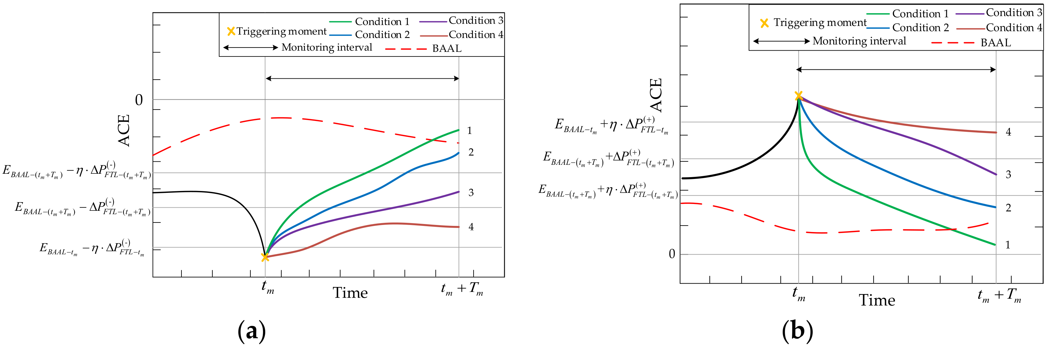
Condition 1 in Table 2 can be described as line 1 in Figure 2a,b. That means the order given at the moment of has played a much more active role in restoring the ACE and avoiding it exceeding the limit continuously. In this case, it should clear the primary orders to reduce the number of times of regulation and to maintain economic operation.
Condition 2 in Table 2 can be described as line 2 in Figure 2a,b. It means the order given at the moment of has played a certain active role in restoring the ACE to the controllable range in time and has succeeded in solving the problem of insufficient regulating ability. In this situation, it should also clear the primary orders. Then, it should continue counting the time of over-limit ACE to find the next triggering moment.
Condition 3 in Table 2 can be described as line 3 in Figure 2a,b. It means that the order given did not work or that other accidents occurred to make the ACE exceed the controllable range. In this case, should be regarded as a new triggering moment. Then, a new order which is expressed as Equation (15) would be given. The ACE fluctuation during the next monitoring interval and the ACE size at the end of would be checked to take the next actions according to Table 2.
Condition 4 in Table 2 can be described as line 4 in Figure 2a,b. That means the order failed to do any work. What is more, the severity of the over-limit ACE at the end of has exceeded the controllable scope. The regulating rate or available generation capacity would be unable to bring the ACE back to the secure range. For the condition of line 4 in Figure 2a, some contingency reserve is needed to go into service. Regulation responsibilities would be assigned among all available regulation resources. In the case of line 4 in Figure 2b, a certain part of the wind turbines would be cut and, at the same time, conventional units would decrease their output as soon as possible. In the process of derating part of the output of the wind power, some constraints on the wind turbines should be taken into consideration, such as rated speed, generator torque, and tip speed ratio [62,63]. Meanwhile, the parameters, including the ramp-rate and the spinning reserve [64,65], which are set by the wind power plant’s operator, should be complied with as well in a practical grid. After giving a new order, as in condition 3, the ACE fluctuation during the next monitoring interval would be tracked continuously.
In a word, ACE fluctuations in Condition 1 or 2 would clear the primary orders. ACE fluctuations in Condition 3 or 4 would give a new order and repeat the control logic described above until Condition 1 or 2 occurs. In these four conditions, only Condition 4 with a positive frequency deviation gives the order to cut part of wind turbines. Thus, the proposed control logic is good for increasing the utilization rate of wind energy.
In addition, in order to ensure that the duration of over-limit ACE would not be over 30 clock-minutes, a certain risk time, which is decided to be 30 clock-minutes, is set. If the duration of the over-limit ACE has been equal to the defined risk time, some emergency control actions would be taken in the next minute, such as cutting interruptible load or starting wind power curtailment to decrease the ACE size.
3.3. Graded Regulation
In an interconnected grid, one ACE or some ACEs exceeding the defined limits may not result in over-limit frequency, since there is a complementary relationship between different areas’ imbalance power. However, to ensure the fairness that every area bears equal responsibility in maintaining the real power balance of the grid, the BAAL Standard requires that each area’s over-limit ACE should not last for too much time. So, at the end of every clock-minute, Equations (16) and (17) should be used to find the triggering moment. The order which is expressed as Equation (15) belongs to the regulation in grade one. When an area’s ACE and frequency continuously exceed their limits during the same period, this area is supposed to be mainly responsible for the bad frequency performance. Its over-limit ACE should be regulated to a larger degree in order to recover frequency to the secure range rapidly. The regulation would be in grade two and the order can be expressed as:
where is the enhanced regulation coefficient, which is decided to be more than 1.
3.4. Cooperation with CPS1 Control Logic
In 2017, Standard BAL-001-2, which is comprised of the BAAL Standard and the CPS1, came into operation. The cooperation between the two sub-standards is very important for the stability and security of grid operation, especially after wind power grid integration in a large scale. This section mainly shows how the proposed “TM-GR” logic of the BAAL Standard works smoothly together with the existing CPS1 control logic.
The aim of CPS1 is to restrict the standard deviation of one-minute frequency deviation over one year, and this is beneficial to maintain long-term frequency quality. To achieve the control objective, the standard defines some requirements for the ACE. They can be expressed as:
where is the average over one year; and is the assessment index over one year. When is larger than 100%, the area performance is considered to meet the requirement.
Though CPS1 concerns the frequency performance over one year, the usual control logic used is the two-layer control scheme. The bottom layer is the main control, called the Real-time Control, and the top layer is the feedback control, called the Long-Term Control [66,67]. In the bottom layer, the time unit for observation is one minute. When in Equation (21) is larger than the predefined threshold, the order to control the ACE would be given. The predefined threshold which determines the control tightness is decided in the top layer according to the progressive measurement of CPS1 performance. If the measurement is rather better, there is room to raise the control threshold for unit control relaxation. Otherwise, the control threshold should be set lower for more control actions. From the above, the area’s one-minute performance is the basis of dynamic control in the two-layer control logic.
According to Equations (1)–(3), the requirement of the BAAL Standard can be expressed as:
By contrasting Equation (21) with (23), CPS1 is found to be homologous to the BAAL Standard. Both of them take use of the measurement of to assess an area’s control performance. CPS1 compares it with , while the BAAL Standard has as a reference. CPS1 concerns the fluctuation of its size over one year, while the BAAL Standard pays attention to the continuous time of exceeding the limit. CPS1 rules the spatial distribution characteristics of frequency deviation, and the BAAL Standard defines its continuous distribution. The BAAL Standard has the function of helping CPS1 maintain frequency quality on a short time scale. Though the two standards have different concerns, their control logics do not contradict each other. Control actions which aim to meet the BAAL Standard requirement would not hinder the improvement of the area’s CPS1 measurement. Similarly, the actions to promote CPS1 compliance would not go against the BAAL Standard requirement.
Figure 3 shows the cooperation between the proposed “TM-GR” logic and the existing CPS1 control logic mentioned in [66]. From the perspective of operation security, short-term security is the precondition for maintaining long-term frequency quality. Thus, the BAAL Standard has higher priority than CPS1 in control logic. Under normal conditions, unless triggering moments are found, the BAAL logic will not give orders and control actions will only be managed by the CPS1 logic. Once the ACE performance meets Equation (16) or Equation (17), the short-term operation security is threatened. In this case, the BAAL logic’s orders are given and a subsequent regulating process will be done according to Table 2. Since these orders aim to reduce the ACE’s size, it has the function to improve CPS1 measurement. So, when the BAAL logic’s orders are in action, the CPS1 logic’s orders are shielded.
4. Simulation Test
4.1. Test Conditions
A two-area power grid modified from the IEEE 30-bus test system is used throughout all the tests [68,69]. There are three wind turbines and three conventional thermal units in area 1. There are five conventional thermal units in area 2. The one-month wind power data and load data come from a wind-area in the Northeast China grid [70]. The test parameters are shown in Table 3. The CPS logic and the Standard BAL-001-2 logic are tested under the same situation. The test results contain wind power utilization, frequency performance, ACE performance, and the occurrences of over-limit frequency and ACE. In the CPS logic, the CPS1&CPS2 two-layer control logic is used [66]. In the Standard BAL-001-2 logic, the proposed TM-GR logic is cooperated with the CPS1 two-layer logic.
4.2. Test Results
4.2.1. Wind Power Utilization
The wind power utilization with the two logics is shown in Figure 4. It can be seen that, with the CPS logic, the wind power utilization amount in area 1 is less at every moment. In contrast, the utilization curve with the BAL-001-2 logic gets closer to the output curve. The main reason is that the CPS2 two-layer control logic does not distinguish between conventional units and wind turbines. To meet the CPS1&CPS2 requirement, area 1 decreases the conventional unit output and performs wind power curtailment at the same time. This will cause some unnecessary generation maneuvering and fail to take advantage of complementarity between the wind power output and the load demand. A monthly wind power curtailment rate can be defined to describe the curtailment amount. The rate is calculated by dividing the integral of the difference between the monthly utilization curve and the output curve by the integral of the monthly output curve. The monthly rates with the two logics are shown in Table 4.
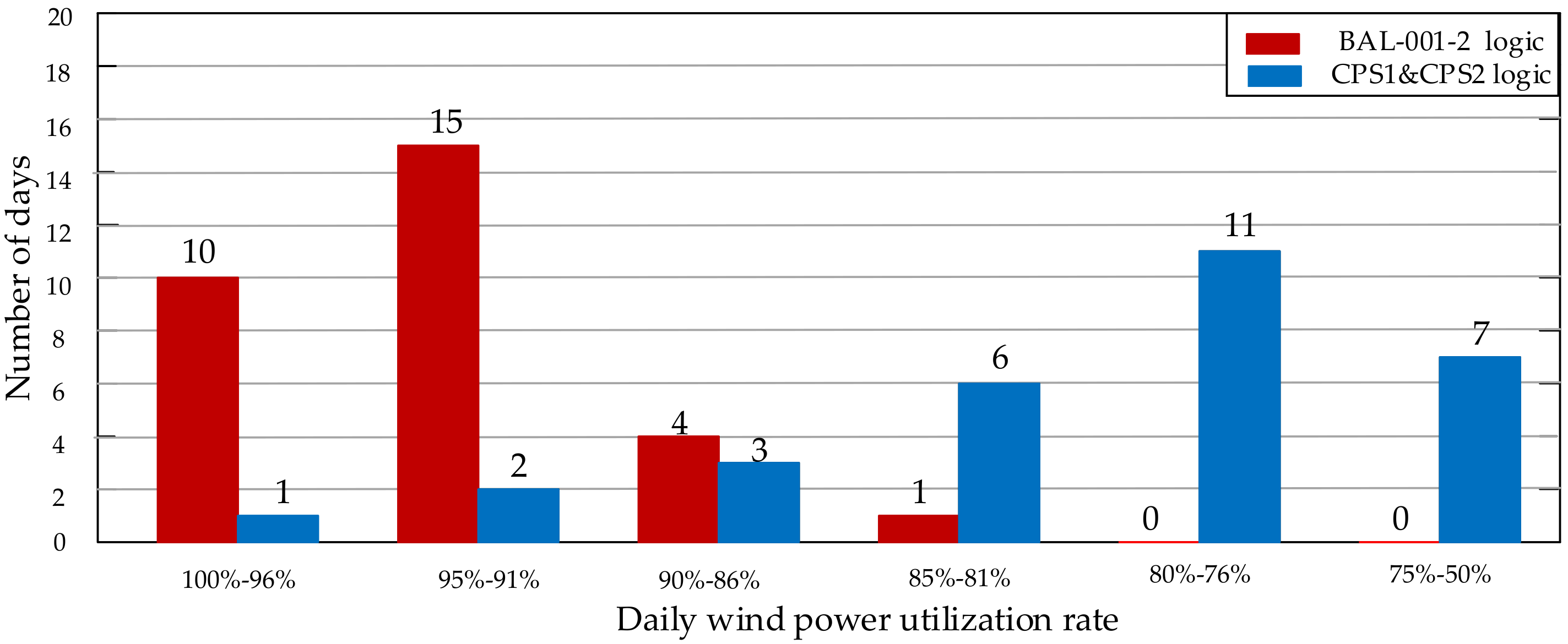
Figure 5 shows the distribution of days in different ranges of daily wind power utilization rate. The daily rate is calculated by dividing the integral of the daily utilization curve by the integral of the daily output curve. With the CPS logic, 24 days are distributed in the range from 50% to 85%. In contrast, with the BAl-001-2 logic, the range from 90% to 100% has 29 days. The average daily utilization rate is shown in Table 4. According to the two figures and one table, the wind-area with the CPS1&CPS2 logic is discovered to fail to make full use of wind power. This performance goes against the objective of the development of renewable energy sources. The proposed TM-GR logic does well in improving the utilization of wind power.
4.2.2. Over-Limit Frequency and Over-Limit ACE
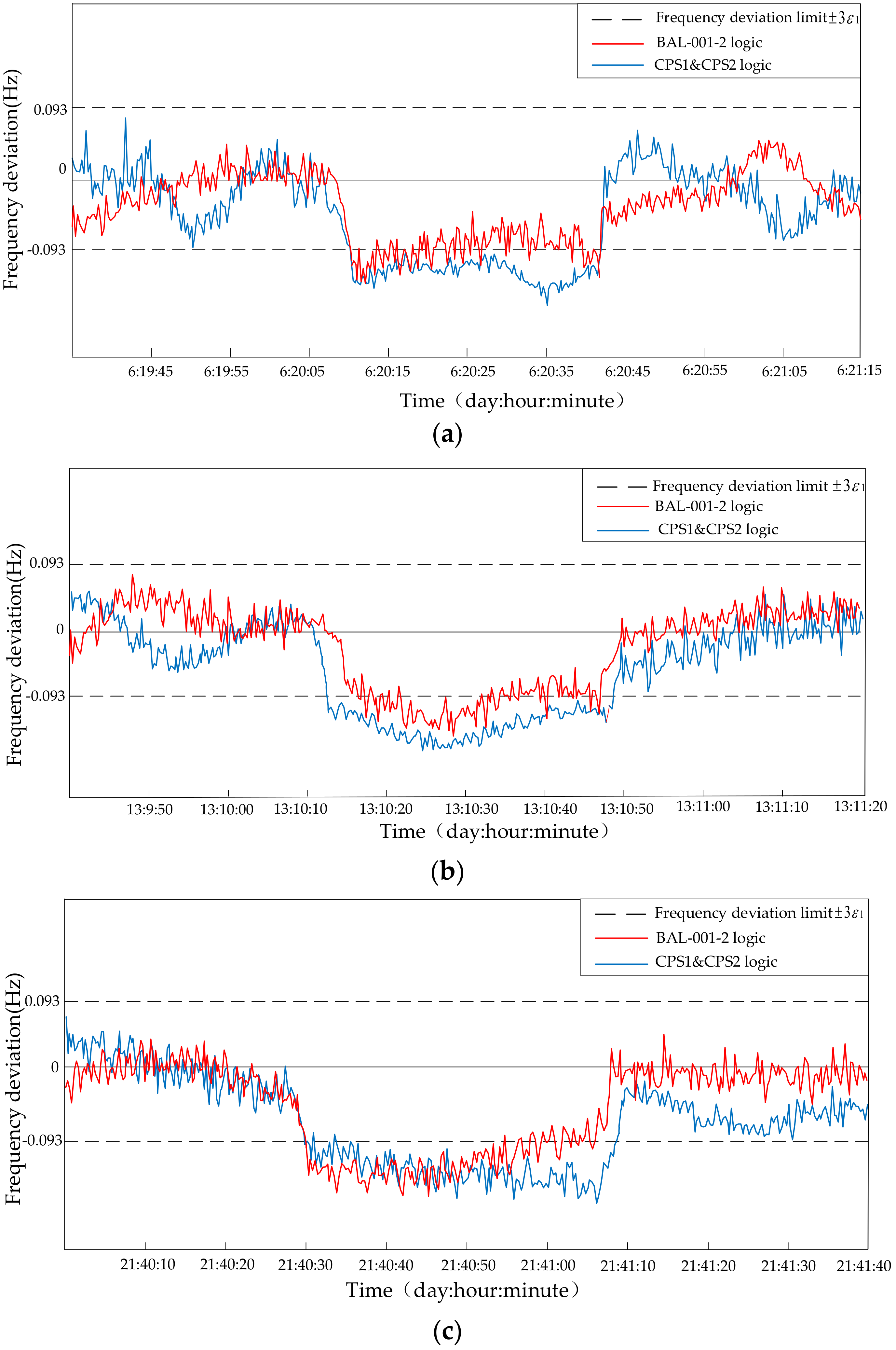
Some test results with the two logics are shown in Table 4. The monthly standard deviation of the frequency deviation with the two logics are both less than the target value shown in Table 3. Thus, both the logics are capable of regulating areas’ actions to meet the CPS1 requirement to maintain long-term frequency quality. However, with the CPS1&CPS2 logic, there are three occurrences when over-limit frequency lasts for more than 30 min. This supports the theoretical proposition that the CPS1&CPS2 logic cannot maintain short-term frequency quality. With the BAL-001-2 logic, there are no occurrences when the frequency exceeds the limit for over 30 min. This shows that the proposed TM-GR logic is able to meet the BAAL Standard requirement.
Figure 6 shows the three occurrences when over-limit frequency deviation lasts for over 30 min with the CPS1&CPS2 logic. Additionally, the frequency deviation performance with the BAL-001-2 logic during the same period is shown in this figure as well. The horizontal axis “x: y: z” represents the time of “day: hour: minute” in the test. As shown in Figure 6a, the frequency deviation with the CPS1&CPS2 logic remains below −3ε1 from “day6: hour20: minute10” to “day6: hour20: minute43”. With the Bal-001-2 logic, it only takes about four minutes to restore the frequency to the secure range.
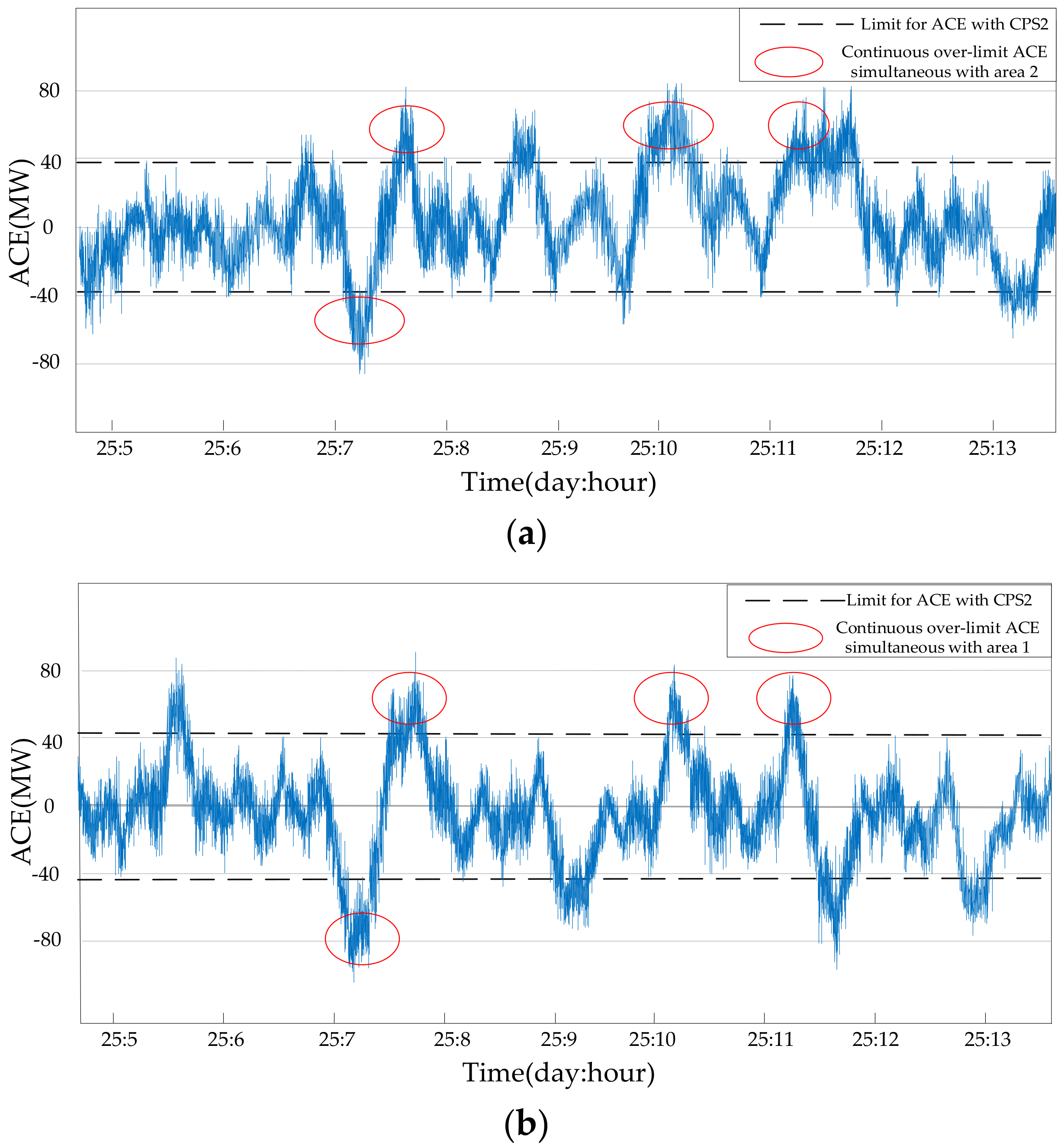
Frequency deviation is due to real power imbalance. The ACE is calculated by the difference between the load demand and all units’ output, so it can reflect the value of real power imbalance. Figure 7 shows the output of different units in two areas with the CPS1&CPS2 logic and the BAL-001-2 logic. The case that the two areas’ ACEs with the CPS1&CPS2 logic remain below or above their own limits during the same period causes the conditions shown in Figure 6. The limits for their ACEs are calculated based on the CPS2 requirement [10]. Figure 8 shows the fluctuations of the two areas’ ACEs with the CPS1&CPS2 logic from “day25: hour5” to “day25: hour13”. During this interval, the case described above occurs four times. Not every case will lead to the consecutive over-limit frequency, because the total ACE size may not be large enough. The CPS2 logic ignores the correlations between ACEs [10,66], so it cannot avoid the case that the two ACEs exceed their limits simultaneously. What is more, the CPS2 logic is not designed to monitor ACE fluctuation all the time. The ACE size is restricted at only 90% of the test period [10], and this can result in the occurrence of a consecutively over-limit ACE.
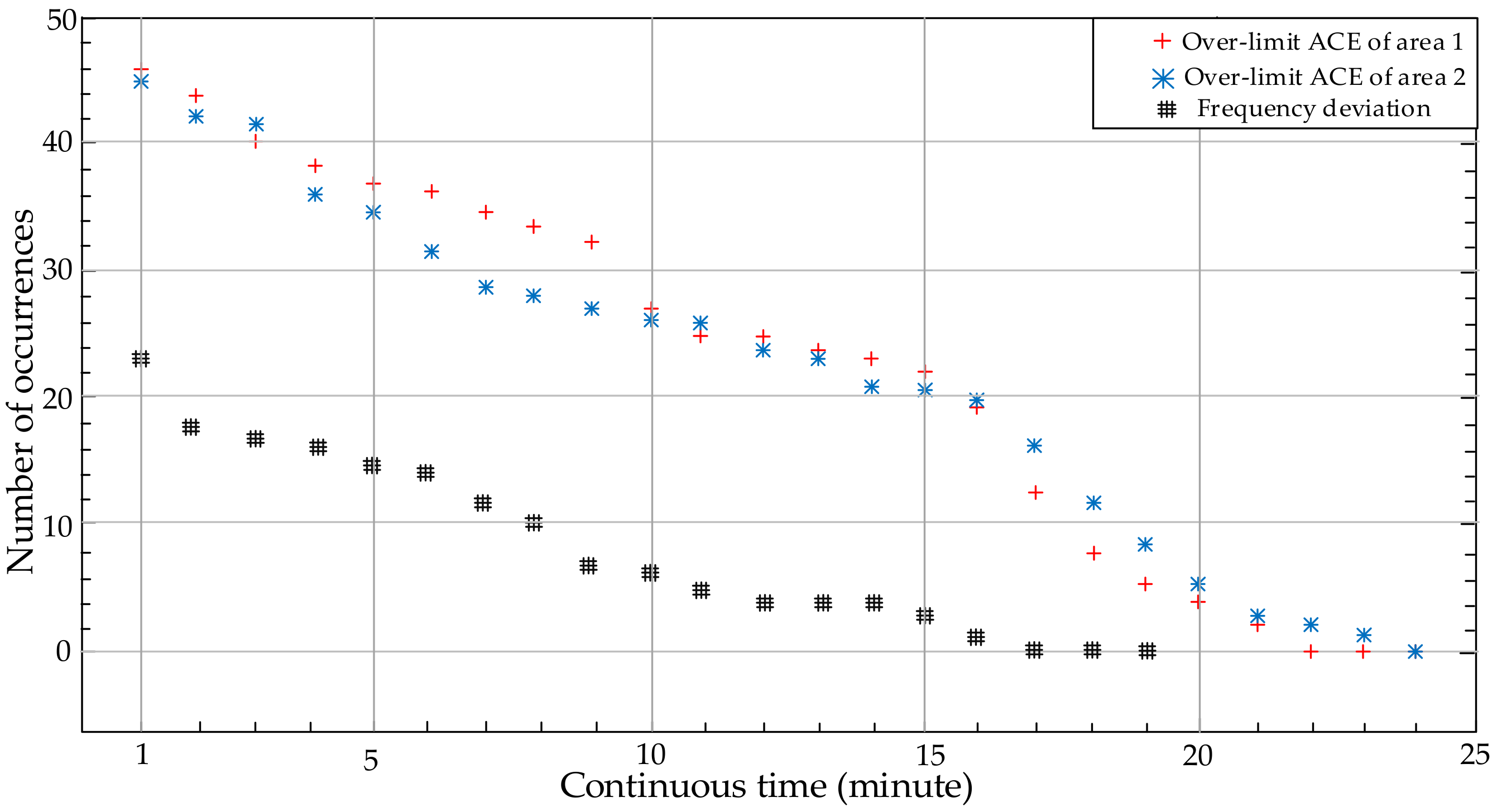
With the BAL-001-2 logic, the distribution of occurrences of different continuous minutes that the over-limit ACE and the over-limit frequency last for is shown in Figure 9. The longest time that the two ACEs remain out of their limits is, respectively, 21 min and 23 min. The longest duration that the over-limit frequency lasts for is 16 min. Thus, the areas’ control performance is considered to meet the Standard BAL-001-2 requirement and the short-time operation security can be maintained as well. These good results are mainly due to the management and regulation of the proposed TM-GR logic.
4.2.3. Regulation on ACE of the BAL-001-2 Logic
The ACE fluctuation of area 2 with the BAL-001-2 logic over some time is shown in Figure 10. When there are no disturbances, the orders to regulate the ACE are given by the CPS1 two-layer logic. To decrease the number of regulation orders and reduce the operation cost, the threshold is often set as a large value, which is decided in the top layer [66]. At the moment of about “day13: hour15: minute25”, the ACE began to decline, which may be caused by a disturbance. After “day13: hour15: minute31”, the ACE rebounded significantly. That moment was supposed to be the triggering moment of the TM-GR logic. From Table 3, the monitoring interval was set to be 3 min. Thus, at “day13: hour15: minute34”, the ACE measurement was checked based on Equations (16) and (18) again. According to the check result, a new order was given to continue to restore the ACE. After “day13: hour15: minute36”, the ACE did not exceed the BAAL any more. The duration of the over-limit ACE was discovered to be 6 clock-minutes, which meets the BAAL Standard requirement.
5. Conclusions
This paper proposes a new control logic, named TM-GR, of wind-area on the new BAAL Standard. Its purpose is to increase the wind power utilization amount, on the premise of maintaining operation security, by taking full advantage of the complementarity between wind power output and load demand. According to an area’s real-time regulating ability and the forecasting results of wind power output, the proposed TM-GR logic sets some triggering moments and monitoring intervals for regulations on ACE. Two different grades of orders to regulate are given based on whether or not the ACE and frequency continuously exceed their limits during the same interval. Only when the frequency deviation is large continuously in the positive direction, which threatens the operation security, a part of the wind turbines will be cut, together with the conventional units’ efforts, to restore frequency quality in a timely manner.
The test results indicate that the proposed logic can give orders to areas at the right triggering moments. The orders can restrict the ACE fluctuation to the controllable range. What is more, the logic can cooperate well with the existing CPS1 logic and has a higher priority than it. The two logics compose the BAL-001-2 logic, which can restrict the duration of over-limit frequency to be less than 30 min and, meanwhile, maintain long-term frequency quality. More significantly, with the proposed BAL-001-2 logic instead of the existing CPS1&CPS2 logic, the wind power curtailment amount will decrease. Thus, the proposed logic is beneficial for reducing the use of fossil energy and the emission of pollutants and would be more popular in practice.
Acknowledgments
This work was supported in part by National Natural Science Foundation of China (Grant No. 51677018) and Project of State Grid Henan Electric Power Company (No. 52170216001D).
Author Contributions
All authors have contributed to this research work. Yekui Chang carried out the main research tasks and wrote the full manuscript. Rao Liu and Yu Ba analyzed and double-checked the results and the whole manuscript. Weidong Li proposed the original ideas.
Conflicts of Interest
The authors declare no conflict of interest.
References
- Pandey, S.K.; Mohanty, S.R.; Kishor, N. A literature survey on load–frequency control for conventional and distribution generation power systems. Renew. Sustain. Energy Rev. 2013, 25, 318–334. [Google Scholar] [CrossRef]
- Rosyiana, F.I.; Kim, J.S.; Song, H. High-Gain Disturbance Observer-Based Robust Load Frequency Control of Power Systems with Multiple Areas. Energies 2017, 10, 595. [Google Scholar] [CrossRef]
- Ersdal, A.M.; Imsland, L.; Uhlen, K. Model predictive load-frequency control. IEEE Trans. Power Syst. 2016, 31, 777–785. [Google Scholar] [CrossRef]
- Liu, Y.; Gao, S.; Zhao, X.; Zhang, N. Coordinated Operation and Control of Combined Electricity and Natural Gas Systems with Thermal Storage. Energies 2017, 10, 917. [Google Scholar] [CrossRef]
- Wen, G.; Hu, G.; Hu, J.; Chen, G. Frequency regulation of source-grid-load systems: A compound control strategy. IEEE Trans. Ind. Inform. 2016, 12, 69–78. [Google Scholar] [CrossRef]
- Ahumada, C.; Cárdenas, R.; Sáez, D.; Guerrero, J.M. Secondary control strategies for frequency restoration in islanded microgrids with consideration of communication delays. IEEE Trans. Smart Grid 2016, 7, 1430–1441. [Google Scholar] [CrossRef]
- Ba, Y.; Liu, R.; Li, W. Comparison of CPS and its assessment between North America and China. Autom. Electr. Power Syst. 2012, 36, 63–72. (In Chinese) [Google Scholar]
- Maruejouls, N.; Margotin, T.; Trotignon, M.; Dupuis, P.L.; Tesseron, J.M. Measurement of the load frequency control system service: Comparison between American and European indicators. IEEE Trans. Power Syst. 2002, 15, 1382–1387. [Google Scholar] [CrossRef]
- Moghadam, M.F.; Dunford, W.G.; Vaahedi, E.; Metcalfe, M. Evaluation of NERC’s BRD frequency control standard in hydroelectric generation. In Proceedings of the Power & Energy Society General Meeting, Denver, CO, USA, 26–30 July 2015; pp. 1–5. [Google Scholar] [CrossRef]
- Jaleeli, N.; VanSlyck, L.S. NERC’s new control performance standards. IEEE Trans. Power Syst. 1999, 14, 1092–1099. [Google Scholar] [CrossRef]
- Steinmetz, W.K.; Cole, J.D. Sampling ACE data for NERC CPC surveys. IEEE Comput. Appl. Power 1993, 6, 27–32. [Google Scholar] [CrossRef]
- Jaleeli, N.; VanSlyck, L.S. Control Performance Standards and Procedures for Interconnected Operation; Technical Report TR-107813; Electric Power Research Institute: Palo Alto, CA, USA, 1997. [Google Scholar]
- BAL-001-2—Real Power Balancing Control Performance Standard Background Document. Available online: http://www.nerc.com/pa/Stand/Project%202010141%20%20Phase%201%20of%20Balancing%20Authority%20Re/BAL-001-2_Background_%20Document-Clean-20130701.pdf (accessed on 7 November 2017).
- Frequency Control Performance Measurement and Requirements. Available online: http://escholarship.org/uc/item/2d63w2f7 (accessed on 7 November 2017).
- Etingov, P.V.; Makarov, Y.V.; Samaan, N.; Ma, J.; Loutan, C.; Rothleder, M.; Chowdhury, S. Prediction of regulation reserve requirements in california ISO balancing authority area based on BAAL. In Proceedings of the Power and Energy Society General Meeting, Vancouver, BC, Canada, 21–25 July 2013; pp. 1–5. [Google Scholar] [CrossRef]
- Balancing Authority ACE Limit (BAAL) Preliminary Field Trial Report. Available online: http://www.nerc.com/FilingsOrders/us/NERC%20Filings%20to%20FERC%20DL/Transmittal_letter_Field%20Trial%20Report.pdf (accessed on 7 November 2017).
- Reliability Standards for the Bulk Electric Systems of North America. Available online: http://www.nerc.com/pa/Stand/Reliability%20Standards%20Complete%20Set/RSCompleteSet.pdf (accessed on 7 November 2017).
- Rerkpreedapong, D.; Hasanovic, A.; Feliachi, A. Robust load frequency control using genetic algorithms and linear matrix inequalities. IEEE Trans. Power Syst. 2003, 18, 855–861. [Google Scholar] [CrossRef]
- Yu, T.; Zhou, B. A novel self-tuning CPS controller based on Q-learning method. In Proceedings of the Power and Energy Society General Meeting, Pittsburgh, PA, USA, 20–24 July 2008; pp. 1–6. [Google Scholar] [CrossRef]
- Merk, B.; Litskevich, D.; Whittle, K.R.; Bankhead, M.; Taylor, R.J.; Mathers, D. On a Long Term Strategy for the Success of Nuclear Power. Energies 2017, 10, 867. [Google Scholar] [CrossRef]
- Elamalayil, S.D.; Leijon, M. Cross-Regulation Assessment of DIDO Buck-Boost Converter for Renewable Energy Application. Energies 2017, 10, 846. [Google Scholar] [CrossRef]
- Cong, P.; Tang, W.; Zhang, L.; Zhang, B.; Cai, Y. Day-Ahead Active Power Scheduling in Active Distribution Network Considering Renewable Energy Generation Forecast Errors. Energies 2017, 10, 1291. [Google Scholar] [CrossRef]
- Weitemeyer, S.; Kleinhans, D.; Vogt, T.; Agert, C. Integration of Renewable Energy Sources in future power systems: The role of storage. Renew. Energy 2015, 75, 14–20. [Google Scholar] [CrossRef]
- Kaplan, Y.A. Overview of wind energy in the world and assessment of current wind energy policies in Turkey. Renew. Sustain. Energy Rev. 2015, 43, 562–568. [Google Scholar] [CrossRef]
- Liu, Y.; Ren, L.; Li, Y.; Zhao, X. The industrial performance of wind power industry in China. Renew. Sustain. Energy Rev. 2015, 43, 644–655. [Google Scholar] [CrossRef]
- Higgins, P.; Foley, A. The evolution of offshore wind power in the United Kingdom. Renew. Sustain. Energy Rev. 2014, 37, 599–612. [Google Scholar] [CrossRef]
- François, B.; Martino, S.; Tøfte, L.S.; Hingray, B.; Mo, B.; Creutin, J. Effects of Increased Wind Power Generation on Mid-Norway’s Energy Balance under Climate Change: A Market Based Approach. Energies 2017, 10, 227. [Google Scholar] [CrossRef]
- Global Wind Report. 2016. Available online: https://www.researchgate.net/p-ublication/316699909_Global_Wind_Report_2016_-_Annual_Market_Update (accessed on 7 November 2017).
- Dimov, A.; Bolik, S. Wind turbine manufacturers observation regarding reactive power support and control requirements. IET Renew. Power Gener. 2017, 11, 539–544. [Google Scholar] [CrossRef]
- Kane, L.; Ault, G.W. Evaluation of wind power curtailment in active network management schemes. IEEE Trans. Power Syst. 2015, 30, 672–679. [Google Scholar] [CrossRef]
- Fan, X.; Wang, W.; Shi, R.; Li, F. Analysis and countermeasures of wind power curtailment in China. Renew. Sustain. Energy Rev. 2015, 52, 1429–1436. [Google Scholar] [CrossRef]
- Burke, D.J.; O’Malley, M.J. Factors influencing wind energy curtailment. IEEE Trans. Sustain. Energy 2011, 2, 185–193. [Google Scholar] [CrossRef]
- Gu, Y.; Xie, L.; Rollow, B.; Hesselbaek, B. Congestion-induced wind curtailment: Sensitivity analysis and case studies. In Proceedings of the North American Power Symposium, Boston, MA, USA, 4–6 August 2011; pp. 1–7. [Google Scholar] [CrossRef]
- Jacobsen, H.K.; Schröder, S.T. Curtailment of renewable generation: Economic optimality and incentives. Energy Policy 2012, 49, 663–675. [Google Scholar] [CrossRef] [Green Version]
- Martín-Martínez, S.; Gómez-Lazaro, E.; Molina-Garcia, A.; Honrubia-Escribano, A. Impact of wind power curtailments on the Spanish power system operation. In Proceedings of the PES General Meeting|Conference & Exposition, National Harbor, MD, USA, 27–31 July 2014; pp. 1–5. [Google Scholar] [CrossRef]
- Luo, G.L.; Li, Y.L.; Tang, W.J.; Wei, X. Wind curtailment of China’s wind power operation: Evolution, causes and solutions. Renew. Sustain. Energy Rev. 2016, 53, 1190–1201. [Google Scholar] [CrossRef]
- Xiong, W.; Wang, Y.; Mathiesen, B.V.; Zhang, X. Case study of the constraints and potential contributions regarding wind curtailment in Northeast China. Energy 2016, 110, 55–64. [Google Scholar] [CrossRef]
- Garrigle, E.V.M.; Deane, J.P.; Leahy, P.G. How much wind energy will be curtailed on the 2020 Irish power system? Renew. Energy 2013, 55, 544–553. [Google Scholar] [CrossRef]
- Mckenna, E.; GrüNewald, P.; Thomson, M. Going with the wind: Temporal characteristics of potential wind curtailment in Ireland in 2020 and opportunities for demand response. IET Renew. Power Gener. 2015, 9, 66–77. [Google Scholar] [CrossRef]
- Alessandrini, S.; Sperati, S.; Pinson, P. A comparison between the ECMWF and COSMO Ensemble Prediction Systems applied to short-term wind power forecasting on real data. Appl. Energy 2013, 107, 271–280. [Google Scholar] [CrossRef]
- Dvorkin, Y.; Lubin, M.; Backhaus, S.; Chertkov, M. Uncertainty sets for wind power generation. IEEE Trans. Power Syst. 2016, 31, 3326–3327. [Google Scholar] [CrossRef]
- Bessa, R.J.; Miranda, V.; Botterud, A.; Wang, J.; Constantinescu, E.M. Time adaptive conditional kernel density estimation for wind power forecasting. IEEE Trans. Sustain. Energy 2012, 3, 660–669. [Google Scholar] [CrossRef]
- Wan, C.; Xu, Z.; Pinson, P.; Dong, Z.; Wong, K. Probabilistic forecasting of wind power generation using extreme learning machine. IEEE Trans. Power Syst. 2014, 29, 1033–1044. [Google Scholar] [CrossRef]
- Constantinescu, E.M.; Zavala, V.M.; Rocklin, M.; Lee, S.; Anitescu, M. A computational framework for uncertainty quantification and stochastic optimization in unit commitment with wind power generation. IEEE Trans. Power Syst. 2011, 26, 431–441. [Google Scholar] [CrossRef]
- Wan, C.; Lin, J.; Wang, J.; Song, Y.; Dong, Z. Direct quantile regression for nonparametric probabilistic forecasting of wind power generation. IEEE Trans. Power Syst. 2017, 32, 2767–2778. [Google Scholar] [CrossRef]
- Ackermann, T. Wind Power in Power Systems, 2rd ed.; John Wiley & Sons Ltd.: New York, NY, USA, 2012. [Google Scholar]
- Bianchi, F.D.; Mantz, R.J.; De Battista, H. The Wind and Wind Turbines; Springer: London, UK, 2007; pp. 7–28. [Google Scholar]
- Liu, J.; Wang, X.; Lu, Y. A novel hybrid methodology for short-term wind power forecasting based on adaptive neuro-fuzzy inference system. Renew. Energy 2017, 103, 620–629. [Google Scholar] [CrossRef]
- Fang, S.; Chiang, H.D. A high-accuracy wind power forecasting model. IEEE Trans. Power Syst. 2017, 32, 1589–1590. [Google Scholar] [CrossRef]
- Jallad, J.; Mekhilef, S.; Mokhlis, H. Frequency Regulation Strategies in Grid Integrated Offshore Wind Turbines via VSC-HVDC Technology: A Review. Energies 2017, 10, 1244. [Google Scholar] [CrossRef]
- Arani, M.F.M.; Mohamed, Y.A.R.I. Analysis and Damping of Mechanical Resonance of Wind Power Generators Contributing to Frequency Regulation. IEEE Trans. Power Syst. 2017, 32, 3195–3204. [Google Scholar] [CrossRef]
- Alves, R.; Reis, F.S.; Shen, H. Wind power curtailment optimization for day-ahead operational planning. In Proceedings of the PES Innovative Smart Grid Technologies Conference Europe (ISGT-Europe), Ljubljana, Slovenia, 9–12 October 2016; pp. 1–6. [Google Scholar] [CrossRef]
- Waite, M.; Modi, V. Modeling wind power curtailment with increased capacity in a regional electricity grid supplying a dense urban demand. Appl. Energy 2016, 183, 299–317. [Google Scholar] [CrossRef]
- Supporting Document for the Network Code on Load-Frequency Control and Reserves. Available online: https://www.entsoe.eu/fileadmin/user_upload/_library/resources/LCFR/130628-NC_LFCR-Supporting_Document-Issue1.pdf (accessed on 7 November 2017).
- Network Code on Load-Frequency Control and Reserves. Available online: https://www.entsoe.eu/fileadmin/user_upload/_library/resources/LCFR/130628-NC_LFCR-Issue1.pdf (accessed on 7 November 2017).
- Tan, C.; Dai, Z.; Teng, X.; Gao, Z. Development of Frequency Control Performance Standard in North America and Its Enlightenment to China. Autom. Electr. Power Syst. 2015, 39, 1–7. [Google Scholar] [CrossRef]
- Chang, Y.; Liu, R.; Ba, Y.; Li, W. Analysis of Balancing Authority ACE Limit Standard of North America. Power Syst. Technol. 2016, 1, 256–262. [Google Scholar] [CrossRef]
- Underfrequency Load Shedding Assessment Report. Available online: https://www.wecc.biz/Reliability/UFLSRG (accessed on 7 November 2017).
- IEEE Guide for Abnormal Frequency Protection for Power Generating Plants. Available online: http://ieeexplore.ieee.org/document/1270518/ (accessed on 7 November 2017).
- Walling, R.A.; Miller, N.W. Distributed generation islanding-implications on power system dynamic performance. In Proceedings of the Power Engineering Society Summer Meeting, Chicago, IL, USA, 21–25 July 2002; pp. 92–96. [Google Scholar] [CrossRef]
- Anderson, P.M.; Mirheydar, M. An adaptive method for setting underfrequency load shedding relays. IEEE Trans. Power Syst. 1992, 7, 647–655. [Google Scholar] [CrossRef]
- Aho, J.; Buckspan, A.; Laks, J.; Fleming, P.; Jeong, Y.; Dunne, F.; Churchfield, M.; Pao, L.; Johnson, K. A tutorial of wind turbine control for supporting grid frequency through active power control. In Proceedings of the American Control Conference, Montreal, QC, Canada, 27–29 June 2012; pp. 3120–3131. [Google Scholar] [CrossRef]
- Rawn, B.G.; Lehn, P.W.; Maggiore, M. Control methodology to mitigate the grid impact of wind turbines. IEEE Trans. Energy Convers. 2007, 22, 431–438. [Google Scholar] [CrossRef]
- Tarnowski, G.C.; Kjær, P.C.; Dalsgaard, S.; Nyborg, A. Regulation and frequency response service capability of modern wind power plants. In Proceedings of the Power & Energy Society General Meeting, Providence, RI, USA, 25–29 July 2010; pp. 1–8. [Google Scholar] [CrossRef]
- Dvorkin, Y.; Ortega-Vazuqez, M.A.; Kirschen, D.S. Wind generation as a reserve provider. IET Gener. Transm. Distrib. 2015, 9, 779–787. [Google Scholar] [CrossRef]
- Yao, M.; Shoults, R.R.; Kelm, R. AGC logic based on NERC’s new Control Performance Standard and Disturbance Control Standard. IEEE Trans. Power Syst. 2000, 15, 852–857. [Google Scholar] [CrossRef]
- Wu, S.S.J.; Chang-Chien, L.R.; Lee, W.J.; Lu, C.N.; Chang, R.F.; Wu, C.C.; Lan, H.W. Redesign of frequency controls for CPS evaluations in an isolated power system. In Proceedings of the Power and Energy Society General Meeting, Providence, RI, USA, 25–29 July 2010; pp. 1–6. [Google Scholar] [CrossRef]
- Ba, Y.; Li, W. A simulation scheme for AGC relevant studies. IEEE Trans. Power Syst. 2013, 28, 3621–3628. [Google Scholar] [CrossRef]
- Yi, H.; Cheng, S.; Du, Z.; Shi, L.; Ni, Y. Modeling and simulation on long-term dynamics of interconnected power system using area COI concept. Electr. Power Syst. Res. 2008, 78, 1369–1377. [Google Scholar] [CrossRef]
- Zhang, N. Multi-Cycle Unit Commitment Coping with High Wind Power Uncertainty. Ph.D. Thesis, Dalian University of Technology, Dalian, China, June 2014. [Google Scholar]
Figure 1.
Requirement for Area Control Error (ACE) in the BAAL Standard.
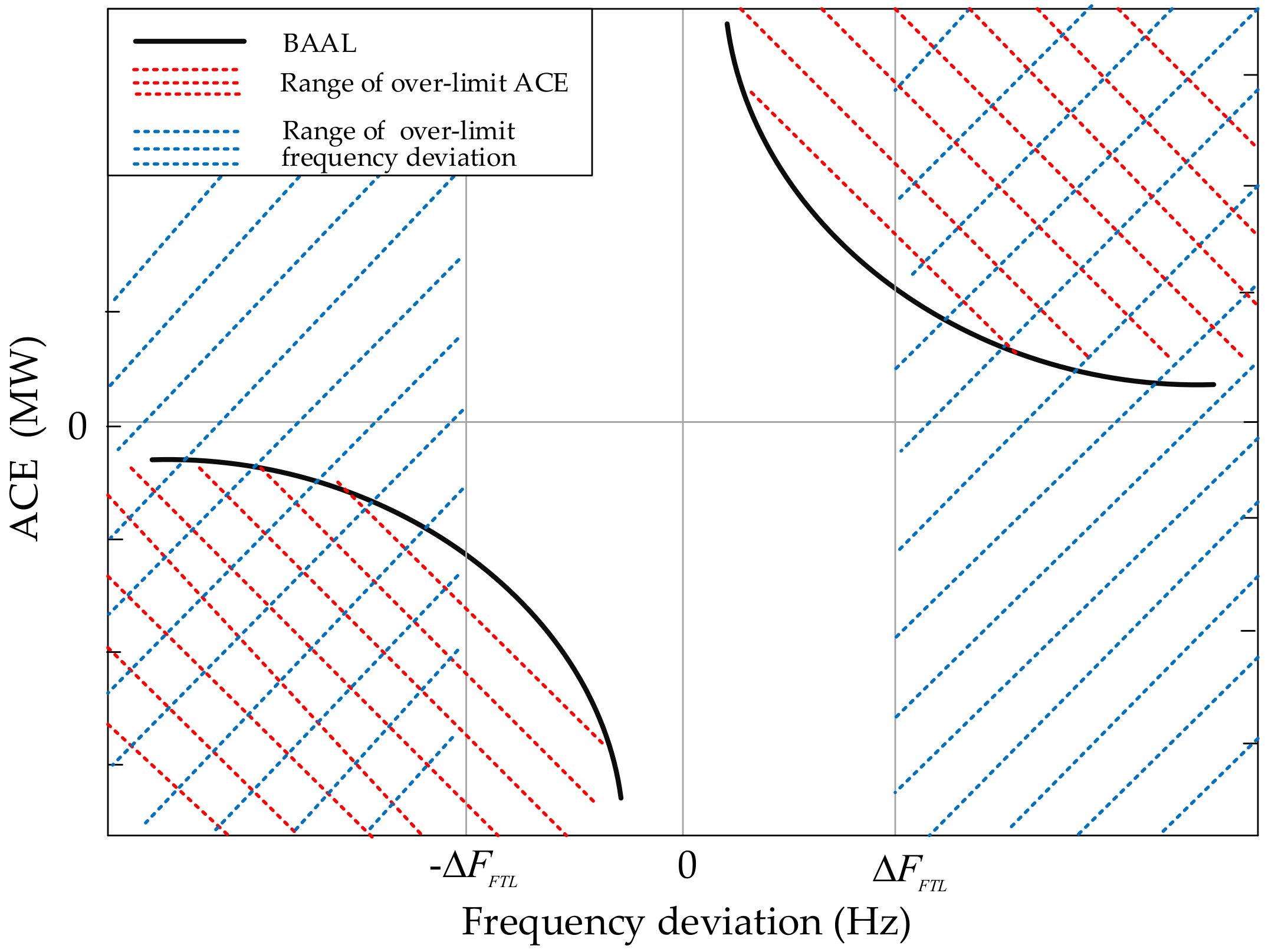
Figure 2.
Different ACE fluctuations after the triggering moment: (a) negative frequency deviation; (b) positive frequency deviation.
Figure 2.
Different ACE fluctuations after the triggering moment: (a) negative frequency deviation; (b) positive frequency deviation.

Figure 3.
Framework of the cooperation between the Triggered Monitoring and Graded Regulation (TM-GR) logic and the Control Performance Standard 1 (CPS1) control logic.
Figure 3.
Framework of the cooperation between the Triggered Monitoring and Graded Regulation (TM-GR) logic and the Control Performance Standard 1 (CPS1) control logic.
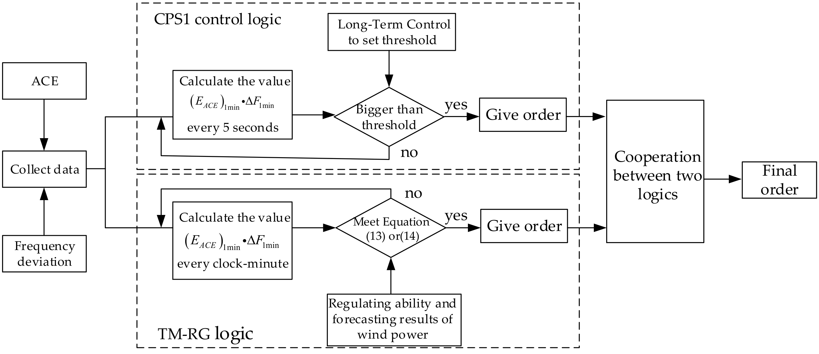
Figure 4.
Wind power utilization with the two logics.

Figure 5.
Distribution of days in different ranges of daily wind power utilization rate with the two logics.
Figure 5.
Distribution of days in different ranges of daily wind power utilization rate with the two logics.

Figure 6.
Three conditions of frequency deviation fluctuation with the CPS1&CPS2 logic and the BAL-001-2 logic: (a) condition 1; (b) condition 2; (c) condition 3.
Figure 6.
Three conditions of frequency deviation fluctuation with the CPS1&CPS2 logic and the BAL-001-2 logic: (a) condition 1; (b) condition 2; (c) condition 3.

Figure 7.
Output of different generation units in two areas with two logics: (a) the CPS1&CPS2 logic; (b) the BAL-001-2 logic.
Figure 7.
Output of different generation units in two areas with two logics: (a) the CPS1&CPS2 logic; (b) the BAL-001-2 logic.
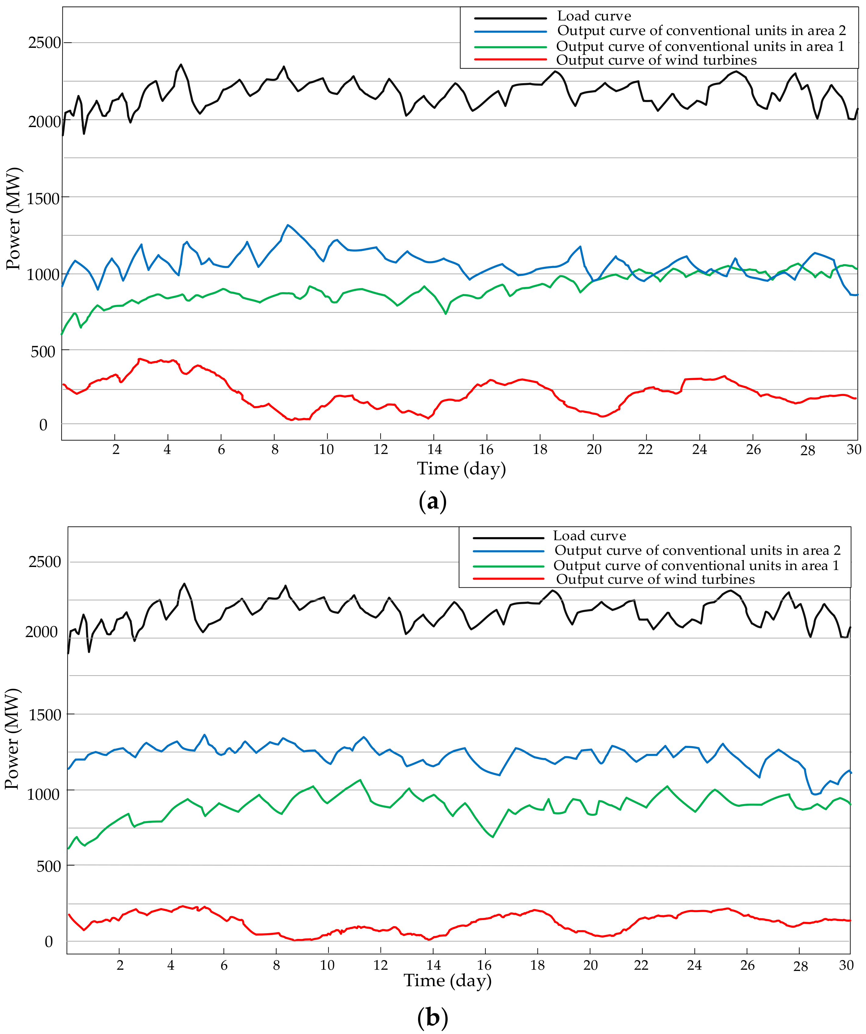
Figure 8.
Two ACEs’ fluctuations during some time with the CPS1&CPS2 logic: (a) area 1; (b) area 2.

Figure 9.
Occurrences of over-limit frequency and over-limit ACE for different continuous minutes.

Figure 10.
ACE fluctuation of area 2 over some time with the BAL-001-2 control logic.

Table 1.
Violation severity level of the Balancing Authority Area Control Error (ACE) Limit (BAAL) Standard.
Table 1.
Violation severity level of the Balancing Authority Area Control Error (ACE) Limit (BAAL) Standard.
| Violation Level | Description |
|---|---|
| Low | Duration of over-limit ACE is between 30 min and 45 min |
| Moderate | Duration of over-limit ACE is between 45 min and 60 min |
| High | Duration of over-limit ACE is between 60 min and 75 min |
| Severe | Duration of over-limit ACE is larger than 75 min |
Table 2.
Control actions under different conditions.
| Condition Number | Description of Different Conditions | Control Actions |
|---|---|---|
| 1 | The ACE doses not exceed the BAAL any more. | Clear orders. |
| 2 | Equation (12) or Equation (13) is not met at the end of . ( is replaced by ) | Clear orders and continue monitoring ACE. |
| 3 | Equation (16) or Equation (17) is met at the end of . ( is replaced by ) | Regard as a new triggering moment to give orders. |
| 4 | Equation (18) or Equation (19) is met at the end of . ( is replaced by ) | Regard as a new triggering moment to give orders. Start contingency reserve or cut wind turbines. |
Table 3.
Control actions under different conditions.
| Parameter | Description | Value |
|---|---|---|
| Scheduled frequency | 50 (Hz) | |
| Target standard deviation of one-minute average frequency deviation | 0.031 (Hz) | |
| Target standard deviation of ten-minute average frequency deviation | 0.0098 (Hz) | |
| Frequency bias coefficients of two areas | , | −150, −200 (MW/0.1 Hz) |
| Total installed capacity of conventional units in two areas | , | 2500, 3500 (MW) |
| Total installed capacity of wind power in area 1 | 500 (MW) | |
| Monitoring interval | 3 (min) | |
| Margin coefficient | 0.9 | |
| Regulating rate of conventional units in area 1 | , | 4% () |
| Regulating rate of conventional units in area 2 | , | 3% () |
| Regulation coefficient, Enhanced regulation coefficient | , | 0.95, 1.2 |
Table 4.
Control actions under different conditions.
| Type of Control Logic | Monthly Wind Power Curtailment Rate | Average Daily Wind Power Utilization Rate | Number of Times of over-Limit Frequency for over 30 Consecutive Minutes | Monthly Standard Deviation of Frequency Deviation |
|---|---|---|---|---|
| CPS1&CPS2 | 19.6% | 21.8% | 3 | 0.021 (Hz) |
| BAL-001-2 | 6.3% | 7.4% | 0 | 0.028 (Hz) |
© 2018 by the authors. Licensee MDPI, Basel, Switzerland. This article is an open access article distributed under the terms and conditions of the Creative Commons Attribution (CC BY) license (http://creativecommons.org/licenses/by/4.0/).
Share and Cite
MDPI and ACS Style
Chang, Y.; Liu, R.; Ba, Y.; Li, W. A New Control Logic for a Wind-Area on the Balancing Authority Area Control Error Limit Standard for Load Frequency Control. Energies 2018, 11, 121. https://doi.org/10.3390/en11010121
AMA Style
Chang Y, Liu R, Ba Y, Li W. A New Control Logic for a Wind-Area on the Balancing Authority Area Control Error Limit Standard for Load Frequency Control. Energies. 2018; 11(1):121. https://doi.org/10.3390/en11010121
Chicago/Turabian StyleChang, Yekui, Rao Liu, Yu Ba, and Weidong Li. 2018. "A New Control Logic for a Wind-Area on the Balancing Authority Area Control Error Limit Standard for Load Frequency Control" Energies 11, no. 1: 121. https://doi.org/10.3390/en11010121
Note that from the first issue of 2016, this journal uses article numbers instead of page numbers. See further details here.