Article

Coordinated Control Schemes of Super-Capacitor and Kinetic Energy of DFIG for System Frequency Support

1
School of Automation, Nanjing Institute of Technology, Nanjing 211167, China
2
School of Electrical Engineering, Xi’an Jiaotong University, Xi’an 710049, China
3
School of Internet of Things Engineering, Jiangnan University, Wuxi 214122, China
4
School of Electric Power, South China University of Technology, Guangzhou 510006, China
5
Guangdong Key Laboratory of Clean Energy Technology, Guangzhou 510640, China
*
Author to whom correspondence should be addressed.
Energies 2018, 11(1), 103; https://doi.org/10.3390/en11010103
Submission received: 19 November 2017 / Revised: 21 December 2017 / Accepted: 22 December 2017 / Published: 3 January 2018
(This article belongs to the Section F: Electrical Engineering)

Abstract

:
This paper mainly focuses on how to provide frequency supports by the doubly fed induction generator (DFIG) during system disturbances. Two coordinated controls that enable system frequency supports by DFIG-based wind turbines (WTs) are proposed in this paper. The first control scheme seeks to render system support via simultaneously utilizing the energy from the installed super-capacitor between the back-to-back converter of DFIG, and WT rotational kinetic energy (KE). The second one stabilizes system frequency by firstly exerting the installed super-capacitor energy and then WT rotational KE via a unique cascading control. Both proposed coordinated control schemes jointly utilize two virtual inertia sources, namely super-capacitor in the DFIG and rotor rotational mass in the WT to fast provide system frequency support. However, the second proposed one stands itself out by reducing its impaired impacts on the overall wind energy production. Two proposed controls on rapidly providing frequency support are effectively verified and compared in detail by different system disturbances in the DIgSILENT/Powerfactory software.

1. Introduction

In recent years, the penetration of wind energy into power systems has grown rapidly, which raises great concerns about the security and reliable operation of power systems. One challenge is the reduced system inertia due to the high wind power penetration [1,2,
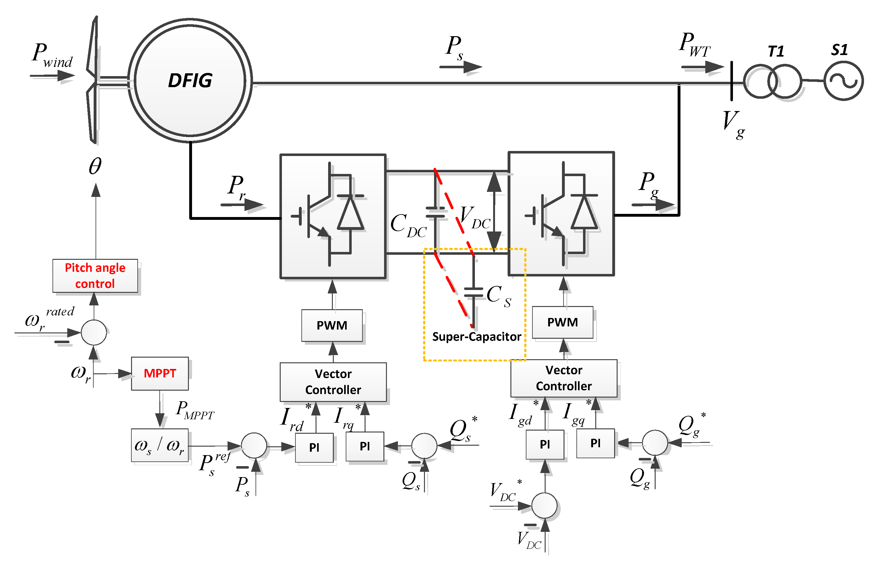
3]. Unlike the conventional synchronous machine, increasing variable speed wind turbines (WTs) are connected to the power grid via back-to-back power electronic devices. The main function of these converters is to maximize harvest wind energy, and make sure of the normal power transmission. With this control logic, WTs rotational speed and the system frequency are effectively decoupled. Correspondingly, the system disturbance that would result in the system frequency excursion can somewhat only be smoothed by the synchronous generator (SG) available in the power systems [4,5]. To improve the inertia level of high wind power penetration system, many countries have requested WTs to contribute to the system inertia or frequency response in the national grid codes [6,7].
To face with the wind random and intermittent nature, and provide related system inertia or frequency support from WT, one direct solution is to utilize energy storage system (ESS), such as pumped water, flying wheel devices, compressed air, and batteries, which can smooth the active power generation from WTs or emulate the power-frequency curve as conventional SG to stabilize system frequency [8,9,10]. However, there are significant concerns from both technical and economic perspectives that may prevent wide use of these technologies. In addition, ESS technologies may not be economical considering charging and discharging losses, high installation investment, and relatively low life cycles. Therefore, it is necessary to investigate new control schemes that can fully utilize the self-potentials of WTs.
In fact, totally, three separated resources in wind conversion system can be used for enabling to provide fast system support. Firstly, the partially reserved wind energy by blade pitching of WT [11,12,
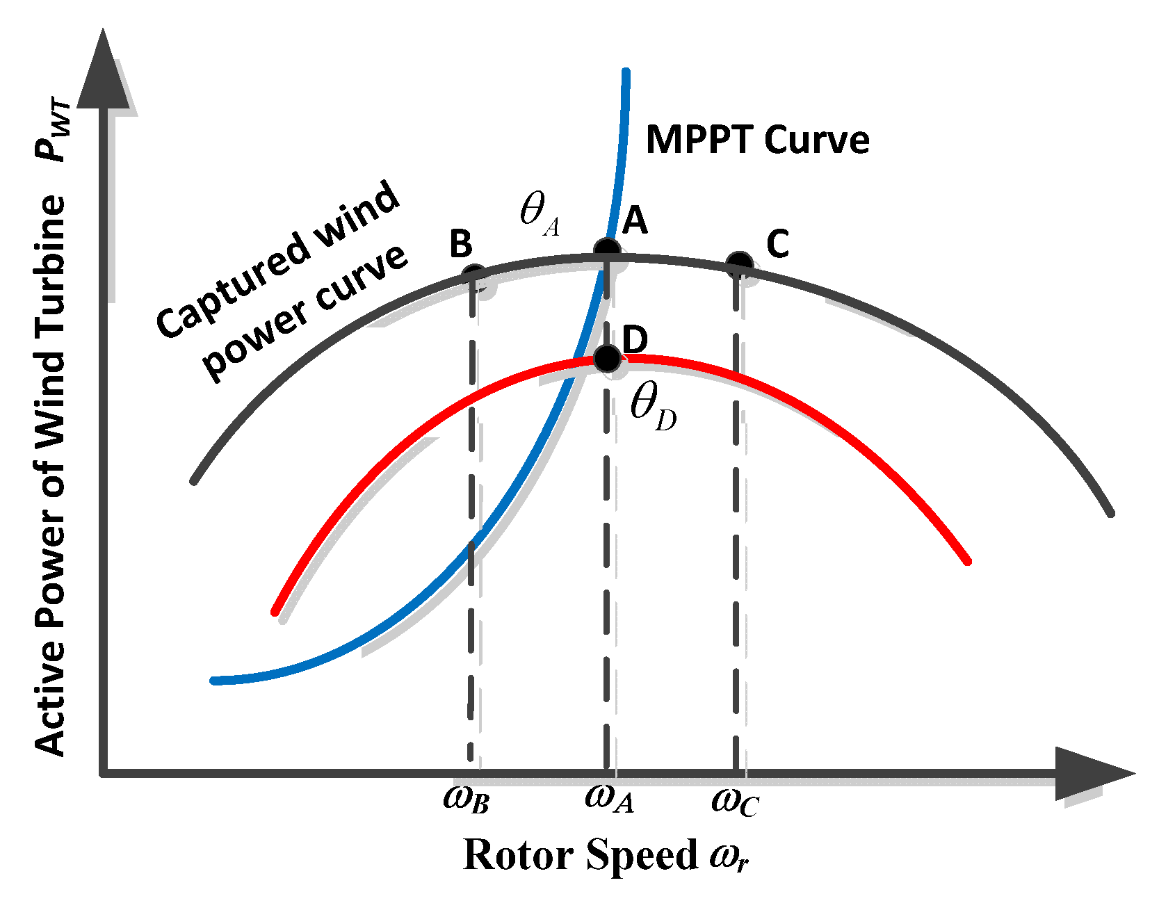
13] can be utilized to stabilize the grid frequency. This scheme requires WTs not to operate at their maximal power tracking point, which enables WTs to release partial reserved energy by increasing pitch angle or curtail excessive wind energy by decreasing pitch angle when system needs. Therefore, significant wind energy will be compromised through pitch angle control of WT. In addition, the control speed is comparably slow due to the mechanical regulation process involved, and the frequent utilization of blade pitching will increase the mechanical stress of WT and the fatigue of WT will frequently happen.
The second widely used solution is the rotational kinetic energy (KE) of WT rotor mass, which can well stabilize the grid frequency through the proper control design of the so-called emulated inertia control [14,15,16,17,18,19,20,21,
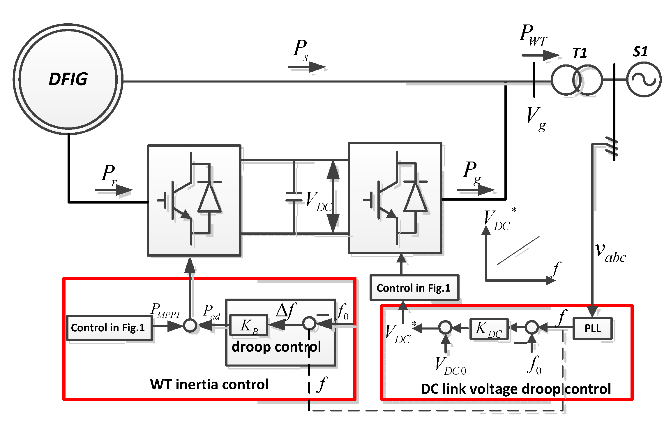
22]. In general, when detecting the grid frequency excursion, the set-point of WT generation reference will be accordingly changed. Sequentially, partially rotational energy of the WT rotor will be released via rotor speed deceleration when there is a generation shortage of the system or more wind energy will be temporarily stored in WT rotor via rotor speed acceleration when there is a load scarcity of the system. Broadly, the so-called emulated inertia control has three main methodologies including droop control which is based on the system frequency deviation [14,15,16,17], derivation control [18,19,20] which is activated when detecting the change of the system frequency derivation and deloading control [21,22] by defined frequency power curve by shifting the WT operation status from MPPT. The main advantage of the derivation control is that it can emulate the inertia response of traditional SG very well, but it will easily lead to the grid instability with the noise in the grid frequency measurement. In [17], the droop control is regarded as an effective inertia response scheme of WT for supporting system frequency.
The last solution that can be used for system frequency support is the DC-link self-capacitor energy of DFIG based WT. It is feasible for DFIG to temporarily increase or decrease DC-link voltage that partial DC capacitor energy can be utilized for system support. In [23], a combined control by together utilization of the DC capacitor energy and reserved energy by blade pitching of the permanent magnetic SG for WT generation smoothing was proposed. Arani et al. [24] pointed out the WT rotational mass and small capacitor of DFIG can be regarded as two important virtual inertia for DFIG based WT. Since the electrical energy stored in the DC-link capacitor is comparably small, a more economical solution is to install a super-capacitor to the back-to-back converter of DFIG to obtain large WT virtual inertia constant in this paper.
In the existing literatures, the main focuses have been drawn on the use of two afore-mentioned resources, namely, rotational rotor mass of DFIG and DC-link self-capacitor (super-capacitor based) separately for fast system support. However, how to jointly coordinate them to stabilize the grid frequency is not well investigated in the previous literatures.
Two controls on rapidly providing inertia support to fully use WT’s self-potential to provide the system support are proposed in this paper. The first scheme seeks to together use the energy from the installed super-capacitor and the WT rotational KE for system support. However, it needs WT to deviate from MPPT status constantly once the frequency disturbance happens, which is not a cost-effective scheme for wind farms. Accordingly, the second control implements a cascaded control structure to exert the energy from the installed super-capacitor firstly and then the KE from WT rotational mass to stabilize the system frequency, and it has an outstanding merit with minimizing the impaired impacts on energy production.

2. Conventional Control of DFIG

This section mainly describes some basic knowledge. In this paper, DFIG-based WT is utilized as a classical wind generation type to demonstrate the proposed control scheme. The detailed model of the DFIG based WT and its classical control are briefly introduced [25]. Then, the WT model is accordingly introduced.

2.1. Dynamic Model of Induction Generator

The detailed dynamic model of the complete DFIG system in this paper can be referred to [4,26,27], including the induction generator model, the drive train model, the back-to back converter model and the controller model. The controller of the complete DFIG system mainly contains the rotor-side converter (RSC) controller, the grid-side converter (GSC) controller and the pitch angle controller, which will be introduced in the following sections.
The dynamic model of the induction generator in d-q frame is given by [4],
{ u ds = R s i ds ω s ψ qs + 1 ω b d ψ ds d t u qs = R s i qs ω s ψ ds + 1 ω b d ψ qs d t u dr = R r i dr ( ω s ω r ) ψ qr + 1 ω b d ψ dr d t u qr = R r i qr + ( ω s ω r ) ψ dr + 1 ω b d ψ qr d t ,
where ids, iqs and idr, iqr are the stator current and the rotor current in d-q frame, respectively. uds, uqs and udr, uqr are the stator voltage and the rotor voltage in d-q frame, respectively. ψds, ψqs and ψdr, ψqr are the stator flux and the rotor flux in d-q frame, respectively. ωb, ωs, and ωr are the base, stator, and rotor angular frequencies, respectively.

2.2. Rotor-Side Converter Control

In the classical control of DFIG, the active generation from the inductive machine is controlled by the RSC, and the function of the GSC is to maintain the DC-link voltage and the reactive power exchanged with the power grid. The control scheme and DFIG topology are shown in Figure 1.
In the normal operation, the active power generated by the inductive machine (PI) is from both stator and rotor connection, which yields as
P I = P s + P r ,
where Ps and Pr are the active power from stator and rotor side of DFIG, which are expressed as [4]:
{ P r = s P s = ( 1 ω r ω s ) P s P s = P I 1 s = P I ω s ω r ,
where s is the slip of inductive machine. ωr and ωs are the rotor and system speeds, respectively.
Active power generation from the inductive machine is regulated by the maximum power point tracking (MPPT) and the pitch angle of the WT. The optimal power reference PMPPT is determined by the MPPT curve according to the current rotor speed (ωr). Then, the stator power reference Psref can be set based on Equation (4).
P s ref = P MPPT 1 s = P MPPT ω s ω r ,
Due to the fast power regulation property by the power converters, the active generation of a DFIG based WT can be controlled to a new reference quickly. Accordingly, the power difference between the harvested wind power and the generation output of DFIG is naturally imposed on rotor mass of the DFIG. In addition, the power loss of the converters and WTs is relatively small and can be overlooked in the following dynamic analysis. Therefore, the rotor speed dynamics can be described as
2 H s ω r d ω r d t = P wind P MPPT ,
where Hs is the inertia constant of DFIG, Pwind is the captured power from the WT.
The active power generated by the inductive machine can be regarded the same as its power reference determined by MPPT algorithm PMPPT, that is PI = PMPPT. Once detecting the over-speed of WT rotor, the pitch angle control of WT is activated accordingly to constrain the rotor speed within its limit. Normally, the stator reactive power from the DFIG is controlled as zero [4].

2.3. Grid-Side Converter Control

The main function of the GSC is to control the DC-link voltage [4], as shown in Figure 1. Since the DC-link voltage is kept as a constant value, the rotor active power Pr equals to the power transmitted to the grid side through GSC Pg, which results in,
P r = P g    ( when   V DC = V DCn ) ,
where VDCn is the nominal value of the DC-link voltage.
Accordingly, the total active power generated by the WT PWT can be written as follows,
P WT = P s + P g = P I ,

2.4. Wind Turbine Model

The mathematical expression of Pwind can be illustrated as follows [28]:
P wind = ρ 2 π R 2 v w 3 C p ( λ , θ ) ,
λ = ω t R v w = k ω r R v w ,
where ρ is the air density, R is the rotor blade radius, vw is the wind speed, Cp is the power coefficient, λ is the tip speed ratio, k is the gear ratio of gearbox, ωt is the WT rotational speed and θ is the pitch angle.
In the steady state, the pitch angle of WT should be set as zero when the captured wind power is below the rated power of DFIG. In addition, when increasing the pitch angle, the captured wind power can be dramatically reduced from point A to point D (see Figure 2). Meanwhile, when the pitch angle is fixed, Cp is the function of the tip ratio λ only and it will reach the maximum value Cpmax at certain λ. Therefore, there will be an optimal rotational speed when a specific wind speed is given from (9), as marked as point A. Any rotor speed deviation from the optimal rotational speed will lead to the decrease of the harvested wind energy, as marked as points B and C.

3. Simultaneous Control of Super-Capacitor and WT Rotor

It should be noted that the generation of the WT is normally controlled by the MPPT curve, as illustrated by Equation (8). Due to the effective decoupling by the power converters, it makes WT insensitive to the system frequency disturbances.

3.1. Emulated Inertia Control from Super-Capacitor

Due to the small size of the DC-link self-capacitor of DFIG, the short-time frequency regulation capability via using DC-link self-capacitor is very limited. Therefore, one possible way to enhance frequency regulation capability of DFIG is to install more economical energy storage devices, such as super-capacitors. In this paper, a super-capacitor is connected to the DC-link of the back-to back converter of DFIG, as shown in dashed line in Figure 1.
It is well established that the DC-link voltage indicates the power balance between the power injected into RSC Pr and the power transmitted to the grid through GSC Pg if the power losses of the converter is ignored. The dynamic equation of the DC-link voltage VDC can be expressed as follows:
C V DC d V DC d t = P r P g ,
C = ( C DC + C S ) V DCn 2 S B ,
where SB is the base value of the system. CDC, CS, and C are the DC capacitance of DFIG, DC capacitance of super-capacitor and the total equivalent capacitance in p.u., respectively.
The system frequency disturbance results from any supply-demand imbalance in the power system. Accordingly, a SG can utilize its mechanical rotating mass to smooth the frequency deviation based on the following equation:
2 H × f × d f d t = Δ P ,
where H is the inertia constant of SG, and f is the system frequency. ΔP is the power difference between the mechanical and electrical power from the SG.
To effectively emulate the dynamic process in Equation (12), Pr and Pg in Equation (10) can be roughly considered as the mechanical and electrical power inputs to the SG, respectively. However, the DC-link voltage can be analogous to the system frequency, thus
C × V DC × d V DC d t = 2 H DC × f × d f d t ,
where HDC is the defined virtual inertia provided by the installed super-capacitor.
Integrating both sides of Equation (13) over time:
V DC 0 V DC C × V DC × d V DC = f 0 f 2 H DC × f × d f ,
C ( V DC 2 V DC 0 2 ) 2 = H DC ( f 2 f 0 2 ) ,
where VDC0 and f0 are the nominal values of the DC-link voltage and the system frequency, respectively.
Practically, the DC-link voltage can vary in the small range in the steady state operation. DC-link voltage limitation of the DFIG is set as ±0.1 p.u. Linearizing Equation (15),
C × V DC 0 × Δ V DC = 2 H DC × f 0 × Δ f ,
Based on Equation (16), the control process can be illustrated as follows:
V DC * = K DC × Δ f + V DC 0 ,
where KDC is the concerned control parameter and can be properly designed based on some technical limitations e.g., PWM functionality and the VSC current rating etc.
The control forms a DC-link voltage droop control which is illustrated in Figure 3. Based on Equations (16) and (17), the relationship between two variables HDC and KDC can be illustrated as follows:
H DC = K DC C V DC 0 2 f 0 ,

3.2. Emulated Inertia Control from Rotor Mass of DFIG-Based WT

To make the active generation of DFIG based WT in response to the system frequency alternation, the traditional way is to plus the auxiliary power deviation Pad to the original maximum power tracking reference PMPPT. The additional power deviation Pad is proportional to the system frequency variation. A new active power setting for the inductive machine P I * can be written as follows:
P I * = P ad + P MPPT ,
Generally, two dominated controllers can be used to emulate the additional power deviation Pad. One is the derivative (D) controller, which is proportional to the differential of the system frequency deviation, and the other is the proportional (P) controller, which is proportional to the deviation of the system frequency. In this paper, P controller is used as an inertia response controller for DFIG-based WT since the instability may be caused by D controller because of the noises produced in the frequency measurement [19].
Since the fast regulation ability of power converters, the active power generation of a DFIG-based WT can be controlled to a new reference by its RSC very quickly, that is, P I * = PI. Replacing PMPPT with P I * in Equation (5), the revised rotor motion equation of DFIG-based WT can be illustrated as follows,
2 H s × ω r × d ω r d t = P wind P I ,
With the similar process as in Equation (13), the WT dynamic equation can be rewritten as follows:
2 H R × f × d f d t = P I 0 P I ,
where HR is the emulated inertia constant provided by the induction machine, PI0 is the initial reference of inductive machine output power before the system disturbance.
The tip ratio of the WT will change when the rotor speed of DFIG changes during the system disturbance, and thus, it will lead to the decreasing of the captured wind energy, however, this power deduction can be negligible in the analysis since the variation of the rotor speed is small for the fast system inertia support. Combining Equations (20) and (21), which can give the following equation:
2 H s × ω r × d ω r d t = 2 H R × f × d f d t ,
Integrate both sides of Equation (22) over time resulting in,
H s ( ω r 2 ω r 0 2 ) = H R ( f 2 f 0 2 ) ,
Assume the small disturbances of steady state during system dynamics, by linearizing Equation (23) around its steady state, and it can be written as follows,
H R = H s × ω r 0 × Δ ω r f 0 × Δ f ,
It is noted from Equation (24) that the inertia provided by induction machine comes from the stored KE in the WT. It highly depends on the variation of the WT rotor speed, initial WT rotor speed and the system frequency excursion during system dynamics.
Combining Equations (10) and (21) as all as Equations (18) and (24), the total defined inertia constant HWT, which is supplied by the DFIG-WT by utilizing the installed super-capacitor and WT rotor rotational KE together, can be roughly calculated as follows:
2 H DC × f × d f d t + 2 H R × f × d f d t = P I 0 ( P s + P r ) + P r P g = P I 0 P WT ,
H WT = H DC + H R   = C × V DC 0 × Δ V DC 2 × f 0 × Δ f + H s × ω r 0 × Δ ω r f 0 × Δ f ,
It can be seen from Equation (26) that the first proposed simultaneous control can stabilize the system frequency through utilizing the rotor KE from DFIG and the installed super-capacitor, as shown in Figure 3. Taking the system frequency drop as an example to illustrate the process, WT DC-link voltage reference will be firstly lowered through the GSC control of the DFIG when detecting the system frequency decreases, and accordingly, the stored energy from the installed super-capacitor will be partially released out to the power grid. At the same time, the power set point of DFIG will be increased through the P controller in response to the decreasing system frequency and the partial rotor KE is released out simultaneously for inertia support. Through a combination of a series of control actions of DC-link voltage control of GSC and the active power control of DFIG based WT, the magnitude of the frequency is somewhat mitigated.

4. Cascading Control of Super Capacitor and WT Rotor

In the first strategy, the installed super-capacitor and rotor KE in the DFIG can provide the inertia support for the power grid. However, it may require WT to constantly deviate from its maximal power tracking point once there is system frequency deviation. Correspondingly, partial wind energy will be compromised while providing auxiliary frequency support.
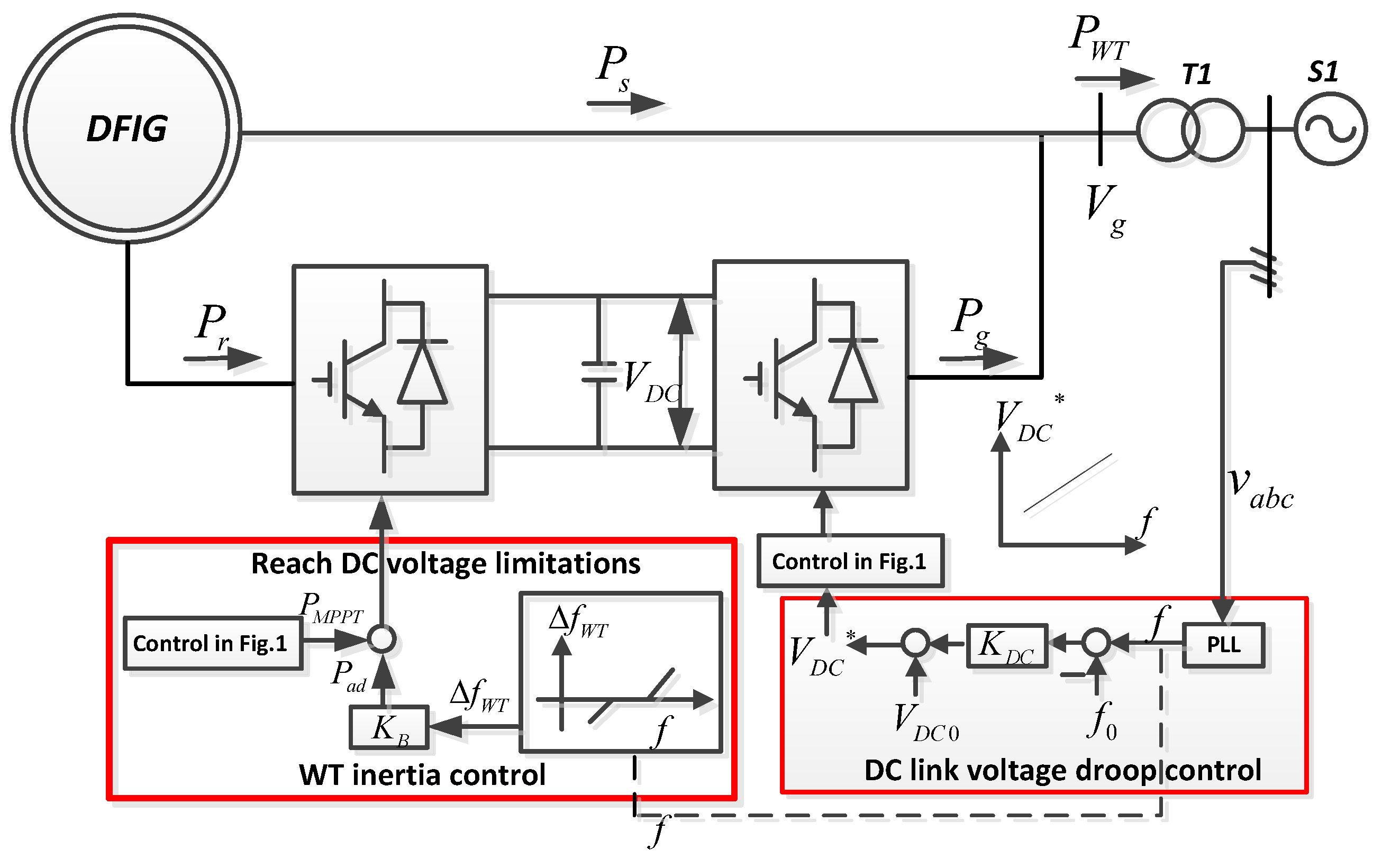
In order better to resolve the contradictory between providing the system frequency support and the maximal wind energy harvesting, a cascading control scheme that sequentially activates the inertia responses from the installed super-capacitor energy and then WT rotational KE automatically is proposed. The core of the scheme is that the energy stored in the super-capacitor is always firstly used, and WT rotational energy is exerted for system support only if there is still frequency deviation. In the proposed control, the stored energy in the super-capacitor is maximally utilized so that less wind energy can be curtailed due to the deviations from the MPPT caused by emulated inertia control. In the following sections, the concrete control design of GSC and RSC of DFIG based WT is illustrated.

4.1. Super-Capacitor Activated Only

In the cascading control, GSC still adopts DC-link voltage droop control. When the system frequency excursion is within a small range, the installed super-capacitor will contribute only to system support, and WT emulated inertia control is not activated, since it has impaired impacts to the MPPT operation of WT once there is activation of WT inertia control. This cascading design logic can better harvest the wind energy compared to the first simultaneous control. It may be economical in the daily operation of the system operator where small system frequency excursion prevails.

4.2. Both Super-Capacitor and WT Rotor KE Activated

The stored electrical energy will use up once the DC-link voltage reaches its limitation when system encounters large frequency deviations. Consequently, the rotational KE is activated to provide system support. To realize the frequency support scheme in Section 3.2, a proper designed control scheme (AC system frequency dead band) is necessary to sequentially utilize the stored electrical energy in the stalled super-capacitor and the rotational KE in the rotor mass of DFIG-based WT. As a result, the frequent utilization of rotational KE of DFIG-based WT is effectively avoided via the above design philosophy:
Δ f WT = { Δ f f                 when   V DC = 0.9   or   V DC = 1.1 0                             when    0.9 < V DC < 1.1 ,
where fWT in (27) is the designed AC frequency deviation, which is an input signal of the emulated inertia control of WT. f′ is the defined cut-off frequency.
The cut-off frequency f′ represents the deviation of the AC system frequency deviation once super-capacitor uses up its energy (DC-link voltage reaches its limitation), yielding as:
f = { 0.1 / K DC                when   V DC = 1.1 0.1 / K DC             when   V DC = 0.9 ,
Apparently, only the installed super-capacitor will be activated for the system support when the AC system frequency deviation is within the defined cut-off system frequency, as in Equation (28). When the system frequency deviation goes larger and exceeds the defined cut-off frequency, the rotational KE of WT will be released out for system support. The cascading control design has two distinguished merits compared to the first simultaneous control scheme: (1). Less wind energy production will be curtailed due to the less frequent activation of the rotor KE for the system support. and (2). The cascading design can optimally utilize the WT’s self-potentials and it is very suitable for the daily system operation when small system disturbances prevail. The defined virtual inertia constant HR provided by the WT rotational KE can be expressed as follows:
H R = H s × ω r 0 × Δ ω r f 0 × Δ f WT ,
The control scheme of the proposed cascading control is shown in Figure 4. The total defined virtual inertia constant HWT by the DFIG-based WT is shown as below:
H WT = { H R                 when   V DC = 0.9   or   V DC = 1.1 H DC               when   0.9 < V DC < 1.1 ,

5. Simulation Studies

The 
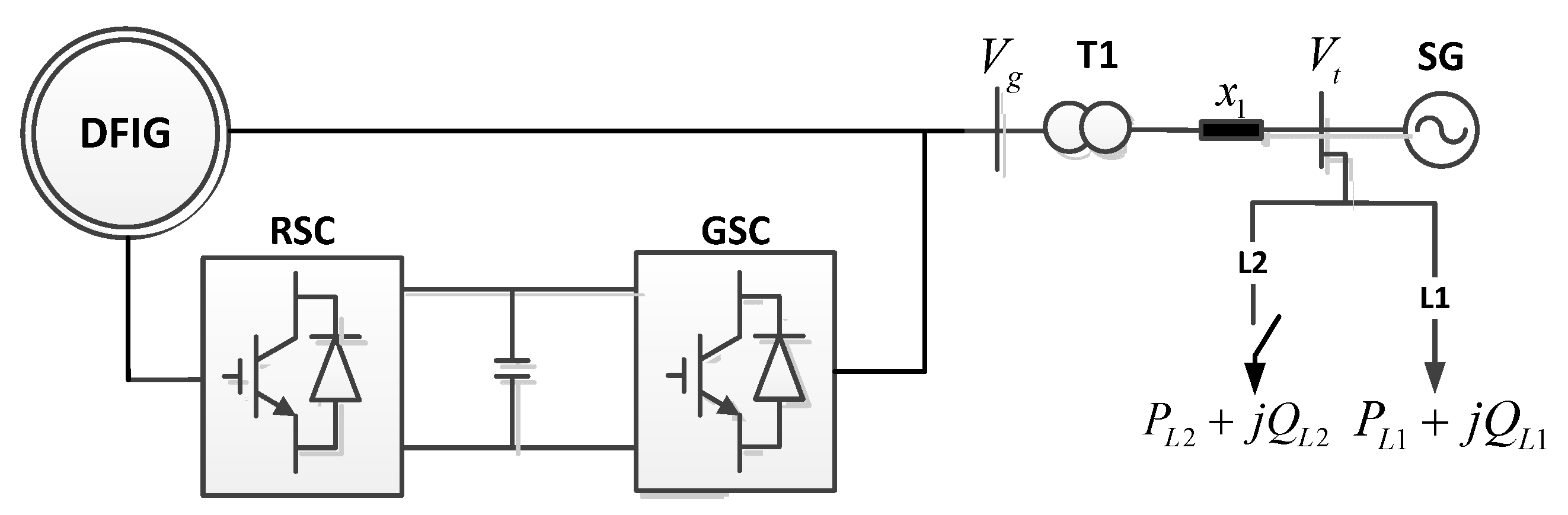
Figure 5 depicts a test model system that contains one SG, two local loads (L1 and L2), and a DFIG-based WT. The power grid is simply represented by the built seventh-order SG model [29] and its detailed parameters are listed in Table 1. The rating of the built SG and the DFIG-based WT is 3 MVA and 2 MVA, respectively. The wind power capacity penetration is around 40% in the designed system. L1 is a fixed load PL1 + QL1 as 3 MW + 0.3 Mvar, and the capacity of the other dump load L2 PL2 + QL2 is set as 0.25 MW + 0.025 Mvar. In the test system, the droop control gain of the primary frequency control of the SG is set to 4%. The rated DC-link voltage of DFIG is set as 1.2 kV. The PWM frequency of the back-to-back converters is 10 kHz. More parameters of the modal system can be referred to the Appendix. The reactance and resistance of the line x1 is 0.025 Ω and 0.001 Ω. The transformer ratio is 0.69 kV/6.6 kV. The equivalent reactance of transformer in primary side is 0.05 p.u. and 0.004 p.u., respectively. The simulation software is DIgSILENT/Powerfactory, and the electro-mechanical simulation method is utilized and the time step is 75 μs.

5.1. Sudden Load Increase with Same Control Parameters

To simulate the sudden load increase disturbance of the system, the dump load PL2 + QL2 is suddenly switched on at t = 10 s. In this case study, the control parameters for the droop control of the GSC (utilizing the energy stored in the super-capacitor) and the droop control for the RSC (utilizing the WT rotational KE) are set as KDC = 2 and KB = −4 in the simultaneous control and the proposed cascading control scheme. Figure 6 shows the simulation results for this case. It is apparently seen that the system frequency deviation with both control scheme is effectively mitigated compared to the no additional frequency support control involved as shown in Figure 6a. In addition, the system frequency nadir by the first control scheme (simultaneous control) is higher than the second control scheme (cascading control). This can be explained that the system support by the cascading control is only from the installed super-capacitor when the DC link-voltage is within its limitation, however, the system support can be obtained from both super-capacitor and the WT rotational KE. Accordingly, this well explains that the absolute rate of change of the frequency (ROCOF) value by the first control is apparently lower than that with the second proposed control, as shown in Figure 6b. From Figure 6c, it is shown that the mechanical power from SG is increased fastest with no additional control involved. However, it increases much more softly with the simultaneous control than that with cascading control, since more system support can be provided via first control. In this case study, DC-link voltage of both control schemes, as shown in Figure 6d, is within its limitations, since a relatively small KDC is selected. Accordingly, the second control does not activate WT rotational KE, as shown in Figure 6f,h. Figure 6f shows that the stator active power suddenly increases when detecting the system disturbance by first control. Correspondingly, the rotor speed of DFIG begins to decrease to release the partially KE to support the system frequency. Partially wind production will be curtailed since the rotor speed of DFIG deviates from its optimal speed. It can be roughly calculated as 0.0969 (shadow area marked in S), and indicates the curtailment the wind energy production during dynamics.

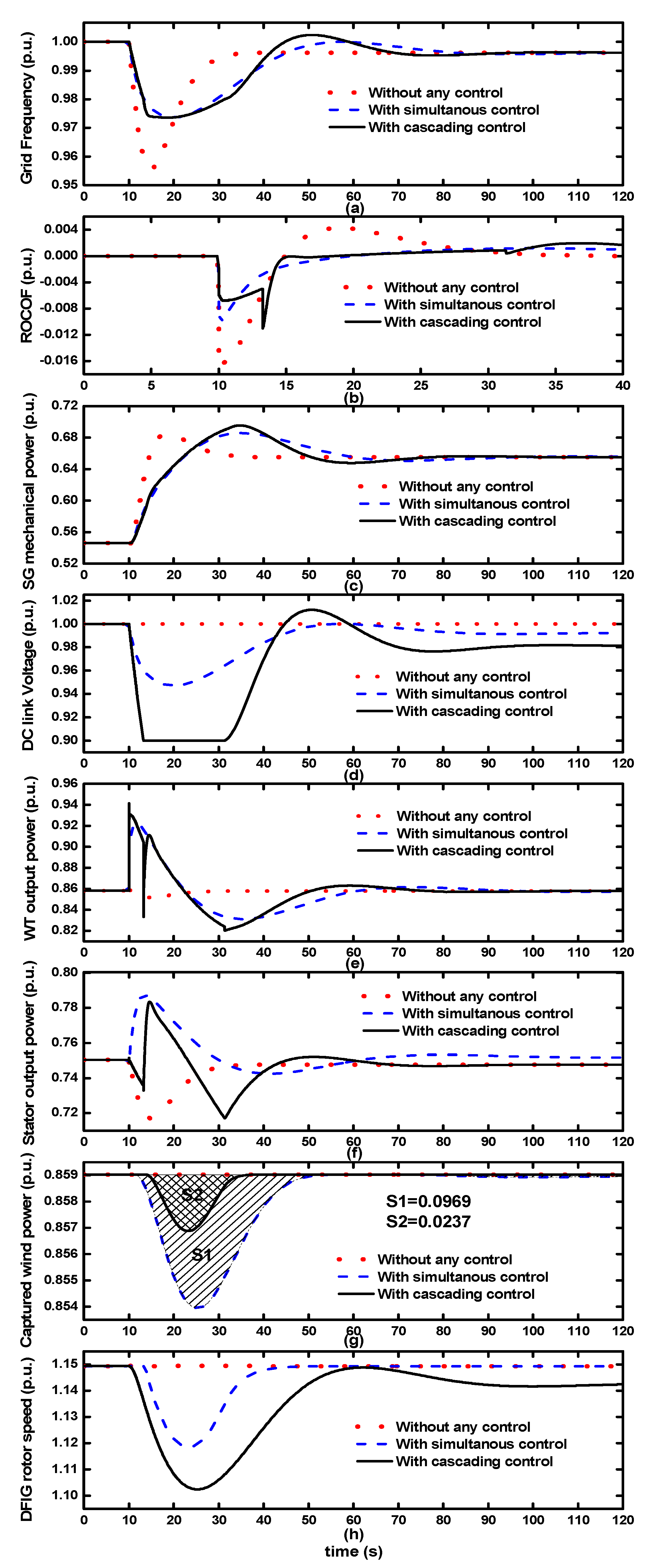
5.2. Sudden Load Increase with Different Control Parameters

Same sudden load increase event as the first case study is implemented, and Figure 7 shows the simulation results. In this case, different control paraments are adopted to better compare two proposed schemes with a relatively fair evaluation index. The droop gain of the DC-link voltage control (utilizing the energy in super-capacitor) KDC is set as 2 and 5 for the both schemes, respectively. The selection criterion of KDC in cascading control is based on the system frequency excursion. In this paper, it is assumed that when the frequency excursion is over ±0.02 p.u., WT rotor KE begin to release out for stabilizing the system frequency. KB of the first scheme (KBI = −4) is the same as the previous case. The KB of second control is selected by achieving the nearly the same frequency nadir or summit as with the first control under the same system disturbances, and it can be proved that both controls can provide the similar frequency support ability for the system. Accordingly, the energy production that can be saved by two controls can be fairly compared while rendering similar supports via two schemes. Accordingly, KB of the second scheme is selected as −10 (KBII = −10). It is shown from Figure 7a,b that the absolute ROCOF value with the simultaneous control in the beginning of the event is larger than that of the second control. This is reasonable since the second control implements a larger droop parameter; thus, it can provide more system support. As shown in Figure 7d, because of the larger KDC in second control, DC-link voltage reaches its limitations faster, and the installed super-capacitor cannot provide any system support and it well explains the profile of DFIG WT active power is unsmoothed in Figure 7e. Sequentially, the rotational KE of DFIG can be released out by the cascading control. The active power from the stator increases during the disturbances due to the releasable partial KE stored in the rotational WT as shown in Figure 7f. It should be clearly noted that in Figure 7g less energy production will be induced by the second control compared to the first one. The wind energy production losses are 0.0969 per unit (marked as S1) and 0.0237 (marked as S2) with both controls, which effectively verifies the energy efficient merit of the second control.

5.3. Sudden Load Decrease with Different Control Parameters

The dump load is suddenly switched out at t = 10 s to simulate the sudden load decrease event, as shown in Figure 8. It is clearly shown that the frequency peaks with both proposed schemes during the system disturbance are significantly lower than that with no additional control involved. To better compare the control impact on the harvested energy by two controls, control parameters of the two schemes are the same as in the previous case. The second control has a quicker DC-link voltage rise in Figure 8d, since the larger KDC is adopted. Notably, the super-capacitor’s electrical energy has been used up once DC-link voltage reaches its limitation and it well explains the unsmoothed profile of active power generation of DFIG in the second control, as shown in Figure 8e. It is apparently seen in Figure 8g,h that the proposed scheme leads to a smaller deviation from the optimal rotor speed. Consequently, the captured wind energy by the second control (S2 = 0.0237) is less than that by the first control (S1 = 0.0855).

6. Conclusions

Two novel control schemes for DFIG-based WT to render fast system inertia support are proposed. The first control (simultaneous control) aims to utilize the installed super-capacitor energy and rotational KE of WT simultaneously for system support. In contrast, the second proposed control can exert the super-capacitor energy first and WT rotational KE can only be utilized when large system frequency deviation still exists. The case studies of two proposed controls show that both controls can provide similar performance in stabilizing system frequency given the same frequency deviation. Particularly, the second cascading control distinguishes itself by minimizing the control impacts on energy harvesting, and more wind energy can be captured during dynamics.

Acknowledgments

The work was supported by the National Natural Science Foundation of China (Grant No. 51707091), the Scientific Research Foundation for the High-level Personnel of Nanjing Institute of Technology (Grant No. YKJ201613), the Operation Fund of Guangdong Key Laboratory of Clean Energy Technology (Grant No. 2014B030301022) and the Open Research Fund of Jiangsu Collaborative Innovation Center for Smart Distribution Network, Nanjing Institute of Technology (Grant No. XTCX201711).

Author Contributions

All the authors conceived and designed the study. Liansong Xiong, Yujun Li and Zhirong Xu performed the simulation and wrote the manuscript with guidance from Yixin Zhu and Ping Yang.

Conflicts of Interest

The authors declare no conflict of interest.

Appendix A

The parameters of studied DFIG-based WT are as follows:
WT: cut in wind speed: 4 m/s; lower limit of the wind speed: 7 m/s; rated wind speed: 14 m/s; inertia constant: Hs = 4.5 s; and time constant of the pitch serve: Tβ = 0.25 s.
DFIG: rated power: 2 MW; rated voltage: 690 V; rated rotor speed: 1.23 p.u.; stator resistance: Ra = 50 μΩ; d axis inductance: Ld = 5.5 mH; and q axis inductance: Lq = 3.75 mH.
Converters: resistance of grid side inductor: RL = 0.003 p.u.; inductance of grid side inductor: L = 0.3 p.u.; DC-link capacitor: CDC = 60 mF; super-capacitor: CS = 3 F; and rated DC-link voltage: VDCn = 1.2 kV.

References

  1. Ghosh, S.; Kamalasadan, S.; Senroy, N.; Enslin, J. Doubly Fed Induction Generator (DFIG)-Based Wind Farm Control Framework for Primary Frequency and Inertial Response Application. IEEE Trans. Power Syst. 2015, 30, 1861–1871. [Google Scholar] [CrossRef]
  2. Morren, J.; de Haan, S.W.H.; Kling, W.L.; Ferreira, J.A. Wind turbines emulating inertia and supporting primary frequency control. IEEE Trans. Power Syst. 2006, 21, 433–434. [Google Scholar] [CrossRef]
  3. Ye, H.; Pei, W.; Qi, Z. Analytical Modeling of Inertial and Droop Responses from a Wind Farm for Short-Term Frequency Regulation in Power Systems. IEEE Trans. Power Syst. 2015, 30, 3414–3423. [Google Scholar] [CrossRef]
  4. Yang, L.H.; Xu, Z.; Ostergaard, J.; Dong, Z.Y.; Wong, K.P. Advanced Control Strategy of DFIG Wind Turbines for Power System Fault Ride Through. IEEE Trans. Power Syst. 2012, 27, 713–722. [Google Scholar] [CrossRef] [Green Version]
  5. Ekanayake, J.; Jenkins, N. Comparison of the response of doubly fed and fixed-speed induction generator wind turbines to changes in network frequency. IEEE Trans. Energy Convers. 2004, 19, 800–802. [Google Scholar] [CrossRef]
  6. Ramtharan, G.; Ekanayake, J.B.; Jenkins, N. Frequency support from doubly fed induction generator wind turbines. IET Renew. Power Gener. 2007, 1, 3–9. [Google Scholar] [CrossRef]
  7. Conroy, J.F.; Watson, R. Frequency response capability of full converter wind turbine generators in comparison to conventional generation. IEEE Trans. Power Syst. 2008, 23, 649–656. [Google Scholar] [CrossRef]
  8. Leonhard, W.; Grobe, E.M. Sustainable electrical energy supply with wind and pumped storage—A realistic long-term strategy or utopia. In Proceedings of the IEEE Power Engineering Society General Meeting, Denver, CO, USA, 6–10 June 2004; Volume 2, pp. 1221–1225. [Google Scholar]
  9. Daneshi, A.; Khederzadeh, M.; Sadrmomtazi, N.; Olamaei, J. Integration of wind power and energy storage in SCUC problem. In Proceedings of the World Non-Grid-Connected Wind Power and Energy Conference (WNWEC), Nanjing, China, 5–7 November 2010; pp. 1–8. [Google Scholar]
  10. Qu, L.; Qiao, W. Constant power control of DFIG wind turbines with supercapacitor energy storage. IEEE Trans. Ind. Appl. 2011, 47, 359–367. [Google Scholar] [CrossRef]
  11. Wang, S.; Hu, J.B.; Yuan, X.M.; Sun, L. On Inertial Dynamics of Virtual-Synchronous-Controlled DFIG-Based Wind Turbines. IEEE Trans. Energy Convers. 2015, 30, 1691–1702. [Google Scholar] [CrossRef]
  12. Kamel, R.M.; Chaouachi, A.; Nagasaka, K. Three Control Strategies to Improve the Microgrid Transient Dynamic Response during Isolated Mode: A Comparative Study. IEEE Trans. Ind. Electron. 2013, 60, 1314–1322. [Google Scholar] [CrossRef]
  13. Li, Y.; Xu, Z.; Ostergaard, J.; Hill, D.J. Coordinated Control Strategies for Offshore Wind Farm Integration via VSC-HVDC for System Frequency Support. IEEE Trans. Energy Convers. 2017, 32, 843–856. [Google Scholar] [CrossRef]
  14. Li, Y.; Xu, Z.; Meng, K. Optimal Power Sharing Control of Wind Turbines. IEEE Trans. Power Syst. 2017, 32, 824–825. [Google Scholar] [CrossRef]
  15. Li, Y.; Xu, Z.; Wong, K.P. Advanced Control Strategies of PMSG-Based Wind Turbines for System Inertia Support. IEEE Trans. Power Syst. 2017, 32, 3027–3037. [Google Scholar] [CrossRef]
  16. Xue, Y.C.; Tai, N.L. Review of contribution to frequency control through variable speed wind turbine. Renew. Energy 2011, 36, 1671–1677. [Google Scholar]
  17. Vyver, J.V.d.; Kooning, J.D.M.D.; Meersman, B.; Vandevelde, L.; Vandoorn, T.L. Droop Control as an Alternative Inertial Response Strategy for the Synthetic Inertia on Wind Turbines. IEEE Trans. Power Syst. 2016, 31, 1129–1138. [Google Scholar] [CrossRef]
  18. Lalor, G.; Mullane, A.; O’Malley, M. Frequency control and wind turbine technologies. IEEE Trans. Power Syst. 2005, 20, 1905–1913. [Google Scholar] [CrossRef]
  19. Wang, Y.; Meng, J.; Zhang, X.; Xu, L. Control of PMSG-Based Wind Turbines for System Inertial Response and Power Oscillation Damping. IEEE Trans. Sustain. Energy 2015, 6, 565–574. [Google Scholar] [CrossRef] [Green Version]
  20. Kayikci, M.; Milanovic, J.V. Dynamic Contribution of DFIG-Based Wind Plants to System Frequency Disturbances. IEEE Trans. Power Syst. 2009, 24, 859–867. [Google Scholar] [CrossRef]
  21. Chang-Chien, L.-R.; Lin, W.-T.; Yin, Y.-C. Enhancing Frequency Response Control by DFIGs in the High Wind Penetrated Power Systems. IEEE Trans. Power Syst. 2011, 26, 710–718. [Google Scholar] [CrossRef]
  22. De Almeida, R.G.; Lopes, J.A.P. Participation of doubly fed induction wind generators in system frequency regulation. IEEE Trans. Power Syst. 2007, 22, 944–950. [Google Scholar] [CrossRef]
  23. Uehara, A.; Pratap, A.; Goya, T.; Senjyu, T.; Yona, A.; Urasaki, N. A Coordinated Control Method to Smooth Wind Power Fluctuations of a PMSG-Based WECS. IEEE Trans. Energy Convers. 2011, 26, 550–558. [Google Scholar] [CrossRef]
  24. Arani, M.F.M.; El-Saadany, E.F. Implementing Virtual Inertia in DFIG-Based Wind Power Generation. IEEE Trans. Power Syst. 2013, 28, 1373–1384. [Google Scholar] [CrossRef]
  25. Hansen, A.D.; Iov, F.; Sørensen, P.; Cutululis, N.; Jauch, C.; Blaabjerg, F. Dynamic Wind Turbine Models in Power System Simulation Tool DIgSILENT, 2nd ed.; Project Report Risø-R-1400 (EN); Risø National Laboratory, Technical University of Denmark: Copenhagen, Denmark, 2003. [Google Scholar]
  26. Wu, F.; Zhang, X.P.; Godfrey, K.; Ju, P. Small signal stability analysis and optimal control of a wind turbine with doubly fed induction generator. IET Gener. Transm. Distrib. 2007, 5, 751–760. [Google Scholar] [CrossRef]
  27. Xiong, L.S.; Zhuo, F.; Wang, F.; Liu, X.K.; Chen, Y.; Zhu, M.H.; Yi, H. Static synchronous generator model: A new perspective to investigate dynamic characteristics and stability issues of grid-tied PWM inverter. IEEE Trans. Power Electron. 2016, 31, 6264–6280. [Google Scholar] [CrossRef]
  28. Padron, J.F.M.; Lorenzo, A.E.F. Calculating Steady-State Operating Conditions for Doubly-Fed Induction Generator Wind Turbines. IEEE Trans. Power Syst. 2010, 25, 922–928. [Google Scholar] [CrossRef]
  29. Anderson, P.; Fouad, A.A. Power System Control and Stability; Iowa State University Press: Ames, IA, USA, 1977. [Google Scholar]
Figure 1. Control diagram of a doubly fed induction generator (DFIG)-based wind turbine (WT).
Energies 11 00103 g001
Figure 2. WT operation characteristic.
Energies 11 00103 g002
Figure 3. Control scheme of the simultaneous control.
Energies 11 00103 g003
Figure 4. Control scheme of the cascading control.
Energies 11 00103 g004
Figure 5. The outline of the model system.
Energies 11 00103 g005
Figure 6. Results for sudden load increase with same control parameters: (a) the grid frequency; (b) ROCOF; (c) the mechanical power from SG; (d) the DC link-voltage; (e) the output power from WT; (f) the output power from stator; (g) the captured wind power; (h) the rotor speed of DFIG.
Energies 11 00103 g006
Figure 7. Results for sudden load increase with different control parameters: (a) the grid frequency; (b) ROCOF; (c) the mechanical power from SG; (d) the DC link-voltage; (e) the output power from WT; (f) the output power from stator; (g) the captured wind power; (h) the rotor speed of DFIG.
Energies 11 00103 g007
Figure 8. Results for sudden load decrease with different control parameters. (a) the grid frequency; (b) ROCOF; (c) the mechanical power from SG; (d) the DC link-voltage; (e) the output power from WT; (f) the output power from stator; (g) the captured wind power; (h) the rotor speed of DFIG
Energies 11 00103 g008
Table 1. Parameters for the synchronous generator (SG).
SymbolItemValue
UgTerminal Voltage6.6 kV
HgInertia Time constant4 s
xd, xd′, xdd-axis synchronous reactance2.642, 0.377, 0.21
xq, xq″, xlq-axis synchronous reactance2.346, 0.18, 0.18
Td′, Td″, TqSG Time constant0.635, 0.015, 0.015
RPTurbine permanent droop0.04
TRGovernor time constant 8.405 s
TservoServo-motor time constant0.5 s
KgainExciter regulator gain400
TeExciter time constant0.01 s

