Influence of Spatial Relationships between Key Strata on the Height of Mining-Induced Fracture Zone: A Case Study of Thick Coal Seam Mining

Abstract
:1. Introduction
2. Development of Fractures in Overburden Induced by Thick Seam Mining
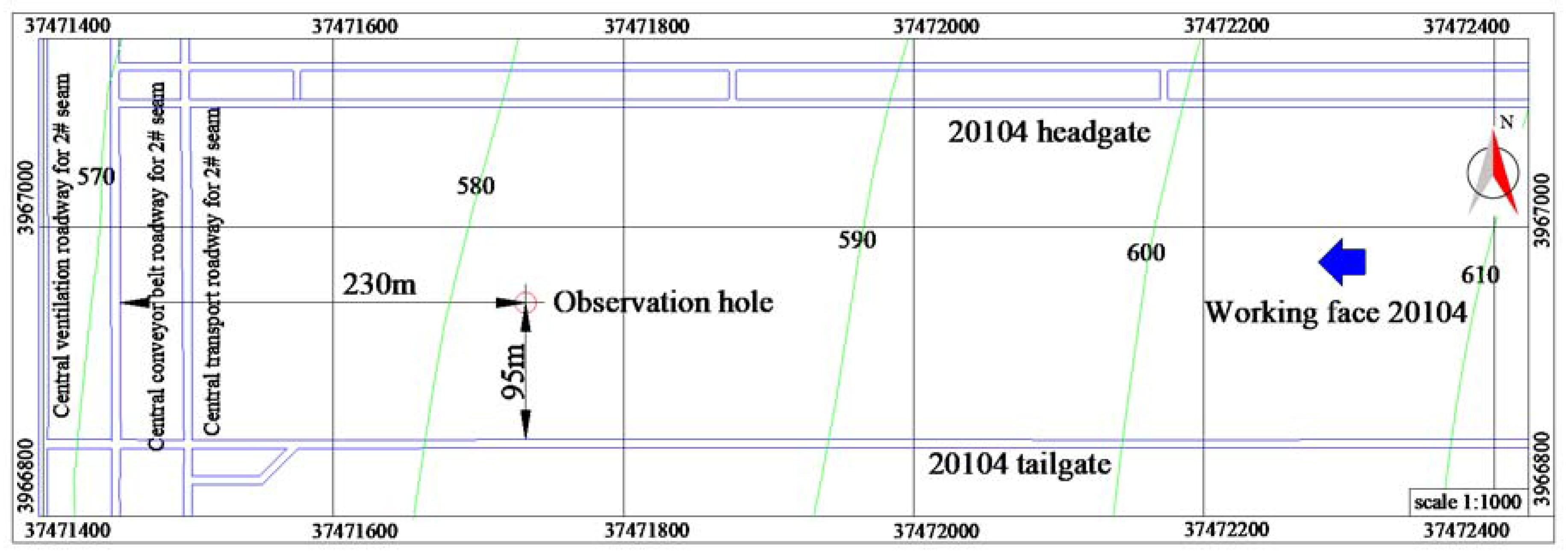
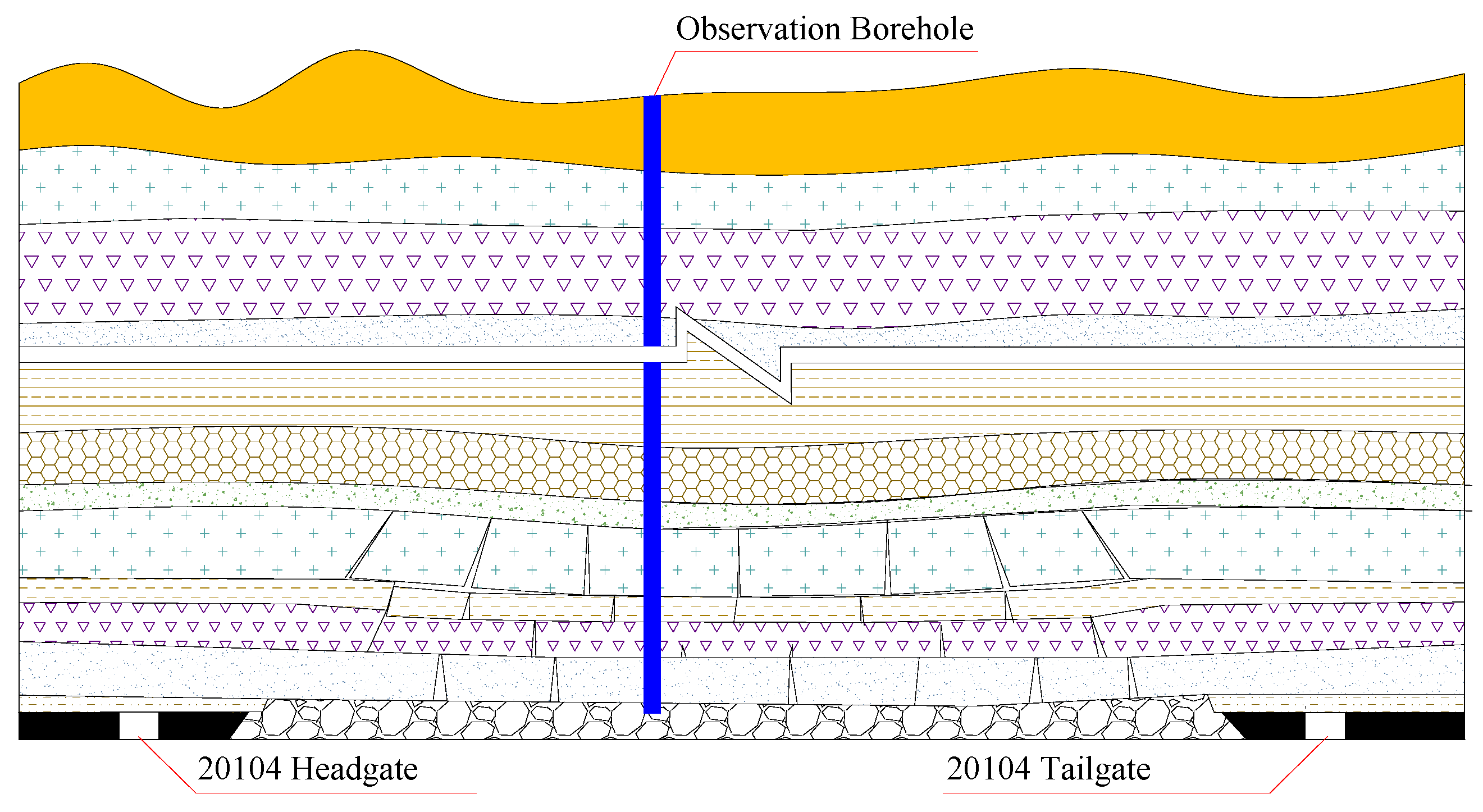
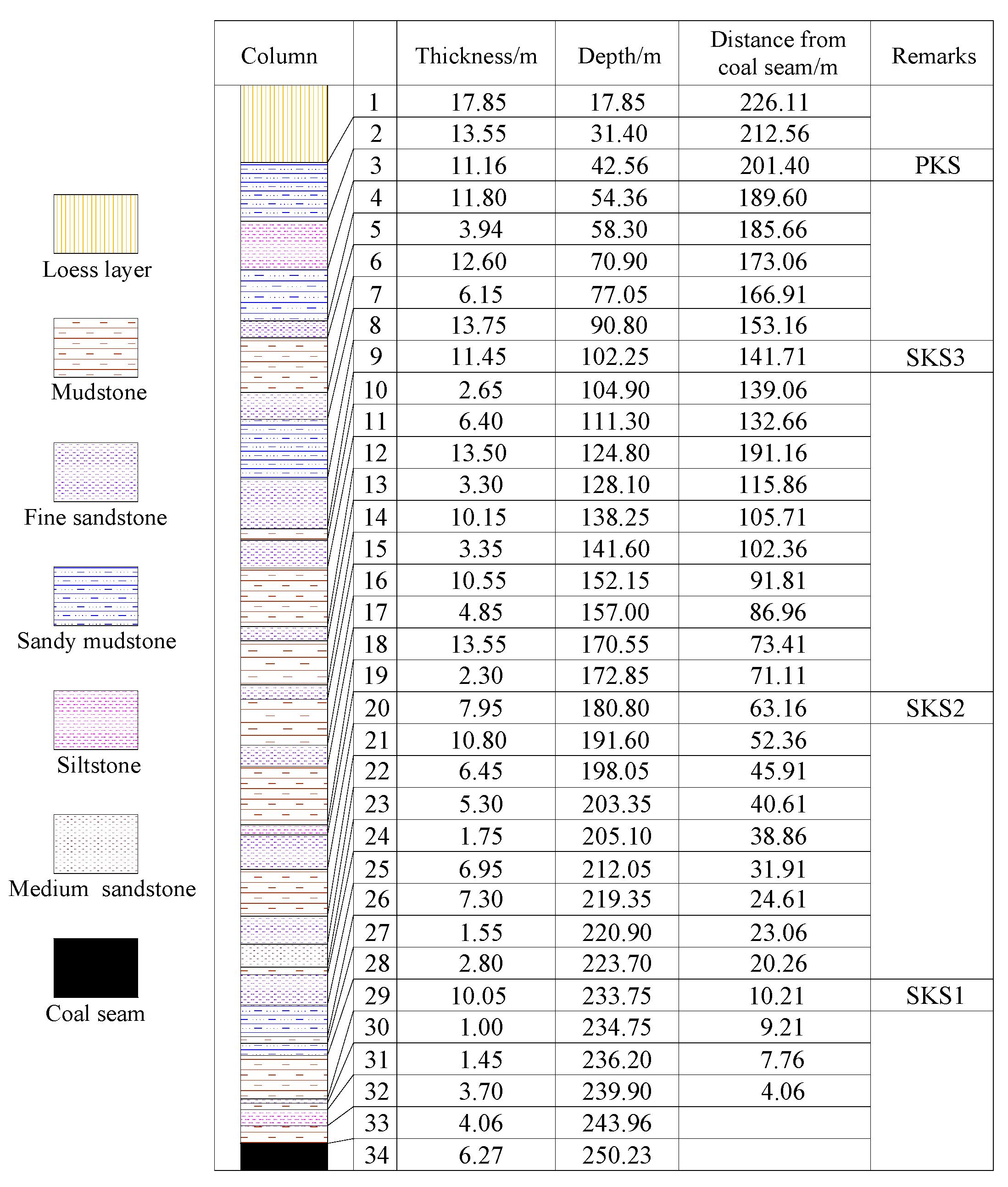
2.1. Geological Conditions
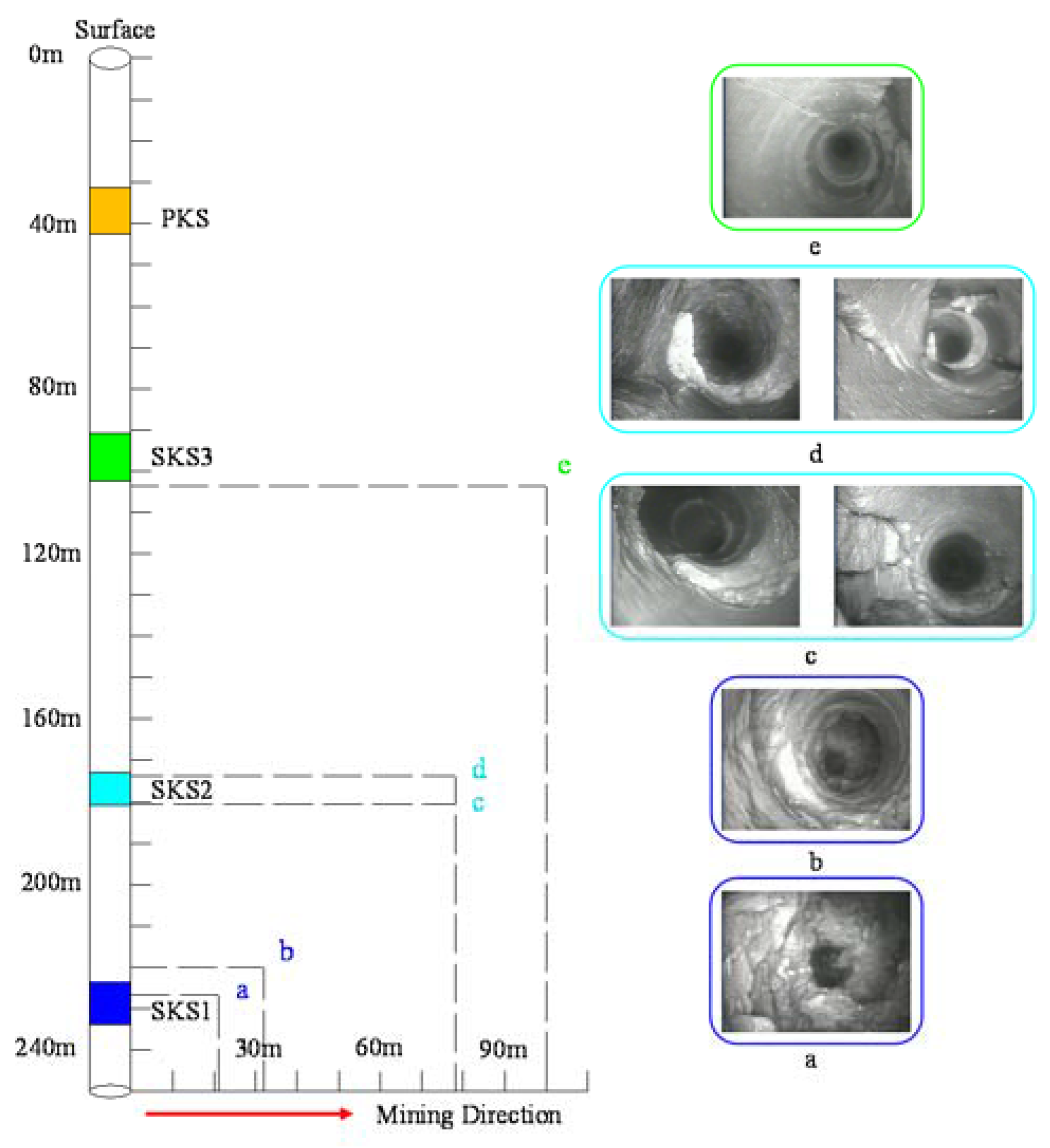
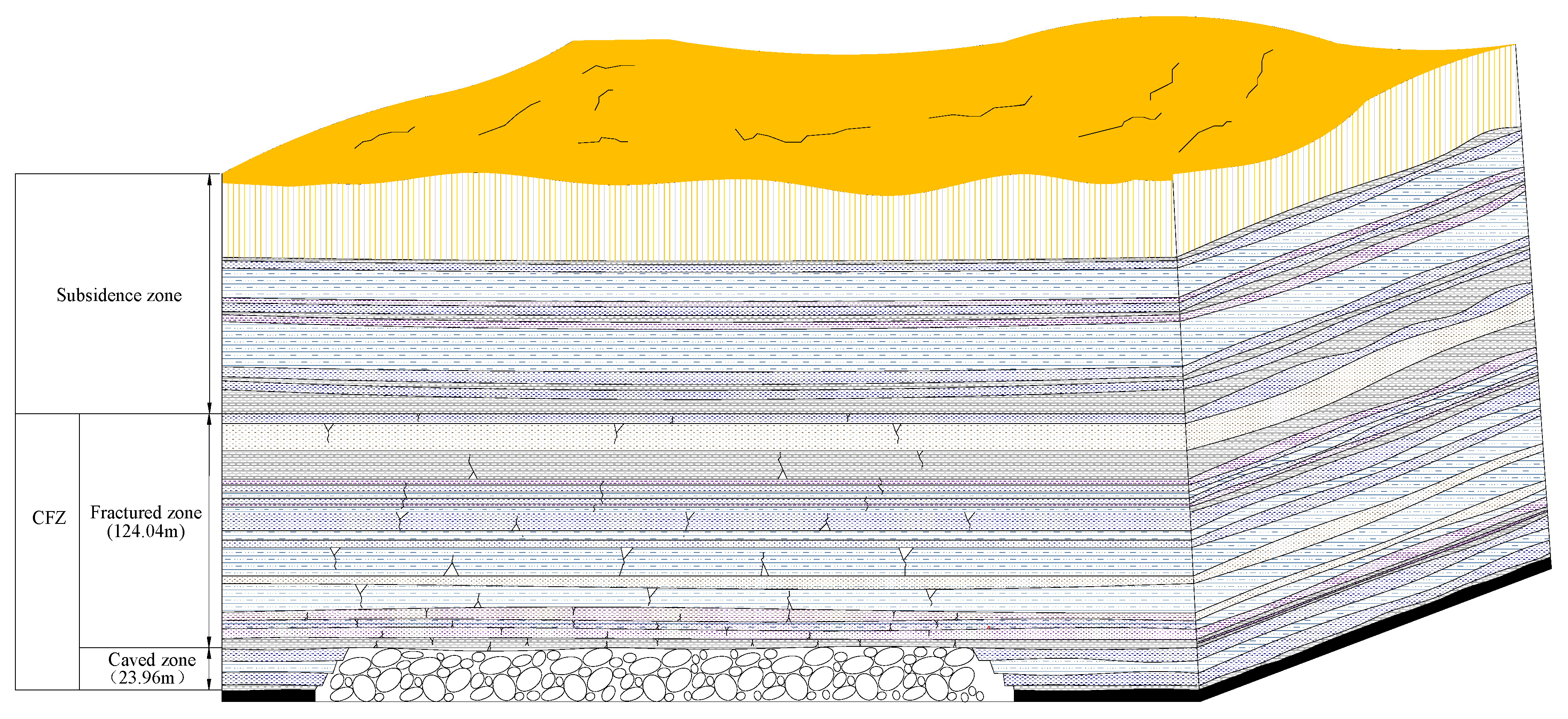
2.2. Field Measurements of the Height of CFZ
3. The Mechanism by Which the KS Influenced the CFZ’s Height
3.1. Influence of KS on the CFZ’s Height
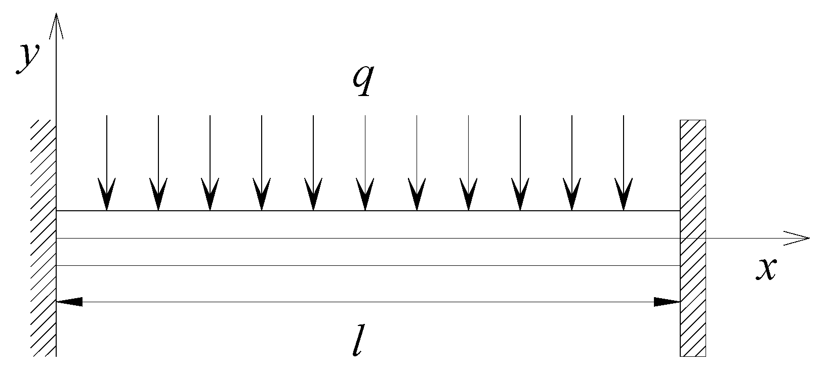
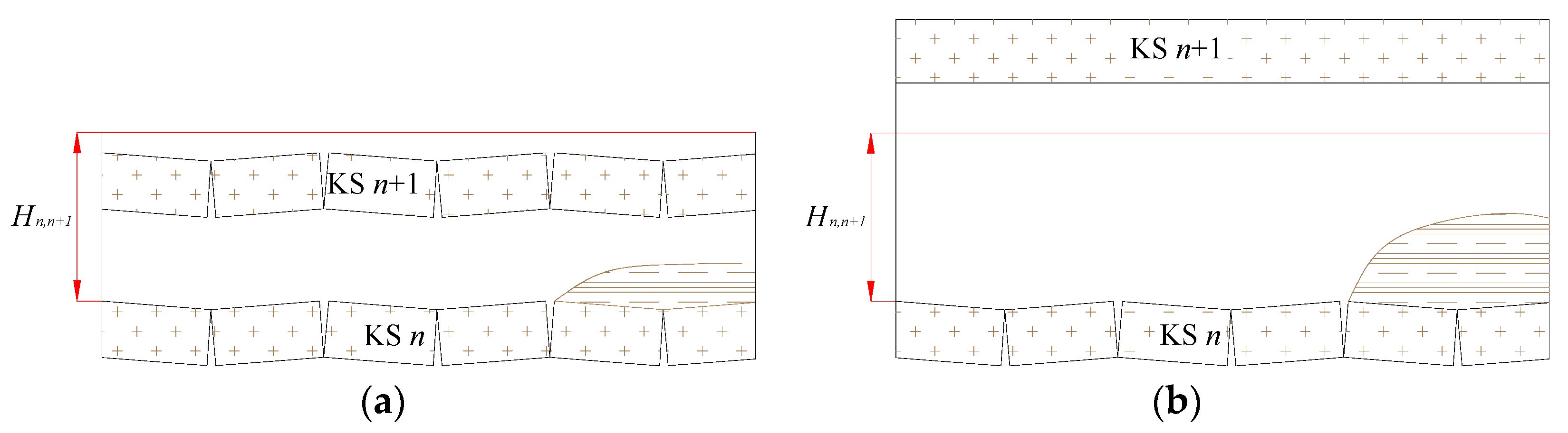
3.2. Spatial Relationships between KS Required for Their Fracturing
4. Discussion
5. Conclusions
Acknowledgments
Author Contributions
Conflicts of Interest
Abbreviations
| CFZ | Conductive Fracture Zone |
| KS | Key Strata |
| HoL | Height of Linkage |
| PKS | Primary Key Stratum |
| SKS | Secondary Key Strata |
References
- Wang, W.X.; Sui, W.H.; Faybishenko, B.; Stringfellow, W.T. Permeability variations within mining-induced fractured rockmass and its influence on groundwater inrush. Environ. Earth Sci. 2016, 75, 326. [Google Scholar] [CrossRef]
- Wang, S.F.; Li, X.B.; Wang, D.M. Mining-induced void distribution and application in the hydro-thermal investigation and control of an underground coal fire: A case study. Process Saf. Environ. Prot. 2016, 102, 734–756. [Google Scholar] [CrossRef]
- Qu, Q.D.; Xu, J.L.; Wu, R.L.; Qin, W.; Hu, G.Z. Three-zone characterisation of coupled strata and gas behaviour in multi-seam mining. Int. J. Rock Mech. Min. Sci. 2015, 78, 91–98. [Google Scholar] [CrossRef]
- Qiao, W.; Li, W.P.; Li, T.; Chang, J.Y.; Wang, Q.Q. Effects of coal mining on shallow water resources in semiarid regions: A case study in the Shennan mining area, Shaanxi, China. Mine Water Environ. 2017, 36, 104–113. [Google Scholar] [CrossRef]
- Zhang, D.S.; Fan, G.W.; Liu, Y.D.; Ma, L.Q. Field trials of aquifer protection in longwall mining of shallow coal seams in China. Int. J. Rock Mech. Min. Sci. 2010, 47, 908–914. [Google Scholar] [CrossRef]
- Zhang, D.S.; Fan, G.W.; Ma, L.Q.; Wang, X.F. Aquifer protection during longwall mining of shallow coal seams: A case study in the Shendong Coalfield of China. Int. J. Coal Geol. 2011, 86, 190–196. [Google Scholar] [CrossRef]
- Ju, J.F.; Xu, J.L. Surface stepped subsidence related to top-coal caving longwall mining of extremely thick coalseam under shallow cover. Int. J. Rock Mech. Min. Sci. 2015, 78, 27–35. [Google Scholar]
- Shi, L.; Liu, Y.F.; Wang, S.D. Overburden failure height and fissure evolution characteristics of deep buried, extra thick coal seam and fully-mechanized caving mining of China. In Proceedings of the 2015 International Conference on Water Resources and Environment, Beijing, China, 25–28 July 2015; pp. 207–216. [Google Scholar]
- Wang, F.T.; TU, S.H.; Zhang, C.; Zhang, Y.W. Evolution mechanism of water-flowing zones and control technology for longwall mining in shallow coal seams beneath gully topography. Environ. Earth Sci. 2016, 75, 1309. [Google Scholar] [CrossRef]
- Wang, X.F.; Zhang, D.S.; Zhang, C.G.; Fan, G.W. Mechanism of Mining-induced Slope Movement for Gullies Overlaying Shallow Coal Seams. J. Mt. Sci. 2013, 10, 388–397. [Google Scholar] [CrossRef]
- Zhang, J.; Jiang, H.; Deng, X.; Ju, F. Prediction of the height of the water-conducting zone above the mined panel in solid backfill mining. Mine Water Environ. 2014, 33, 317–326. [Google Scholar] [CrossRef]
- Palchik, V. Influence of physical characteristics of weak rock mass on height of caved zone over abandoned subsurface coal mines. Environ. Geol. 2002, 42, 92–101. [Google Scholar] [CrossRef]
- Palchik, V. Formation of fractured zones in overburden due to longwall mining. Environ. Geol. 2003, 44, 28–38. [Google Scholar]
- Palchik, V. Bulking factors and extents of caved zones in weathered overburden of shallow abandoned underground workings. Int. J. Mech. Min. Sci. 2015, 79, 227–240. [Google Scholar] [CrossRef]
- Cheng, G.W.; Ma, T.H.; Tang, C.; Liu, H.Y.; Wang, S.J. Zoning model for coal mining-induced strata movement based on microseismic monitoring. Int. J. Rock Mech. Min. Sci. 2017, 94, 123–138. [Google Scholar] [CrossRef]
- Xiong, Z.Q.; Wang, C.; Zhang, N.C. A Field Investigation for overlying strata behaviour study during protective seam longwall overmining. Arab. J. Geosci. 2015, 8, 7797–7809. [Google Scholar] [CrossRef]
- Wang, H.Z.; Zhang, D.S.; Wang, X.F.; Zhang, W. Visual exploration of the spatiotemporal evolution law of overburden failure and mining-induced fractures: A case study of the Wangjialing coal mine in China. Minerals 2017, 7, 35. [Google Scholar] [CrossRef]
- Niedbalski, Z.; Malkowski, P.; Majcherczyk, T. Monitoring of stand-and-roof-bolting support: Desing optimization. Acta Geodyn. Geomater. 2013, 10, 215–226. [Google Scholar] [CrossRef]
- Malkowski, P. The impact of the physical model selection and rock mass stratification on the results of numerical calculations of the state of rock mass deformation around the roadways. Tunn. Undergr. Space Technol. 2015, 50, 365–375. [Google Scholar] [CrossRef]
- Majcherczyk, T.; Malkowski, P.; Niedbalski, Z. Describing quality of rocks around underground headings: Endoscopic observations of fractures. In Proceedings of the International Symposium of the International-Society-for-Rock-Mechanics, Brno, Czech Republic, 18 May–20 August 2005; pp. 355–360. [Google Scholar]
- Zhang, W.; Zhang, D.S.; Ma, L.Q. Dynamic evolution characteristics of mining-induced fractures in overlying strata detected by radon. Nuclear Sci. Tech. 2011, 22, 334–337. [Google Scholar]
- Zhang, W.; Zhang, D.S.; Wu, L.X.; Wang, H.Z. On-site radon detection of mining-induced fractures from overlying strata to the surface: A case study of the Baoshan coal mine in China. Energies 2014, 7, 8483–8507. [Google Scholar] [CrossRef]
- Xu, J.L.; Wang, X.Z.; Liu, W.T.; Wang, Z.G. Effects of primary key stratum location on height of water flowing fracture zone. Chin. J. Rock Mech. Eng. 2009, 28, 380–385. (In Chinese) [Google Scholar]
- Miao, X.X.; Cui, X.M.; Wang, J.A.; Xu, J.L. The height of fractured water-conducting zone in undermined rock strata. Eng. Geol. 2011, 120, 32–39. [Google Scholar] [CrossRef]
- Xu, J.L.; Qian, M.G. Method to distinguish key strata in overburden. J. China Univ. Min. Technol. 2000, 29, 463–467. [Google Scholar]
- Ju, J.L.; Xu, J.L.; Xu, J.M. A case study of surface borehole wall dislocation induced by top-coal longwall mining. Energies 2017, 10, 2100. [Google Scholar] [CrossRef]
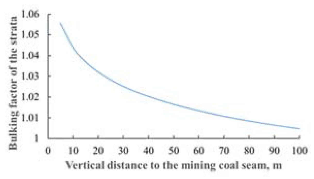
- Shao, H.; Jiang, S.G.; Wang, L.Y.; Wu, Z.Y. Bulking factor of the strata overlying the gob and a three-dimensional numerical simulation of the air leakage flow field. Min. Sci. Technol. 2011, 21, 261–266. [Google Scholar]

| KS No. | Rock Type | Thickness (m) | Tensile Strength (MPa) | Elastic Modulus (GPa) | Wmax (mm) |
|---|---|---|---|---|---|
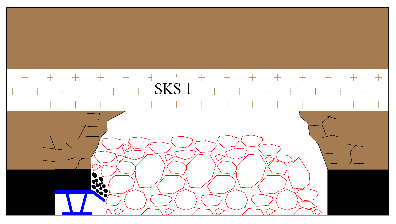
| SKS 1 | Mudstone | 10.05 | 2.2 | 17.0 | 5.9 |
| SKS 2 | Fine sandstone | 7.95 | 6.0 | 45.6 | 2.6 |
| SKS 3 | Fine sandstone | 11.45 | 6.0 | 45.6 | 3.1 |
| PKS | Siltstone | 11.16 | 5.2 | 40.0 | 1.4 |
| Model Type | Model a | Model b | Model c | Model d |
|---|---|---|---|---|
| Illustration | 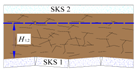 | 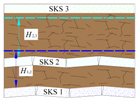 | 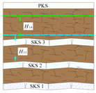 | 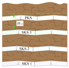 |
| Spatial relationships between adjacent KS | The height difference between SKS 2 and SKS 1 is greater than the HoL between them. | The height difference between SKS 2 and SKS 1 is smaller than the HoL between them, while the height difference between SKS 3 and SKS 2 is greater than the corresponding HoL. | The height difference between SKS 3 and SKS 2 is smaller than the HoL between them, while the height difference between PKS and SKS 3 exceeds the corresponding HoL. | The height difference between PKS and SKS 3 is less than the HoL between them. |
| State of KS | SKS 2 is unfractured. | SKS 2 is fractured while SKS 3 is unfractured | SKS 3 is fractured while PKS is unfractured | PKS is fractured |
| The height of CFZ | Fractures terminate at the bottom of SKS 2. | Fractures propagate through SKS 2 and terminate at the bottom of SKS 3. | Fractures run through SKS 3 and terminate at the bottom of PKS. | Fractures extend through all key strata and reach the surface |
| Adjacent KS | Height Difference between Them (m) | HoL between Them (m) |
|---|---|---|
| SKS 1–SKS 2 | 52.95 | 61.25 |
| SKS 2–SKS 3 | 78.55 | 59.32 |
© 2018 by the authors. Licensee MDPI, Basel, Switzerland. This article is an open access article distributed under the terms and conditions of the Creative Commons Attribution (CC BY) license (http://creativecommons.org/licenses/by/4.0/).
Share and Cite
Li, P.; Wang, X.; Cao, W.; Zhang, D.; Qin, D.; Wang, H. Influence of Spatial Relationships between Key Strata on the Height of Mining-Induced Fracture Zone: A Case Study of Thick Coal Seam Mining. Energies 2018, 11, 102. https://doi.org/10.3390/en11010102
Li P, Wang X, Cao W, Zhang D, Qin D, Wang H. Influence of Spatial Relationships between Key Strata on the Height of Mining-Induced Fracture Zone: A Case Study of Thick Coal Seam Mining. Energies. 2018; 11(1):102. https://doi.org/10.3390/en11010102
Chicago/Turabian StyleLi, Peng, Xufeng Wang, Wenhao Cao, Dongsheng Zhang, Dongdong Qin, and Hongzhi Wang. 2018. "Influence of Spatial Relationships between Key Strata on the Height of Mining-Induced Fracture Zone: A Case Study of Thick Coal Seam Mining" Energies 11, no. 1: 102. https://doi.org/10.3390/en11010102