Article

Circuit Breaker Rate-of-Rise Recovery Voltage in Ultra-High Voltage Lines with Hybrid Reactive Power Compensation

1
School of Electrical Engineering, Shandong University, Jinan 250061, China
2
Rizhao Power Supply Company of State Grid Shandong Electric Power Company, Rizhao 276826, China
*
Author to whom correspondence should be addressed.
Energies 2018, 11(1), 100; https://doi.org/10.3390/en11010100
Submission received: 18 November 2017 / Revised: 15 December 2017 / Accepted: 27 December 2017 / Published: 2 January 2018
(This article belongs to the Section F: Electrical Engineering)

Abstract

:
With the development of ultra-high voltage (UHV) technology, hybrid reactive power compensation (HRPC) will be widely applied in the future. To study the mechanism by which HRPC influences the characteristics of circuit breakers in UHV transmission lines, this paper establishes an improved electromagnetic coupling transmission line model for out-of-phase and short-line faults. Based on the HRPC equivalent model, a simulation analysis was performed on the characteristics of the circuit breaker when a fault occurs. Using an equivalent lumped parameter circuit, the rate-of-rise of recovery voltage (RRRV) computational formula was deduced and computed. The RRRV variation in the circuit breakers in the system, with and without HRPC, was obtained. Given the circuit breaker interruption characteristics, the research results provide an analysis foundation and a theoretical basis for optimizing the HRPC parameters and selecting the arrangements of circuit breakers in an UHV transmission line.

1. Introduction

As long-distance, large-capacity, and low-loss power transmission lines are important for optimizing resources distribution, ultra-high voltage (UHV) transmission technology has become the development focus of the power industry [1,2]. An UHV network enables the interconnection of regional power networks and the optimal distribution of resources in a wider area. The transmission power is significantly improved and the reactive power changes frequently, so the safety and stability of the system is facing both opportunities and challenges [3]. Hybrid reactive power compensation (HRPC) with series compensation and a stepped controlled shunt reactor is an ideal solution to the challenges, as it addresses both the increase in transmission power and the frequent adjustment of reactive power. In recent years, among the switching electrical equipment, as the core of GIS (gas insulated switchgear), the circuit breaker has taken the responsibilities of closing under normal conditions, interrupting load current, short circuit current, out-of-phase current, and so on. Since both the inductance and the capacitance are energy storage components in power systems, a transient process occurs when the operation states change due to normal operations or faults handling. During the state transition, operating overvoltage several times higher than the rated power voltage may occur [3,4,5]. This situation threatens the system insulation and destroys the insulation performance of the system in severe cases, so accidents may occur. After the installation of HRPC in UHV transmission systems, the parameters of the circuits change, and the system oscillation frequency is directly influenced by the energy storage components. Furthermore, the operating overvoltage of circuit breakers is also affected during the interrupting process [6,7,8].
Parameters such as power frequency overvoltage, power frequency resonance overvoltage, secondary arc current, and switching overvoltage have been calculated and analyzed with the use of an EMTP program, for a 500 kV system with high voltage shunt compensation [9]. Load power and power grid requirements have been considered [10], and the fault overvoltage of a 400 kV European network with reactive compensation has been simulated. The fast cut back led to severe overvoltage. The influence of line length and the HRPC compensation degree on the maximum transmission power have been analyzed [11]. The interrupting process of an 1100-kV circuit breaker at an out-of-phase fault with parallel resistance has been studied, and it was shown that the interrupting condition with parallel resistance was more severe than that with a circuit breaker without parallel resistance [12]. Quantitative electromagnetic analysis was applied in this research, and the results were close to engineering practice, providing statistical and theoretical support for engineering applications. Notably, no standard for interrupting the short circuit low frequency current in UHV systems exists [13]. The prior studies on the short circuit current of single-phase faults in UHV transmission lines have mainly focused on the power frequency component. The influence of low frequency oscillation short circuit current on the interrupting characteristics of a circuit breaker has seldom been studied. In one study, using the Ximeng-Beijing East UHV series compensation project in China as an example, the transient recovery voltage of a circuit breaker was simulated [14]. The effects of the proposed restraining measures were compared, but the formation mechanism and the level of influence were not quantitatively valued. Therefore, the mechanism by which the short circuit current with low frequency oscillation influences the interrupting process of the circuit breakers in the UHV power system with the installation of HRPC should be studied in detail with quantitative computation.
When the circuit breakers interrupt the UHV transmission lines installed with the HRPC, if the fault lines are relatively long or the compensation capacitance cannot be bypassed in minimum operation mode, fault currents may show low frequency oscillation, high amplitude, and DC bias. As a result, the interruption of the circuit breakers may be more severe than in normal UHV transmission lines. In this study, according to the UHV demonstration project transmission line in China, a simulation model for the transmission system installed with HRPC was established, and the recovery voltage of circuit breakers was analyzed. Based on an equivalent circuit with concentrated parameters, the computational equations of fault current and rate-of-rise of recovery voltage (RRRV) were derived. Aimed at out-of-phase and short-line faults, the RRRV variation trend with different compensation degrees of HRPC and line lengths are presented. The relevant results from the simulation agree with those from the computation. As a result, this paper provides theoretical support for the configuration of HRPC and guarantees the interrupting process of circuit breakers, which is of great practical significance to the safety and stability of power systems.

2. The HRPC Equivalent Model and Simulation System

The HRPC consists of a series compensation and a stepped controlled shunt reactor, as demonstrated in Figure 1. The series compensation consists of capacitor banks, zinc oxide arresters, spark gaps, bypass circuit breakers, and damping devices. Only the capacitor banks operate under normal conditions. Zinc oxide arresters are the main over-voltage protection for capacitor banks, the spark gaps are the overheat protection for the zinc oxide arresters, the bypass circuit breakers help maintain and schedule the systems, and the bypass circuit breakers provide the necessary conditions for the deionization of spark gaps. The damping circuits are used to restrict the discharge current of the capacitors and prevent damage to capacitor banks, spark gaps, and bypass circuit breakers in the discharge process [15,16,17]. The stepped controlled shunt reactor consists of high impedance transformers, series reactance, mechanical switches, and thyristors. The high impedance transformers contain both sides of windings. The secondary line winding is joined by series reactance. The accessed series reactance numbers are changed by using thyristors and mechanical switches to adjust the capacity. The fast regulation of the capacity of the controlled shunt reactor is achieved by thyristors, whereas the mechanical switches are used for bypass during steady operation to simplify the cooling system of the thyristors [18,19].
The equivalent UHV power system circuit with HRPC is shown in Figure 2, where the arrangement and parameters of the HRPC in the UHV power system are shown as follows. The shunt reactors are installed at both terminals of the transmission line, and their compensation degrees are assumed as 0.44. The two series compensation with the compensation degree of 0.2 is installed at both terminals of the transmission line. The installation site is shown in Figure 2. The length of the transmission line is 200 km, the system voltage is 1087 kV, and the three-phase short-circuit capacity is 50 GVA. According to the UHV AC demonstration project in China, the main parameters of the UHV transmission lines are shown in Table 1. To demonstrate the effects of the HRPC on the RRRV of high-voltage circuit breakers, no other overvoltage-restriction measure was applied in this calculation [20,21].

3. Circuit Breaker RRRV at Out-of-Phase Faults

3.1. Simulation Analysis for Out-of-Phase Faults

When out-of-phase faults occur in a power system, oscillation occurs and the circuit breakers should interrupt to clear the faults. Although the current of the out-of-phase fault is relatively low, the transient recovery voltage (TRV) can still be extremely high. Therefore, the dynamic arc of the circuit breaker is difficult to terminate, and the out-of-phase interruption challenging. The worst case for an out-of-phase fault is a 180° phase difference between the two systems. In this situation, the circuit breakers installed in the tie lines should be able to interrupt, preventing the system from collapsing. Therefore, the ability to reliably interrupt the out-of-phase faults is an important function of circuit breakers.
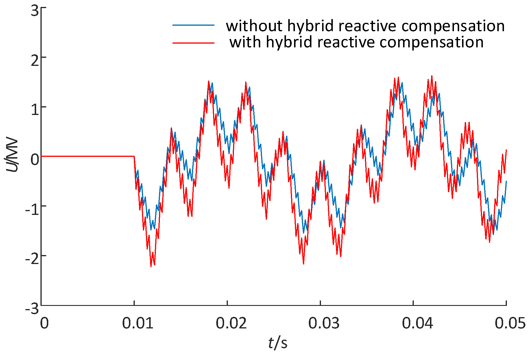
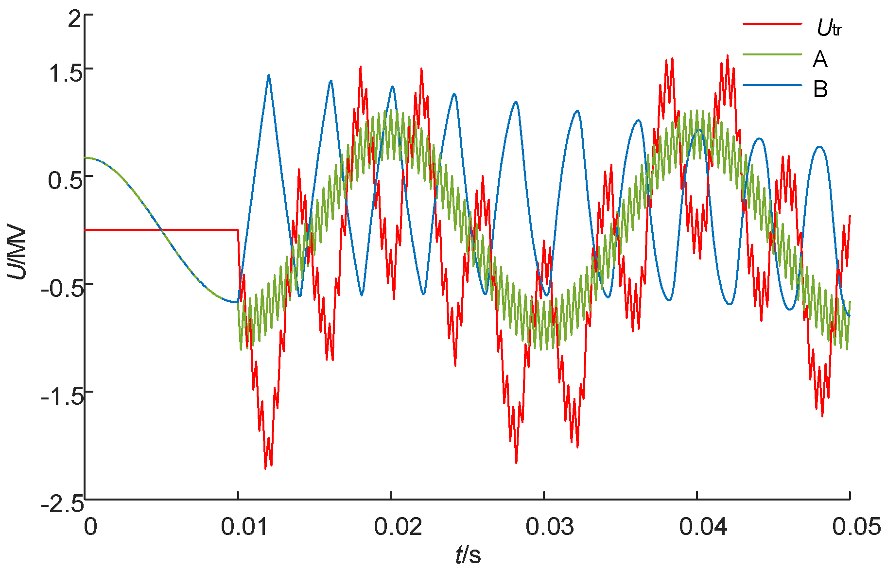
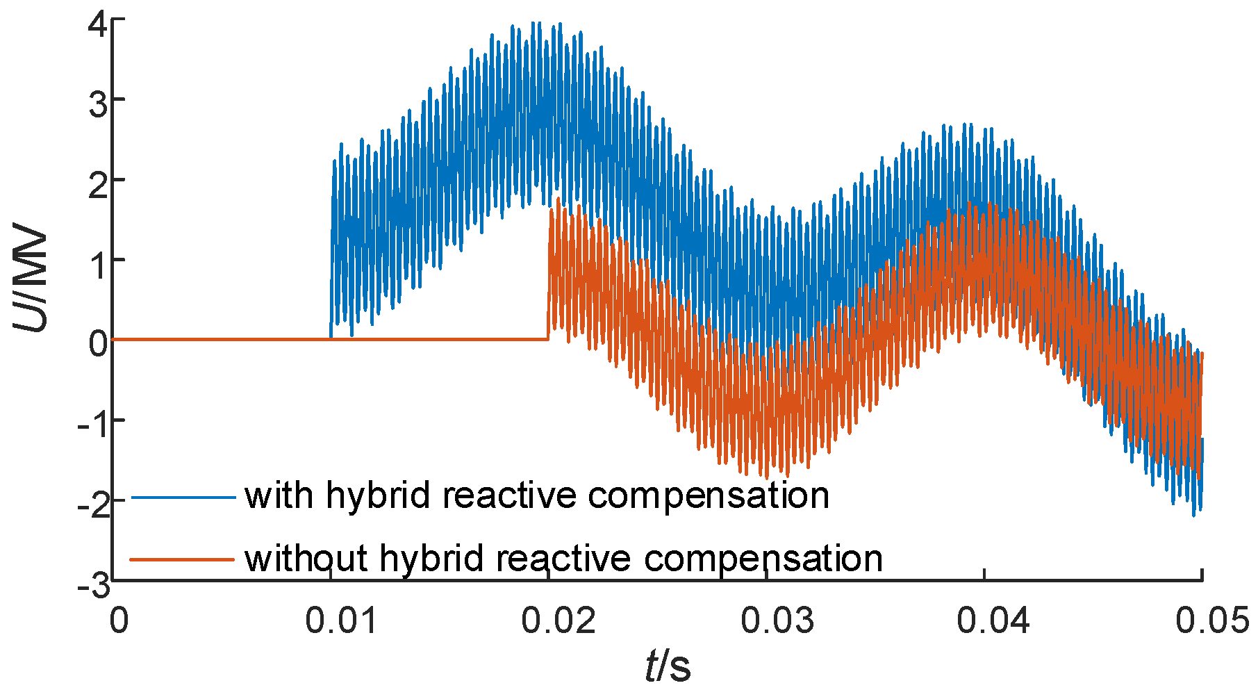
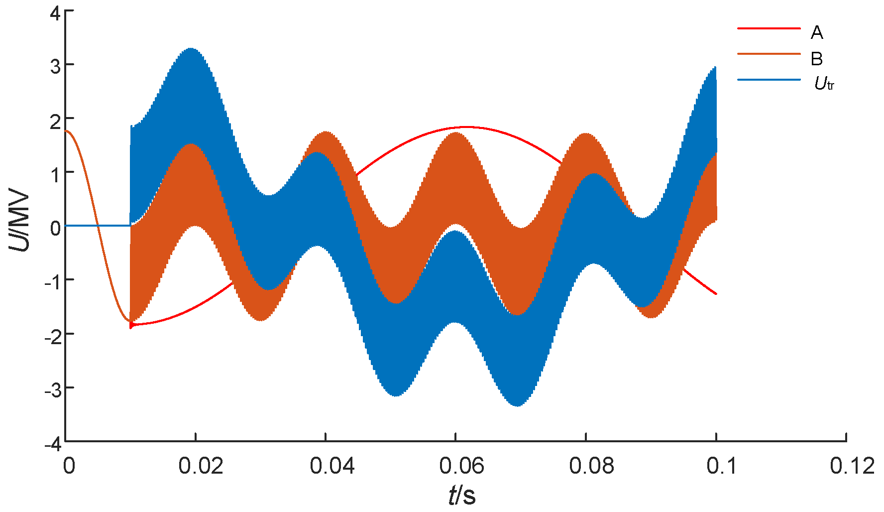
The parameters listed in Table 1 detail the TRV of the circuit breakers in the UHV transmission line with HRPC at an out-of-phase fault. When the out-of-phase fault current crosses zero, the circuit breaker opens. The TRV is determined by the value and distribution of the inductors, capacitors, and resistance in the circuit. Therefore, a considerable difference exists in the waveforms of the TRV in interrupting the out-of-phase faults, both with and without HRPC. The TRV waveforms of the circuit breaker in the UHV power system, with and without the installation of HRPC, are compared in Figure 3. The position of Points A and B are demonstrated in Figure 2, where Utr is the transient overvoltage between A and B.
From Figure 3, the voltage appears across the pole contacts when the breaker opens at 0.01 s. During the interrupting process of the UHV transmission line during out-of-phase faults, the peak TRV value increases rapidly after installing HRPC, from 1451.5 to 2360.9 kV. The RRRV obviously increases, from 0.74 to 1.24 kV/μs. After the current interruption, each system oscillates independently when a circuit breaker connects the two power systems. The t values are different for both oscillations, as shown in Figure 4, and the increase time for the TRV across the circuit breaker utr will mainly depend on the voltage of Point A. The results show that, after the installation of HRPC, the TRV and RRRV across the circuit breakers significantly increase, resulting in the difficult interruption of out-of-phase faults. The requirements for the insulation and stability of the system are also much higher. Therefore, the influence of the compensation degrees on the RRRV of the circuit breakers must be studied to optimize the configuration plan of both series compensation and controlled shunt reactors.

3.2. Theoretical Computation for Out-of-Phase Faults

To study the difference between the interrupting characteristics of out-of-phase faults before and after the installation of HRPC, analyzing the TRV of circuit breakers during out-of-phase faults is necessary to prove the accuracy of our simulation results.
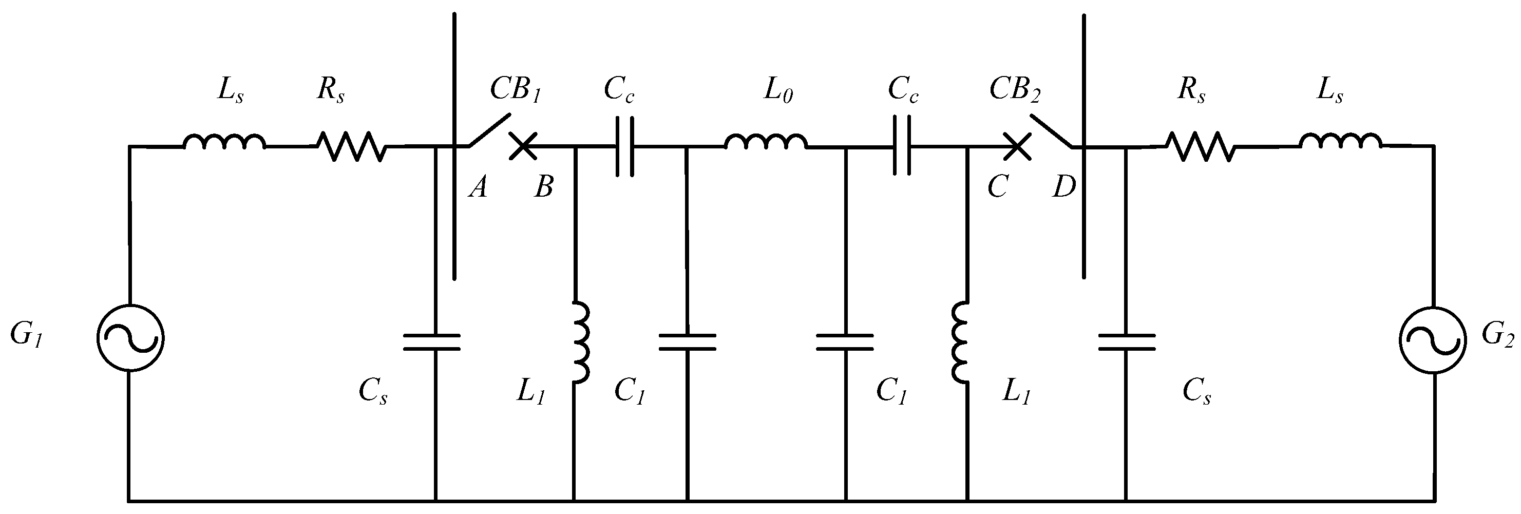
The equivalent TRV calculation circuit during the out-of-phase fault is shown in Figure 5, where G1 and G2 are the power supply, Um is the amplitude of power supply phase voltage, Up is the effective value of the power supply phase voltage, CB1 and CB2 are circuit breakers, Ls, Rs, and Cs represent the source side inductance, resistance, and capacitance-to-ground, respectively, Cc and L1 are the equivalent elements of series compensation and the inductance of the shunt reactor, respectively, and L0 and C1 are the line inductance and capacity, respectively.
Assuming that the inductance and capacitance-to-ground per unit length of a transmission line are represented by l1 and c1, respectively, and the length of the line is s, the inductance and capacitance-to-ground of transmission line are L0 = l1s and C1 = c1s, respectively. The fault current Iop can be demonstrated as follows:
I o p = 2 U p 4 R s 2 + ( 2 ω L s 2 ω C c + ω L 0 ) 2 2 U p 2 ω L s 2 ω C c + ω L 0
where ω is the angular frequency of the power supply. Cc and Cs are connected by the switching arc of the circuit breaker CB1 before it extinguishes. Considering that the arc voltage is generally low, the voltage of Cs and Cc are equal to ua and ub, respectively. As the switching arc current passes zero, ua and ub arrive at their peak values, UAm and UBm, respectively.
U A m = U B m 2 U p ( ω L s 2 ω C c + ω L 0 ) 2 ω L s 2 ω C c + ω L 0 .
Due to the series resonance between Ls and Cs, the frequency of voltage oscillation at Point A is given by
ω 1 = 1 / L s C s .
Since the TRV exists for only a short time period, and the power frequency changes little during that period, uA can be approximately represented as
u A = U m cos ω t + ( U m U A m ) cos ω 1 t .
Using this method, the voltage at the other end of the transmission line is shown as
u D = U m cos ω t ( U m U A m ) cos ω 1 t .
After the termination of the circuit fracture arcs at both ends of the line, different voltage oscillations occur at both ends of the circuit breaker. Because of the capacitance of the series compensation devices and shunt reactor, the voltage of the series compensation uCc oscillates, and the oscillation frequency is
ω 2 = 1 L 1 C c .
The voltage of series compensation can be shown as
u C c = 2 I o p ω C c cos ω 2 t .
Due to the distributed parameters of a transmission line, the voltage on the line is a traveling wave in sawtooth waveform. Its cycle T3 is two times that of the travelling wave travel time along the line. Neglecting the line loss, the speed of travelling wave is
T 3 = 2 s l 1 c 1 .
The initial value of the transmission line voltage uL is ULm, decreasing to −ULm after a half period. Thus, the decreasing voltage rate of uL in a half cycle is
d u L d t = 2 U L m s l 1 c 1 = 2 2 I o p ω ( l 1 s ) s l 1 c 1 = 2 2 I o p ω Z 0
where Z 0 = l 1 c 1 , U L m = 2 I o p ω ( l 1 s ) .
Therefore, in the initial period, the variation of uL is
u L = { U L m 2 2 I o p ω Z 0 t f U L m + 2 2 I o p ω Z 0 ( t T 3 / 2 ) } ( t T 3 / 2 )
Based on the analysis above, the recovery voltage of the circuit breaker, after interrupting the out-of-phase faults, is
u t r = u A B = u A u B = u A 2 u C c + u L + u C .
The TRV increase rate of the circuit breaker RRRV can be shown as
R R R V = | V p | / t p
where tp is the time at which the recovery voltage reaches its first peak Vp. Substituting tp into Vp, we obtain
V p = u t r | t = t p u t r | t = 0 .
T1 is the voltage oscillation period of the source side capacitor, T2 is the voltage oscillation period of the series compensation and controlled shunt reactor, and T3 is the voltage oscillation period of the travelling wave in the transmission line. The minimum value among the above three variables is denoted as min (T1, T2, T3), so the oscillation period T0 of the initial part of recovery voltage is min (T1, T2, T3). We calculated that T3 had the lowest value. Thus, T0 equals T3.
t p = T 0 2 = min ( T 1 , T 2 , T 3 ) 2 = T 3 2 = s l 1 c 1 .
Assuming that the compensation degree of series capacitance is α,
Δ u L = 2 U m l 1 s 2 L s + s l 1 ( 1 α ) .
Applying this method, we supposed that the compensation degree of the stepped controlled shunt reactor is γ:
γ = X L 1 X C 1 = ω 2 L 1 c 1 s .
Substituting Equation (12) with the compensation degree of the series compensation and shunt reactor results in
R R R V = | Δ u A + Δ u C + Δ u L | t p
where
Δ u A = 2 U m [ cos ( 100 π s l 1 c 1 ) 1 ] + 2 U m L s [ cos ( s l 1 c 1 L s C s ) 1 ] 2 L s + s l 1 ( 1 α ) Δ u C = 2 U m α l 1 s [ cos ( ω 2 s 2 l 1 c 1 α γ 2 ) + 1 ] 2 L s + s l 1 ( 1 α ) Δ u L = 2 U m l 1 s 2 L s + s l 1 ( 1 α )
Equation (17) provides the RRRV computational method for transient recovery voltage in UHV power systems during out-of-phase faults. Assuming that L0 = 0.5 H, Cs = 0.05 μF, α = 0.4, and γ = 0.44, these parameters are substituted into Equation (17). The RRRV of the transient recovery voltage is 1.19 kV/μs from the calculation, and the simulation value is 1.24 kV/μs, which is generally consistent with the calculated result.
By computing different compensation degrees, the relationship between RRRV and the degrees of series compensation in different lengths of transmission lines is shown in Figure 6. The different lengths of transmission lines have an obvious effect on the values of RRRV with changing compensation degrees. Once the series compensation degrees exceed 0.5, the increase in the speed of the RRRV values accelerates and exceeds the peak value established by the 1100 kV circuit breaker national standard in China. By comparing different lengths of transmission lines, when the degree of compensation is certain, the RRRV values decrease with the increase in line length, meaning that, when the length of transmission line is short, the RRRV is not limited.
As a result, the decreasing series compensation degree hampers the RRRV across circuit breakers, especially when the compensation degree is about 0.5, and the transmission line can be extended under the economic and project requirements to decrease RRRV.
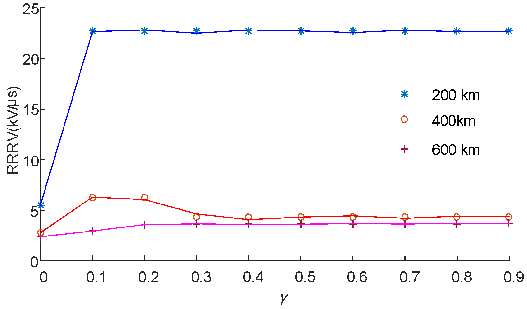
Despite the degree of series compensation, the RRRV hardly changed with the compensation degree of the stepped controlled shunt reactor. A compensation degree of zero means the controlled shunt reactors were not installed. As shown in Figure 7, the compensation degree of the controlled shunt reactor has little influence on the RRRV values, which provides favorable conditions for stepped controlled shunt reactors. To optimize the interrupting characteristics of circuit breakers at out-of-phase faults, the compensation degree of the controlled shunt reactor does not need to be considered. Additionally, the compensation degree of the controlled shunt reactor has some influence on the RRRV values when the transmission line is different lengths. When the length of the transmission line is 200 km, the RRRV values increase to about five times that of the other two cases. Computation results showed that no linear relationship exists between the length of the transmission line and RRRV, but the value of RRRV decreases with the increase in total line length.

4. Circuit Breaker RRRV at Short-Line Fault

4.1. Simulation Analysis for Short-Line Faults

With the increase in power system capacity, severe accidents occur occasionally when the circuit breaker cannot interrupt the short-line faults. After the installation of HRPC in UHV systems, the ability of the circuit breaker to interrupt the short-line current can be analyzed by simulation. The TRV simulation waveforms of the circuit breaker, before and after the installation of HRPC, are shown in Figure 8.
From Figure 8, during the interrupting process of UHV transmission line at short-line faults, the TRV value across the circuit breaker significantly increases after installing HRPC, from 1748.7 to 1867.1 kV. The short-line fault is mainly characterized by a fast-rising line-side transient, as seen in Figure 9. As a result, the installation of HRPC can restrain the transient process since the value of TRV without HRPC is twice as much as the one with HRPC. Furthermore, from the calculation of the TRV, the RRRV also increased from 10.47 kV/μs to 11.24 kV/μs. In this situation, the capacitor breaker is unlikely to successfully open. The results show that, after the installation of HRPC in an UHV transmission line, the TRV and RRRV increase significantly, causing difficulties for interrupting the fault, placing a higher requirement on the insulation and stability of the system. Therefore, the relationship between the compensation degree of HRPC and RRRV should be analyzed, and an improved HRPC configuration plan should be obtained to limit RRRV to a safe value.

4.2. Theoretical Computation for Short-Line Faults

To determine the difference between the interrupting characteristics of circuit breakers at short-line faults before and after the installation of HRPC, analyzing the TRV of circuit breakers during short-line faults is necessary.
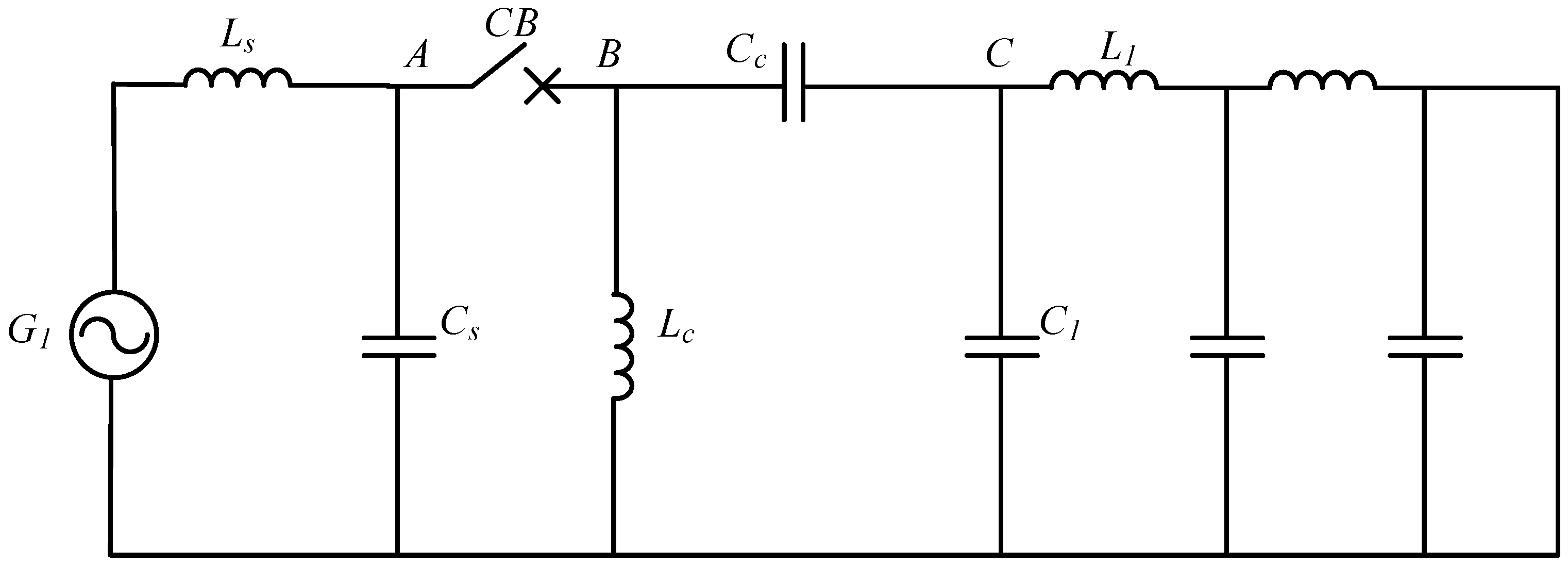
An equivalent circuit diagram, after the simplification of short-line faults, is shown in Figure 10. L1 and C1 are the inductance and shunt capacitance at line side, respectively. The fault occurs 10 km away from the circuit breakers, so L1 = l1s and C1 = c1s.
When the interrupting arc of circuit breaker is terminated, uA, uBC, and uC reach their peak values of UAm, UBC, and UCm, respectively. Their values can be obtained as follows:
I s s = U p ( ω L s + ω L c ω 3 L 1 L c C c 1 ω 2 L c ( C c + C s ) ω 2 L 1 C c + ω 4 L 1 L c C c C s ) 2
U A m = 2 I s s ( ω L c ω 3 L 1 L c C c ) 1 ω 2 L c ( C c + C s ) ω 2 L 1 C c + ω 4 L 1 L c C c C s
U B C = U A C = U A m U C m
U C m = 2 I s s ω L 1 .
After the extinction of the interrupting arc, the voltage at the above three points should be separately analyzed. After the extinction, an oscillation in the variation of voltage occurs at Point A.
From the comparison, we concluded that uA can be demonstrated as follows:
u A = U p cos ω t + 2 I s s ω L s cos ω 1 t
where ω1 is the oscillation frequency at the power supply side, and series resonance occurs between Ls and Cs:
ω 1 = 1 L s C s .
From observation and analysis, these oscillations include the oscillation between series compensation Cc and shunt reactance Lc, assuming that its oscillation frequency is
ω 2 = 1 L c C c .
Therefore, the variation of uBC is demonstrated as
u B C = U B C cos ω 2 t .
For Point C, oscillation only occurs between the shunt capacitance at line side and inductance, and the fault line has distributed characteristics. Therefore, a sawtooth process occurs, and its period T3 is four times that of the travelling wave passing the fault line. Ignoring the line loss, the oscillation cycle of sawtooth wave is
T 3 = 4 s l 1 c 1 = 4 L 1 C 1 .
Therefore, the variation of the voltage at Point C is
u C = U C m cos ω 3 t .
The recovery voltage of the circuit breaker in a short-line fault is
u t r = u A u B C u C = U m cos ω t + 2 I s s L s ω cos ω 1 t U B C cos ω 2 t + U C m cos ω 3 t .
Using this process, we concluded that
t p = T 0 2 = min ( T 1 , T 2 , T 3 ) 2
where T1 is the voltage oscillation period of capacitance at source side, T2 is the voltage oscillation period of series compensation, and T3 is the voltage oscillation period of the travelling wave in the fault line. Generally, T2 > T1 and T2 > T3. When the distance of the short-line fault is relatively short, T1 > T3.
Thus,
t p = T 0 2 = min ( T 1 , T 2 , T 3 ) 2 = T 3 2 = 2 L 1 C 1 .
We observed that the first peak value of the recovery voltage is
V p = U m cos ω t p + 2 I s s ω L s cos ω 1 t p U B C cos ω 2 t p + U C m cos ω 3 t p ( U p + 2 I s s ω L s 2 U B C + U C m ) .
From the formulas above and our related analysis, we concluded that, when the short-line fault occurs at s km, the RRRV equation is
R R R V = | Δ u A + Δ u B C + Δ u C | t p
where
Δ u A = 2 L s U P ( 1 cos 2 s 2 l 1 c 1 L s C s ) ( L s + γ ω 2 s c 1 ( 1 2 β ) 1 2 β γ s c 1 ( 2 ω 2 s l 1 β + C s + 2 C s β ) ) U p ( cos 2 ω s 2 l 1 c 1 1 ) Δ u B C = ( 2 γ ω s c 1 ( 1 2 β ) 1 γ s c 1 ( 2 ω 2 s l 1 β + C s ) 2 β + 2 γ C s s c 1 β 2 ω s l 1 ) ( 1 cos 2 s 2 l 1 c 1 ω 2 β 2 γ ) U p ( ω L s + ( β 2 ) s γ ω 2 γ 2 l 1 c 1 β ω 2 s l 1 c 1 β γ C s 2 ω 2 s 2 l 1 c 1 + 2 ω 2 s l 1 c 1 γ C s 2 γ ) 2 Δ u C = 2 2 s l 1 U p ( L s + ( β 2 ) s γ ω 2 γ 2 l 1 c 1 β ω 2 s l 1 c 1 β γ C s 2 ω 2 s 2 l 1 c 1 + 2 ω 2 s l 1 c 1 γ C s 2 γ ) 2 .
With the increase in short line distance, the value of T3 increases. Since T3 > T2, the change in wave voltage is approximated as sine functions, in accordance with
t p = T 0 2 = min ( T 1 , T 2 , T 3 ) 2 = T 1 2 = π L s C s .
The new expression of the recovery voltage can be shown as follows:
R R R V = U m cos ω π L s C s + 2 I s s ω L s cos ω π L s C s U B C cos ω 2 π L s C s π L s C s U C m cos ω 3 π L s C s + ( U p + 2 I s s ω L s U B C + U C m ) π L s C s .
After installing HRPC, when short-line faults occur at s km of the transmission line, the RRRV of circuit breaker is
R R R V = | Δ u A + Δ u B C + Δ u C | t p
where
Δ u A = 2 L s U P ( L s + ( β 2 ) s γ ω 2 γ 2 l 1 c 1 β ω 2 s l 1 c 1 β γ C s 2 ω 2 s 2 l 1 c 1 + 2 ω 2 s l 1 c 1 γ C s 2 γ ) 2 U p ( cos ( ω π L s C s ) 1 ) Δ u B C = ( 2 γ ω s c 1 ( 1 2 β ) 1 γ s c 1 ( 2 ω 2 s l 1 β + C s ) 2 β + 2 γ C s s c 1 β 2 ω s l 1 ) ( 1 cos 2 s 2 l 1 c 1 ω 2 β 2 γ ) U p ( ω L s + ( β 2 ) s γ ω 2 γ 2 l 1 c 1 β ω 2 s l 1 c 1 β γ C s 2 ω 2 s 2 l 1 c 1 + 2 ω 2 s l 1 c 1 γ C s 2 γ ) 2 Δ u C = 2 s l 1 U p ( 1 cos π 2 2 s L s C s l 1 c 1 ) ( L s + ( β 2 ) s γ ω 2 γ 2 l 1 c 1 β ω 2 s l 1 c 1 β γ C s 2 ω 2 s 2 l 1 c 1 + 2 ω 2 s l 1 c 1 γ C s 2 γ ) 2 .
Equations (32) and (35) demonstrate the RRRV computational methods for short-line faults in UHV power system, with and without the installation of HRPC. By comparing these equations, the value of the RRRV across breakers with HRPC is relatively higher than without HRPC, which corresponds to our simulation results. Assuming that the transmission line parameters and HRPC are the same as those mentioned above, these parameters are substituted into Equation (35). The RRRV of the transient recovery voltage is 14.47 kV/μs from the calculation, which is generally consistent with the simulated result.
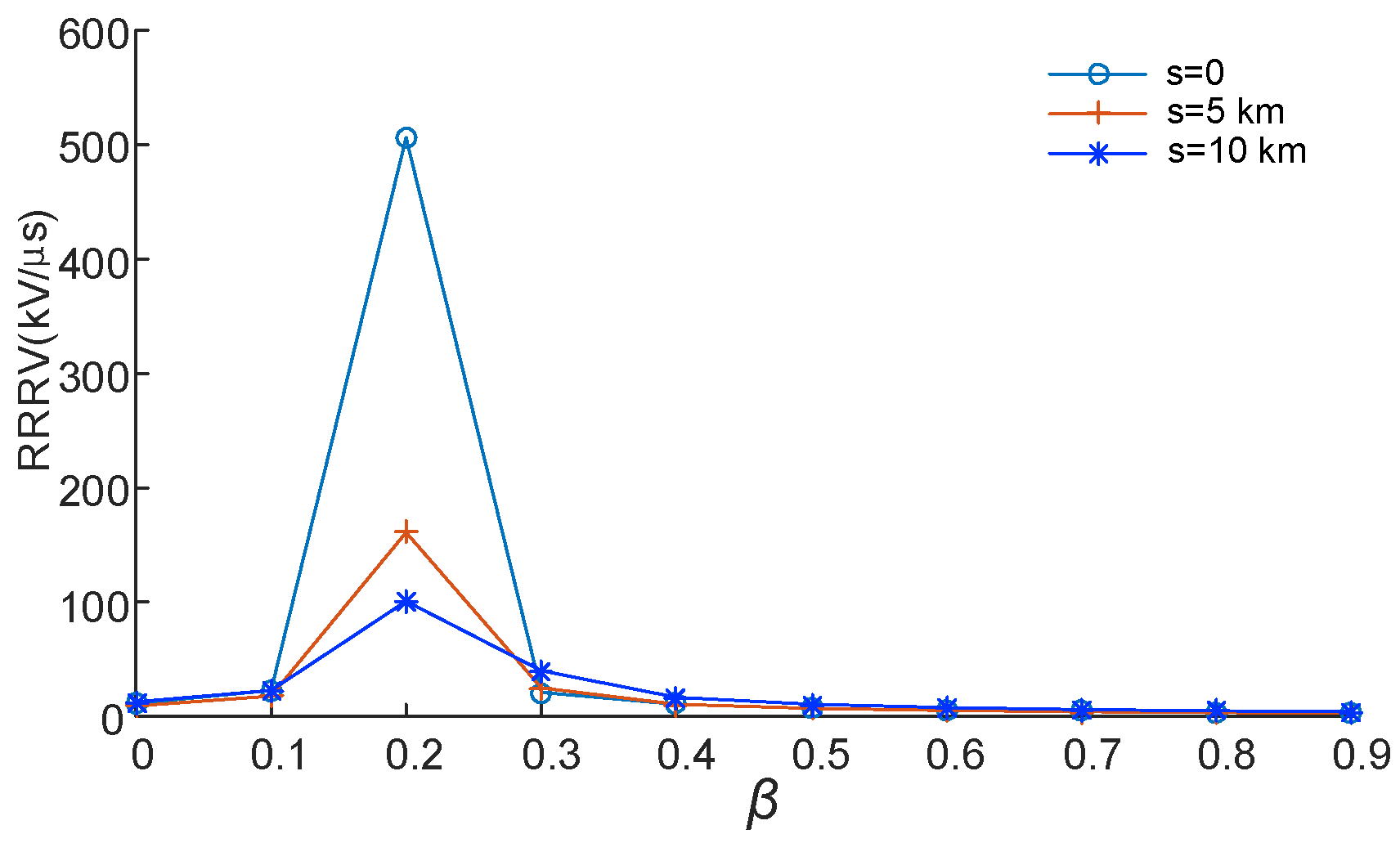
The computation results in Figure 11 show the variation in RRRV with the compensation degree of HRPC. By comparing the three kinds of fault distance, when the short circuit point is less than 10 km from the generator outlet, the RRRV slowly increases from a compensation degree of zero, reaching its peak value when the compensation degree is about 0.2, around 500 kV/μs. From the analysis of the circuit model and parameters, the resonance occurs in the circuit consisting of the shunt reactor when the compensation degree of the series compensation is 0.2 or so, leading to the appearance of peak voltage. Therefore, this series compensation degree value should be avoided during the process of HRPC configuration.
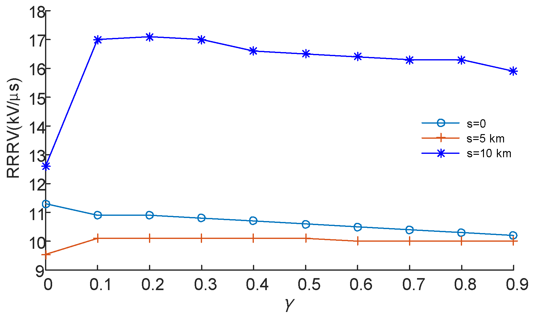
From Figure 12, the variation in the controlled shunt reactor compensation degree has little effect on the RRRV after installing the controlled shunt reactors, and with the increase in compensation degree, the RRRV does not change. Similar to the occurrence of out-of-phase faults, during a short-line fault, there is no fixed variation trend in RRRV with different fault distances.

5. Conclusions

The installation of HRPC in transmission lines increases the TRV for different transmission line faults, creating a need for the study of the interruption characteristics of circuit breakers. From our simulation, the fault currents may show low frequency oscillation, high amplitude, and DC bias after the installation of HRPC in UHV transmission lines.
When the out-of-phase faults occur in UHV transmission lines installed with HRPC, the RRRV across the circuit breaker increases with the increase in the degree of series compensation, but the compensation degree of the shunt reactor has little effect on RRRV. Once the series compensation is settled, no meaningful linear relationship exists between the length of the transmission line and RRRV, but the value of RRRV decreases with the increase in total line length. As for short-circuit faults, the RRRV value of RRRV peaks when the series compensation degree is 0.2 due to resonance, and RRRV changes little with the variation in both series compensation and shunt reactor compensation degrees. However, RRRV changes little with the length of the transmission line if the compensation degree of HRPC is fixed. Notably, all results from the simulation were proved in the theoretical computation.
The configuration scheme can be optimized using the calculations for out-of-phase and short-line faults. Selecting the appropriate series compensation degree can restrain the RRRV across circuit breakers. Especially when the compensation degree of the stepped controlled shunt reactor is about 0.44, a series compensation degree of 0.2 should be avoided to prevent resonance. In addition, the transmission line can be properly extended under the economic and project requirements to decrease RRRV.

Acknowledgments

Financial support from the National Science Foundation of China (51507095) and the China Postdoctoral Science Foundation (2015M572032) are here acknowledged.

Author Contributions

Hongshun Liu conceived and designed the simulation and computation. Zhen Wang and Jingjing Yang wrote the paper. Bin Li, Ang Ren and Qiuxia Wang revised it.

Conflicts of Interest

The authors declare no conflict of interest.

References

  1. Liu, Z.Y. Innovation of UHV AC transmission technology in China. Power Syst. Technol. 2013, 37, T1–T8. [Google Scholar] [CrossRef]
  2. Huang, D.C.; Shu, Y.B.; Ruan, J.J.; Hu, Y. Ultra high voltage transmission in China: Developments, current status and future prospects. Proc. IEEE 2009, 97, 555–583. [Google Scholar] [CrossRef]
  3. Li, Q.M.; Liu, H.S.; Lou, J.; Zou, L. Impact research of inductive FCL on the rate of rise of recovery voltage with circuit breakers. IEEE Trans. Power Deliv. 2008, 23, 1978–1985. [Google Scholar] [CrossRef]
  4. Oshita, Y.; Hirasawa, K.; Kurosawa, Y. Investigation of an SF6 ultra high voltage circuit breaker using an opening resistor and auxiliary interrupter. IEEE Trans. Power Deliv. 1992, 7, 346–352. [Google Scholar] [CrossRef]
  5. Das, J.C. Reducing interrupting duties of high-voltage circuit breakers by increasing contact parting time. IEEE Trans. Ind. Appl. 2008, 44, 1027–1033. [Google Scholar] [CrossRef]
  6. Rai, D.; Faried, S.O.; Ramakrishna, G.; Edris, A.A. An SSSC-based hybrid series compensation scheme capable of damping subsynchronous resonance. IEEE Trans. Power Deliv. 2011, 27, 531–540. [Google Scholar] [CrossRef]
  7. El-Marsafawy, M. Application of series-capacitor and shunt-reactor compensation to an existing practical AC transmission line. IEE Proc. Gener. Trans. Distrib. 1991, 138, 330–336. [Google Scholar] [CrossRef]
  8. Elenius, S.; Uhlen, K.; Lakervi, E. Effects of controlled shunt and series compensation on damping in the nordel system. IEEE Trans. Power Syst. 2005, 20, 1946–1957. [Google Scholar] [CrossRef]
  9. Cai, H.S.; Hu, D.H.; Tu, C.Q.; Li, M.; Zhu, L.; Huang, B.J.; Yao, S.L. Study on the shunt compensation and overvoltage in Zhengnan 500 kV System. High Volt. Eng. 2000, 26, 58–60. [Google Scholar]
  10. Xu, L.; Sheng, Z.; Fu, G.; Gao, G.; Benfatto, I.; Mankani, A.D.; Tao, J. The reactive power compensation and harmonic filtering and the over-voltage analysis of the ITER power supply system. In Proceedings of the 2010 Twenty-Fifth Annual IEEE, Applied Power Electronics Conference and Exposition (APEC), Palm Springs, CA, USA, 21–25 February 2010; pp. 1622–1626. [Google Scholar] [CrossRef]
  11. Indulkar, C.S.; Viswanathan, B.; Venkata, S.S. Maximum power transfer limited by voltage stability in series and shunt compensated schemes for AC transmission systems. IEEE Trans. Power Deliv. 1989, 4, 1246–1252. [Google Scholar] [CrossRef]
  12. Na, H.; Li, Y.M.; Wei, Z.Y.; Li, W.Z.; Yao, L.; Yao, S.L. Analysis and study on out-of-phase fault of circuit breaker’s break-off with opening resistance. Electrotech. Electr. 2011, 12, 13–18. [Google Scholar]
  13. International Electrotechnical Commission. High-Voltage Switchgear and Controlgear—Part 100: High-Voltage Alternating-Current Circuit-Breakers; IEC62271; International Electrotechnical Commission: London, UK, 2001. [Google Scholar]
  14. Zheng, B.; Xiang, Z.T.; Ban, L.G.; Gu, N.H.; Wang, X.T.; Han, B. Analysis on circuit breaker transient recovery voltage UHV AC transmission lines fixed with series capacitors. High Volt. Eng. 2013, 39, 605–611. [Google Scholar] [CrossRef]
  15. Zhang, Y.Y.; Ban, L.G.; Xiang, Z.T.; Lin, J.M.; Zheng, B.; Zhang, Y.P.; Han, B.; Han, Y.N. Research on working condition of key components for fixed series compensation in 1000 kV UHV AC power transmission project. Power Syst. Technol. 2013, 37, 2218–2224. [Google Scholar]
  16. Liu, H.S.; Lv, T.T.; Han, M.M.; Li, B.; Wang, G.; Li, Q.Q. Overvoltage amplitude and frequency characteristics of energizing off-load UHV transmission line with hybrid reactive compensation. Power Syst. Technol. 2015, 39, 1970–1976. [Google Scholar] [CrossRef]
  17. Ma, Q.Y.; Zheng, B.; Ban, L.G.; Xiang, Z.T. Secondary arc current analysis of an untransposed EHV/UHV transmission line with controllable unbalanced shunt reactor. IEEE Trans. Power Deliv. 2014, 30, 127–135. [Google Scholar] [CrossRef]
  18. Zhou, P.H.; He, H.W.; Dai, M. Application of controllable reactors to 1000 kV AC compact transmission line. High Volt. Eng. 2011, 37, 127–135. [Google Scholar] [CrossRef]
  19. Tian, M.M.; Yin, J.N.; Liu, Y.B. Magnetic integration technology in controllable reactor of transformer type constituted by various magnetic materials. IEEE Trans. Appl. Supercond. 2014, 24, 1–5. [Google Scholar] [CrossRef]
  20. Rifaat, R.; Lally, T.S.; Hong, J. Circuit Breaker Transient Recovery Voltage Requirements for Medium-Voltage Systems with NRG. IEEE Tran. Ind. Appl. 2014, 50, 309–316. [Google Scholar] [CrossRef]
  21. Wei, X.; Zhou, Z.C.; Xie, T.X.; Tao, F.; Liu, Y.; He, J. Analysis and protection against overvoltages caused by vacuum circuit breakers switching on shunt capacitors. High Volt. Eng. 2014, 40, 3193–3198. [Google Scholar] [CrossRef]
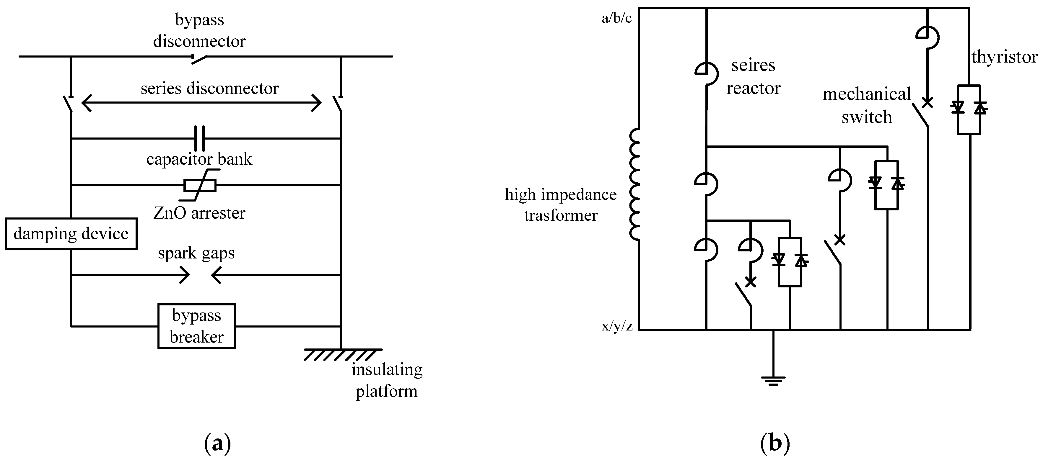
Figure 1. Structure of hybrid reactive power compensation: (a) series compensation and (b) stepped controlled shunt reactor.
Energies 11 00100 g001
Figure 2. Equivalent circuit of an ultra-high voltage (UHV) system with hybrid reactive power compensation (HRPC).
Energies 11 00100 g002
Figure 3. Transient recovery voltage (TRV) waveforms of circuit breakers at out-of-phase faults.
Energies 11 00100 g003
Figure 4. The voltage at both ends of the circuit breakers at the out-of-phase faults.
Energies 11 00100 g004
Figure 5. Equivalent calculation circuit of TRV during the out-of-phase fault.
Energies 11 00100 g005
Figure 6. Relationship between rate-of-rise of recovery voltage (RRRV) and different compensation degrees of series compensation.
Energies 11 00100 g006
Figure 7. Relationship between RRRV and different compensation degrees of controlled shunt reactor.
Energies 11 00100 g007
Figure 8. The TRV waveforms of the circuit breaker in short-line faults.
Energies 11 00100 g008
Figure 9. The TRV waveform of circuit breaker at both ends of the line in short-line faults.
Energies 11 00100 g009
Figure 10. Equivalent circuit diagram for a short-line fault.
Energies 11 00100 g010
Figure 11. The short-line faults RRRV of the circuit breaker versus the compensation of series compensation.
Energies 11 00100 g011
Figure 12. The short-line faults RRRV of the circuit breaker versus the compensation degree of the shunt reactor.
Energies 11 00100 g012
Table 1. The main parameters of a 1000 kV transmission line.
SequenceR/(Ω·km−1)L/(mH·km−1)C/(μF·km−1)
Positive Sequence0.007830.834080.01379
Zero Sequence0.196372.673660.00846