1. Introduction
For a long time, several active and passive methods have been adopted by human beings to improve thermal comfort and reduce temperature fluctuation in buildings. Some of these methods include changes in construction material, its thickness, changes in geometry and changes in the orientation of the building. More common methods these days include the installation of heating and air conditioning systems which result in more energy consumption. It is believed that the building sector currently accounts about 30–40% of total energy use worldwide [
1]. Furthermore, the energy consumption of commercial and residential buildings is still increasing with the changes in working style, living standards, and climatic changes. Therefore the design of energy-efficient buildings that result in the reduction of energy consumption has become a highly concerning issue due to the limited reserves of fossil fuel, environmental issues, global warming, and energy crisis.
One of the interesting methods of reducing energy demand in buildings is to use a phase change material (PCM) for thermal energy storage. These materials have the ability to absorb and release massive amounts of energy during phase transitions with small temperature change. A lot of work has been done for thermal comfort improvement and reduction of energy consumption in buildings by integration of PCMs [
2,
3,
4,
5,
6,
7]. Osterman et al. [
8] presented a study on PCM thermal storage systems of buildings for space heating and cooling on an annual basis using 30 plates filled with paraffin. Thiele et al. [
9] demonstrated that addition of a PCM to the exterior wall in average size home results in a reduction of annual cooling load in Los Angeles and San Francisco from 53% to 82% and 85% to 100%, respectively. Diaconu and Cruceru [
10] carried out a simulation of a three functional layer wall with two different PCM wallboards as outer layers and polystyrene thermal insulation board as the middle layer. During the summer season the outer layer with higher melting temperature is active whereas during the winter season the internal layer PCM is active. The arrangement results in reduction of annual cooling and heating load by 1% and 12.8%, respectively, and peak cooling and heating load reduction by 35.4%.
Darkwa and Callaghan [
11] carried out a simulation study of a solar passive building with two different methods of PCM integration in the walls: (i) randomly mixed PCM board (ii) laminated PCM board. The results showed that the laminated PCM sample with a narrow phase change zone was capable of increasing the minimum room temperature by 3–4 °C more than the randomly-mixed type. Zwanzig et al. [
12] examined the thermo-physical behavior of composite PCM wallboard integrated into the roof and walls of a building across different environmental zones in the USA. It was observed that for better performance, the location of the PCM in the building envelope plays an important role and can result in the reduction of energy consumption in the building for all months of the year. Mathiev-Potvin and Gosselin [
13] carried out a numerical analysis of 10 cm thick wall with a 0.5 cm thick PCM slab located between the wall. The result shows that heat flux through the PCM-integrated wall was minimum when the PCM was located close to the center of the wall and the PCM melting point was close to the preferred temperature inside the room. There was an energy reduction of 7% in the PCM-integrated wall compared to the wall made of insulation.
Tyagi et al. [
14] experimentally investigated the thermal performance of a test room having sixty PCM-based panels for cool energy storage. Under different conditions, the results show that even with active heating load a PCM-integrated system can maintain a comfortable temperature inside a room for a long duration. The system was found suitable for both active and passive space cooling applications. Ascione et al. [
15] investigated the thermal performance of refurbished wall insulated massive buildings having PCMs added to the inner side of the building envelope. The analysis was done in five different Mediterranean climatic conditions for a complete cooling season (1 May to 30 September). It was observed that the greatest cooling energy saving was achieved by a PCM of 3 cm thickness. Oliver [
16] carried out a study on gypsum board containing PCM to analyse the hydrothermal conditions of a building. The results showed that the heat capacity of compound material improved by 20% when the PCM percentage in the board was increased by 7%. Also, thermal energy stored in gypsum board with 45% PCM was five times and three times more than brick and common gypsum board of same unit mass, respectively. From the literature, it is observed that by using phase change materials the thermal performance of the building gets enhanced due to the reduction in the heat transfer rate. However, to the knowledge of the authors limited published literature has studied the thermal performance of building roofs with multiple PCM layers in a tropical climate using 3-D heat transfer analysis. The novelty of the present work includes a thermal performance evaluation of the building roof by comparing different characterization of PCM such as the thickness of a single PCM layer, phase transition temperature of the PCM, and the use of multi-layered PCMs with different thicknesses for tropical climate conditions. The optimization of these parameters is elemental to determine the potential of success of integration of PCMs in a building structure. The paper also presents monthly heat reduction rates and energy savings because of the integration of PCM layers (a single layer and double layers) in a building roof.
2. System Description and Mathematical Modelling
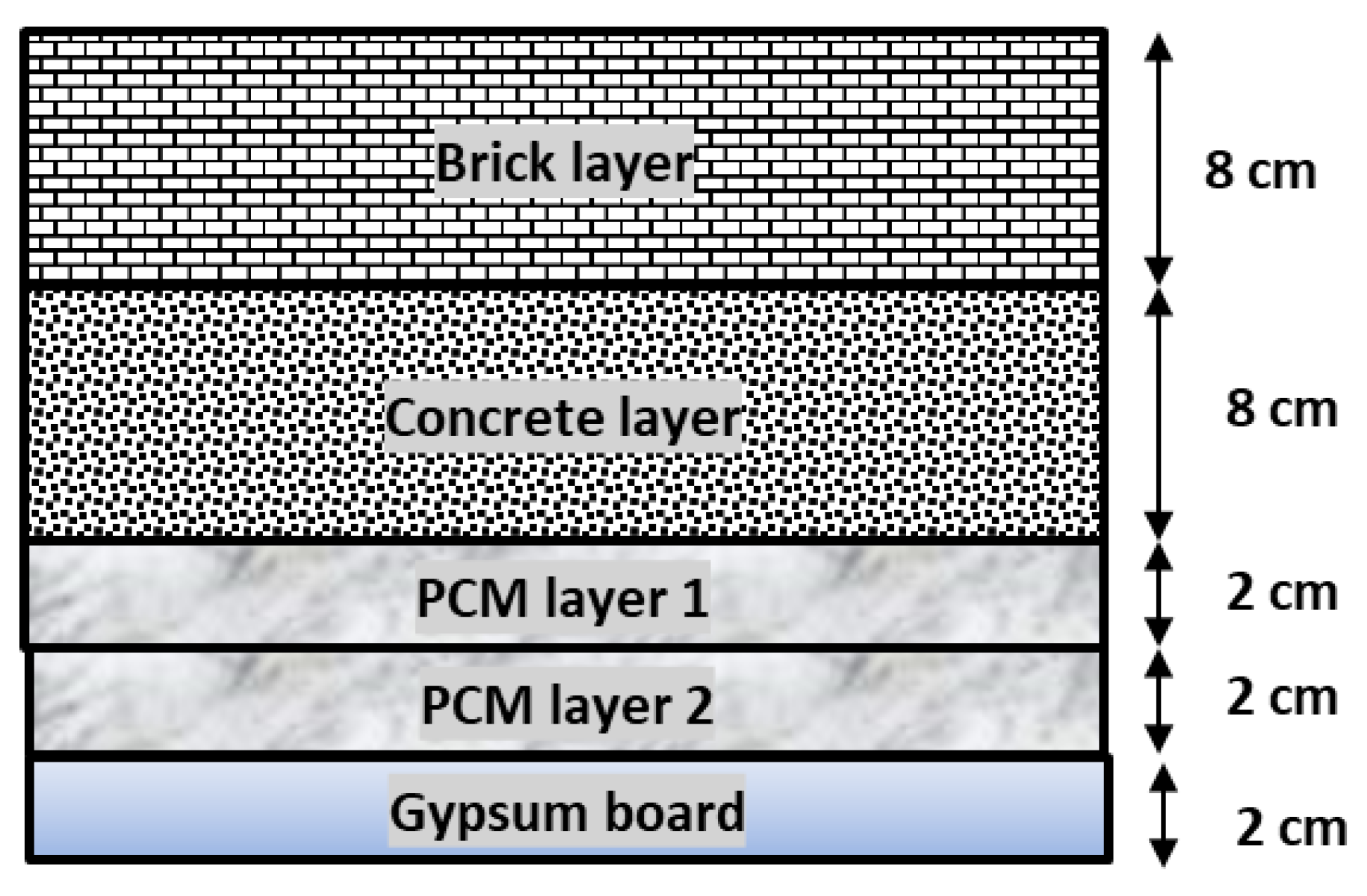
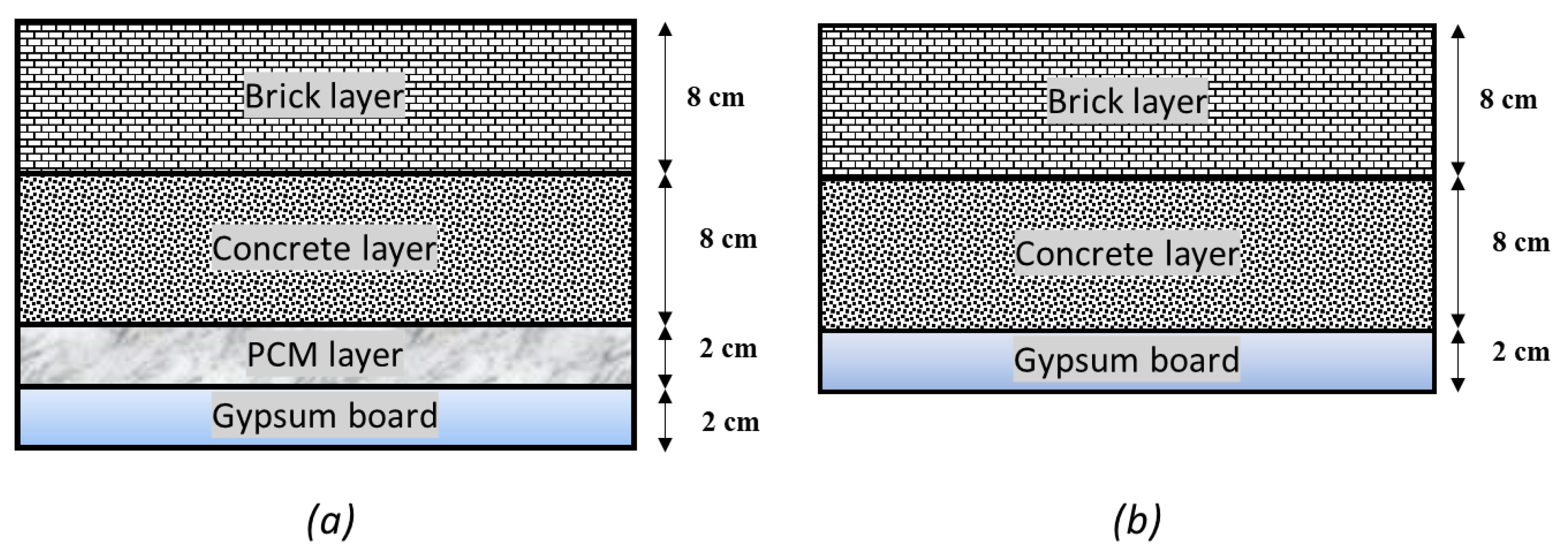
The modelling of the building roof is done for the tropical wet and dry climate location of Chennai, India whose latitude and longitude are 13.8°N and 80.27°E. The average low and average high temperature for the summer season are 23.8 °C and 36.9 °C, respectively, whereas for winter these temperatures are 20.9 °C and 30.5 °C, respectively. The temperature fluctuation at day and night time (7–9 °C) make PCM-based energy storage in roofs a very promising technique to maintain a comfortable temperature in the building envelope. A simplified single PCM layered roof model with length, breadth and thickness of 2 m, 1 m and 0.2 m, respectively, was modelled. The thickness of the roof was divided into four layers of different material. The geometry of the building roof is 3-D only with side along the thickness of the roof considered as adiabatic which makes the model 1-D. The topmost layer is a brick layer with the thickness of 0.08 m, the second layer is a concrete layer of thickness 0.08 m, the third layer is a PCM layer of thickness 0.02 m and the bottom-most layer is gypsum board of 0.02 m thickness. To determine the efficiency of integrating a PCM in the building roof in minimizing temperature variation and reducing heat gain another roof was modelled with similar geometry and structure layers but without a PCM layer. The construction details of the single PCM-integrated roof and the roof without a PCM layer are shown in
Figure 1.
Table 1 lists the physical properties of the different roof materials. The simulation has been carried out for the entire year to determine the effect of the PCM layer in the building roof in reducing heat gain and temperature at different roof layers.
Table 2 contains the climate data of Chennai for the entire year.
In order to determine the thermal response of energy storage in the PCM layer, it is important to analyse two processes: (i) the heat and energy transfer between the PCM layer and other roof layers (ii) heat and energy transfer within the PCM layer. Heat and energy transfer between the PCM and other roof materials can be evaluated by the heat transfer coefficient obtained by various correlations [
17,
18,
19]. In the PCM layer processes of solidification and melting occur during the night and day on a daily basis. During night time when there is no solar radiation and the ambient temperature is low, the PCM layer solidifies and stores cold energy. During the day time when there is solar radiation and the ambient temperature is high the PCM layer melts and releases its stored cold energy in the building envelope.
3. Governing Equations and Boundary Conditions
For the modelling of the roof the following assumptions are made: (i) the conduction of heat is considered to be one dimensional; (ii) the thermal conductivity of the brick layer, concrete layer, and gypsum board are considered to be constant; (iii) the PCM in the functional layer is considered to be isotropic and homogeneous; (iv) resistance at the interfacial surface is neglected; (v) surrounding radiation other than the sky is not considered. The heat gain/loss through walls, windows and floors, air infiltration and heat change because of occupancy are not considered in the study in order to evaluate the temperature raise/decline due to heat flow through the building roof. The three-dimensional transient energy equation for different structures of the roof other than PCM layer is given as:
where
T is temperature (K),
ρ,
Cp and
k are density (kg·m
−3), specific heat capacity (J·kg
−1·K
−1) and thermal conductivity (W·m
−1·K
−1) respectively. Subscript
j = 1 represents the brick layer,
j = 2 represents the concrete layer and
j = 3 represents the gypsum board layer.
Three-dimensional transient energy equation for the PCM layer based on the enthalpy porosity technique is given as:
where
h is the enthalpy (J·kg
−1).
The enthalpy of phase change material is computed as:
where
ho is the enthalpy (J·kg
−1) of the PCM at the reference temperature
To (K)
, m is the liquid ratio and
L is latent heat of the PCM (J·kg
−1).
For the solid phase
m = 0, so the enthalpy is:
During phase transition
m varies between 0 and 1, so the enthalpy is:
For the liquid phase
m = 1, so the enthalpy is:
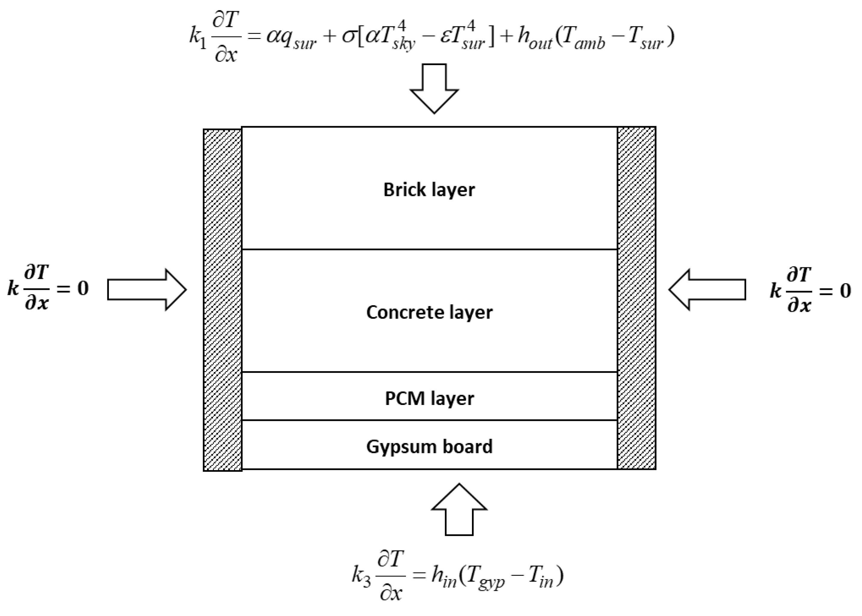
The boundary conditions for the considered model (
Figure 2) are given as follows:
The top section, that is the brick layer, is excited by both convection and radiation, with radiation being effective only during sunshine hours. The mathematical boundary condition for the top surface of the roof is given by:
where α is absorption coefficient of the surface,
qsur is heat flux at the surface due to solar radiation (W·m
−2), σ is the Stefan Boltzmann constant (σ = 5.67 × 10
−8 W·m
−2·K
−4), ϵ is surface emissivity.
Tsky,
Tsur,
Tamb are respectively the sky temperature (K), top surface temperature (K), ambient temperature (K) and h
out is outside convective heat transfer coefficient (W·m
−2·K
−1).
The sky temperature is given by [
20]:
The mathematical boundary condition for the bottom surface of the roof is given by:
where
hin,
Tgyp and
Tin are respectively indoor convective heat transfer coefficient (W·m
−2·K
−1), temperature of the base layer of gypsum board (K) and indoor room temperature (K).
The mathematical boundary condition for side vertical surfaces of the roof is given by:
5. Results and Discussion
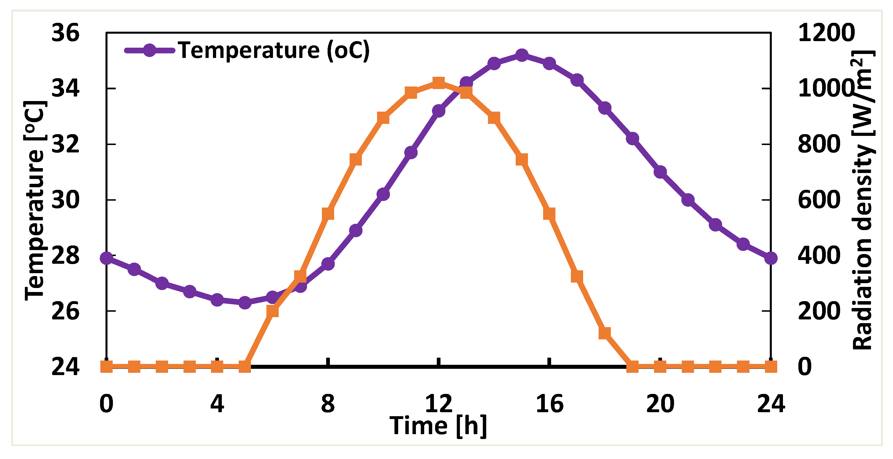
For modelling analysis, the length and breadth of the roof are respectively taken as 2 m and 1 m. The thickness of the brick layer, concrete layer, PCM layer and the gypsum board layer are respectively taken as 0.08 m, 0.08 m, 0.02 m, and 0.02 m. The hourly average ambient temperature and solar radiation density for the month of July are shown in
Figure 3 [
22]. The outside (
hout) and indoor (
hin) convective heat transfer coefficient are 5 W·m
−2·K
−1 and 1 W·m
−2·K
−1, respectively, calculated by the appropriate Nusselt correlation using the property values and climatic values given in the book by Tiwari [
22]. In the present numerical analysis, the outside (
hout) and indoor (
hin) convective heat transfer coefficients are considered constant throughout the day. The indoor room temperature is taken as 27 °C and the initial temperature of the system is 30.2 °C. The absorption coefficient of the surface α is 0.8 and surface emissivity ϵ is 0.9. The governing equations along with the boundary conditions are solved by finite volume method using an implicit scheme on the structured grid. The model has been solved using FLUENT Inc., FLUENT 15.0 User’s Guide; [
23]. The enthalpy porosity technique was used to determine the thermophysical properties of the phase change material in the roof structure. A time step of 2 s is used for the simulation and the simulation was run continuously for a few days (here it is 5 days) until the solution become periodic and the residual value is minimum. The variation of temperature in the building roof layer with time has been analyzed for different grid sizes (the distance between two successive nodes is termed as grid size). The results show that decreasing grid size beyond 1 mm does not improve the results much. The grid size of 1 mm is thus chosen for the simulation analysis in the present work.
5.1. Temperature Analysis of Different Roof Structure Layer
The temperature variation in different roof structure layers has been analyzed for a single PCM layer-integrated roof and a roof without PCM in detail for all the months of the year with PCM 302K (transition temperature 302 K), having a thickness of 2 cm.
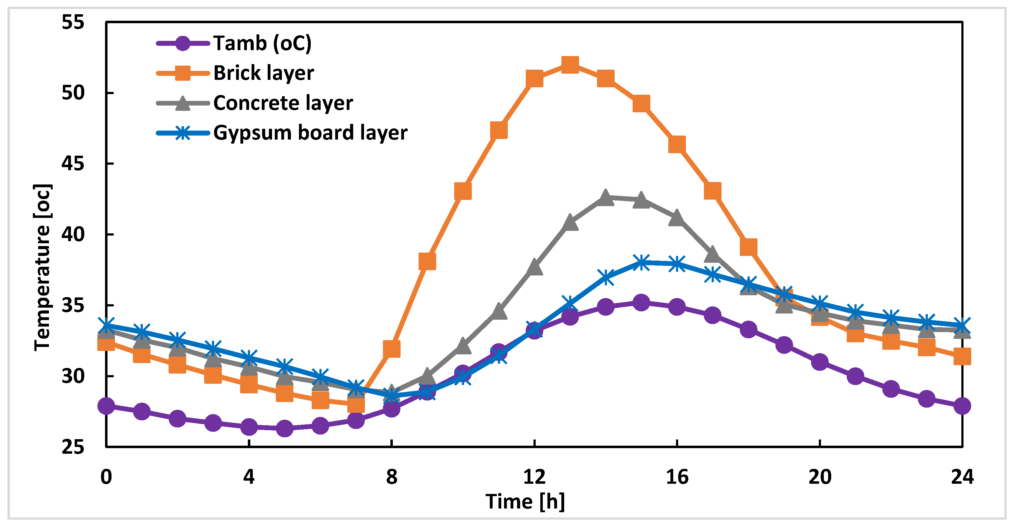
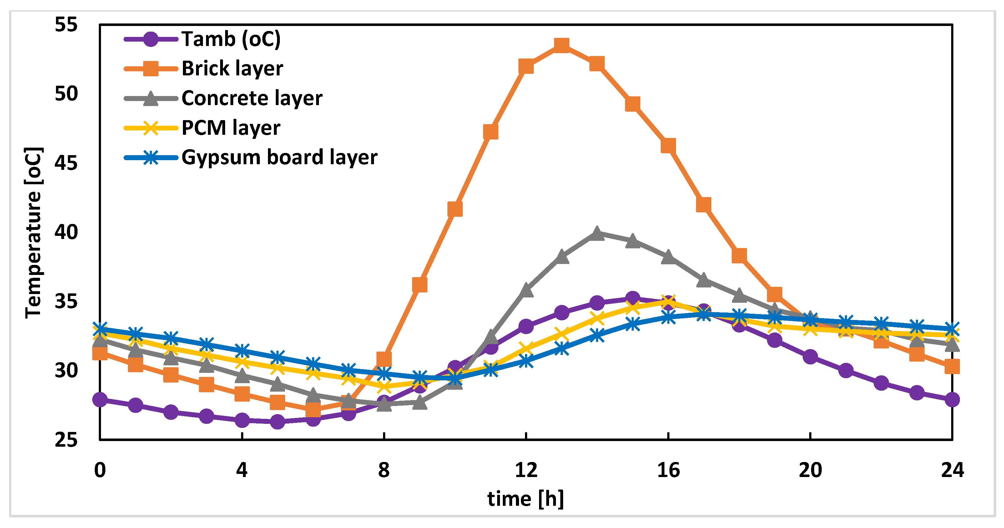
Figure 4 and
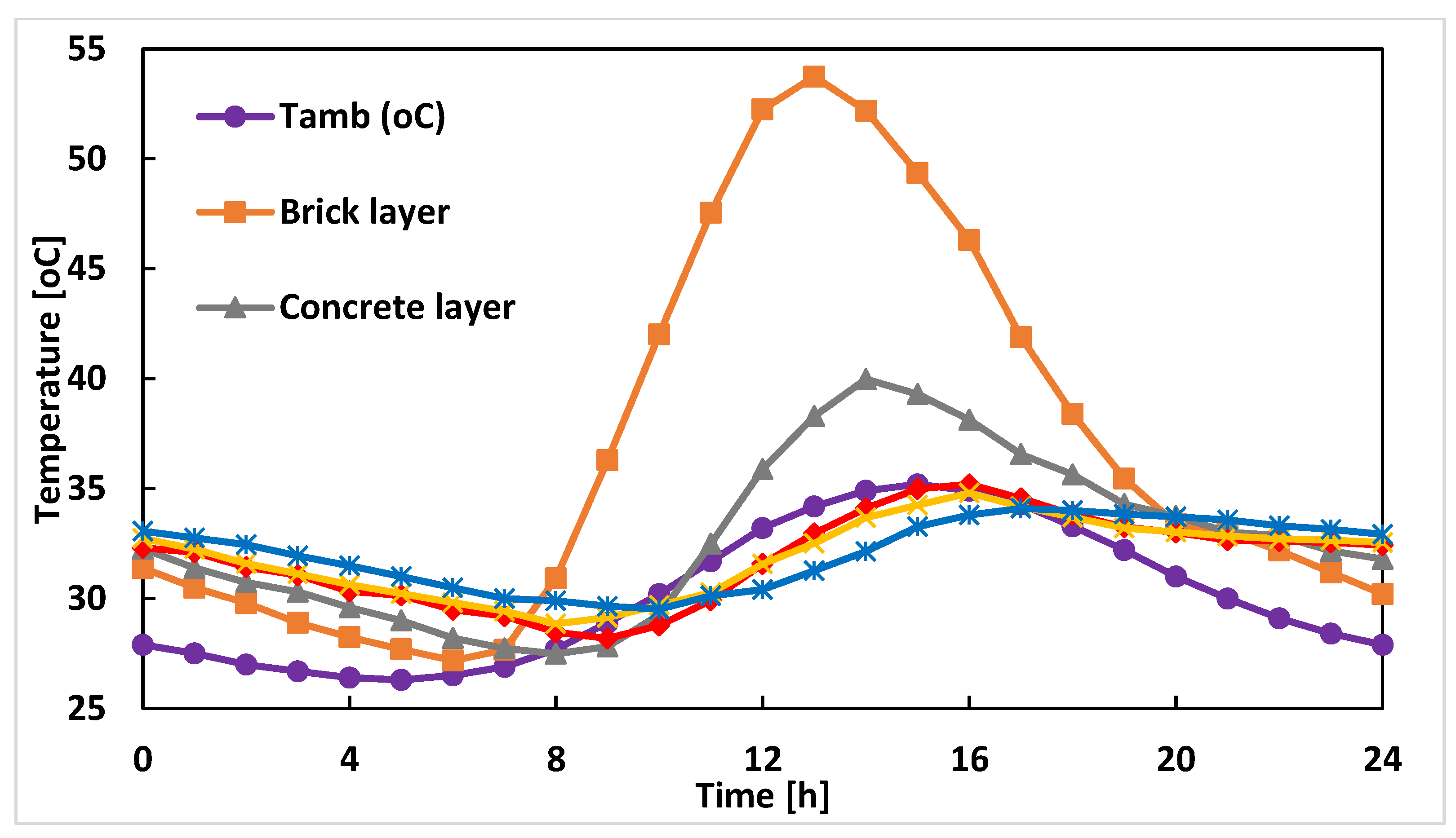
Figure 5, respectively, illustrate the average temperature variation in different structure layers of the PCM integrated roof and the roof without PCM for the month of July. It can be observed from these figures that due to the maximum solar radiation intensity at noon, the maximum temperature attained by the top layer (brick layer) in both the roofs is around 1:00 PM, but the maximum temperature attained by the PCM-integrated roof (about 53.4 °C) is marginally higher than that of the roof without a PCM layer. This effect is due to heat accumulation in the phase change material and its low conductivity in the liquid phase which results in the addition of heat to the top roof surface. It can also be observed from the figure that in the base layer (gypsum board) the maximum average temperature attained by the PCM-integrated roof is delayed by about 2 h compared to the roof without a PCM layer, which respectively occur at 5:00 PM and 3:00 PM. This delayed effect is due to absorption of heat energy by the PCM layer and thereafter its slow removal. The base layer of the PCM room has lesser average temperature and less temperature fluctuation (maximum average temperature of about 34 °C, 4 °C lesser than the roof without PCM layer) but it is not possible to maintain a constant comfortable temperature throughout the day, so the study was extended to PCM layers of different thickness.
5.2. Transient Temperature Analysis along Roof Thickness at Different Hours of the Day
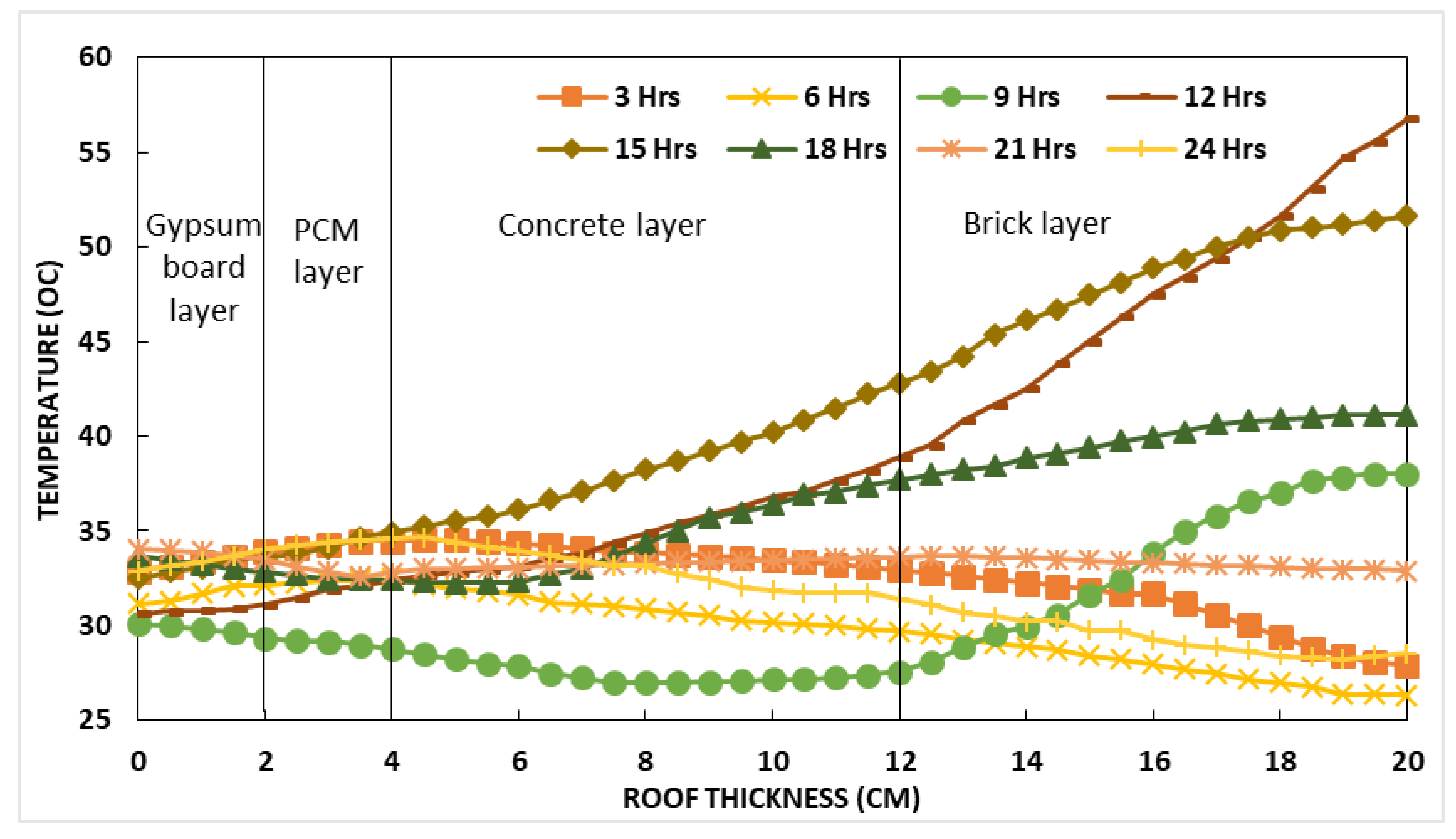
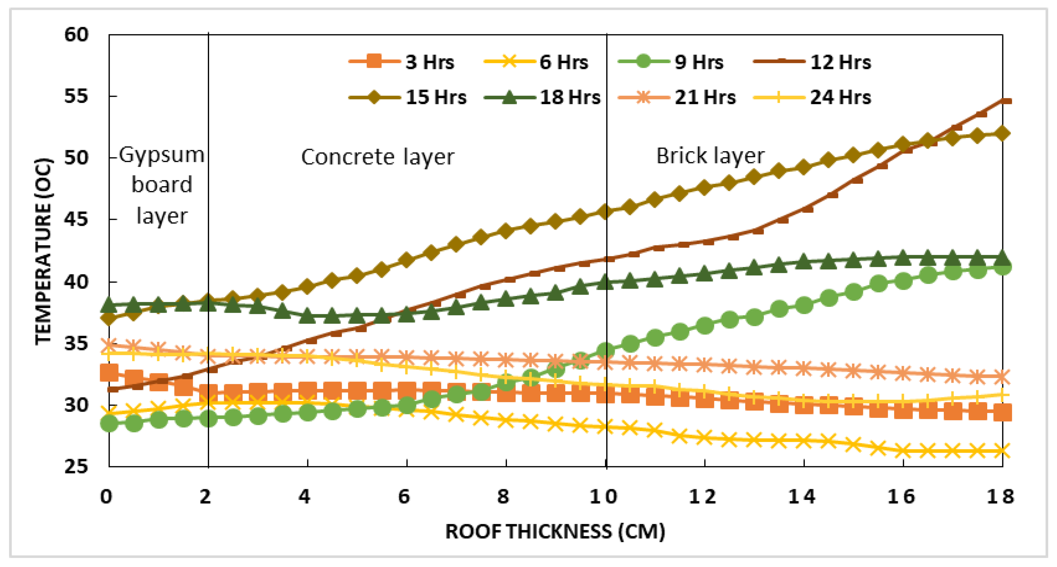
Temperature variation along roof thickness for the PCM-integrated roof (PCM 302K) and the roof without PCM at different hours of the day (3 h, 6 h, 9 h, 12 h, 15 h, 18 h, 21 h, and 24 h) has been shown in
Figure 6 and
Figure 7, respectively, for the month of July. It can be observed that the major temperature variation along the roof thickness occurs during the day hours when solar radiation is present and there are major fluctuations in ambient temperature. The brick layer and concrete layer, both of which are above the PCM layer, have wide temperature distributions throughout the day compared to the gypsum layer. This is due to heat absorption in the PCM layer and its slow removal which results in the addition of heat to the upper layers. In the PCM-integrated roof the average temperature in the base layer is always less than 34 °C, whereas in the roof without PCM the base layer temperature shows wide variation during different day hours. This is due to the fact that the PCM layer between the gypsum board and concrete has a high latent heat of fusion and is able to absorb cold energy during night hour and release the same during day hours. It was observed that an excessive rise of temperature at base layer was prevented by the PCM and thus restricts any heat gain through the roof inside the building envelope to maintain a lower temperature inside the building.
5.3. Effect of PCM Layer Thickness
The storage capacity of any given phase change material depends on the amount of PCM that can undergo a complete phase transition cycle during a complete day. The effective amount (thickness) of the PCM depends on the excitation amplitude of the PCM and excitation duration. The thickness of PCM suitable for maintaining thermal comfort and resulting in energy savings can be determined by correlation [
15,
24]. The effect of PCM layer thickness to maintain thermal comfort in the building room for the month of July has been investigated with different PCM layer thicknesses of 2, 4, 6 and 8 cm for PCM 302K having a transition temperature of 302 K as shown in
Figure 8. Other parameters of the roof structure layer have been left unchanged. With the increase in PCM layer thickness the peak average temperature in the base layer of the roof is reduced and delayed. The peak temperature in the base layer of the roof for a 2 cm PCM layer thickness occurs at 5:00 PM and is about 34.0 °C, for 4 cm PCM thickness at 6:00 PM and is about 33.5 °C, for 6 cm PCM thickness at 7:00 PM and is about 32.3 °C and for 8 cm PCM thickness at 8:00 PM and is about 31.3 °C. This delayed effect in peak temperature with PCM layer thickness is due to the absorption of more heat energy in the phase change material. Furthermore, it should be noted that there is optimum PCM thickness that can store the maximum heat energy for a day. Further increase in PCM layer thickness will result in higher investment cost but will not result in extra energy savings. From the figure, it can be observed that with the increase in thickness of PCM layer there is some reduction in temperature fluctuation but it is not possible to maintain a constant comfortable temperature. To achieve this, the study was further extended to PCMs with different phase change temperatures and heats of fusion.
5.4. Effect of Phase Transition Temperature and Heat of Fusion
The phase transition temperature and heat of fusion of the PCM determine the amount of heat absorbed/released in the PCM and play a significant role in the thermal performance of the building. It is important to note that PCMs with different phase transition temperature have different heats of fusion. To investigate the effect of phase transition temperature and heat of fusion three different phase change materials, PCM 302K, PCM 305K, and PCM 307K were considered and the simulation was carried out keeping all other parameters unchanged. The thermophysical properties of these PCMs are listed in
Table 1.
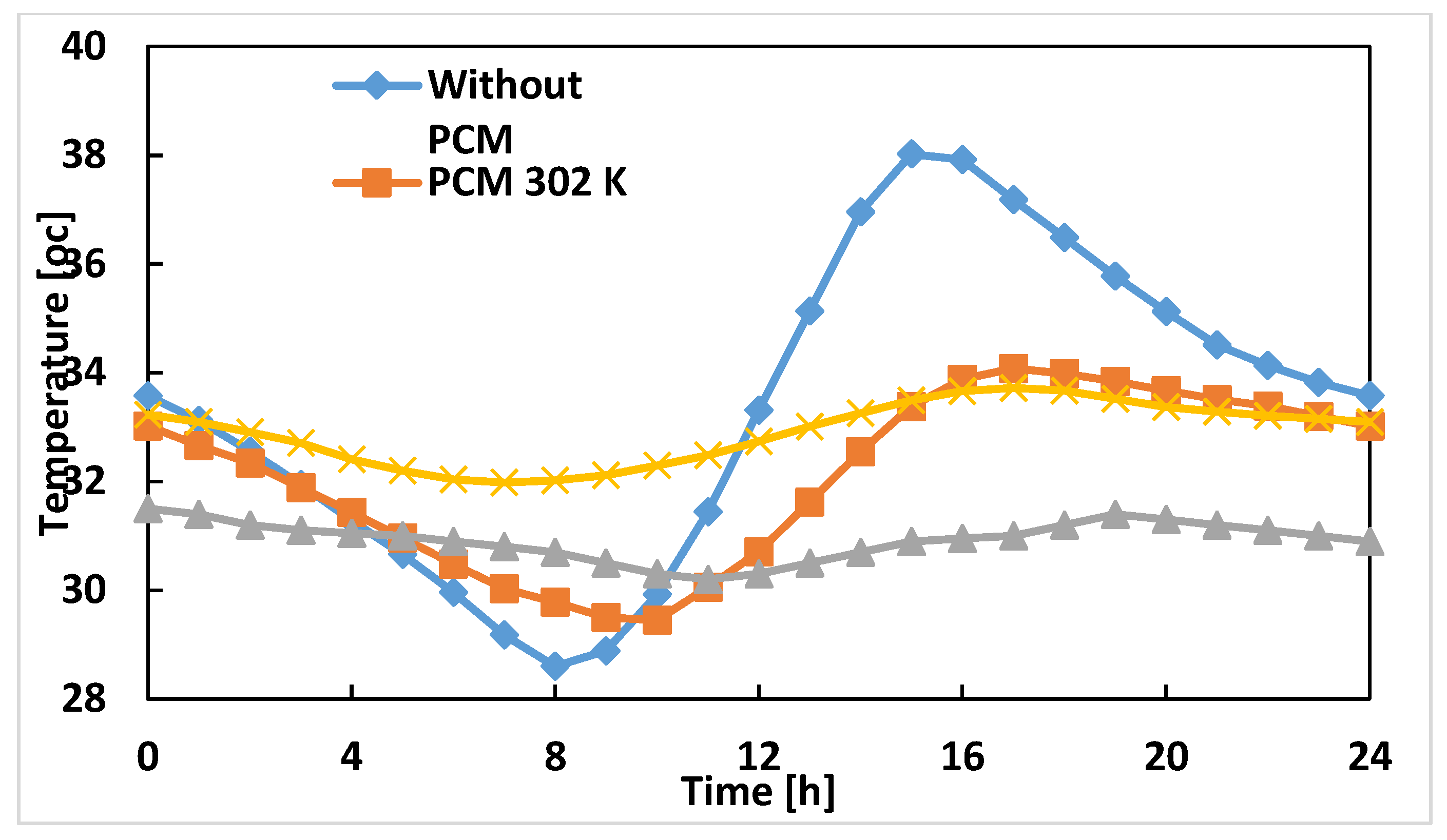
Figure 9 illustrates the average temperature in the base layer for different PCMs and a roof without PCM. The peak temperature in the base layer of the roof without PCM is about 38 °C at 3:00 PM, and with PCM 302K it is about 34 °C at 5:00 PM, with PCM 305K it is about 31.4 °C at 7:00 PM and with PCM 307K it is about 33.7 °C at 5:00 PM. It can be observed that with a PCM layer compared to the roof without PCM there is delayed effect in the peak temperature. This is due to heat absorbed in the PCM and its slow release. It can also be noted that the delayed effect with different phase transition temperatures is weak. During the day time when solar radiation is present, there is a good amount of heat reduction in the PCM-integrated roof with different transition temperatures and the temperature fluctuation is less, but it is not possible to have comfortable constant temperature throughout the day. To achieve this the study was further extended with the use of a multi-PCM layer in the building roof.
5.5. Effect of Multiple PCM Layers
It can be observed that integration of a single PCM layer in the building roof reduced some temperature variation in the base layer temperature but it is difficult to maintain a constant comfortable temperature throughout the day. Even by changing the thickness of the PCM and using different single PCMs having different melting temperatures and heats of fusion a comfortable temperature cannot be achieved. For a few month of the year a single PCM layer can even result in a negative thermal effect. Thus to have a constant comfortable temperature at the base layer of the building roof the study was extended with the addition of another PCM layer (PCM 305K) integrated between the existing PCM layer (PCM 302K) and the concrete layer (
Figure 10).
Figure 11 shows a temperature analysis of the different roof structure layers for the double PCM-integrated roof with both PCM 302K and 305K layers each having a thickness of 2 cm. It can be observed from
Figure 11 that the base layer in the double PCM roof attains a higher temperature than the single PCM layer roof (
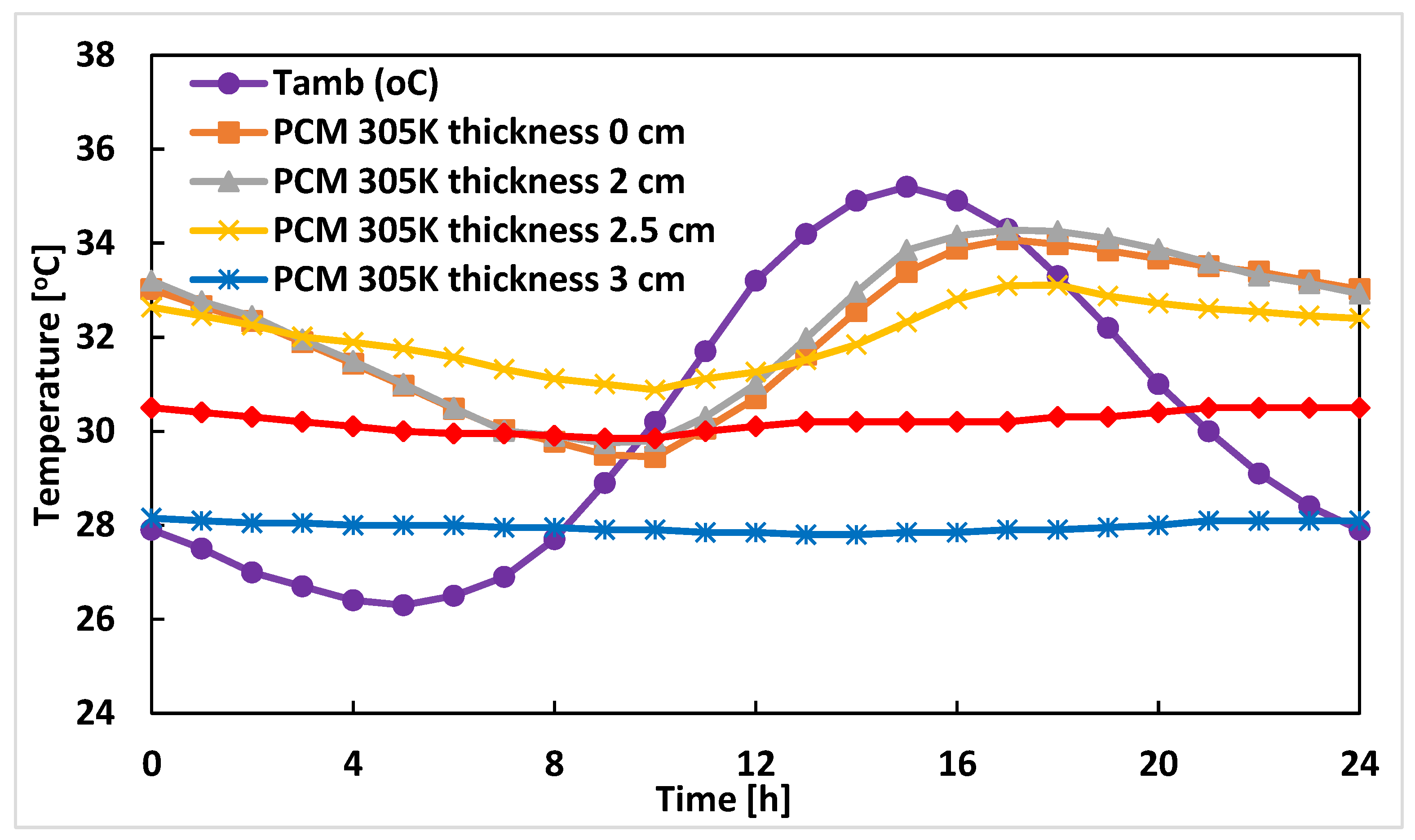
Figure 4). This is because the additional PCM layer remains in melting phase most of the time and complete solidification of PCM cannot be achieved. The simulation is further carried out with different PCM layer (PCM 305K) thicknesses of 2, 2.5, 3 and 3.5 cm keeping other parameters of the roof the same as in the single PCM (PCM 302K) roof of 2 cm thickness. It can be noticed that with the increase in thickness of the PCM 305K to 3 cm (
Figure 12), there is complete solidification and melting of the PCM which results in a comfortable base layer temperature of about 28 °C throughout the day. With further increase in the PCM layer thickness, there is not much change in the indoor temperature but that would add cost to the system. Thus with a double layer PCM of melting temperature 32 °C and 28 °C with respective thicknesses of 3 cm and 2 cm a comfortable constant temperature can be achieved in the building for the most part of the year.
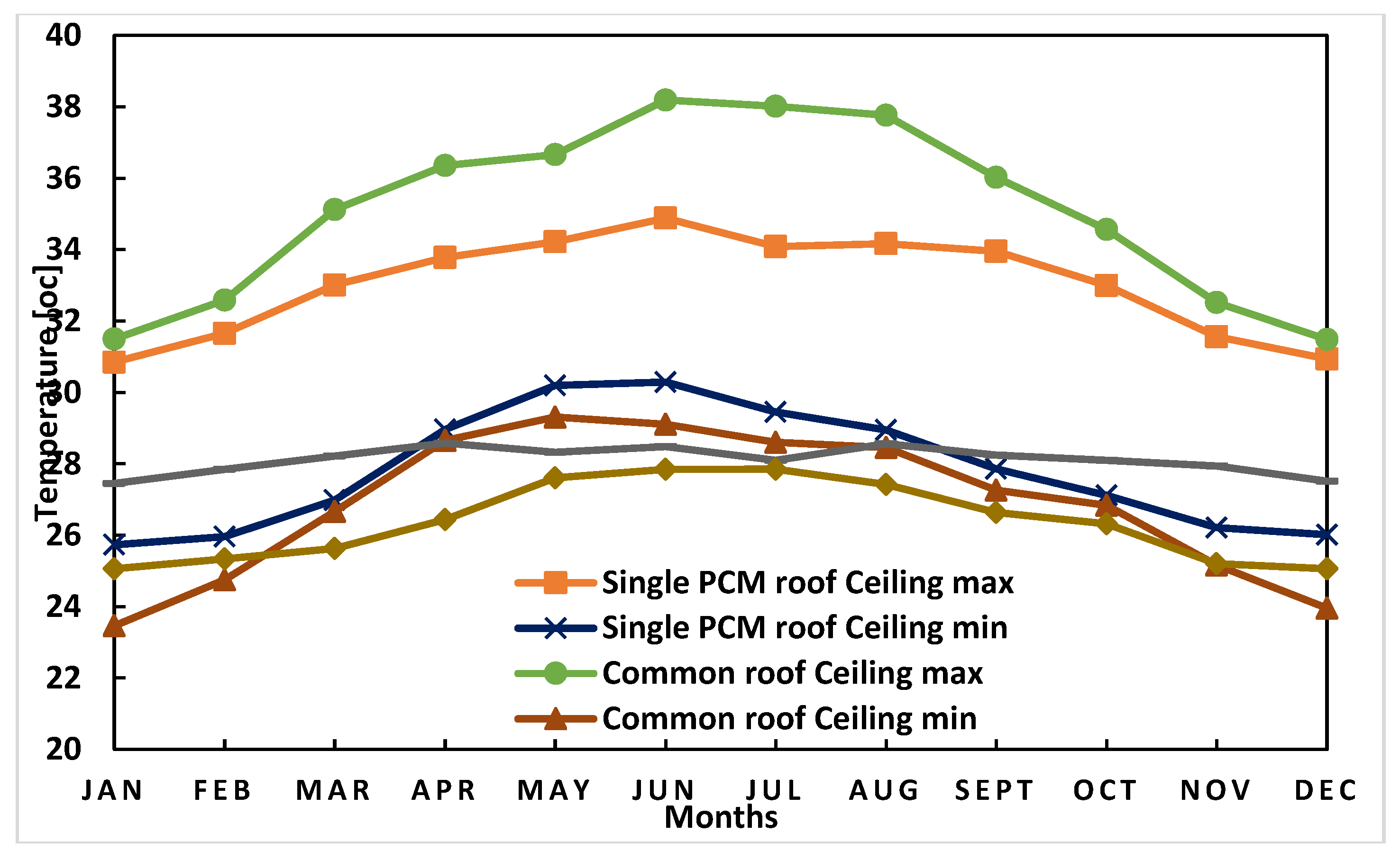
5.6 Monthly Performance Analysis
Figure 13 and
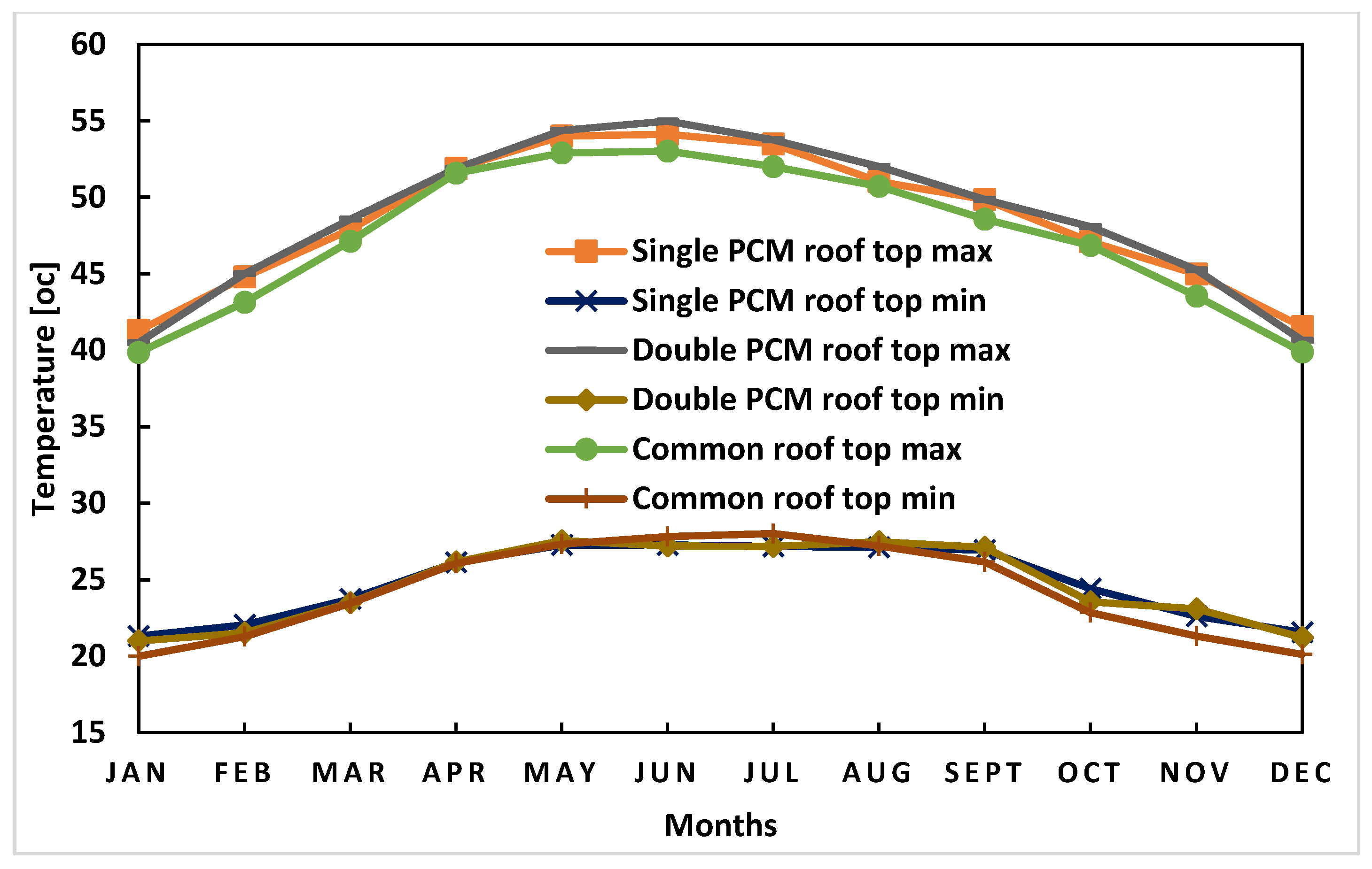
Figure 14 show one-year simulation results of the average maximum and minimum temperature of the roof top layer and the base layer, respectively, with a single PCM (PCM 302K)-integrated roof, double PCM-integrated roof (PCM 302K and 305K) and a roof without PCM. The maximum temperature of the top layer of the roof is between 12:00 Noon to 2:00 PM throughout the year due to the high intensity of solar radiation, whereas the minimum temperature is attained between 6:00 AM to 9:00 AM due to the cold energy released by the PCM layer. It can be observed that the maximum temperature in the top layer of the PCM-integrated roof is always marginally higher than the roof without PCM. This is because of the poor thermal conductivity of PCM in the liquid phase, which results in the slow release of thermal energy to the base layer and consequently heat get accumulated in the top surface. In the base layer, the maximum temperature attained in the PCM-integrated roof is between 4:00 to 6:00 PM and in the roof without PCM layer it is between 3:00 PM to 5:00 PM throughout the year. This delayed effect in the PCM layer is due to energy absorption and its release in the PCM layer.
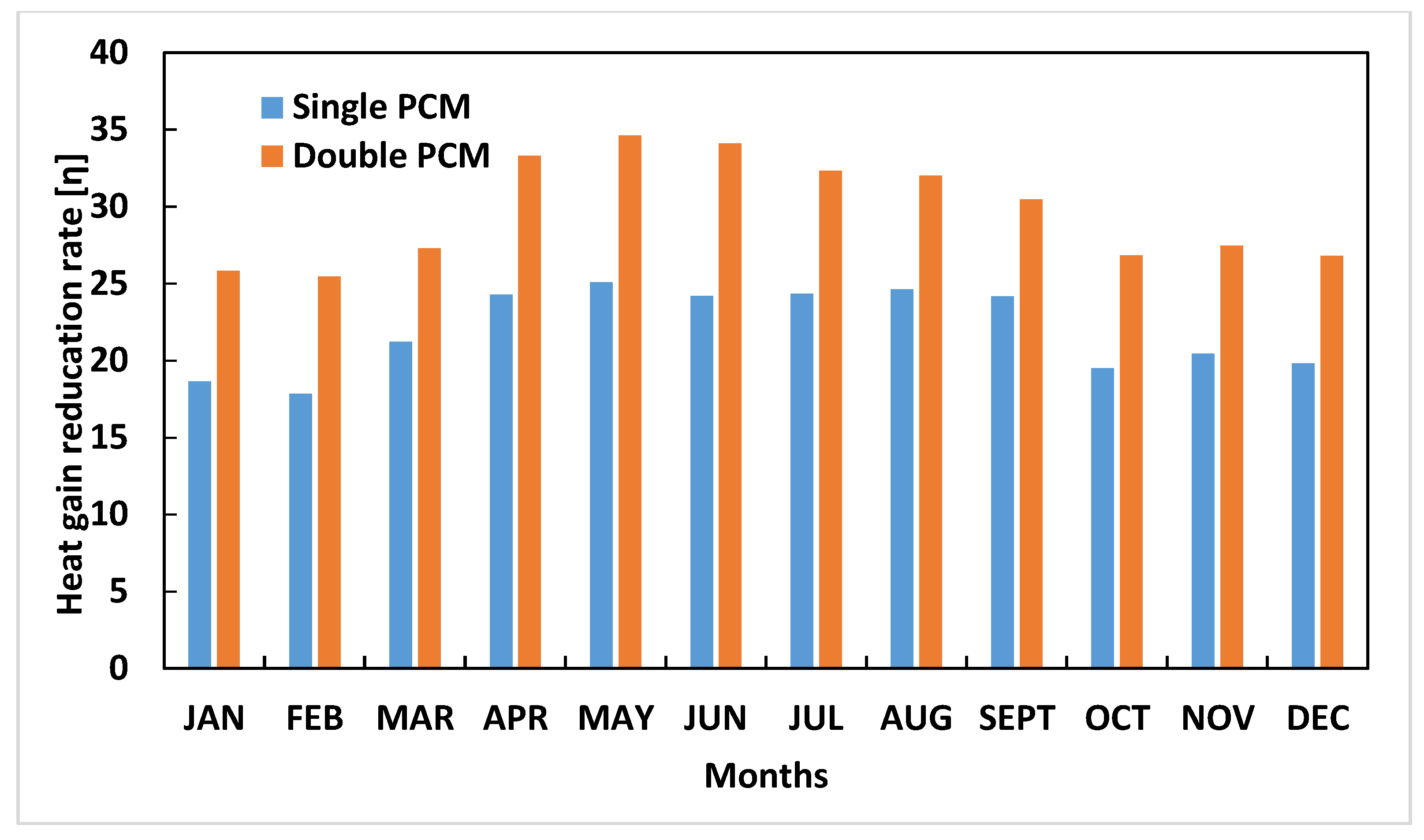
The effect of the PCM composite roof on decreasing the heating and cooling load in the building envelope is determined for different seasons throughout the year. The annual heat gain reduction rate (
) is due to the addition of PCM in the roof has been shown in
Figure 15. The heat reduction is the difference of total heat gain by the roof without PCM layer and the PCM-integrated roof. The heat gain reduction rate (
) is defined as:
where
QwithPCM and
QwithoutPCM are the total heat gain of the building with and without PCM layer in the building roof. It can be observed that due to the addition of a single PCM layer in the building roof there is heat gain reduction between 17 to 26 %, whereas addition of a double PCM layer results in a heat gain reduction rate between 25 to 35 %. This reduction in heat gain results in energy saving and leads to a comfortable temperature inside the building.


