Wire Structure Heat Exchangers—New Designs for Efficient Heat Transfer


Fraunhofer ISE, Fraunhofer Institute for Solar Energy Systems, Heidenhofstr. 2, 79110 Freiburg, Germany
*
Author to whom correspondence should be addressed.
Energies 2017, 10(9), 1341; https://doi.org/10.3390/en10091341
Submission received: 2 June 2017
/
Revised: 29 August 2017
/
Accepted: 30 August 2017
/
Published: 5 September 2017
(This article belongs to the Section I: Energy Fundamentals and Conversion)
Abstract
:Enhancing the heat transfer mechanism by increasing the heat exchanger surface area is a standard way to overcome low heat transfer on the gas side of heat exchangers. Different geometrical shapes, for example, plain, wavy, or interrupted fin geometries for plate-fin or tube-fin heat exchangers, are used for this task. Wire structures with dimensions in the submillimeter range are already used in regenerators for their heat capacity, but are rarely used in recuperators as heat transfer enhancers. New textile developments enable the fabrication of adapted structures with irregular grid sizes, and purpose-built for heat exchanger application. These wire structures allow for enlarging the heat transfer surface area, decreasing material utilization, and enabling flexibility of different geometrical dimensions. Possibilities for manufacturing and design selection are studied in the project, EffiMet, and thereafter at Fraunhofer ISE for the implementation of highly efficient heat exchanger geometries based on wire structures.

1. Introduction
In recent years, the technical textile industry has been developing innovative methods to process metal materials in specific arrangements. These technical textiles promise to fulfill the requirements of highly efficient heat exchangers, such as high heat transfer surface areas, low material utilization, and flexible geometries.
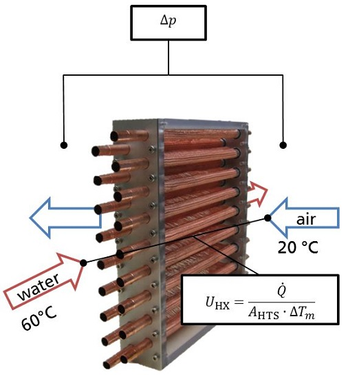
The focus of this study is on gas-to-liquid heat exchangers. The wire diameter of the manufactured structures is in the submillimeter range. The lengths of the wires between two faces, separating the gas side from the liquid side, are in the lower centimeter range. The heat transfer enhancement is realized on the gas side, as heat transfer is limited there (primarily due to the low thermal conductivity of gas). Similar to heat transfer enhancement with ordinary fins, gas flows around the additional structure. Assuming that the gas is hotter than the liquid, heat is transferred from the gas to the wire by convection, through the wire and a fluid-separating wall by conduction, and finally to the liquid, again by convection (see design in Figure 1).
The heat transfer coefficient on the wires increases with decreasing wire diameter, due to a reduction of the thermal boundary layer thickness and, therefore, larger temperature gradients in the gas flow (if the velocity is kept constant). This results in a heat transfer coefficient of approximately 500 W/m2K for the air flow around a single wire of 0.1 mm in diameter, at an incoming air temperature of 25 °C and a velocity of 2 m/s. In addition, the material utilization for manufacturing wires is less than that for metal sheets with the same heat transfer surface. Assuming that the diameter of a wire is the same as the thickness of a metal sheet, the mass-specific surface area is twice that for the metal sheet. These positive effects have to outweigh possible drawbacks, which are related to high pressure drop due to very dense wire structures and low volume-specific heat transfer surfaces for very open wire structures.
In this study, design concepts are developed that are technically feasible and for which the benefits of a high heat transfer surface and low material utilization prevail. The concepts are examined by manufacturing test pieces and measuring the heat transfer and pressure drop at a test rig at Fraunhofer ISE, as well as by simulating the velocity and temperature fields around the structure with the CFD software Comsol Multiphysics®. The study is based on the results of the EffiMet Project [1].
For heat transfer enhancement in heat exchangers with low convective heat transport on the gas side, a variety of different design ideas are given in the literature and on the market. Very fine structures with high heat transfer surface area can be realized by using metallic foams as a heat transfer structure. However, these structures generally have very high pressure drops due to their undirected microgeometry [2,3,4]. Likewise, heat flux through undirected microgeometry is inhibited.
Heat flux through a structure should best be oriented normal to the primary surface separating the fluid from the heat source or sink (tubes). This can, on the one hand, be achieved by a pin-fin structure with anisotropic thermal conductivity, although its manufacture is costly [5,6]. On the other hand, wire structures based on weaving or knitting technology can be oriented similarly, with the benefit of highly developed manufacturing processes. Currently, wire structures are used as regenerators due to their high surface area density, if arranged appropriately.
Metallic woven-wire mesh structures [7,8,9] and screen-fin structures [10] are contacted to a flat primary surface. One market-available air-to-air heat exchanger with a separating plastic wall is manufactured by Vision4Energy [11], and an evaluation of its performance is done numerically [12]. Further numerical studies of pins with different cross-sectional shapes and a comparison of the thermal and fluid dynamic performances with louvered fins are given in [13]. From this performance comparison, it was found that the pin fin heat exchanger is able to perform in the same way as a louvered fin heat exchanger, but with 22% less volume. The author stated that, to his knowledge, there is no known manufacturer of these pin fin heat exchangers.
Wire-on-tube type heat exchangers [14,15] have to enable contact on rounded surfaces. Some design ideas are specified in patents [16,17]. The wire diameter in both types of heat exchanger primarily ranges from 100 μm to 1 mm.
However, the woven or knitted wire structures described in the literature are predominantly limited to mesh, with additional wires only weakly supporting heat transfer. These impeding wires, which still create a pressure drop, are not directly contacting the primary surface but instead are oriented in parallel to the tubes. Thus, heat transfer has to take place along multiple wires, with thermal contact resistance between each of them.
2. Results
2.1. Manufacture of Samples
Compact heat exchangers with high volume-specific heat transfer surface area are often manufactured as plate-fin or tube-fin heat exchangers. The volume-specific heat transfer surface is usually in the range of 700–2000 m2/m3, in extreme cases reaching up to 5000 m2/m3 [18].
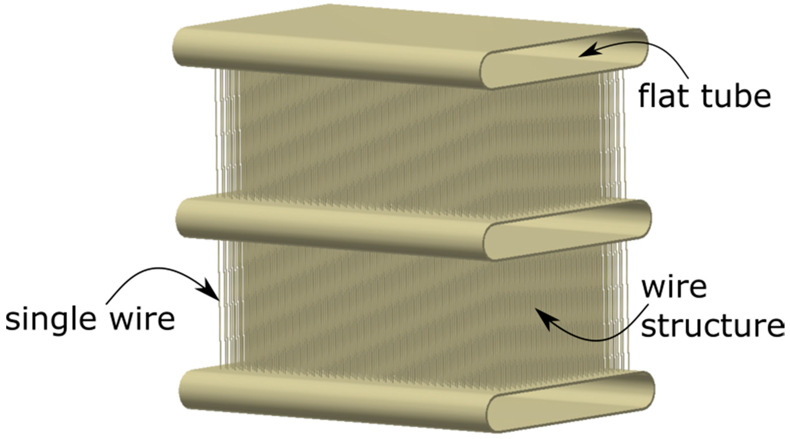
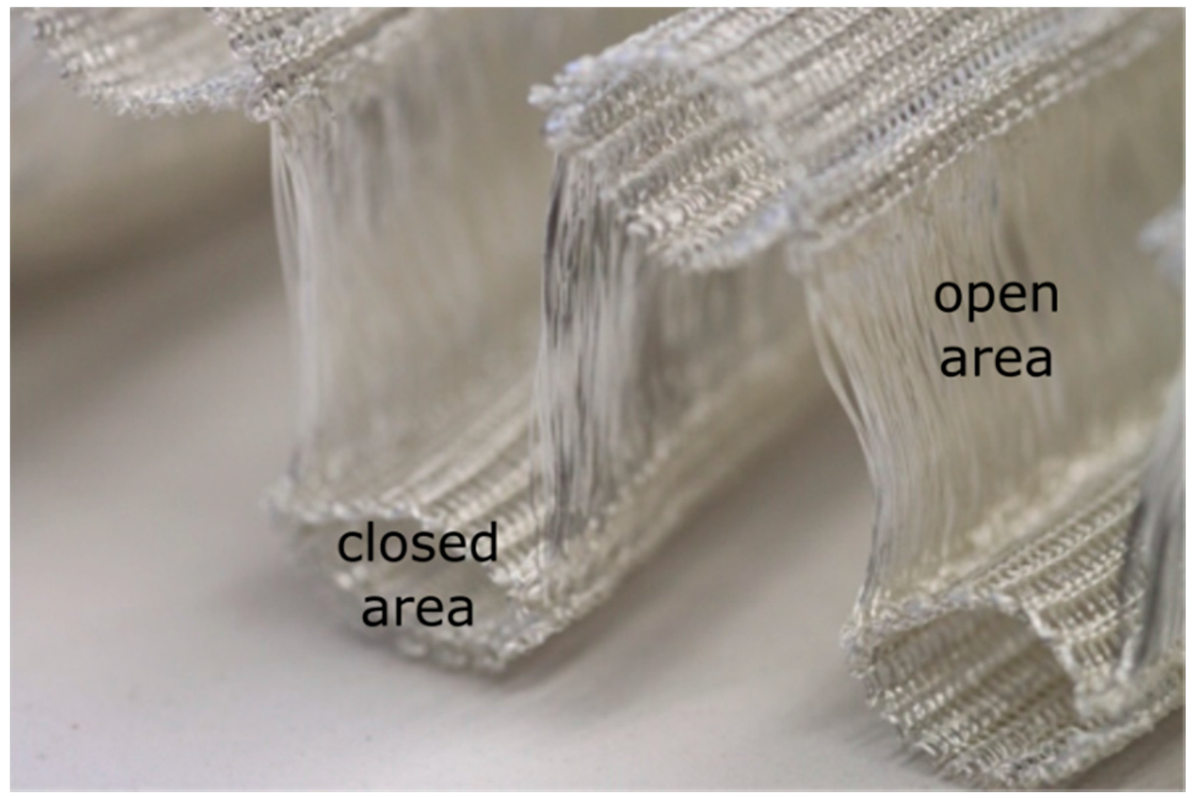
Wire structure design concepts have been developed for both the plate-fin and the tube-fin heat exchanger. An advanced manufacturing process is used by VISIOTEX GmbH (Wismar, Germany) to fabricate complex 3-dimensional (3D) wire structures that serve as gas-side heat exchanger surface. A combination of knitting and weaving takes place to form the final product with dense domains and coarse domains (see Figure 2). The coarse domains serve as heat exchanger surface enhancement where gas flows around the wires. The dense domains are soldered to a primary structure (tubes), allowing for good thermal contact.
For the manufacturing of wire structures, standard textile machinery has been adopted by VISIOTEX GmbH for metal wire handling, including specially coated knitting needles, wire guidance, and lubrication. Thermal contact is ensured by galvanically applied solder on both the wire structure and the tubes. To ensure even and reliable galvanization, Hattler GmbH (Villingen-Schwenningen, Germany) developed an automatic electroplating line dedicated to complex wire structures, including cleaning, electroplating, and electroless deposition of different metals. After coating, the tubes and wire structures are mounted in custom-made jigs and heat treated by Fraunhofer IFAM (Dresden, Germany) [1].
Various small-scale samples of 10 mm × 100 mm × 30 mm in dimension have been manufactured and tested for pressure drop and heat transfer at Fraunhofer IFAM. The results were used to develop the heat exchanger samples, with dimensions of 200 mm × 230 mm × 30 mm, presented in this paper. These heat exchangers are based on a fin-and-tube design with smooth copper tubes. Instead of fins, the wire structure is soldered in the space between the tubes. Water is applied inside the tubes, and air is applied to the outside.
The aim of the sample manufacturing is to demonstrate the feasibility of the manufacturing process at a prototype stage and to illustrate possible geometries. Given the early stage of development, it might not be expected to yield a performance comparable to state-of-the-art heat exchangers (HX). The optimization potential for these novel HX geometries is explored by numerical simulation (see Section 2.2).
2.1.1. The Round Tube Wire Heat Exchanger
Figure 3 shows the round tube wire heat exchanger (RT WHX). Copper tubes () are inserted into a 3D knitted copper wire structure (see Figure 2) with a wire diameter of 0.1 mm, soldered in a jig and mounted in polymethylmethacrylat housing, allowing for a tight air-side connection and visual inspection. To allow for parallel flow on the water side, headers with a large cross-section () are mounted to the tube ends. The oversized header cross-section ensures low pressure drop in the header and thus equal water distribution among the tubes when connected in a U-configuration. This is to allow easy data evaluation and is probably not appropriate for any later application. The geometrical specifications of the RT WHX are given in Table 1.
2.1.2. The Flat Tube Wire Heat Exchanger
The flat tube wire heat exchanger (FT WHX) shown in Figure 4 is based on the concept of a standard plate-fin heat exchanger. Flat copper tubes (Eugen Geyer GmbH, Königsbach-Stein, Germany) are first brazed into headers. After electroplating, the folded wire structure (Figure 4, left) is inserted into the frame and heat-treated for soldering. The wire structure is a flat-knitted fabric and consists of several narrow stitches followed by one wide stitch. Air will flow through the more open area of the wide stitch. The wire material is copper. The structure is folded at the edges between the narrow and wide sections so that the narrow region can be connected to the tubes. The droplets on the headers result from excess solder on the surface areas not in contact with the wire structure.
The utilization of additional polytetrafluoroethylene counterparts to keep the folded structure in its form before soldering has been tested. However, it was found that the structure is self-supporting, so that the counterparts could be omitted (see Figure 4 middle). For the same reason as for the tube-fin test piece, the cross-section of the headers is large in comparison to the flat tube cross-section. The geometrical specifications of the FT WHX are also given in Table 1.
2.2. Methods of Determining the Performance
2.2.1. Experimental Setup
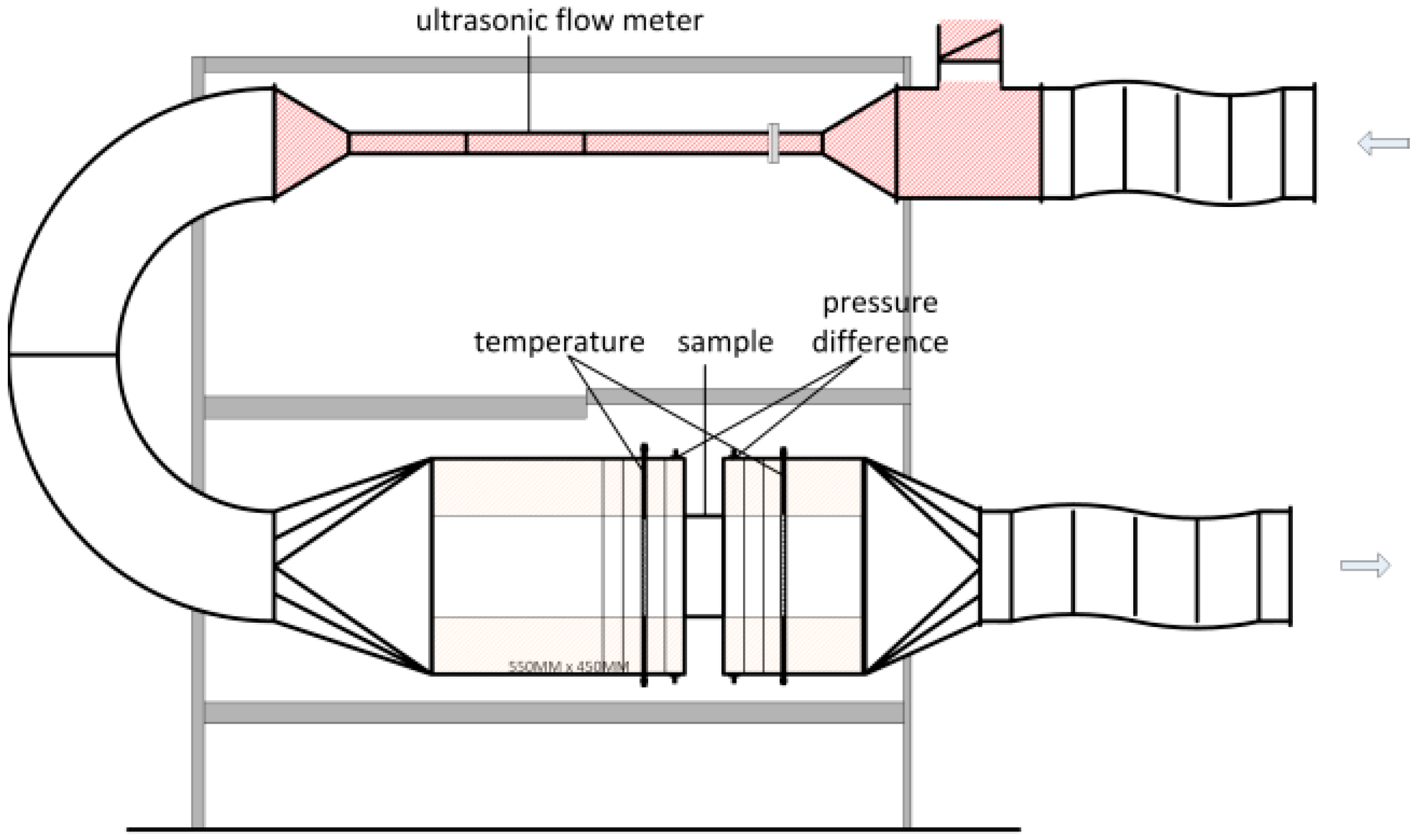
The test samples are characterized for heat transfer and fluid dynamics at a test rig at Fraunhofer ISE. Air and water are used for characterizing the gas-to-liquid heat exchangers. The test rig is described in [19] and has been adapted. In front of the test section containing the sample (see Figure 5), a flow conditioning section is installed on the air side (not shown). It comprises a chiller, an electric heater, a humidifier, a controllable fan, and the respective sensors for air temperature, humidity, and volume flow (orifice plate). It can deliver temperatures in the range of 5–40 °C and volume flow rates of 150–1000 m3/h.
In order to be able to measure heat exchangers at lower air volume flows, a bypass valve is installed in the upper part of the setup, with an ultrasonic flow meter in a DN50 duct section (highlighted in Figure 5). This way, air volume flows as low as 10 m3/h can be measured. For volume flows of 150 m3/h and above, this section is replaced by a straight DN280 tube. Following the bend (DN280), there is a 510-mm straight, rectangular channel of 185 mm × 231 mm. In the test section, fast-reacting thin-film Pt100 temperature sensors are used (calibrated to a standard uncertainty of 0.05 K). Four sensors are installed at the inlet channel, followed by two metal screens, which ensure a uniform velocity profile. In the outlet channel, 12 sensors record the temperature. All sensors are installed in the center of squares of equal area adopted from DIN EN 306. The pressure drop across the sample is measured with two differential pressure transmitters (PU/PI; halstrup-walcher GmbH, Kirchzarten, Germany) with a measuring range of 0–50 Pa (for good accuracy at low pressure drops; standard uncertainty: 0.1 Pa) and 0–250 Pa (for high pressure drops; standard uncertainty: 1 Pa). The entire testing section is leakage tested and thermally insulated.
On the water side, the temperature and volume flow rate can be controlled by a chiller/heater (Unichiller 017Tw-H, Huber Kältemaschinenbau AG, Offenburg, Germany) and measured with Pt100 resistance temperature sensors (Omnigrad T TST310, Endress+Hauser, Reinach, Switzerland; calibrated to a standard uncertainty of 0.05 K) and an electromagnetic flow sensor (Optiflux 1000, Krohne, Duisburg, Germany; standard uncertainty: 0.4% of the measured value). Pressure drop is measured via a differential pressure transmitter (idm331, 0–0.6 bar; ICS Schneider Messtechnik GmbH, Hohen Neuendorf, Germany; standard uncertainty: 3 mbar).
During measurements, the inlet air temperature is fixed at ambient temperature in order to avoid losses, while the water enters the heat exchanger at 60 °C. The water flow rate is set to ~1 m3/h to avoid heat transfer limitation on the water side; therefore, the change in water temperature across the heat exchanger is very small (<1 K). For the characterization of the heat exchangers, the air volume flow is increased stepwise from 30 to 800 m3/h. The heat exchanged is then determined through the air-side energy balance.
This information yields the pressure drop the total heat transfer rate in the heat exchanger
and, thus, the overall heat transfer
Equations (1) and (2) are based on the mass flow rate , the specific heat , the temperature difference , and the true (or effective) mean temperature difference, also referred to as the mean temperature driving potential . For a cross-flow heat exchanger with known inlet and outlet temperatures of the two fluids, the mean temperature driving potential is equal to the product of the log-mean temperature difference and a correction factor [18], Chapter 3.7:
The product of the heat transfer surface area on the air side (including the wire structure and the outer tube wall) and the overall heat transfer coefficient can be separated into its factors if the heat transfer surface area is known. However, for some heat exchanger designs, can only be approximated as the fins/wires might touch each other or the soldering joints might be unspecified. In the Appendix A, the heat transfer surface area density of all heat exchangers is approximated in Table A2. In the following analysis, the product is used with no need to separate the factors. For the experiment, the correction factor , defined in [18], Chapter 3.7.2, was used to determine the correct mean temperature difference for a cross-flow heat exchanger.
2.2.2. CFD Simulation
There are no correlations for heat transfer and pressure drop vs. air velocity known from the literature, for the specific geometries used in the design concepts. Thus, detailed CFD simulations are necessary to obtain this information. Simulations allow, on the one hand, comparison of the results to those from the measurements; on the other hand, a variety of geometries can be compared without the need to manufacture them.
Fluid flow and heat transfer are simulated by using the finite-element method (FEM), implemented in Comsol Multiphysics® (Göttingen, Germany; version 5.2). Boundary conditions for temperature, pressure, and velocity were chosen to ensure a steady-state laminar flow, and are shown for the flat tube wire heat exchanger in Figure 6. The simplified continuity equation, the Navier–Stokes equation, and the equation for energy conservation describe the system on the air side, whereas the equation for energy conservation describes the solid domain.
The water side is not simulated. Instead, a fixed temperature is set at the inner tube wall as a boundary condition. Firstly, the mass flow on the water side in the experiment is high enough so that the temperature undergoes only a slight reduction. Secondly, the simulated characteristic element is small in the flow direction of water; temperature differences on the water side would not be distinct. The sections between the solid and the air domain are set to a no-slip condition. At the air inlet section, the velocity is fixed. At the air outlet section, the absolute pressure is fixed. All other boundaries are symmetric. Contact resistance between wires and tubes is disregarded and not implemented. The velocity streamlines and the temperature distribution for one of the geometries are depicted in Figure 7. For a later simulation, an inline wire arrangement is used. The lateral wire pitch is equal to 0.45 mm, the transversal wire pitch is bounded by 0.7 mm 0.9 mm, and the wire diameter is equal to 0.1 mm. For the round tube wire heat exchanger, similar 3D simulations of fluid flow and heat transfer were performed with Comsol Multiphysics® for potential analysis.
The numerical solutions were checked regularly for mesh-independence. For the 3D FT WHX Sim3 geometry, a mesh-independent solution could be found with 5 million tetrahedral elements (relative error between the Richardson extrapolate [20] and the simulation result for the pressure drop and heat transfer coefficient is lower than 2%). The round tube design is computationally less costly, with 3.5 million tetrahedral elements.
2.2.3. Performance Evaluation Criteria
When a wire structure is contacted to tubes, the same procedure as for conventional fins can be applied to estimate the convective heat transfer coefficient. In this case, we refer to an effective heat transfer coefficient . It includes the convective heat transfer from the air to the wire structure, the heat conduction through the wires and the tube wall towards the inner fluid tube wall, and a possible contact resistance between wires and tube, but not the convective heat transfer inside the tubes [3,19]. The effective heat transfer coefficient refers to the same heat transfer surface area as described in Equation (2).
For the simulation, the effective heat transfer coefficient
can be directly evaluated from the total heat flow and the mean temperature difference
For the experiments, the water side wall temperature is not known, so has to be determined indirectly from the overall heat transfer (cf. Equation (2)). The latter is the result of a series connection of and the water side convective heat transfer . Thus,
The heat transfer coefficient on the water side is calculated based on correlations for the respective geometry and flow conditions (turbulent, laminar, transition) available in the literature (cf. [21]). For example, the heat transfer coefficient for the flat tube in Reference [2] (see geometry in Table A1) ranges from 2000 W/m2K for a laminar flow to 17000 W/m2K for a turbulent flow at a Reynolds number of 8000 (at 60 °C) [18], Table 7.3 and Equation (7.79). The heat transfer surface area on the water side is the inner tube surface area given by the geometry. In Reference [2], is smaller than by a factor of 100. For further evaluation, the product of and will be used in order to avoid any confusion related to the determination of .
The pressure drop is calculated by taking the difference of the air inlet pressure and the air outlet pressure. The dissipated power is used for further evaluation and can be approximated by
with the air inlet volume flow rate .
The effective heat transfer and the dissipated power can be related to each other in order to compare benefit to cost. The benefits of “heat transfer” can be accompanied by additional “costs”. Together with the dissipated energy these might be:
- the dissipated power on the air side , which is proportional to the power of the fans in W;
- the mass of the material used for the wire or fin structure (excluding tubes, solder material, and header) in kg;
- the volume available for heat transfer enhancement in m3 (including tube volume, excluding header).
Other parameters for material utilization, for example, the mass of fins including the tubes, are applicable as well. Considering the approach of efficiency = benefit/costs, three key figures can be defined as shown in Table 2.
The performance evaluation in this study will be based on the key dimensional figures in Table 2. A depiction of non-dimensional parameters such as the Nusselt number () for heat transfer, the friction factor () for pressure drop, and the Reynolds number () for the flow rate would be standard; however, they do not provide an adequate tool for comparing the performances of different heat transfer surfaces [13].
Comparison of the different heat exchanger types based on the key figures in Table 2 shows the strengths and weaknesses of the different types. For example, a low heat transfer surface area density :
yields low volume efficiency as long as the effective heat transfer coefficient attains normal values; however, the energetic and mass efficiencies might not be affected by low values of .
2.2.4. Reference Heat Exchangers and Potential Analysis
The performances of the wire heat exchangers will be compared to those of state-of-the-art heat exchangers. Therefore, heat transfer behavior and pressure drop have been measured for an aluminum flat tube heat exchanger with louvered fins (FT Ref1), as can be seen in Figure 8 (left). The transversal tube distance for this heat exchanger is equal to 9.9 mm. Furthermore, correlations from the literature [22] for louvered fins are used to determine the performance of a second flat tube heat exchanger (FT Ref2) made of copper with equal to 10.2 mm. For the simulated wire heat exchanger, likewise equals 10.2 mm. Pressure drop information for FT Ref2 is given by the manufacturer.
For a comparison of the performance of the round tube wire heat exchanger (RT WHX) and the round tube heat exchanger with wavy fins (RT Ref; see Figure 8, right), the heat exchanger with wavy fins was simulated in the software tool CoilDesigner® [23]. In the simulation, the transversal tube distance is equal to 23 mm. The performance evaluation criteria in Table 2 can be calculated from the results of these simulations and measurements. The geometrical dimensions for all three reference heat exchangers are given in the Appendix A.
Both wire heat exchangers were primarily designed in order to demonstrate their manufacture; their performance can be increased if the corresponding geometrical design is adapted to operating conditions. Therefore, a potential analysis of an improved geometry is performed using the CFD model described above. The wire pitch in flow direction is varied. Details are given in the Appendix A. A selection of geometries is used to depict the range of possible performances.
2.3. Evaluation
The results of the experiments, simulations, and correlations from the literature [22] for thermal and hydraulic performances are compared in Figure 9 and Figure 10.
The uncertainty of experimental results is assessed based on measurement uncertainties using the Gaussian uncertainty propagation rule [24]. The level of confidence is expressed in terms of an expanded uncertainty interval. The expanded uncertainty is obtained by multiplying the combined standard uncertainty by a coverage factor of 2. Assuming that the measurement data is normally distributed, 95% of the data lies in this interval. The major cause of the uncertainty is due to the definition of heat loss to the ambient.
For both the simulated and the measured round tube wire heat exchanger, the energetic efficiency is lower than for the reference RT Ref (see Figure 9a). An increase in air velocity results, for all heat exchangers, in a decrease in energetic efficiency. This is due to the fact that the overall heat transfer does not increase as fast as the dissipated power with increasing air velocity.
However, the mass efficiency of the round tube wire heat exchangers is higher than for the reference (see Figure 9b). This results primarily from the high surface-to-mass ratio of the wires and, in addition, from the high heat transfer coefficient on these surfaces. After visual inspection, it is assumed that the measured wire heat exchangers lack a well-soldered contact between the wires and the round tubes. Hence, the resulting thermal contact resistance might limit the heat transfer. The difference between the simulation (RT WHX Sim1) and the measurement (RT WHX) supports this assumption. In the simulation, a perfect contact is assumed. It was possible to reproduce the experimental results by adding a contact resistance in the simulation. For simulation, the same mass of the heat exchangers was used as for the measurements. All three mass efficiency curves increase with increasing air velocity. The shape of the curves corresponds to the shape of the effective heat transfer coefficient (or ) with air velocity cf. [25], as the mass and the heat transfer surface are constant for each heat exchanger.
Lastly, the volume efficiency is depicted in Figure 9c. The difference between the measurement and the simulation is the same as explained for the mass efficiency, as the construction volume of the measured sample was adopted for simulation. However, the reference is in a similar range of efficiency as the simulation, as the reference is manufactured in a very compact design with 10 fins per inch (i.e., 2.5-mm spacing) whereas the RT WHX has large void domains where no heat transfer takes place. The shapes of the curves are equal to those of the mass efficiency curves, although they are normalized based on the heat exchanger construction volume instead of its mass.
Neither the measured nor the simulated round tube wire heat exchanger show benefits in energetic or volume efficiency. Thus, a more detailed analysis on performance enhancement is not carried out in this study, instead the focus is placed on the flat tube wire heat exchangers.
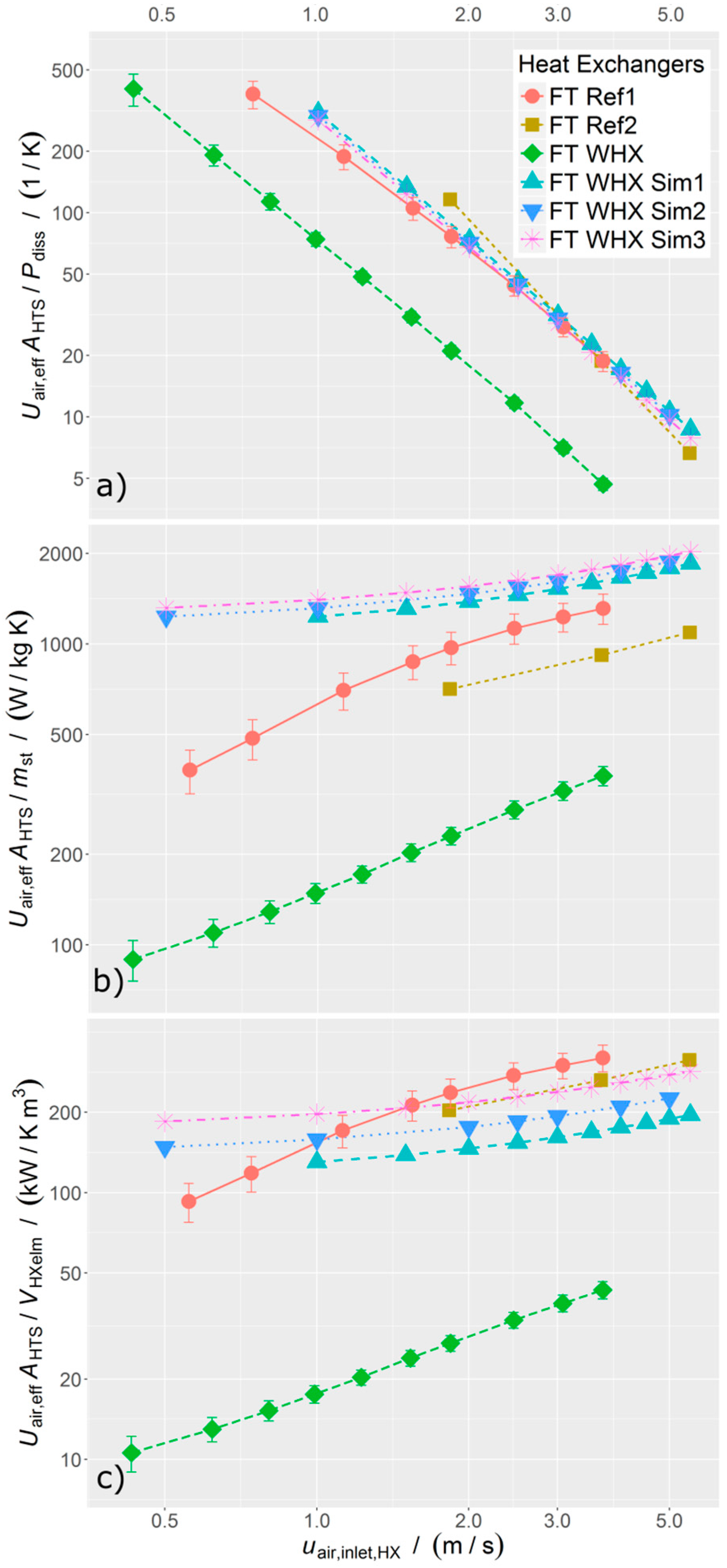
For the flat tube heat exchanger, an extended performance analysis was performed. In Figure 10a, the energetic efficiency is plotted versus the heat exchanger inlet velocity. The measured wire heat exchanger sample (FT WHX) shows energetic efficiency values of less than 30% compared to the reference heat exchangers (FT Ref). Firstly, this is due to a lower heat transfer area, as the wire pitch (two times the distance between the rows of wire perpendicular to the air flow) is 10.6 mm and therefore more than five times larger than for FT Ref1. Secondly, the flat tubes of FT WHX are 6.5 mm in height and therefore 3.6 times higher than for FT Ref1. Thus, the air flow is partly blocked; the air velocity through the open wire structure and the pressure drop increase, whereas the heat transfer does not increase equivalently. As a result, all FT WHX curves are shifted to the left. Thirdly, as for the RT WHX, the contact resistance between the wire structure and the flat tube might limit the heat transfer. Sporadic parts of the wire structure are not soldered to the flat tubes. However, the reference heat exchangers and the simulated wire heat exchangers show similar energetic performances, with the copper reference heat exchanger FT Ref2 being slightly more efficient. The differences between the simulated heat exchangers are due to the different wire pitches perpendicular to the flow direction. The more open structure (FT WHX Sim1, wire pitch 1.8 mm) shows better performance compared to the more closed structure (FT WHX Sim3, wire pitch 1.4 mm), with the drawback of less heat transfer area in an equal volume.
The volume efficiency is depicted in Figure 10c. The differences for the three simulated wire heat exchangers are more obvious. The more open structure FT WHX Sim1 shows a 30% reduced volume efficiency compared to FT WHX Sim3 at an air flow velocity of 2.5 m/s. In particular, FT WHX Sim3 has an equivalent volume efficiency compared to the references.
The mass efficiency of all simulated wire heat exchangers is higher than those of the references, by a factor of 1.2 and 2 for FT WHX Sim1 compared to FT Ref1 and FT Ref2, respectively (see Figure 10b). The differences between the references are due to the material choice of either copper (FT Ref2, density equal to 8920 kg/m3) or aluminum (FT Ref1, density equal to 2700 kg/m3). Mass efficiency has to be considered with caution, as the mass of the wire/fin structure is only one part of the total heat exchanger mass. The fraction of the wire/fin mass to the total mass (including the header) is 37% for FT Ref1 and 25% for FT Ref2 (see Table 2). Figure 10 shows that the uncertainty increases for lower velocities; firstly, the heat losses to the ambient stay constant while the heat transfer rate decreases; secondly, the mean temperature difference between water and air decreases such that uncertainties in the temperature measurement dominate. Yet, FT Ref1 shows a drop in overall heat transfer for lower velocities (cf. Figure 10b,c). This effect is known as the rollover phenomenon [18], and these values should be examined with caution.
3. Conclusions
Various test pieces of heat exchangers with different wire structures as the heat transfer surface were manufactured. For both the round tube and flat tube heat exchangers, designs were developed and a manufacturing process could be realized. The wire heat exchangers were tested for pressure drop and heat transfer, with water inside and air around the tubes. A dimensional performance evaluation method for comparing different types of heat exchangers was presented, evaluating energetic, volume, and mass efficiency. In nearly all three categories, the test pieces show lower efficiency compared to the reference heat exchangers with standard fin designs. However, the test pieces were not designed to show best performance but to demonstrate the feasibility of manufacturing. For potential analysis, a 3D CFD simulation was accomplished. Selected geometrical parameters were changed in the model compared to the test piece. The volume efficiency is in the same range for the simulated heat exchangers as it is for the reference. The energetic efficiency is lower in the case of the round tube wire heat exchanger simulation, but similar for the flat tube design. However, the key advantage is that the material efficiency of the wire heat exchangers is twice that of the reference heat exchanger with the same material. Thus, a reasonable application for wire structure heat exchangers would be lightweight design. For these simulations, no optimization was done, but the geometry was chosen so that the criterion of similar volume efficiency was fulfilled. Other geometries could realize even better volume or energetic performance, for example, by adapting the cross-sectional area (streamline shape). However, it is not expected that different designs will lead to dramatic increases in energetic efficiency, as the effective heat transfer coefficient and the dissipated power are coupled in a rigid manner.
The potential analysis shows that new wire heat exchanger designs with similar pressure drop and heat transfer behavior are feasible while the mass of the heat transfer surface can be reduced drastically.
Acknowledgments
The authors acknowledge the financial support from the German Federal Ministry of Education and Research (BMBF) for the EffiMet Project (FKZ 01LY1109C) and the Optimat Project (FKZ 03SF0492A). The authors thank the students Jacob Machleidt and Florian Gleis for carrying out measurements and CFD simulations, respectively.
Author Contributions
This study is part of the EffiMet and Optimat Projects, wherein all authors developed, in the course of several meetings, the theoretical background of the method of presentation. The measurement data was collected by Eric Laurenz. The simulations were conducted by Hannes Fugmann. These two authors are primarily responsible for the data analysis and the preparation of data for the graphical representation; however, all authors contributed to this process. Hannes Fugmann accomplished the writing of the paper in close and steady cooperation with all authors.
Conflicts of Interest
The authors declare no conflict of interest.
Nomenclature
| area (m2) | |
| specific heat (J/kg·K) | |
| diameter, thickness or characteristic length (m) | |
| friction factor | |
| height (m) | |
| convection heat transfer coefficient (W/m2K) | |
| thermal conductivity (W/m K) | |
| length (m) | |
| wire pitch (m) | |
| mass (kg) | |
| mass flow rate (kg/s) | |
| number of wires | |
| Nusselt number | |
| pressure (Pa) | |
| heat transfer rate (W) | |
| Reynolds number | |
| tube pitch (m) | |
| temperature (K) | |
| temperature difference (K) | |
| overall heat transfer coefficient (W/m2K) | |
| volume (m3) | |
| volume flow rate (m3/s) | |
| width (m) | |
| Greek Symbols | |
| β | heat transfer surface area density (m2/m3) |
| extended surface efficiency | |
| Subscripts | |
| air | air side |
| diss | dissipated |
| eff | effective |
| HTS | heat transfer surface |
| HX | heat exchanger |
| HXelm | heat exchanger element (without header) |
| inlet | fluid inlet section |
| lateral | perpendicular to the air flow direction |
| lm | log-mean |
| longitudinal | in air flow direction |
| m | mean |
| outlet | fluid outlet section |
| st | domain between tubes for heat transfer enhancement structure |
| wall | section between water side and air side |
| water | water side |
| wpb | wires per bundle |
| Abbreviations | |
| RT | round tube |
| FT | flat tube |
| WHX | wire heat exchanger |
Appendix A. Specification of the Heat Exchanger Geometry

Table A1.
Specifications of the flat and round tube reference heat exchangers and the simulated flat tube wire heat exchangers.
Table A1.
Specifications of the flat and round tube reference heat exchangers and the simulated flat tube wire heat exchangers.
| Specification | Unit | FT Ref1 | FT Ref2 | RT Ref | FT WHX Sim1/2/3 |
|---|---|---|---|---|---|
| number of tubes | – | 21 | 2 × 11 | 18 | 11 |
| tube outer dimensions × tube wall thickness | mm | (1.8 × 16.4) × 0.25 | (2.1 × 12) × 0.25 | Ø10 × 0.5 | (2.1 × 25) × 0.2 |
| length of tubes, | mm | 265 | 250 | 231 | 250 |
| distance between centers of tubes perpendicular to flow direction, | mm | 9.9 | 10.2 | 26.0 | 10.23 |
| thickness of fins, or wire diameter, | mm | 0.08 | 0.04 | 0.15 | 0.1 |
| material | – | Al | Cu | Al | Cu |
| fin pitch, | mm | 1 | 1 | 2.4 | 0.9/0.8/0.7 |
| distance between center of wires in flow direction, | mm | – | – | – | 0.45 |
| outer dimension of heat exchanger (without header), × × | mm3 | 195 × 265 × 16.4 | 120 × 250 × 32.5 | 195 × 231 × 43.0 | 120 × 250 × 25 |
| outer dimension of heat exchanger (including header) | mm3 | 218 × 305 × 21.0 | 121 × 300 × 49.5 | – | – |
| mass of heat exchanger (fins only; excluding header; including header) | kg | 0.18; 0.35; 0.49 | 0.28; 0.4; 1.12 | 0.19; –; – | – |
| heat transfer surface area density, | 1/m | 1820 | 1780 | 800 | 810/880/980 |
Table A2.
Simplified calculation of the heat transfer surface area density based on five basic geometrical parameters.
Table A2.
Simplified calculation of the heat transfer surface area density based on five basic geometrical parameters.
| Heat Exchanger Type | Geometrical Determination of |
|---|---|
| flat tube with fins | |
| flat tube with wires | |
| round tube with fins | |
| round tube with wires |
References
- Schnabel, L.; Roell, F.; Hattler, K.; Studnitzky, T.; Laurenz, E.; Kaina, S. Energieeffiziente Wärmeübertragung durch 3D-Metallgewebestrukturen (EffiMet): Gemeinsamer Abschlussbericht; 10.2314/GBV:835139093; Techn. Informationsbibl. und Univ.-Bibl: London, UK, 2015. [Google Scholar]
- Boomsma, K.; Poulikakos, D.; Zwick, F. Metal foams as compact high performance heat exchangers. Mech. Mater. 2003, 35, 1161–1176. [Google Scholar] [CrossRef]
- Hutter, C.; Büchi, D.; Zuber, V.; Rudolf von Rohr, P. Heat transfer in metal foams and designed porous media. Chem. Eng. Sci. 2011, 66, 3806–3814. [Google Scholar] [CrossRef]
- Girlich, D. Grundsatzuntersuchungen zum Einsatz Offenporiger Metallschäume in der Luft-, Kälte- und Wärmetechnik Abschlussbericht; Laufzeit: 01.11.2002 bis 31.10.2004: Abschlussbericht; M-Pore GmbH: Dresden, Germany, 2005. [Google Scholar]
- Kotcioglu, I.; Omeroglu, G.; Caliskan, S. Thermal performance and pressure drop of different pin-fin geometries. Hittite J. Sci. Eng. 2014, 1. [Google Scholar] [CrossRef]
- Sahiti, N.; Lemouedda, A.; Stojkovic, D.; Durst, F.; Franz, E. Performance comparison of pin fin in-duct flow arrays with various pin cross-sections. Appl. Therm. Eng. 2006, 26, 1176–1192. [Google Scholar] [CrossRef]
- Liu, Y.; Xu, G.; Luo, X.; Li, H.; Ma, J. An experimental investigation on fluid flow and heat transfer characteristics of sintered woven wire mesh structures. Appl. Therm. Eng. 2015, 80, 118–126. [Google Scholar] [CrossRef]
- Xu, J.; Tian, J.; Lu, T.J.; Hodson, H.P. On the thermal performance of wire-screen meshes as heat exchanger material. Int. J. Heat Mass Transf. 2007, 50, 1141–1154. [Google Scholar] [CrossRef]
- Prasad, S.B.; Saini, J.S.; Singh, K.M. Investigation of heat transfer and friction characteristics of packed bed solar air heater using wire mesh as packing material. Sol. Energy 2009, 83, 773–783. [Google Scholar] [CrossRef]
- Li, C.; Wirtz, R.A. Development of a High Performance Heat Sink Based on Screen-Fin Technology; University of Nevada: Remo, NV, USA, 2003. [Google Scholar]
- Van Andel, E. Heat Exchanger and Method for Manufacturing Same. U.S. Patent EP0714500 B1, 19 August 1994. [Google Scholar]
- Bonestroo, J.P. Calculation Model of Fine-Wire Heat Exchanger. Master’s Thesis, Twente University, Enschede, The Netherlands, 2012. [Google Scholar]
- Sahiti, N. Thermal and Fluid Dynamic Performance of Pin Fin Heat Transfer Surfaces. Ph.D Thesis, Universität Erlangen-Nürnberg, Erlangen, Germany, 2006. [Google Scholar]
- Kumra, A.; Rawal, N.; Samui, P. Prediction of Heat Transfer Rate of a Wire-on-Tube Type Heat Exchanger: An Artificial Intelligence Approach. Procedia Eng. 2013, 64, 74–83. [Google Scholar] [CrossRef]
- Lee, T.-H.; Yun, J.-Y.; Lee, J.-S.; Park, J.-J.; Lee, K.-S. Determination of airside heat transfer coefficient on wire-on-tube type heat exchanger. Int. J. Heat Mass Transf. 2001, 44, 1767–1776. [Google Scholar] [CrossRef]
- Van Andel, E.; van Andel, E. Heat Exchanger and Applications Thereof. U.S. Patent 7963067 B2, 3 April 2006. [Google Scholar]
- Balzer, R. Wärmetauschvorrichtung für Einen Wärmeaustausch Zwischen Medien und Webstruktur. German Patent DE102006022629 A1, 12 May 2006. [Google Scholar]
- Shah, R.K.; Sekulić, D.P. Fundamentals of Heat Exchanger Design; Wiley: Hoboken, NJ, USA, 2003. [Google Scholar]
- Fugmann, H.; Tahir, A.J.; Schnabel, L. Woven Wire Gas-To-Liquid Heat Exchanger. In World Congress on Mechanical, Chemical and Material Engineering; Avestia Publishing, International ASET Inc.: Ottawa, ON, Canada, 2015. [Google Scholar]
- Celik, I.B.; Ghia, U.; Roache, P.J.; Freitas, C.J.; Coleman, H.; Raad, P.E. Procedure for Estimation and Reporting of Uncertainty Due to Discretization in CFD Applications. J. Fluids Eng. 2008, 130, 78001. [Google Scholar]
- Verein Deutscher Ingenieure. Wärmeatlas, 9th ed.; Springer: Berlin, Heidelberg, 2002. [Google Scholar]
- Hesselgreaves, J.E. Compact Heat Exchangers: Selection, Design, and Operation; Pergamon: Amsterdam, The Netherlands; New York, NY, USA, 2001. [Google Scholar]
- Jiang, H.; Aute, V.; Radermacher, R. CoilDesigner: A general-purpose simulation and design tool for air-to-refrigerant heat exchangers. Int. J. Refrig. 2006, 29, 601–610. [Google Scholar] [CrossRef]
- Deutsches Institut für Normung e.V. Guide to the Expression of Uncertainty in Measurement (Deutsche Übersetzung); DIN: Berlin, Germany, 1999. [Google Scholar]
- Dong, J.; Chen, J.; Chen, Z.; Zhou, Y. Air-side thermal hydraulic performance of offset strip fin aluminum heat exchangers. Appl. Therm. Eng. 2007, 27, 306–313. [Google Scholar] [CrossRef]
Figure 1.
Concept of the flat tube wire heat exchanger design (FT WHX).

Figure 2.
Knitted textile structure for a round tube heat exchanger. Air flows through the open area; tube insertion is in the closed area.
Figure 2.
Knitted textile structure for a round tube heat exchanger. Air flows through the open area; tube insertion is in the closed area.

Figure 3.
Round tube wire heat exchanger (RT WHX).
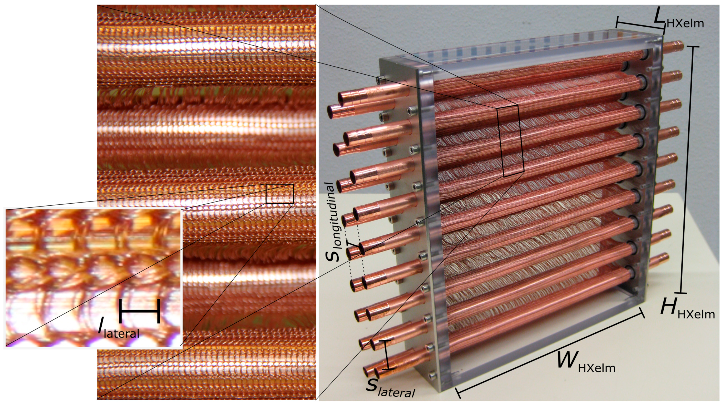
Figure 4.
Flat tube wire heat exchanger (FT WHX).
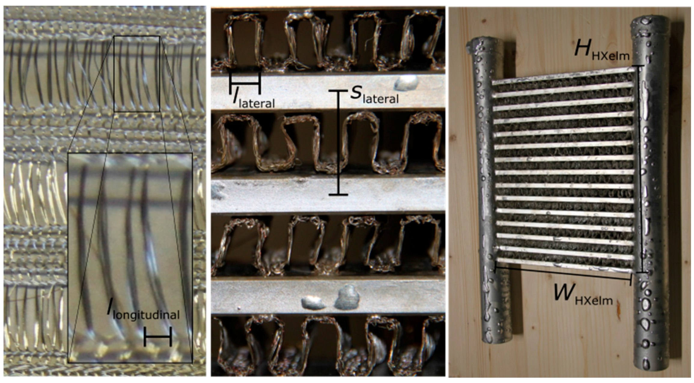
Figure 5.
Scheme of the air side of the heat exchanger test rig at Fraunhofer ISE; the air flow conditioning section is connected at the right side of the test rig [19].
Figure 5.
Scheme of the air side of the heat exchanger test rig at Fraunhofer ISE; the air flow conditioning section is connected at the right side of the test rig [19].

Figure 6.
Section of the flat tube wire heat exchanger (left) with CAD sketch (middle) and a characteristic element for fluid flow and heat transfer simulation (right). Boundary conditions for the simulations are given for the inlet, the outlet, and the solid domain. All other boundaries are symmetric.
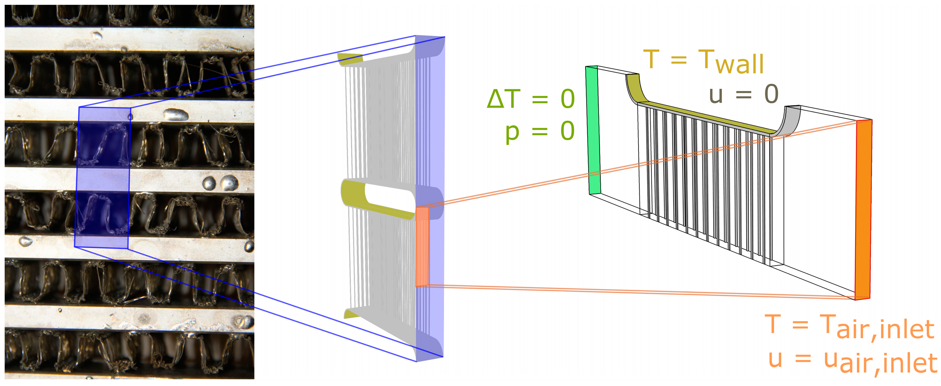
Figure 7.
CFD simulation for flow around the wire structure. 3D simulation (right) and 2D simulation (left) of the wire heat exchanger, with streamlines and colored temperature fields (red: hot; blue: cold). Bottom left: 2D simulation representing a horizontal cut of the 3D staggered heat exchanger. Top left: 2D simulation representing a heat exchanger with inline wires, as used in a later simulation.
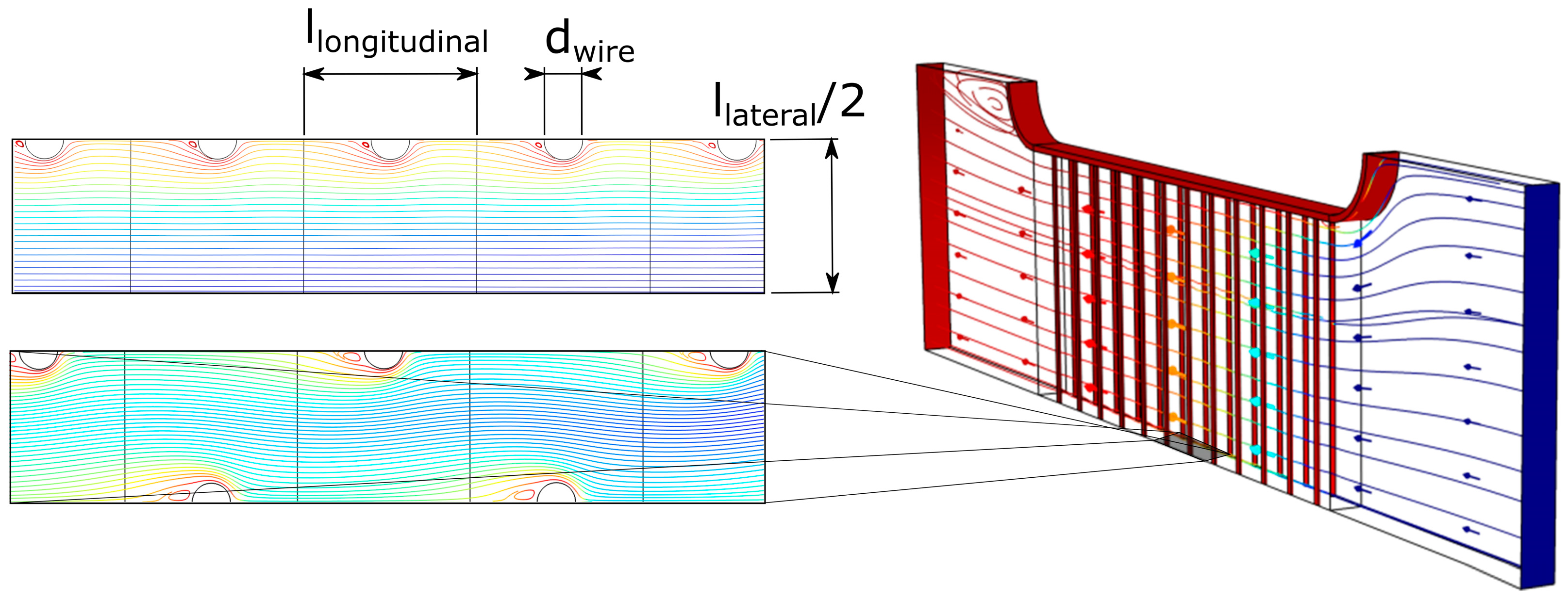
Figure 8.
Detailed view of an aluminum flat tube heat exchanger (left) with extruded tubes and louvered fins brazed between the tubes. Detailed view of a round tube copper heat exchanger (right) with wavy fins contacted by tube expansion (modified from [1]).
Figure 8.
Detailed view of an aluminum flat tube heat exchanger (left) with extruded tubes and louvered fins brazed between the tubes. Detailed view of a round tube copper heat exchanger (right) with wavy fins contacted by tube expansion (modified from [1]).
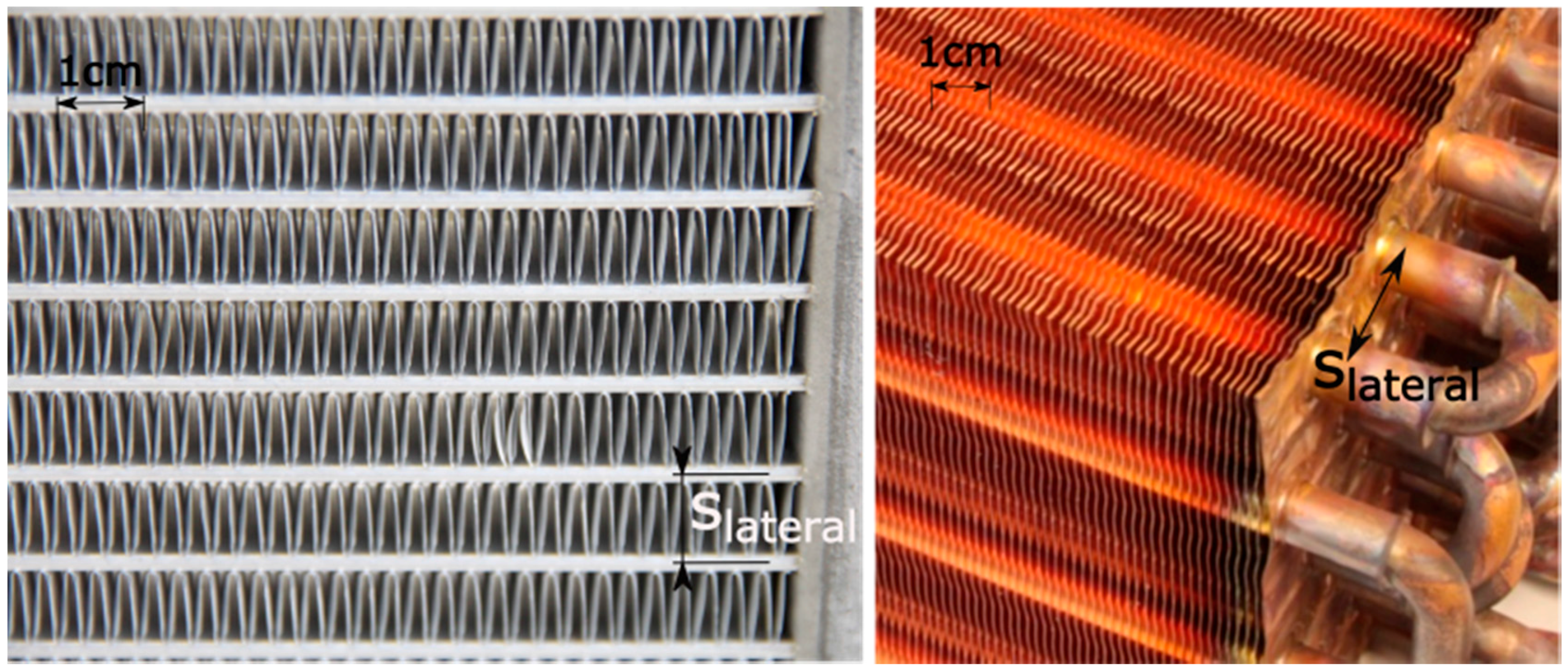
Figure 9.
Results of the measured and simulated round tube wire heat exchangers (RT WHX and RT WHX Sim1) compared to a conventional fin-and-tube heat exchanger (RT Ref) in terms of (a) energetic efficiency; (b) mass efficiency; and (c) volume efficiency as a function of the air inlet velocity of the heat exchanger.

Figure 10.
Results of the measured and simulated flat tube wire heat exchangers (FT WHX and FT WHX Sim) compared to a conventional louvered-fin flat tube heat exchanger (FT Ref) in terms of (a) energetic efficiency; (b) mass efficiency; and (c) volume efficiency as a function of the air inlet velocity of the heat exchanger.

Table 1.
Specifications of the round tube and flat tube wire heat exchangers.
| Specification | Unit | RT WHX | FT WHX |
|---|---|---|---|
| number of tubes | – | 18 | 15 |
| tubes outer dimensions × wall thickness | mm | Ø10 × 0.5 | 30 × 6.5 × 1.5 |
| tube pitch perpendicular to flow direction, | mm | 26.0 | 16.4 |
| tube pitch in flow direction, | mm | 22 | n.a. |
| tube length with contact to air side, | mm | 195 | 195 |
| wire diameter, | mm | 0.1 | 0.1 |
| material / thermal conductivity | W/mK | Cu-HCP/385 | Cu-HCP/385 |
| wire pitch perpendicular to flow direction (bundles of 4 wires), | mm | 0.77 | 5.4 |
| wire pitch in flow direction (bundles of 4 wires), | mm | n.a. | 1 |
| heat exchanger outer dimension (without headers), × × | mm3 | 195 × 231 × 32 | 195 × 231 × 30 |
| header outer dimensions × wall thickness | mm × mm | Ø40 × 1 | Ø43 × 1.7 |
| wire structure mass, | kg | 0.19 | 0.18 |
| heat transfer surface area density, | m2/m3 | 180 | 160 |
Table 2.
Definition of key figures for performance evaluation.
| Efficiency | Unit | Definition |
|---|---|---|
| energetic efficiency | 1/K | |
| mass efficiency | W/(K·kg) | |
| volume efficiency | W/(K·m3) |
© 2017 by the authors. Licensee MDPI, Basel, Switzerland. This article is an open access article distributed under the terms and conditions of the Creative Commons Attribution (CC BY) license (http://creativecommons.org/licenses/by/4.0/).
Share and Cite
MDPI and ACS Style
Fugmann, H.; Laurenz, E.; Schnabel, L. Wire Structure Heat Exchangers—New Designs for Efficient Heat Transfer. Energies 2017, 10, 1341. https://doi.org/10.3390/en10091341
AMA Style
Fugmann H, Laurenz E, Schnabel L. Wire Structure Heat Exchangers—New Designs for Efficient Heat Transfer. Energies. 2017; 10(9):1341. https://doi.org/10.3390/en10091341
Chicago/Turabian StyleFugmann, Hannes, Eric Laurenz, and Lena Schnabel. 2017. "Wire Structure Heat Exchangers—New Designs for Efficient Heat Transfer" Energies 10, no. 9: 1341. https://doi.org/10.3390/en10091341
Note that from the first issue of 2016, this journal uses article numbers instead of page numbers. See further details here.