Review

Encapsulated Nitrates Phase Change Material Selection for Use as Thermal Storage and Heat Transfer Materials at High Temperature in Concentrated Solar Power Plants

1
Facultad de Ingeniería y Ciencias, Universidad Adolfo Ibáñez, Avenida Diagonal Las Torres 2640, Peñalolén, Santiago 7941169, Chile
2
Faculty of Mechanical Engineering, Wroclaw University of Science and Technology, Lukasiewicza 5, 50-370 Wroclaw, Poland
*
Author to whom correspondence should be addressed.
Energies 2017, 10(9), 1318; https://doi.org/10.3390/en10091318
Submission received: 18 July 2017 / Revised: 20 August 2017 / Accepted: 28 August 2017 / Published: 1 September 2017
(This article belongs to the Section D: Energy Storage and Application)

Abstract

:
In the present paper, the finite element method is used to perform an exhaustive analysis of the thermal behavior of encapsulated phase change materials (EPCMs), which includes an assessment of several materials in order to identify the best combination of PCM and shell material in terms of thermal energy storage, heat transfer rate, cost of materials, limit of pressure that they can support and other criteria. It is possible to enhance the heat transfer rate without a considerable decrease of the thermal energy storage density, by increasing the thickness of the shell. In the first examination of thermomechanical coupling effects, the technical feasibility can be determined if the EPCM dimensions are designed considering the thermal expansion and the tensile strength limit of the materials. Moreover, when a proper EPCM shell material and PCM composition is used, and compared with the current storage methods of concentrated solar power (CSP) plants, the use of EPCM allows one to enhance significantly the thermal storage, reaching more than 1.25 GJ/m3 of energy density.

1. Introduction

Worldwide, high dependence on fossil fuels and the increased energy demand have set two challenges for society: (1) to identify environmentally friendly energy sources, and (2) to develop more efficient methods and technologies, in order to satisfy the high energy demands. To achieve these targets, renewable energy generation technologies have become a key factor by allowing exploitation of cleaner and abundant energy sources. Nevertheless, these technologies have their own limitations, like low capacity factor as a consequence of using variable and unpredictable primary energy sources.
In the case of concentrated solar power (CSP) plants, the intermittency problem is addressed with the use of thermal energy storage (TES) systems [1,2,3,4]. Thanks to TES the CSP plant can produce energy when no sunlight is available, then this component contributes to produce an almost continuous supply of electricity and, as consequence, increase its capacity factor. In fact, currently TES systems could increase capacity factor from 20% (no TES system) to 50% (TES system of 7.5 h) [5]. Moreover, new CSP projects are more ambitious, reaching more than 10 h of thermal storage, as the case of an under-construction solar power plant in Chile, which TES module is designed for 17.5 h. of storage obtaining a capacity factor above 80% [6]. According to Ma et al. [1], CSP plants integrated with TES can provide utility-scale, dispatchable electricity to the power grid.
Most commonly used TES commercial designs corresponds to a two-tanks system with molten salt as heat storage medium, also known as solar salt. This is a mixture composed by 60% NaNO3 and 40% KNO3 [7], but there is still space for improvement. The importance of TES in CSP plants has encouraged several researchers to achieve higher capacity factors and more efficient systems, by improving structural and operational features like energy storage density, heat transfer rate and system size, within others. Reducing the costs of TES systems is also important. Several studies have concluded that among the three types of TES (latent heat, sensible heat and thermochemical), latent heat storage (LHS) is the most attractive to store energy, since this method has higher storage densities and lower costs in comparison to sensible and thermochemical heat storages, respectively [8,9]. Since higher energy densities allow one to reduce TES material volumes and tank sizes, TES system cost is expected to decrease.

2. Phase Change Materials

LHS uses phase change materials (PCMs) as heat storage medium. These materials absorb and release energy through phase change transitions at constant temperature. Several PCMs such as hydrated salts [10], inorganic salts [11,12,13,14], paraffins [15], fatty acids [16], polyester [17] and polyether [18] have been investigated for thermal energy storage in different temperature ranges [19]. PCMs are principally classified according to their working temperature and chemical composition.
According to working temperature, they are divide into low (below 120 °C), middle (between 120 and 200 °C) and high (up to 200 °C) temperature, where PCMs with fusion temperatures inside the 300–550 °C range are compatible with currently technologies used in solar plants [9].
According to chemical composition, PCMs can be divided into organic and inorganic. Since organic PCMs’ low conductivity reduces the energy efficiency during heat charging and discharging processes [20,21], inorganic materials are preferable to organics as TES material. Moreover, compared with other PCMs, inorganic salts usually present high thermal stability and advantageous behavior for high temperatures application [22,23,24].
Inorganic PCMs include hydrated salts, inorganic salts, saline compounds and metallic alloys. Among them, inorganic salts like nitrates, sulfates, carbonates, chlorides and hydroxides with melting temperatures above 300 °C can be highlighted as storage media in solar power plants for high-temperature TES systems [8].
According to Khan et al. [25] organic PCMs is preferable to salt hydrates, for their non-corrosive nature and insignificant solubility in water. Hydrate salts are often highlighted as thermal energy storage materials, but hydrates cannot be used as TES medium on CSP plants, due to the unavailability of recombination with water during the reverse process of freezing, which results in incongruent melting [26,27].
Due to the use of PCMs like inorganic salt mixtures, it is possible to increase the energy density by 50% and reduce the cost by over 40% [28]. Nevertheless, PCMs’ solid–liquid transition has technical challenges such as the low thermal conductivity of nitrates and phase instability during melting process [26]. Therefore, PCMs require large heat transfer areas. Moreover, there are other problems such as container complexity, phase segregation and sub-cooling, which can be very severe and completely hinder stored energy extraction [9,10].
As consequence, an interesting PCM enhancement method is encapsulating the PCM with a high thermal conductivity material, therefore obtaining an encapsulated phase change material (EPCM) as heat storage medium. Using EPCM as a TES material has features that could position it as an excellent and highly efficient TES method [19].

3. EPCM State of the Art

EPCMs possess large heat transfer surface areas, allowing them to increase the heat transfer rate during charging and discharging processes [7,25]. As a consequence, the demand response of the CSP plants could be improved. Moreover, encapsulation provides a barrier between the PCM and heat transfer medium which contributes to prevent corrosion [8,29,30]. In additon, the shell barrier contributes to mitigation of sub-cooling and segregation problems during thermal cycling [31]. EPCMs’ size is relevant to enhancing the heat transfer rate. Based on size, EPCMs can be classified as nano (below 1000 nm), micro (from 1000 nm to 1000 μm) and macro (above 1000 μm) [30]. According to Alam et al. [2] between micro and macro EPCMs, micro EPCMs provide faster charging and discharging rates because of the smaller distance for heat transfer.
Shell cracking and incomplete melting process are main possible problems of using an EPCM. They occur because of the high pressure during the solid-liquid transition, as a consequences of the thermal expansion of the PCM. Among these technical challenges, incomplete melting could be observed just in very constrained situations and it could be accompanied by local recrystallizations. Instead, in order to avoid shell cracking, shell materials must be strong enough to resist high pressure imposed by solid-liquid transitions. Therefore, in order to minimize pressure and maintain structural integrity, leaving sufficient hollow space inside EPCM capsule or using high shell thickness to prevent deformation could be essential [32,33,34,35].
According to Pitié et al. [36], during melting processes PCMs should have high latent heat but low volumetric expansion, which leads to a lower pressure increase. According to Lopez et al. [32] shell cracking during heating processes could be also avoided by reducing the pore-wall rigidity, increasing pore-walls thickness or increasing pores’ connectivity. According to Parrado et al. [37] pressure decreases with time, guaranteeing that the shell will not crack, during cooling process.
Regarding the EPCM fabrication methods, according to Khan et al. [3] between chemical and physical PCM encapsulation manufacturing methods, chemical encapsulation techniques result in better heat storage capacity. The following are interesting examples of EPCMs applied as storage medium:
(1)
Cascade system is a TES technique characterized by using encapsulated salts in packed beds, which are progressively ordered according to their melting points from the bottom to the top of a single tank [38]. This method allows one to significantly increase the heat transfer rate, due to the constant melting. In fact, cascades of macro-encapsulated PCMs can store 50% more energy per unit volume than conventional two tanks system of CSP plants [39]. Compared to traditional CSP two-tank systems, the cost of such a TES system could decrease from 27 to 16 $USD/kWh, according to [40,41].
(2)
Micro-encapsulated phase change slurry (MEPCS), which consists of a suspension where PCMs are microencapsulated, enhancing heat transfer due to direct surface contact between EPCM and heat transfer fluid (HTF), without altering the physical properties of the liquid (density, viscosity) [42].
(3)
Fluidized bed storage (FBS) is similar to the packed bed of cascade system, but instead of fixed PCM, EPCMs flow inside a TES single-tank. This method allows one to work at uniform temperature and increase the heat transfer rate of micro-encapsulated PCMs [43]. High heat transfer rates can be achieved between a fluidized bed of coated PCM particles and a heat exchanging surface [44]. In circulating fluidized bed, heat transfer rate determines heat exchange surface area required, which depends on capsule diameter [44,45].
In summary, EPCMs’ potential to enhance TES system is improved by using different geometries (like tubular or spherical EPCMs), sizes (nano, micro or macro) and multiple TES applications (like cascaded systems, MEPCS’, fluidized beds, within others).

4. Methodology

The general objective of the present work was to perform an exhaustive thermal evaluation of different combinations of PCMs and shell materials, in order to identify which combination produces the highest energy density and heat transfer rate during the heat charging process.
For this purpose, a thermomechanical analysis using material properties like specific heat, density, thermal conductivity coefficient, latent heat (i.e., enthalpy of fusion and crystallization), temperature of phase change, Poisson ratio, Young’s modulus and thermal expansion coefficient is presented.

Criteria Selection for EPCM Materials

An ideal shell material should have at least the following features [31]: high thermal conductivity to ease the heat exchange between PCM and HTF, should not react with the shell, sufficient structural and thermal strength to withstand phase change process, and retain all the thermo-physical properties at the micro and nano level size, and impermeability.
Previous studies of EPCMs have been focused on copper [36], graphite [35,46], and silicon carbide [35], among others, as shell materials. Nevertheless, it is interesting to review materials used by other heat transfer enhancing methods since they could also improve the efficiency and reduce costs of the system. Also, they fulfill at least two of the most important selection criteria for shell materials: they are good thermal conductors and they do not react with PCMs.
These methods and materials are the impregnation of highly conductive porous materials like expanded graphite [47], compressed expanded natural graphite (CENG) [48], aluminum [49,50], nickel [32,51] and copper [52,53,54]. The dispersion of highly conductive particles in the PCM like nano-graphite [55], aluminum microparticles [56], silver nanoparticles [57] and copper nanoparticles [58]. Placing of metal structures in the PCM like thin walled hollow cylindrical steel structures [59] and stainless-steel balls combined with stainless steel screens [60]. The use of highly conductive and low-density materials such as carbon nanofiber additives [61].
According to Fukahori et al. [4], heat transfer rate can significantly increase (e.g., Al/Si: 40%) by using several metallic materials due to their high thermal conductivity coefficients (e.g., Cu: 400 W/m·K). However, metallic PCMs’ fusion points (e.g., Cu: 1100 °C) usually are far above feasible currently working temperature of CSP plants (300–550 °C). As consequence, metallic PCMs cannot be used for CSP plants. Nevertheless, using metallic materials as shell material is useful to enhance the heat transfer rate by increasing the PCM transition rate.
Finally, the properties of selected shell candidates are summarized in Table 1. They were selected for analysis because they are characterized by high values of thermal conductivity (e.g., SiC, silver and copper), Young’s modulus (e.g., iron, granite and silicon), volumetric density (e.g., gold, silver, nickel, iron and copper) and/or specific heat (e.g., Al/Si and SiC).
In literature there are many reviews of PCM materials and their respective properties [9,10,66,67]. The main criteria to manage the selection of PCM are usually classified into thermal, physical, chemical and economical properties, as follows [68,69]:
  • Thermal: The melting point in within the desired operating temperature range. A high latent heat of fusion per mass unit, so that a smaller amount of material stores a given amount of energy. A high specific heat to provide additional significant sensible heat storage effects. A high thermal conductivity, so that the temperature gradients for charging and discharging the storage material are reduced.
  • Physical: Small volume changes during phase transitions, so that a simple container and heat exchanger geometry can be used. High density. Exhibit little or no sub-cooling during freezing. Low vapor pressure in order to avoid stresses and problems with the container and the needed heat exchangers.
  • Chemical: Chemical stability, no chemical decomposition and corrosion to construction materials. No phase separation. They must contain non-poisonous, non-flammable and non-explosive elements/compounds.
  • Economical: Available in large quantities. Low cost.
An extensive review of TES materials was performed in order to select the PCMs presented on Table 2. They were selected due to their higher potential in comparison with several PCMs reviewed in the literature. In the case of binary and ternary salts, their eutectic composition is chosen since this weight proportion melts and freezes congruently forming a mixture of the component crystals during crystallization. Due to crystallization this mostly eliminates possible separations. Recently, eutectic salts of nitrates are widely used in solar applications because of their low melting points, low causticity, high thermal stability and reasonable commercial price [7].
The salt composed of KNO3 and NaNO3 was selected because it is currently used on CSP plants [70]. In all this work, KNO3/NaNO3 is used to represent eutectic mixture composed of 40 wt % of KNO3 and 60 wt % of NaNO3. Particularly, eutectic composition of LiNO3, NaNO3 and KNO3 is selected for allowing decrease melting point by 103 K (from 496 K to 393 K) and increase latent heat by 50 kJ/kg in comparison to KNO3/NaNO3. These improvements are attributed to the addition of LiNO3 to the mixture. In the presented paper, LiNO3/NaNO3/KNO3 is used to represent this eutectic mixture composed of 30 wt % of LiNO3, 20 wt % of NaNO3 and 50 wt % of KNO3.
In addition to these PCMs, some nitrate-free composites were also included in the simulation since it was also of interest to confirm that the nitrates have better performance as PCMs than other composites, such as MgCl2 and the salt of the eutectic mixture of MgCl2 and NaCl composed of 57 and 43 mol %, respectively, which is represented as MgCl2/NaCl.
Table 3 collects information concerning the characterization of readily-made capsules for PCMs and shell selections. In the available literature data, authors use different descriptions and characterization methods for their investigated systems. It therefor appears to be difficult and even impossible to compare heat storage covering charging/discharging range with the latent heat. To compare and present available results more comprehensibly some unification was made. The following table indicates that the usage of different shells for the same PCM significantly influences the system’s performance. For instance, the shell made of copper [83] supports the energy storage by 34 kJ/kg more efficiently than the steel [84] or polymer ones. Generally, metallic shells enhance the heat accumulation capability much more effectively than polymers. During the EPCM design process, the performance can be also adjusted by filling the same shells with different PCMs.

5. Modeling of EPCM

On this section the modeling used to calculate the thermal energy storage produced by heating EPCMs is presented.

5.1. Geometry Characterization

In this work, two concentric spheres are considered where several dimensions for external radius ( R ), internal radius ( r ) and, therefore, thickness ( T ) are used:
(1)
Geometry characterization 1: For the selections of materials, to compare in equal conditions different types of materials, R, r and T values are 1.1, 1.0 and 0.1 mm, respectively. These dimensions are selected considering previous studies under ideal conditions.
(2)
Geometry characterization 2: Using the best material combination found, , in order to analyze the pressure and the thermal storage for different shell thickness for the thermomechanical coupling, the PCM thickness is varied five times ( T i = 0.1, 0.2, 0.3, 0.4 and 0.5 mm) with R always equal to 1.1 mm and r i = R T i .
(3)
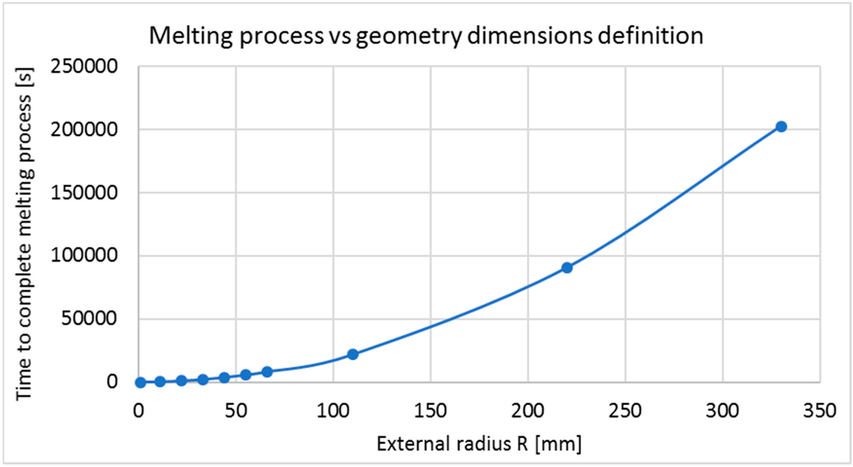
Geometry characterization 3: Using the best materials combination for thermal analysis, R and r adopt several values, keeping the relative thickness ( T relative equal to ( R i r i ) / R i   =   10 % ). For this part the following dimensions in (mm) are used for ( R i , r i ) = (1.1, 1.0), (11, 10), (22, 20), (33, 30), (55, 50), (66, 60), (77, 70), (110, 100), (220, 200), (330, 300). Since previous studies used different dimensions, making it difficult to decide a correct dimension, this evaluation is performed in order to know the effects of increasing geometry dimensions.
Thermal Assumptions: The shell is considered to be homogeneous and isotropic. The density ( ρ ), specific heat ( C p ) and thermal conductivity ( k ) are constant values. The PCM in a solid state is homogeneous.
Mechanical Assumptions: The shell has a linear elastic behavior with no-influence on the thermal behavior. For the PCM in liquid state, the pressure of the liquid within the shell is uniform. The PCM is non-deformable in a solid state.
In the Interfaces: For the external radius, a temperature imposed and heat flux continuity at the melting front, and for the shell/PCM interface, an equality of temperature and pressure is assumed.
EPCM boundary condition: The initial temperature inside the sphere is   T 0 = 293.15 K. Boundary temperature is T R = 550 K. As consequence of these conditions, the inside of the EPCM will increase its temperature from T 0   to   T R . It is important to mention that to use the latent heat of the PCM, its melting point must be within this range. The melting point of the shell must be higher than the temperature range of heating, to maintain the shell in its solid state.

5.2. Heat Transfer Modeling

5.2.1. Shell Modeling

The equation to describe the conductive heat transfer is:
ρ C p T t + · ( k T ) = Q
where   ρ is the density in (kg/m3), C p is the specific heat capacity at constant pressure in (J/(kg·K)), T is absolute temperature in (K),   t is the time in (s), k T is the heat flux by conduction in (W/m2), which depends on the temperature and the thermal conductivity, and Q represents energy storage (J).

5.2.2. Shell/PCM Interface Modeling

The heat fluxes at upside and downside boundaries depend on the temperature difference according to following relations:
n s · ( k s T s ) = h ( T p T s )
n p · ( k p T p ) = h ( T s T p )
h   =   h c   +   h g   +   h r
where n s , k s , T s . are the normal vector of the position, the thermal conductivity and temperature parameter for the shell material, respectively. And n p , k p , T p are the normal vector of the position, the thermal conductivity and temperature parameter for the PCM. The joint conductance h has three contributions: the constriction conductance ( h c ) from the contact spots, the gap conductance ( h g ) . due to the fluid at the interstitial space, and the radiative conductance ( h r ) .

5.2.3. PCM Modeling

Finally, the equation that describes the heat transfer with phase changes of the PCM is:
ρ e q C p e q T t + · ( k e q T ) = Q
where ρ e q , k e q and C p e q are the equivalent values of density, thermal conductivity and heat capacity, respectively, and Q represents energy storage.
These equivalent values depend on   θ , which represents the PCM portion in the solid phase, and they also depend on the density   ( ρ p h a s e   i ) , thermal conductivity ( k p h a s e   i ) and specific heat capacity ( C p , p h a s e   i )   . of each phase of the PCMs. In this system of equations, i   is equal to 1 for the solid state or equal to 2 for the liquid state.
ρ e q = θ ρ p h a s e 1 + ( 1 θ ) ρ p h a s e 2
k e q = θ k p h a s e 1 + ( 1 θ ) k p h a s e 2
C p e q = 1 ρ ( θ ρ p h a s e 1 C p , p h a s e 1 + ( 1 θ ) ρ p h a s e 2 C p , p h a s e 2 ) + L α m T .
where, the equivalent heat capacity ( C p e q ) . represents the energy gain provided for the sensible and latent heat, where L is the latent heat, i.e., enthalpy of fusion or crystallization, and α m defines the amount of the PCM which is under a melting process:
α m = 1 2 ( 1 θ ) ρ p h a s e 2 θ ρ p h a s e 1 θ ρ p h a s e 1 + ( 1 θ ) ρ p h a s e 2
Thus, α m T . is the variation of the fraction of PCM that is in its melting process as a function of the variation of temperature.
The software Comsol Multiphysics was used to solve this model. This is a software platform based on advanced numerical methods for modeling and simulating physics-based problems. It uses finite element method (FEM) to solve the system of equations in every node of a mesh [88].

6. Results

Results obtained from model calculation are presented in this section divided in: (1) thermo-mechanical analysis of the shell materials and (2) thermal analysis for the entire EPCM of different geometry characterizations explained in the methodology section, ending with a thermo-mechanical theory analysis of the pressure imposed by the PCM’s thermal expansion on the shell’s internal surface.

6.1. Results and Analyses of the EPCM Shell

This section focuses on thermal energy storage comparison of the nine materials presented in Table 1. The main thermal storage parameters used are thermal energy storage, thermal conductivity, Poisson ratio and Young’s modulus.
Figure 1a shows the shell materials thermal energy storage and thermal conductivity coefficient comparisons. Considering thermal conductivity coefficients, silver and copper materials highlight and show high potential to improve heat transfer rate. However, shell made of silver is the best thermal conductor by only presented thermal conductivity coefficient 7% higher than copper. This difference can be considered negligible, according thermal results presented hereafter, when entire EPCM (shell and PCM) are analyzed.
Considering these thermal energy storage results, iron, nickel and copper can be highlighted and, as consequence, show potential to improve energy density of TES systems. Between them, just copper has high potential as shell material to improve both the EPCM heat transfer rate and thermal energy storage capacity, while iron and nickel do not even reach 25% of copper’s value (400 W/m·K).
We note that most of materials with high thermal energy storage—such as iron, copper, gold, silver and aluminum—can be obtained from Chilean sources. In fact, they are some of principal minerals obtained by the mining industry of this country. This is particularly important in the case of copper, since Chile accounts with extensive reserves of this metal. Therefore, producing a shell out of one of these materials will contribute to a synergy between TES systems for CSP plants and mineral development in Chile.
Another interesting parameter as evaluation criterion for shell materials is resistance against to internal shell surface pressure, caused by PCM thermal expansion during the solid to liquid phase change transition. If this pressure exceeds a pressure equivalent to the limit of elasticity, i.e., yield strength or yield point, materials begin to deform plastically. From there onward, only the part corresponding to elastic deformation is recovered, producing an irreversible deformation due to the fact the rest of the material will go on to display a plastic behavior, which means that it will not be able to return to the initial shape. In order to maintain the initial EPCM structure, the pressure imposed by the shell must be lower than the pressure limit of shell materials. As consequence, the interest of researchers has been focused on materials with high yield strength, because these materials can expand without permanently losing their structure.
Mechanical properties used for this evaluation are Young’s modulus and Poisson ratio. The former measures the force needed to deform something and describes stress per unit of strain. The latter describes the two-dimensional axial expansion displacement. Figure 1b shows thermal energy storage and Young’s modulus shell materials comparisons of the nine types of shells, since among these two properties it is the most important, since the expansion is volumetric.
Materials with very high Young’s modulus require a higher stress to deform. However, high Young’s modulus values could cause incomplete melting processes, since the materials’ rigidity cannot allow complete thermal expansion, but at least they count with very high thermal expansion coefficients. However, low shell materials’ Young’s moduli could provoke leakage of PCM in the TES system, due to the high material deformation. Nevertheless, materials with low mechanical property values can also be used as shell materials in EPCM, if the shell materials can bear the pressure imposed by the PCMs’ thermal expansion without losing their structural integrity. Nevertheless, in case of PCM pressures higher than a pressure equal to yield strength, it is possible to decrease it by introducing an empty space at the shell/PCM interphase or increasing the shell thickness, as was shown before. Both methods reduce the shell pressure and as a consequence the thermal expansion of PCMs does not affect the EPCM structure.
Another important phenomenon [89,90,91,92,93,94] affecting capsule shells is the cyclic thermal loading during charging/discharging as well as stresses generated by the expanding PCM material. Although the repeated loads applied during solidification or melting of the PCM are below certain threshold, e.g., yield strength, after dozens of cycles microscopic cracks start to develop and when the critical size of the crack is reached, the structure fractures suddenly. Materials subjected to cyclic loading at constant amplitude stress or strain can fail after some numbers of cycles Nf or not. Simplifying, the ultimate tensile strength means that a material loses its integrity after one tension cycle, while when the applied load is lower, failure can appear after several numbers of cycles (Nf). Moreover, below a certain amplitude, there is no number of cycles that will cause failure. This means that a material can resist millions of cycles without damage (>106). Often constructed S-N (stress versus a number of cycles) curves show the level of stress named stress fatigue limit below which the material has an apparently “infinite” fatigue life. Thus, for Fe (Armco) at stress amplitude of 181 MPa or 230 MPa (see Table 3) can resist assumed standard cycle loadings of 106 or more, correspondingly, at room and 300 °C temperature. Similarly, material subjected to cycling loading with a constant strain of 0.039% (20 °C) or 0.120% (300 °C) has an infinite fatigue life. It can be seen from the table that the most resistant material is Fe, even at high temperature. Copper is very sensitive to temperature and its fatigue strength decreases almost two times. It should be noted that non-ferrous metals do not show a true endurance limit though for engineering purposes this is often defined as the stress amplitude corresponding to the fatigue life of 106 cycles.
In practice pure metals, due to their low mechanical properties, are utilized exceptionally. Though alloys exhibiting much lower thermal conductivity can be exposed to much higher stresses and elastic strains, alloying elements e.g., Si, can also increase the stress fatigue limit for Al four times at a higher temperature. Similarly, heat treated (T6 annealing and aging) Al alloys supplemented with Cu exhibit high resistance to fatigue failure. In heat storage systems including PCM melting and solidification with associated severe shrinkage voids (e.g., in the case of paraffin) rather high local strain classified as plastic could be expected. Usually, fatigue analysis based on the number of load cycles is sorted into high-cycle fatigue and low-cycle fatigue when high stresses or strain causes failure after a low number of loading cycles.
Fatigue life prediction of many materials subjected to low cycle loading but with relatively high- stress amplitude inducing plastic strain can be comprehensively described by the Coffin-Manson equation:
  ε a = ε f ( N f ) c
where εa is the plastic strain amplitude, ε f is called fatigue ductility factor reflecting the fracture strain, c is the fatigue exponent which for metals varies in relatively small range 0.4–0.6, Nf is the number of cycles to failure. Based on this relation and when two parameters have been estimated experimentally fatigue behavior and life of materials can be predicted. In effect, at observed strain and stress level it can be calculated the number of loading cycles which leads to materials failure.
Listed in Table 4 are alloys that can resist thousands of cycles when the amplitude strain is 0.5%, but when it increases to 1%, the number of cycles decreases drastically, depending on the alloys, to 4–16 times. A similar effect is observed when the temperature increases. High quality 2024 aluminum alloy (UTS = 420 MPa) at 1% amplitude strain cracks after 2614 cycles but after only 444 at 300 °C. The most fatigue-resistant alloys are Ni-based alloys which can be loaded with very high amplitude stresses.
Previous results consider only the thermal results of sensible shell heating, which belong just to the EPCM external part. However, EPCMs’ total amount of energy includes PCM latent and sensible heating, in addition to shell sensible heating. The next section focuses on thermal energy storage capacity and heat transfer rate analyses of nine EPCM compositions, using three types of PCMs covered by three types of shell material.

6.2. Results and Analyses of EPCMs (Geometry Characterization 1)

PCMs used on this section are LiNO3, KNO3/NaNO3 and LiNO3/KNO3/NaNO3 because they possess higher thermal energy storage than the other PCMs of Table 2, when a temperature range which contains all melting point temperatures (293 to 1000 K) is used. This range is useful for comparison under equal conditions, i.e., including the enthalpy of fusion, due to the fact it contains all the melting temperatures of the six PCMs, but is not coherent with any current CSP working temperature range (293 to 550 °C).
In addition, the three PCMs selected have melting points within a delta working temperature mentioned before i.e., ∆T = 357 K, being also coherent with the normal range of CSP plants mentioned before. Figure 2 shows the thermal energy storage behavior of these three types of EPCMs when covered by a nickel shell under the same thermal conditions. The graph shows the storage process just until second 15, which is the moment when all reach the thermal equilibrium at 550 K. The cooling process is not considered on this model, so consequently, all the cases remain constant after reaching this temperature. Other tested shell materials are composed of copper and iron, selected in previous analyses.
According to Figure 2, LiNO3 has the highest thermal energy storage capacity, reaching 8.3 J per EPCM, followed by the ternary salt LiNO3/KNO3/NaNO3, 6.3 J per EPCM, while the worst PCM performance is presented by KNO3/NaNO3 reaching only 5.6 J per EPCM. Despite the fact the thermal storage capacity of LiNO3 is higher than that of the other two PCMs, it takes 50% more time to store that amount of energy (as is shown in Figure 3).
Regarding shell materials, thermal energy storage curves for the same PCM with different coatings have almost same evolution independent of what type of shell material is used to cover it. In addition, the thermal storage capacity difference is negligible and does not depend on the shell, when a shell with 0.1 mm thickness is used.
A comparison of thermal energy density and heat transfer rate influence of different core/coat combinations of EPCM is shown in Figure 3. The energy density of the shell material (amount of energy per volume unit) is used since it facilitates interpretation of how much volume of EPCM material is needed to fulfill the TES system requirements.
Figure 3 shows that, considering the average thermal energy density and average heat storage rate of shells, LiNO3 exhibits the highest energy density. Also, LiNO3 has 37% better thermal storage capacity than KNO3/NaNO3, while LiNO3/KNO3/NaNO3 has 20% better than KNO3/NaNO3, so LiNO3 has the best performance in the thermal storage category, but LiNO3/KNO3/NaNO3 could be a better PCM option for TES in CSP plants, due to its good thermal conductivity that allows an enhancement of the storage rate by 98%, while the LiNO3 storage rate just is 30% greater than that of KNO3/NaNO3.
Another key parameter for EPCM selection is material costs. In the case of LiNO3, KNO3/NaNO3 and LiNO3/KNO3/NaNO3, their costs are 4000, 717 and 1807 $USD/t, respectively [96]. These prices were calculated by a weight ponderation of each nitrate within each mixture. Finally, adding this third criterion to energy density and heat storage rate criteria, it is possible to conclude that the best thermo-economical PCM option is provided by the ternary salt LiNO3/KNO3/NaNO3.
Moreover, regarding the shell materials, nickel always presents the best behavior for the three PCM cases on both thermal energy storage and heat storage rate. Despite the fact nickel has a coefficient of thermal conductivity of only 25% of the copper value, an EPCM covered with nickel always has the best heat storage rate, because nickel can store higher amounts of thermal energy, compensating for its low thermal conductivity.
Nevertheless, Figure 4 confirms that difference between these three types of shell is negligible, since nickel has just 3% more of the energy density and heat storage rate than iron. Moreover, nickel has an equal value of energy density and just 1% higher heat storage rate than copper. The only criterion that shows a significant difference between the shells is the cost of materials, since iron, copper and nickel materials cost 55, 4000 and 8000 $USD/t, respectively [96]. As consequences, iron is the best thermo-economical option to encapsulate PCMs.
If the thermal energy storage of the best combination is compared with the current TES system of sensible heating of solar salt, an energy density increase of 63%, from 756 to 1230 MJ/m3, when r = 1.0 and R = 1.1 mm EPCM radius dimensions are used is possible [97,98].
Moreover, using as an example a CSP plant that needs to supply 17,244,526 kWh of annual energy, Table 5 presents a comparison between a two-tank storage system of common molten salt and an EPCM single-tank system, using an EPCM composed by LiNO3/KNO3/NaNO3 and three different shells. The results show that considering just the cost of materials and cost of tanks, it will be necessary to incur a total cost of 34,150,053 ($USD) instead of 44,281,791.09 ($USD), which implies a 30% cost reduction when the EPCM (LiNO3/KNO3/NaNO3 covered by iron) is used instead of traditional sensible storage (KNO3/NaNO3).
Nevertheless, in addition to material costs, fabrication costs could be significantly relevant and make using EPCMs for TES systems in CSP plants economically unfeasible.

6.3. Results and Analyses of EPCM Dimensions Variation

To complement this study, the best EPCM composition, i.e., LiNO3/KNO3/NaNO3 covered by iron, is used to perform a first approach to a thermo-mechanical effects analysis of dimension variations.

6.3.1. Thickness Variation (Geometry Characterization 2)

Figure 5 shows the shell tensile behavior, EPCM heat storage rate and EPCM energy density, using different thicknesses of iron shell. The variation implies an internal radius reduction, keeping external radius dimension of R = 1.1 mm.
When the shell thickness increases from 0.1 to 0.5 mm, the EPCM energy density decreases from 0.98 to 0.91 J/s and the heat storage rate increases from 1.0 to 2.2 J/s. As a consequence, the heat storage rate increase 220% and the thermal density only decreases 6%.
Regarding the mechanical effect of this, the shell tensile strength caused by the PCM thermal expansion decreases from 1522.9 to 218.4 MPa, considering the von Mises equivalent tensile strength. This means that, for example, for 0.5 mm of shell thickness, the shell doesn’t crack because its ultimate tensile strength is 220 MPa, but a copper shell has plastic behavior would be near its cracking point and this is a risky condition for the material.
Since this is only a first approach to thermo-mechanical behavior, variation of mechanical properties is considered as thermal effects of variations of melting temperature caused by pressure effects.

6.3.2. Radius Variation (Geometry Characterization 3)

Previous studies stated that lower EPCM sizes lead to higher heat transfer rates. In order to verify this and gain a better understanding of geometry definition effects, several EPCM dimensions will be used to measure the time required to melt the PCM. For this study ten EPCM dimensions are used, as was mentioned in the third geometry definition of the modeling section.
Figure 6 shows that the dependence between the defined radius and the time required to complete the melting process is non-linear. For example, when the external dimension increases 100% (from 110 to 220 mm), the melting time increases almost 300%. This dependence can be approximated by an exponential curve, which indicates that it is not convenient to use high radius dimensions, as was shown in previous studies.

7. Conclusions

The results obtained from this work show that the most promising EPCM is composed on LiNO3/KNO3/NaNO3 as PCM and iron as shell material. In comparison to the others this composition possesses great heat transfer rate, thermal energy storage and materials cost characteristics. An important point to notice about the result is the low importance of the thermal conductivity of the shell when it is considered all EPCM.
Selection of component materials for capsules should consider the thermal expansion of the PCM and the fatigue properties of shells. Thermo-mechanical cycling loading, even at relatively low-stress amplitude, after hundreds of cycles, can generate high strain, deformation and finally damage the capsule. For materials that exhibit high thermal expansion, which solidify with large shrinkage voids, steel strength will be appropriate, though slightly weaker refined aluminum alloys are characterized by much better thermal conductivity.

8. Future Works

Among the probable and certain advantages of using z single-tank system filled with an EPCM, instead of a traditional two-tank molten salt system, there is the lower amount of materials inside the tanks and lower tank size needed to store the same amount of energy; reduction of the number of tanks from 2 to 1; increase of the CSP capacity factor; higher rate of response in case of an increasing electricity demand, because of higher heat transfer rate; reduction of pump use, since molten salt is not circulating and, partial or complete reduction of the heat tracing system, currently used to maintain salt in a liquid state.
As a consequence, these potential CSP plant enhancements can improve the supply-demand balance, providing a higher plant capacity factor. At the economic level, that implies a lower LCOE (mainly caused by the increase of incomes from electricity generation, but also because of a reduction in the cost of operation, management and investment), making CSP more attractive to investors and creating space for the growth of new markets, especially in Chile, since this country has excellent solar irradiation conditions and reserves of the materials which make up the EPCMs.
A full thermo-mechanical model will be developed to further understand the physical relations between PCMs and shells in order to discover and validate new EPCM materials. However, our preliminary EPCM thermo-mechanical results showed that to generate an empty space inside capsule is not strictly necessary, since that method could be replaced by finding the optimal dimensions of the external (R) and internal (r) radius of the shell. These optimal radii are easy to identify by using the yield strength property values of potential shell materials to calculate their von Mises equivalent tensile strength values. A correct radius combination allows avoiding both shell cracking and incomplete melting of the PCM during the charging process. Moreover, increasing the shell thickness allows one to use shell material candidates with regular or bad thermal conductivity property values, because of this enhances significantly the heat transfer rate, without hindering the thermal energy storage capacity.

Acknowledgments

This work was supported in Chile by the projects CONICYT/FONDECYT/1151061, CONICYT/FONDAP/15110019 (SERC-CHILE), ACCUSOL (ERANET-Lac, Cod. No. ELEC2015/T06-0523), Universidad Adolfo Ibáñez and by THEMSYS Initiative (UAI-Earth).

Author Contributions

Gustavo Cáceres and Karina Fullenkamp designed and performed the research. Karina Fullenkamp and Macarena Montané conceived the writing of the paper. Krzysztof Naplocha and Anna Dmitruk gave review suggestions on the writing process, corrections and review of entire paper.

Conflicts of Interest

The authors declare no conflict of interest. The founding sponsors had no role in the design of the study; in the collection, analyses, or interpretation of data; in the writing of the manuscript, and in the decision to publish the results.

References

  1. Ma, Z.; Glatzmaier, G.; Mehos, M. Fluidized bed technology for concentrating solar power with thermal energy storage. J. Sol. Energy Eng. 2014, 136, 031014. [Google Scholar] [CrossRef]
  2. Alam, T.E.; Dhau, J.S.; Goswami, D.Y.; Stefanakos, E. Macroencapsulation and characterization of phase change materials for latent heat thermal energy storage systems. Appl. Energy 2015, 154, 92–101. [Google Scholar] [CrossRef]
  3. Khan, Z.; Khan, Z.; Ghafoor, A. A review of performance enhancement of PCM based latent heat storage system within the context of materials, thermal stability and compatibility. Energy Convers. Manag. 2016, 115, 132–158. [Google Scholar] [CrossRef]
  4. Fukahori, R.; Nomura, T.; Zhu, C.; Sheng, N.; Okinaka, N.; Akiyama, T. Macro-encapsulation of metallic phase change material using cylindrical-type ceramic containers for high-temperature thermal energy storage. Appl. Energy 2016, 170, 324–328. [Google Scholar] [CrossRef]
  5. U.S. Department of Energy. 2010 Solar Technologies Market Report; National Renewable Energy Laboratory (NREL): Golden, CO, USA, 2011.
  6. Green, A.; Diep, C.; Dunn, R.; Dent, J. High capacity factor CSP-PV hybrid systems. Energy Procedia 2015, 69, 2049–2059. [Google Scholar] [CrossRef]
  7. Liu, M.; Saman, W.; Bruno, F. Review on storage materials and thermal performance enhancement techniques for high temperature phase change thermal storage systems. Renew. Sustain. Energy Rev. 2012, 16, 2118–2132. [Google Scholar] [CrossRef]
  8. Deng, Y.; Li, J.; Qian, T.; Guan, W.; Wang, X. Preparation and Characterization of KNO3/diatomite Shape-stabilized Composite Phase Change Material for High Temperature Thermal Energy Storage. J. Mater. Sci. Technol. 2017, 33, 198–203. [Google Scholar] [CrossRef]
  9. Cárdenas, B.; León, N. High temperature latent heat thermal energy storage: Phase change materials, design considerations and performance enhancement techniques. Renew. Sustain. Energy Rev. 2013, 27, 724–737. [Google Scholar] [CrossRef]
  10. Zalba, B.; Marín, J.; Cabeza, L.; Mehling, H. Review on thermal energy storage with phase change: Materials, heat transfer analysis and applications. Appl. Therm. Eng. 2003, 23, 251–283. [Google Scholar] [CrossRef]
  11. Zhang, J.; Wang, S.S.; Zhang, S.D.; Tao, Q.H.; Pan, L.; Wang, Z.Y.; Zhang, Z.P.; Lei, Y.; Yang, S.K.; Zhao, H.P. In situ synthesis and phase change properties of Na2SO4 10H2O SiO2 solid nanobowls toward smart heat storage. J. Phys. Chem. C 2011, 115, 20061–20066. [Google Scholar] [CrossRef]
  12. Lopez, J.; Acem, Z.; Palomo Del Barrio, E. KNO3/NaNO3—Graphite materials for thermal energy storage at high temperature: Part II—Phase transition properties. Appl. Therm. Eng. 2010, 30, 1586–1593. [Google Scholar] [CrossRef]
  13. Wang, T.; Mantha, D.; Reddy, R.G. Thermal stability of the eutectic composition in LiNO3-NaNO3-KNO3 ternary system used for thermal energy storage. Sol. Energy Mater. Sol. Cells 2012, 100, 162–168. [Google Scholar] [CrossRef]
  14. Ping, W.; Harrowell, P.; Byrne, N.; Angell, C.A. Composition dependence of the solid state transitions in NaNO3/KNO3 mixtures. Thermochim. Acta 2009, 486, 27–31. [Google Scholar] [CrossRef]
  15. Sanusi, O.; Warzoha, R.; Fleischer, A.S. Energy storage and solidification of paraffin phase change material embedded with graphite nanofibers. Int. J. Heat Mass Transfer 2011, 54, 4429–4436. [Google Scholar] [CrossRef]
  16. Cai, Y.; Xu, X.; Gao, C.; Bian, T.; Qiao, H.; Wei, Q. Structural morphology and thermal performance of composite phase change materials consisting of capric acid series fatty acid eutectics and electrospun polyamide6 nanofibers for thermal energy storage, Mate. Mater. Lett. 2012, 89, 43–46. [Google Scholar] [CrossRef]
  17. Cai, Y.; Song, L.; He, Q.; Yang, D.; Hu, Y. Preparation, thermal and flammability properties of a novel form-stable phase change materials based on high density polyethylene/poly(ethylene-co-vinyl acetate)/organophilic montmorillonite nanocomposites/paraffin. Energy Convers. Manag. 2008, 49, 2055–2062. [Google Scholar] [CrossRef]
  18. Feng, L.L.; Zheng, J.; Yang, H.Z.; Guo, Y.L.; Li, W.; Li, X.G. Preparation and characterization of polyethylene glycol/active carbon composites as shapestabilized phase change materials. Sol. Energy Mater. Sol. Cells 2010, 95, 644–650. [Google Scholar] [CrossRef]
  19. Guo, Q.; Wang, T. Study on preparation and thermal properties of sodium nitrate/silica composite as shape-stabilized phase change material. Thermochim. Acta 2015, 613, 66–70. [Google Scholar] [CrossRef]
  20. Mills, A.; Farid, M.; Selman, J.R.; Al-Hallaj, S. Thermal conductivity enhancement of phase change materials using a graphite matrix. Appl. Therm. Eng. 2006, 26, 1652–1661. [Google Scholar] [CrossRef]
  21. Wang, Q.; Wong, T.J.; Xia, L. Preparation and thermal characterization of expanded graphite/paraffin composite phase change material. Carbon 2010, 48, 2538–2548. [Google Scholar]
  22. Kenisarin, M.M. High-temperature phase change materials for thermal energy storage. Renew. Sustain. Energy Rev. 2010, 14, 955–970. [Google Scholar] [CrossRef]
  23. Tamme, T.; Bauer, J.; Buschle, D.; Müller-Steinhagen, H.; Steinmann, W.D. Latent heat storage above 120 °C for applications in the industrial process heat sector and solar power generation. Int. J. Energy Res. 2008, 32, 264–271. [Google Scholar] [CrossRef]
  24. Mao, A.; Park, J.H.; Han, G.Y.; Seo, T.; Kang, Y. Heat transfer characteristics of high temperature molten salt for storage of thermal energy. Korean J. Chem. Eng. 2010, 27, 1452–1457. [Google Scholar] [CrossRef]
  25. Chen, J.C.; Eichlberger, J.L. Encapsulated Phase Change Thermal Energy Storage Materials. U.S. Patent 4504402, 12 March 1985. [Google Scholar]
  26. Sharma, A.; Tyagi, V.V.; Chen, C.R.; Buddhi, D. Review on thermal energy storage with phase change materials and applications. Renew. Sustain. Energy Rev. 2009, 13, 318–345. [Google Scholar] [CrossRef]
  27. Jiang, Z.; Leng, G.; Ye, F.; Ge, Z.; Liu, C.; Wang, L.; Huang, Y.; Ding, Y. Form-stable LiNO3-NaNO3-KNO3-Ca(NO3)2/calcium silicate composite phase change material (PCM) for mid-low temperature thermal energy storage. Energy Convers. Manag. 2015, 106, 165–172. [Google Scholar] [CrossRef]
  28. Mathur, A.; Kasetty, R.; Oxley, J.; Mendez, J.; Nithyanandam, K. Using encapsulated phase change salts for concentrated solar power plant, for Solar PACES 2013. Energy Procedia 2014, 49, 908–915. [Google Scholar] [CrossRef]
  29. Jacob, R.; Bruno, F. Review on shell materials used in the encapsulation of phase change materials for high temperature thermal energy storage. Renew. Sustain. Energy Rev. 2015, 48, 79–87. [Google Scholar] [CrossRef]
  30. Qian, T.; Li, J.; Min, X.; Deng, Y.; Guan, W.; Ning, L. Diatomite: A promising natural candidate as carrier material for low, middle and high temperature phase change material. Energy Convers. Manag. 2015, 98, 34–45. [Google Scholar] [CrossRef]
  31. Salunkhe, P.B.; Shembekar, P.S. A review on effect of phase change material encapsulation on the thermal performance of a system. Renew. Sustain. Energy Rev. 2012, 16, 5603–5616. [Google Scholar] [CrossRef]
  32. Lopez, J.; Cáceres, G.; Palomo Del Barrio, E.; Jomaa, W. Confined melting in deformable porous media: A first attempt to explain the graphite/salt composites behavior. Int. J. Heat Mass Transfer 2010, 53, 1195–1207. [Google Scholar] [CrossRef]
  33. Blaney, J.J.; Neti, S.; Misiolek, W.Z.; Oztekin, A. Stresses in containment capsule for encapsulated phase change materials. Appl. Therm. Eng. 2013, 50, 555–561. [Google Scholar] [CrossRef]
  34. Blaney, J.J. Stresses in Containment Vessels for Encapsulated Phase Change Materials. Master’s Thesis, Lehigh University, Bethlehem, PA, USA, 2010. [Google Scholar]
  35. Mehling, H.; Cabeza, L. Phase change materials and their basic properties. Therm. Energy Storage Sustain. Energy Consum. 2007, 234, 257–277. [Google Scholar]
  36. Pitié, F.; Zhao, C.Y.; Cáceres, G. Thermo-mechanicalanalysis of ceramic encapsulated phase-change material (PCM) particles. Energy Environ. Sci. 2011, 4, 2117–2124. [Google Scholar] [CrossRef]
  37. Parrado, C.; Cáceres, G.; Bize, F.; Bubnovich, V.; Baeyens, J.; Degrève, J.; Zhang, H.L. Thermo-mechanical analysis of copper-encapsulated NaNO3–KNO3. Chem. Eng. Res. Des. 2015, 93, 224–231. [Google Scholar] [CrossRef] [Green Version]
  38. Zhao, W. Characterization of encapsulated phase change materials for thermal energy storage. Ph.D. Thesis, Lehigh University, Bethlehem, PA, USA, 2013. [Google Scholar]
  39. Zhang, H.; Baeyens, J.; Cáceres, G.; Degrève, J.; Lv, Y. Thermal energy storage: Recent developments and practical aspects. Prog. Energy Combust. Sci. 2016, 53, 1–40. [Google Scholar] [CrossRef]
  40. Thermal Energy Storage (TES) for Concentrating Solar Power (CSP). Available online: http://www.energy.ca.gov/research/notices/2012-08-23_workshop/presentations/3-1_Terrafore_CEC_Workshop.pdf (accessed on 29 August 2017).
  41. Flueckiger, S.M.; Yang, Z.; Garimella, S.V. Design of Molten-Salt Thermocline Tanks for Solar Thermal Energy Storage; CTRC Research Publications, Paper 191; Purdue University: West Lafayette, IN, USA, 2013. [Google Scholar]
  42. Chen, B.; Wang, X.; Zeng, R.; Zhang, Y.; Niu, J. An experimental study of convective heat transfer with microencapsulated phase change material suspension: Laminar flow in a circular tube under constant heat flux. Exp. Therm. Fluid Sci. 2008, 32, 1638–1646. [Google Scholar] [CrossRef]
  43. Izquierdo, M. Heat Transfer and tHermal Storage in Fixed and Fluidized Beds of Phase Change Material. Ph.D. Thesis, Universidad Carlos III de Madrid, Madrid, Spain, 2014. [Google Scholar]
  44. Pitié, F.; Zhao, C.Y.; Baeyens, J.; Degrève, J.; Zhang, H.L. Circulating fluidized bed heat recovery/storage and its potential to use coated phase-change-material (PCM) particles. Appl. Energy 2013, 109, 505–513. [Google Scholar] [CrossRef]
  45. Peng, H.; Dong, H.; Ling, X. Thermal investigation of PCM-based high temperature thermal energy storage in packed bed. Energy Convers. Manag. 2014, 81, 420–427. [Google Scholar] [CrossRef]
  46. Lopez, J. Nouveaux Matériaux Graphite/Selpour le Stockage D’énergie à haute Température. Étude Despropriétés de Changement de Phase. Ph.D. Thesis, Université Bordeaux 1, Bordeaux, France, 2007. [Google Scholar]
  47. Mehling, H.; Hiebler, S.; Ziegler, F. Latent heat storage using a PCM-graphite composite material. In Proceedings of the 8th International Conference on Thermal Energy Storage, Stuttgart, Germany, 28 August–1 September 2000. [Google Scholar]
  48. Py, X.; Regis, O.; Sylvain, M. Paraffin/porous-graphite-matrix composite as a high and constant power thermal storage material. Int. J. Heat Mass Transf. 2001, 44, 2727–2737. [Google Scholar] [CrossRef]
  49. Bauer, C.; Wirtz, R.A. Thermal characteristics of a compact, passive thermal energy storage device. In Proceedings of the 2000 ASME IMECE, Orlando, FL, USA, 5–10 November 2000; pp. 1–7. [Google Scholar]
  50. Tong, X.; Khan, T.A.; Amin, M.R. Enhancement of heat transfer by inserting a metal matrix into a phase change material. Numer. Heat Transf. Part A Appl. 1996, 30, 125–141. [Google Scholar] [CrossRef]
  51. Xiao, X.; Zhang, P.; Li, M. Preparation and thermal characterization of paraffin/metal foam composite phase change material. Appl. Energy 2013, 112, 1357–1366. [Google Scholar] [CrossRef]
  52. Li, Z.; Wu, Z.G. Numerical study on the thermal behavior of phase change materials (PCMs) embedded in porous metal matrix. Sol. Energy 2014, 99, 172–184. [Google Scholar] [CrossRef]
  53. Zhao, H.Y.; Lu, W.; Tian, Y. Heat transfer enhancement for thermal energy storage using metal foams embedded within phase change materials (PCMs). Sol. Energy 2010, 84, 1402–1412. [Google Scholar] [CrossRef]
  54. Vadwala, P. Thermal energy storage in metal foams filled with paraffin wax. Master’s Thesis, University of Toronto, Toronto, ON, Canada, 2011. [Google Scholar]
  55. Li, M. A nano-graphite/paraffin phase change material with high thermal conductivity. Appl. Energy 2013, 106, 25–30. [Google Scholar] [CrossRef]
  56. Mettawee, E.S.; Assassa, G.M.R. Thermal conductivity enhancement in a latent heat storage system. Sol. Energy 2007, 81, 839–845. [Google Scholar] [CrossRef]
  57. Zeng, J.L.; Sun, L.X.; Xu, F.; Tan, Z.C.; Zhang, Z.H.; Zhang, J.; Zhang, T. Study of a PCM based energy storage system containing Ag nanoparticles. J. Therm. Anal. Calorim. 2007, 87, 369–373. [Google Scholar] [CrossRef]
  58. Khodadadi, J.M.; Hosseinizadeh, S.F. Nanoparticle-enhanced phase change materials (NEPCM) with great potential for improved thermal energy storage. Int. Commun. Heat Mass Transf. 2007, 34, 534–543. [Google Scholar] [CrossRef]
  59. Velraj, R.; Seeniraj, R.V.; Hafner, B.; Faber, C.; Schwarzer, K. Heat transfer enhancement in a latent heat storage system. Sol. Energy 1999, 65, 171–180. [Google Scholar] [CrossRef]
  60. Ettouney, H.M.; Alatiqi, I.; Al-Sahali, M.; Al-Ali, S.A. Heat transfer enhancement by metal screens and metal spheres in phase change energy storage systems. Renew. Energy 2004, 29, 841–860. [Google Scholar] [CrossRef]
  61. Elgafy, A.; Lafdi, K. Effect of carbon nanofiber additives on thermal behavior of phase change materials. Carbon 2005, 43, 3067–3074. [Google Scholar] [CrossRef]
  62. Lide, D.R. CRC Handbook of Chemistry and Physics; CRC Press Inc.: Boca Raton, FL, USA, 2009. [Google Scholar]
  63. COMSOL. Multiphysics, version 5.2a; Virtual Library of Materials; COMSOL: Stockholm, Sweden, 2016.
  64. Sharma, N.K.; Misra, R.K.; Sharma, S. Modeling of thermal expansion behavior of densely packed Al/SiC composites. Int. J. Solids Struct. 2016, 102–103, 77–88. [Google Scholar] [CrossRef]
  65. Stadler, F.; Antrekowitsch, H.; Fragner, W.; Kaufmann, H.; Pinatel, E.R.; Uggowitzer, P.J. The effect of main alloying elements on the physical properties of Al–Si foundry alloys. Mater. Sci. Eng. A 2013, 560, 481–491. [Google Scholar] [CrossRef]
  66. Kuravi, S.; Trahan, J.; Goswami, D.Y.; Rahman, M.M.; Stefanakos, E.K. Thermal energy storage technologies and systems for concentrating solar power plants. Prog. Energy Combust. Sci. 2013, 39, 285–402. [Google Scholar] [CrossRef]
  67. Agyenim, F.; Hewitt, N.; Eames, P.; Smyth, M. A review of materials, heat transfer and phase change problem formulation for latent heat thermal energy storage systems (LHTESS). Renew. Sustain. Energy Rev. 2010, 14, 615–628. [Google Scholar] [CrossRef]
  68. Abhat, A. Low temperature latent heat thermal energy storage: Heat storage materials. Sol. Energy 1983, 30, 313–332. [Google Scholar] [CrossRef]
  69. Jegadheeswaran, S.; Pohekar, S.D. Performance enhancement in latent heat thermal storage system: A review. Renew. Sustain. Energy Rev. 2009, 13, 2225–2244. [Google Scholar] [CrossRef]
  70. Vignarooban, K.; Xu, X.; Arvay, A.; Hsu, K.; Kannan, A.M. Heat transfer fluids for concentrating solar power systems—A review. Appl. Energy 2015, 146, 383–396. [Google Scholar] [CrossRef]
  71. Patnaik, P. Handbook of Inorganic Chemicals; McGraw-Hill: New York, NY, USA, 2003. [Google Scholar]
  72. Fossile, L.M. Comparison and simulation of salt-ceramic composites for use in high temperature concentrated solar power. Master’s Thesis, University of Nevada, Las Vegas, NV, USA, 2012. [Google Scholar]
  73. Lachheb, M.; Adili, A.; Albouchi, F.; Mzali, F.; Nasralla, S.B. Thermal properties improvement of Lithium nitrate/Graphite composite phase change materials. Appl. Therm. Eng. 2016, 102, 922–931. [Google Scholar] [CrossRef]
  74. Hübner, S.; Eck, M.; Stiller, C.; Seitz, M.; Hübner, S. Techno-economic heat transfer optimization of large scale latent heat energy storage systems in solar thermal power plants. Appl. Therm. Eng. 2016, 98, 483–491. [Google Scholar] [CrossRef] [Green Version]
  75. Janz, G.J.; Allen, C.B.; Bansal, N.P.; Murphy, R.M.; Tomkins, R.P.T. Physical Properties Data Compilations Relevant to Energy Storage. II. Molten Salts: Data on Single and Multi-Component Salt Systems; U.S. Department of Commerce, National Bureau of Standards: Gaithersburg, MD, USA, 1978.
  76. Nunes, V.M.B.; Queirós, C.S.; Lourenço, M.J.V.; Santos, F.J.V.; Nieto de Castro, C.A. Molten salts as engineering fluids—A review Part I. Molten alkali nitrates. Appl. Energy 2016, 183, 603–611. [Google Scholar] [CrossRef]
  77. Zhang, H.L.; Baeyens, J.; Degrève, J.; Cáceres, G.; Segal, R.; Pitié, F. Latent heat storage with tubular-encapsulated phase change materials (PCMs). Energy 2014, 76, 66–72. [Google Scholar] [CrossRef] [Green Version]
  78. Williams, D.F. Assessment of Candidate Molten Salt Coolants for the NGNP/NHI Heat Transfer Loop; ORNL/TM-2006/69; Nuclear Science and Technology Division, Oak Ridge National Laboratory: Oak Ridge, TN, USA, 2006.
  79. Neti, S. Novel Thermal Storage Technologies for Concentrating Solar Power Generation; Research Performance Progress Report; Lehigh University: Bethlehem, PA, USA, 2011. [Google Scholar]
  80. Janz, G.J. Thermodynamic and Transport Properties for Molten Salts: Correlation Equations for Critically Evaluated Density, Surface Tension, Electrical Conductance, and Viscosity Data; American Institute of Physics: Park City, MD, USA, 1988. [Google Scholar]
  81. Roget, F.; Favotto, C.; Rogez, J. Study of the KNO3–LiNO3 and KNO3–NaNO3–LiNO3 eutectics as phase change materials for thermal storage in a low-temperature solar power plant. Sol. Energy 2013, 95, 155–169. [Google Scholar] [CrossRef]
  82. Villada, C.; Bolívar, F.; Jaramillo, F.; Castaño, J.G.; Echeverría, F. Thermal evaluation of molten salts for solar thermal energy storage. Renew. Energy Power Qual. J. 2014, 1, 622–625. [Google Scholar] [CrossRef]
  83. Zheng, Y.; Barton, J.; Tuzla, K.; Chen, J.; Neti, S.; Oztekin, A.; Misiolek, W. Experimental and computational study of thermal energy storage with encapsulated NaNO3 for high temperature applications. Sol. Energy 2015, 115, 180–194. [Google Scholar] [CrossRef]
  84. Munoz-Sanchez, B.; Iparraguirre-Torres, I.; Madina-Arrese, V.; Izagirre-Etxeberria, U.; Unzurrunzaga-Iturbe, A.; Garcia-Romero, A. Encapsulated high temperature PCM as active filler material in a thermocline-based thermal storage system. Energy Procedia 2015, 69, 937–946. [Google Scholar] [CrossRef] [Green Version]
  85. Nomura, T.; Okinaka, N.; Akiyama, T. Technology of latent heat storage for high temperature application: A review. Iron Steel Inst. Jpn. 2010, 50, 1229–1239. [Google Scholar] [CrossRef]
  86. Cao, L.; Su, D.; Tang, Y.; Fang, G.; Tang, F. Properties evaluation and applications of thermal energy storage materials in buildings. Renew. Sustain. Energy Rev. 2015, 48, 500–522. [Google Scholar] [CrossRef]
  87. Alam, T. Experimental investigation of encapsulated phase change materials for thermal energy storage, and applications. Ph.D. Thesis, University of South Florida, Tampa, FL, USA, 2015. [Google Scholar]
  88. COMSOL. Heat Transfer Module: User’s Guide, version 5.2a; COMSOL: Stockholm, Sweden, 2016. [Google Scholar]
  89. Nicoletto, G.; Riva, E.; Di Filippo, A. High Temperature Fatigue Behavior of Eutectic Al-Si-Alloys Used for Piston Production. Procedia Eng. 2014, 74, 157–160. [Google Scholar] [CrossRef]
  90. Ravi Chandran, K.S. A physical model and constitutive equations for complete characterization of S-N fatigue behavior of metals. Acta Mater. 2016, 121, 85–103. [Google Scholar] [CrossRef]
  91. Fatoba, O.; Akid, R. Low Cycle Fatigue Behaviour of API 5L X65 Pipeline Steel at Room Temperature. Procedia Eng. 2014, 74, 279–286. [Google Scholar] [CrossRef]
  92. Zhang, X.C.; Li, H.C.; Zeng, X.; Tu, S.T.; Zhang, C.C.; Wang, Q.Q. Fatigue behavior and bilinear Coffin-Manson plots of Ni-based GH4169 alloy with different volume fractions of δ phase. Mater. Sci. Eng. A 2017, 682, 12–22. [Google Scholar] [CrossRef]
  93. Liu, R.; Zhang, Z.J.; Zhang, P.; Zhang, Z.F. Extremely-low-cycle fatigue behaviors of Cu and Cu–Al alloys: Damage mechanisms and life prediction. Acta Mater. 2015, 83, 341–356. [Google Scholar] [CrossRef]
  94. Szusta, J.; Seweryn, A. Experimental study of the low-cycle fatigue life under multiaxial loading of aluminum alloy EN AW-2024-T3 at elevated temperatures. Int. J. Fatigue 2017, 96, 28–42. [Google Scholar] [CrossRef]
  95. Unigovski, Y.B.; Grinberg, A.; Gutman, E.M. Low-cycle Fatigue of the Light Advanced Materials. Procedia Eng. 2013, 66, 713–722. [Google Scholar] [CrossRef]
  96. Cáceres, G.; Montané, M.; Nasirov, S.; O’Ryan, R. Review of Thermal Materials for CSP Plants and LCOE Evaluation for Performance Improvement using Chilean Strategic Minerals: Lithium Salts and Copper Foams. Sustainability 2016, 8, 106. [Google Scholar] [CrossRef]
  97. Infomine. InvestmentMine: Mining Markets and Investments. Available online: http://www.infomine.com/investment/metal-prices/ (accessed on 1 July 2017).
  98. Cabeza, L.F. Advances in Thermal Energy Storage Systems: Methods and Applications; Woodhead Publishing: Cambridge, UK, 2015; pp. 22–63. [Google Scholar]
Figure 1. Thermal energy storage respect to: (a) Thermal conductivity coefficient and (b) Young’s modulus shell materials comparisons.
Energies 10 01318 g001
Figure 2. EPCMs thermal energy as a function of the time.
Energies 10 01318 g002
Figure 3. EPCMs thermal energy density and heat storage rate comparisons.
Energies 10 01318 g003
Figure 4. EPCMs thermal energy in function of the time.
Energies 10 01318 g004
Figure 5. Heat storage rate, energy density of iron shell, using different EPCM dimensions.
Energies 10 01318 g005
Figure 6. Time to complete the melting process in function of geometry dimensions.
Energies 10 01318 g006
Table 1. Solid thermo-physical properties of shell material candidates [62,63,64,65].
MaterialThermal Conduc. (W/m·K)Density (kg/m3)Specific Heat (J/kg·K)Thermal Expansion (1/K)Melting Temperature (°C) [48]Poisson Ratio [5]Young’s Modulus (GPa)
Nickel90.789004451.34 × 10−514530.31219
Iron80.278604491.18 × 10−515350.27152
Copper40189603841.65 × 10−510830.34120
Al/Si (12/88)160270010382.19 × 10−58300.3371
Gold31719,3001291.42 × 10−510640.4470
Silver42910,5002351.89 × 10−59620.3783
Aluminum23727009042.31 × 10−56600.3570
Granite2.926008507.00 × 10−51215–12600.2560
Silicon Carbide450320012003.80 × 10−527300.18450
Silicon13023297002.60 × 10−514100.2817
Graphite10019507107.50 × 10−535500.3530
Table 2. Thermal properties of PCM candidates.
PCMStateDensity (kg/m3)Thermal Conductivity (W/m·K)Specific Heat (J/kg·K)Melting Points (K)Latent Heat (kJ/kg)
LiNO3Solid2380 [71]0.6 [72]1700 [31]526 [73]373 [73]
Liquid1780 [31]0.7 [72]2100 [72]
NaNO3Solid2113 [74]0.6 [75]1655 [74]581 [75]172 [74]
Liquid1908 [74]0.51 [75]1655 [74]
MgCl2Solid2230 [75]0.6 [75]798 [21]987 [75]454 [75]
Liquid1675 [75]1.2 [75]974 [75]
KNO3/NaNO3 (40/60 wt %)Solid2192 [76]0.78 [77]1430 [76]496 [36]105 [36]
Liquid2096 [76]0.45 [77]1540 [76]
NaCl/MgCl2 (57/43 mol %)Solid2072 [21]0.5 [78]874 [37]717 [79]292 [37]
Liquid1750 [80]0.5 [78]1100 [37]
LiNO3/KNO3/NaNO3 (30/50/20 wt %)Solid2088 [79]0.45 [79]1500 [79]393 [79]155 [81]
Liquid1720 [82]0.45 [81]2320 [82]
Table 3. Thermal properties of selected EPCMs.
ShellPCMSizeCharged Temp. (°C)Energy Stored (kJ/kg)Encapsulation Method
Copper [83]NaNO376.2 Diameter × 254 Height425211Macro-encapsulation
Carbon Steel 1018, Stainless steel 304 [84]NaNO3-308177External coating
Ni 200/201 [84]KOH-280150External coating
Fe-Ni-Cr-Co and Co-Ni-Cr-W alloys [84]Zn/Al
95.96/4.00
-381138Preformed shell
Ti and its alloys [84]Al/Si/Mg
83.14/11.70/5.16
-555485Preformed shell
Ti and its alloys [84]Al/Cu/Mg
70.60/25.46/3.94
-560545Preformed shell
Stainless steel 304 [85]Zinc25.4 mm Diameter × 50.8 mm Height455113Macro-encapsulation
Stainless steel 304 [85]Aluminum25.4 mm Diameter × 50.8 mm Height710398Macro-encapsulation
Carbon Steel 1018 [85]NaCl/MgCl2 eutectic50.8 mm Diameter × 127 mm Height490700Macro-encapsulation
Stainless steel 304 [85]MgCl225.4 mm Diameter × 50.8 mm Height7451000Macro-encapsulation
Stainless steel 304 [85]NaCl25.4 mm Diameter × 50.8 mm Height8301200Macro-encapsulation
Polyurea [86]Butyl stearate20–35 μm Diameter2980Interfacial poly-condensation
Silica gel polymer [86]Paraffin/HDPE-18.55–22.6024.94–153.46In Situ Polymerization
PMMA [37]Docosane0.16 μm Diameter4154.6Emulsion Polymerization
PMMA [37]Paraffin Wax0.21 μm Diameter49.7106.9UV irradiation-initiated polymerization
PMMA [37]Paraffin0.2 μm Diameter26.2484.0Sol-gel
PMMA [37]n-Octadecane0.119 μm Diameter31.9208.7Miniemulsion Polymerization
PTFE [87]NaNO3-326170-
PTFE + Nickel coating [87]NaNO3-326172-
PTFE + Nickel coating [87]KNO3-35092-
Table 4. Fatigue properties of pure metals and alloys including life cycle Nf at different strain and stress amplitude.
MaterialStrain Amplitude (%)Stress Amplitude (MPa)Life Cycles Nf
Fe (Armco)0.039%181 (20 °C)>106
0.120%230 (300 °C)
Ni0.081%160 (20 °C)>106
Cu0.062%77 (20 °C)>106
0.034%40 (300 °C)
Al0.038%27 (20 °C)>106
AlSi12 casting [89]n.a.100 (20 °C)>106
60 (300 °C)
Al alloys [89]: 319 Al
75S-T6
n.a.38>106
123
Steel alloys [90]: 517
340
n.a.420>106
340
Carbon steel API 5L [91]0.54531466
1.0531467
Ni-based GH4169 superalloy [92]0.593025,956
1.011101516
Cu alloy (8% at. Al) [93]2n.a.505
4n.a.128
-45010,000
Al alloy 2024-T3 (5% Cu) [94]0.6380 (20 °C) 14,568
1.0431 (20 °C) 2614
0.6334 (300 °C)3719
1.0358 (300 °C)444
Al alloy 6061-T6 [95]0.5n.a.28,612
1.06855
Table 5. TES cost of a CSP plant.
MaterialCost of Materials ($USD)Cost of Tanks ($USD)Sum of Costs ($USD)
(Materials + Tanks)
Solar salt a (sensible heating)$35,817,291.09$8,464,500.00$44,281,791.09
PCM b with iron shell$28,947,482.50$5,202,570.92$34,150,053.43
PCM b with copper shell$231,541,413.06$5,223,805.85$236,765,218.90
PCM b with nickel shell$412,961,521.47$5,078,700.13$418,040,221.60
a: KNO3/NaNO3 TES material; b: LiNO3/KNO3/NaNO3 PCM.

