Interference-Aware PAPR Reduction Scheme to Increase the Energy Efficiency of Large-Scale MIMO-OFDM Systems


1
School of Intelligent Mechatronics Engineering, Sejong University, Seoul 05006, Korea
2
Department of Electronic Engineering, Kwangwoon University, Seoul 01897, Korea
*
Author to whom correspondence should be addressed.
Energies 2017, 10(8), 1184; https://doi.org/10.3390/en10081184
Submission received: 10 May 2017
/
Revised: 3 August 2017
/
Accepted: 9 August 2017
/
Published: 10 August 2017
Abstract
:Large-scale (LS) multi-user (MU) multiple input multiple output orthogonal frequency division multiplexing (MIMO-OFDM) is considered to be a desirable signal transmission scheme because it can significantly improve the energy efficiency (EE) and spectral efficiency (SE) of the system. However, there are many difficulties in realizing an LS-MU-MIMO-OFDM system, and one of these is its high peak-to-average power ratio (PAPR), which results in serious nonlinear signal distortion and power inefficiency of the power amplifier (PA). LS-MIMO-OFDM systems require a lot of PAs, which are necessary to be connected to each antenna. To compensate for the PA nonlinearity and increase the efficiency, a digital pre-distorter (DPD) is very popular and has been successfully implemented in current base stations (BSs). However, a DPD is very difficult to use in an LS-MU-MIMO-OFDM system because it is expensive, but should be applied to each antenna. Therefore, a considerate scheme of signal processing is necessary to cope with the PA nonliearity issue of the LS-MU-MIMO-OFDM system. In this paper, we propose an interference-aware iterative clipping and filtering peak-to-average power ratio (PAPR) reduction scheme for LS-MU-MIMO-OFDM systems. In the proposed scheme, the clipping level in the clipping process is adaptively adjusted based on any kind of interference level that exists in the general communication environment. In particular, when matched filtering (MF) precoding is used for the LS-MU-MIMO-OFDM, the inter-user interference (IUI) always exists with a practical number of transmitter (TX) antennas, and this inevitable IUI level can be a decision point for the clipping ratio (CR). Choosing a proper CR to make the clipping noise lower than IUI has a very high benefit for the EE improvement of the system. The results of numerical analysis show that the proposed scheme can induce a very effective peak-to-average power ratio (PAPR) performance with little SE loss.
1. Introduction
The ever increasing demand for high quality wireless services results in a high power consumption of wireless systems, and multiple input multiple output (MIMO) systems are a key technology for today’s wireless communications and have already been adopted in several standards, i.e., 3GPP-LTE-A/Pro, IEEE 802.11n/ac/ax, etc. A traditional point-to-point MIMO system normally uses almost the same number of transmitter (TX)/receiver (RX) antennas to maximize the channel capacity. The 3GPP LTE-Advanced standard (Release 11) incorporates up to eight TX antennas for a real implementation. Increasing the number of TX antennas to hundreds or more is well-known to result in enormous capacity gains. Keeping this in mind, Marzetta suggested a MIMO system with hundreds of TX antennas [1,2,3], which is referred to as a massive MIMO or large-scale (LS) MIMO system. The LS-MIMO system transmits dozens of different signal streams to dozens of different users with same time-frequency resources. Thus, it is a kind of multi-user (MU) MIMO system that performs point-to-multi-point communications [4]. The LS-MIMO system can also be used to achieve a high energy efficiency (EE) because if we increase the number of TX antennas with a limited number of RX antennas, we can generate an excessive amount of beamforming gain, which consequently gives us an opportunity to reduce the radiation power [5,6,7,8].
There are many research challenges to realize an LS-MIMO system. A lot of antennas must be packed in a limited space; thus, using fractal antennas can be a great help [9,10,11,12,13,14,15,16]. Another important thing to consider is that it requires a lot of power amplifiers (PAs), which must be connected to each antenna. The PA is the most expensive and power hungry device in a modern base station (BS). Current PA suffers nonlinear distortion and/or low EE since the high peak-to-average power ratio (PAPR) of the orthogonal frequency division multiplexing (OFDM) signal hinders the efficient use of the PA. For the amplification, we could employ a PA with high levels of input back-off (IBO) to achieve a large linear dynamic range, but this approach results in power inefficiency. Therefore, a low complexity signal processing technique with little distortion is essential to improve the EE of the LS-MU-MIMO-OFDM. A current BS uses a digital pre-distorter (DPD) to reduce the nonlinear distortion and/or improve the EE of the BS [17]. For the LS-MU-MIMO-OFDM system, however, it requires many DPDs, which must be connected to many PAs/antennas. Thus, these can not be used due to their high price and complexity. Some related techniques to improve the EE of PA, such as envelope elimination and restoration (EER) [18] and envelop tracking (ET) [19] are also very popular. In particular, the ET technique could be used in conjunction with the power allocation techniques in MIMO systems to optimize the overall system performance and power efficiency. EER and ET must also be applied to each PA, and thus these are very difficult to be applied to the LS-MU-MIMO-OFDM due to many PAs. As previously mentioned, simply increasing the IBO is not very helpful because it reduces the EE. Due to the practical importance of this problem, various OFDM PAPR reduction techniques have been introduced in the literature [20] such as clipping and filtering (CAF) [21,22,23], selected mapping (SLM) [24,25,26], partial transmission sequence (PTS) [27,28], tone reservation/active constellation extension [29,30,31], block coding [32], and companding [33], etc. In addition, single-carrier frequency division multiple access (SC-FDMA) or DFT-S-OFDMA has already been adopted in 3GPP-LTE-(A) for an uplink signal to improve the EE of the terminals [34,35]. Most of the techniques that have been introduced consider a single input single output (SISO) system, since the PAPR reduction is usually applied separately for each TX antenna. Several MIMO-OFDM PAPR reduction techniques that use cross antenna processing or something similar were also introduced in [36,37,38,39]. Cross antenna processing can reduce the PAPR of the OFDM signal using an extended space domain, but this can only be applied to a special type of signal structure. In addition, a large amount of side information is needed to apply it to LS-MIMO-OFDM systems [37].
2. Approach
In this paper, we propose an interference-aware CAF PAPR reduction scheme for LS-MU-MIMO-OFDM systems. The PAPR reduction approach from LS-MU-MIMO-OFDM should be different from that of traditional MIMO-OFDM. The distinctive characteristic of LS-MU-MIMO-OFDM is an excessive number of TX antennas. This characteristic requires a simple and effective PAPR reduction technique rather than a performance-centric technique. The CAF technique can be a good solution for such a purpose [22,23]. Even though CAF is also applied to each antenna, the complexity and price are much lower than DPD. Simply applying the CAF to each TX antenna separately is not so meaningful. Instead, the CAF inevitably accompanies clipping distortion noise. Since the LS-MU-MIMO-OFDM transmits dozens of streams with an excessive number of TX antennas, we can successfully use the inter-user interference (IUI) to suppress the clipping distortion effect. In the proposed scheme, the clipping level is adaptively adjusted based on the IUI information, and the distortion is suppressed under IUI by adaptively adjusting the CAF level. Comparing with other techniques that require high complexity and price, the proposed scheme can simply increase the EE. Numerical analysis shows that the proposed scheme provides a very high PAPR performance with little spectral efficiency (SE) loss.
In what follows, the system model is described in Section 3. Section 4 presents the proposed interference aware clipping scheme to suppress the clipping distortion effect. Section 5 provides the spectral efficiency, bit error rate (BER), and PAPR performance analysis based on the proposed scheme. Finally, the conclusions are given in Section 6.
3. System Model
In this section, we introduce the LS-MU-MIMO-OFDM system model and PAPR of the OFDM signal.
3.1. LS-MU-MIMO-OFDM with Precoding
Let us consider a single isolated LS-MU-MIMO-OFDM cell with one BS and U terminals. The BS has TX antennas, and each terminal has only one RX antenna. For the LS-MU-MIMO-OFDM system, a cyclic prefix (CP) is necessary to remove the inter-symbol interference (ISI). If the CP is longer than the multipath delay spread, individual frequency carriers experience a flat fading channel, and the received frequency domain signal vector can be represented as follows:
where is the received vector for each terminal, is the total TX power for the forward link, and is the small scale i.i.d. Rayleigh fading channel matrix between BS antennas and U terminals, is the signal vector, and is the additive white Gaussian noise (AWGN) vector. Note that is much larger than U in the LS-MIMO system, and U message signals must be mapped to antennas. It is also worth noting that power allocation scheme is easier to use in the LS-MIMO-OFDM systems due to the channel hardening effect [5]. The precoding process can reduce the IUI, there are two representative precoding schemes, which are matched filtering (MF) and zero forcing (ZF), for LS-MIMO systems. Even though singular value decomposition (SVD) [40] and geometric mean decomposition (GMD) [41] are also very elegant schemes to reduce the IUI, they are not applicable to LS-MIMO-OFDM because both schemes require full downlink channel information at all RXs, and thus are not fit for the point-to-multipoint communication systems such as LS-MIMO-OFDM.
The advantages of MF precoding are its simplicity and good availability for distributed LS-MIMO systems. Therefore, the MF () precoding [1] is used in this paper.
The transmitted signal can be represented as follows:
where is the TX power normalization factor, which is approximated as , is the precoding matrix to reduce the IUI, and is the message signal vector.
3.2. Peak-To-Average Power Ratio
When the frequency domain OFDM signal of the tth antenna is denoted as , the time domain signal can be represented as
where is the N-point Inverse fast Fourier transform (IFFT) matrix, which can be represented as , and .
The PAPR of the OFDM signal for the t th antenna can be expressed as
where is the oversampled signal of and L is the oversampling factor to catch the PAPR of analog domain. , , and denote the expectation of , the -norm, and -norm of vector , respectively. Most of the nonlinear distortion due to high PAPR are caused in the analog domain, but most of the signal processing for PAPR reduction are performed in the digital domain. The PAPR of digital domain is not necessarily the same as the PAPR of the analog domain. However, it is well-known that four-times of oversampling () is sufficient to satisfactorily approximate the PAPR of the analog domain [42]. For simplicity, from now on, we omit the oversampling superscription.
Since the clipping process is performed in each antenna, the output of the clipping process can be expressed as follows:
where is the OFDM signal before the clipping process, is the maximum allowable signal amplitude and is the phase of the OFDM signal. The clipping level can be set using the clipping ratio (CR), which is expressed as follows [17]:
where is the average input power of the OFDM signal. The maximum allowable signal amplitude should be determined by PA input linear dynamic range. Reducing reduces nonlinear distortion, however, also reduces power efficiency. Reducing is called as input back-off (IBO) that we mentioned previously.
The spectrum leakage after clipping can be a serious problem to the adjacent channel. To prevent this problem, filtering after clipping is quite useful. However, the filtering procedure causes a peak-regrowth of the time domain OFDM signal. Thus, iterative clipping and filtering is widely used to suppress it [22]. In this paper, five times of iteration, which is reasonable for a real system, are performed to ensure satisfactory performance in both out-of-band radiation and in-band PAPR reduction.
4. Interference-Aware Clipping Scheme
In this section, we propose the IUI-aware CAF scheme and related analysis for the MF precoded LS-MIMO-OFDM system.
4.1. Clipping Noise Analysis
As shown in [43], the clipped time-domain OFDM signal in Equation (5) can be expressed as the output of the memoryless nonlinear transformation of the Gaussian random variables as follows:
where is the attenuation factor, and is the in-band clipping noise.
The frequency representation of the clipping noise can be written as
As the number of subcarriers increases, approaches a complex Gaussian random variable with zero mean due to the central limit theorem. According to Parseval’s theorem, the expectation of the , can also be calculated in the time domain. From Equation (5), the distortion can be given by
Since it is well-known that the amplitude of the OFDM signal, has Rayleigh distribution, the average distortion power, can be expressed as follows:
where is the Rayleigh probability density function (pdf). Then, from Equation (10) [23],
where is a half of the power of , and is the upper incomplete gamma function,
and is the complementary error function
If we assume the signal power is normalized to unity, Equation (11) can be simplified as
Equation (14) is only valid for a signal that does not use oversampling and iteration. Without oversampling and iteration, the clipping and filtering (CAF) scheme is meaningless in a real situation. We propose a simplified empirical model of the distortion power for iterative clipping and filtering (ICAF) with an oversampling scheme, which can be represented as
where is the adjustable factor of the ICAF distortion power. Using Equation (15), we can decide the clipping threshold, which will be shown in the following subsection.
4.2. Clipping Ratio Decision Criterion
The clipped transmitter (TX) signal in the frequency domain, , is the combination of message signals, , and the relationship can be represented as
The channel matrix, can be represented as,
where is the channel vector for the ith user.
The precoding matrix, can be represented as
where is the channel vector for the ith user.
Then, the effective channel at the receiver after precoding, can be represented as
Based on Equation (19), after compensating the , the symbol received by the ith user is given by
where is the channel vector of the k-th subcarrier for the i-th user, is the precoding vector of k-th subcarrier for the i-th user, is the k-th subcarrier message signal for the i-th user, is the clipping distortion vector, and is the k-th subcarrier AWGN for i-th user. The second line of Equation (20) is the IUI term.
From Equation (20), the effective signal-to-interference and noise ratio (SINR), , can be represented as follows:
Compared to the IUI, the clipping noise can be considered to be negligible in LS-MU-MIMO-OFDM, if the following condition is satisfied:
Since has zero mean and unit variance i.i.d. Rayleigh distribution characteristics, and is independent from , the expectation of (22) can be approximated as
In the case of MF precoding, Equation (23) can be rewritten as
and it means that the can be decided based on IUI and/or the channel condition. Based on the result, we can decide the decision boundary of . The amount of clipping distortion can be confined as
Note that the value of should be decided sufficiently high for a satisfactory energy efficiency increment, and also should be decided low enough to satisfy the error vector magnitude (EVM) requirement. We use the IUI term in the lower bound for consistency.
It is obvious that the normalized clipping distortion power (when the TX power is unity), is a function of , i.e., , and as shown in Equation (15). The relationship between and , where is increased as is decreased, will be shown in the following subsection. We can decide a relevant based on Equation (25) as follows:
Note that the determination of constant is the system designer’s choice. Here, we can regard the subcarrier index, k, as arbitrary, since the clipping noise has fallen onto all subcarriers randomly. In a real system, Equation (26) can be implemented by using a look-up table (LUT). One example of a LUT is shown in Table 2.
In the table, the left column shows the normalized IUI, for each , and the right column shows the normalized distortion noise, for each . A system designer determines depending on the normalized IUI power and . Note that the condition for satisfactory performance is . It will be more clear if you see the performance analysis in the following section.
4.3. SIR, SCR, and Effective SINR
In the previous subsection, we showed how to determine in LS-MU-MIMO-OFDM systems. In this subsection, we show the simulation results of signal-to-interference ratio (SIR) and signal-to-clipping distortion ratio (SCR) to show what level of is appropriate in usual operating situations. Based on these, we present the SNR versus effective SINR.
Figure 1 shows the SIR variation as the number of antennas/users increases. It is obvious that increasing the number of antennas guarantees a low IUI. We use = 10 K, since it is the minimum required number of TX antennas to show an LS-MIMO channel hardening effect. In this case, the SIR is around 10 dB as shown in Figure 1. Even though this level of IUI is nothing to sneeze at, the LS-MIMO can increase the spectral efficiency significantly by transmitting dozens of streams coincidentally using an excessive amount of antennas.
Now, let us check the SCR and EVM, which is shown in Figure 2. To measure the EVM, we use the following equation:
If we see the case of Iter = 5 (5 iterations), which is reasonable for a real system, the range of could be between 3 dB to 5 dB, remembering that the SIR is around 10 dB. Clipping without iteration causes a serious peak-regrowth, and this is not suitable for a real system. When we choose = 3 dB, the SCR is already close to 10 dB, which is the same level as the SIR, and less than this would cause serious performance degradation. When we choose = 5 dB, the SCR is around 20 dB, which is 10 dB higher than SIR. Choosing higher than 5 dB is not so meaningful since a lower gives better EE.
In the 3GPP-LTE-(A) standard, there are EVM requirements for each modulation. Even though the LS-MIMO system would be used beyond an LTE-Advanced system, backward compatibility could be necessary. Since the worst case EVM requirement for 3GPP-LTE-(A) is , should be higher than 4 dB to satisfy the 3GPP LTE-(A) requirement.
The visualized example of the interference and clipping noise level is shown in Figure 3. Higher clipping ratios result in less clipping distortion. However, using LS-MIMO with MF precoding, there always exists relatively high IUI, thus a relatively low clipping ratio can be successfully applied. In LS-MIMO, the level of interference can be easily detected due to the law of large numbers. As increases, the interference level converges to a certain point.
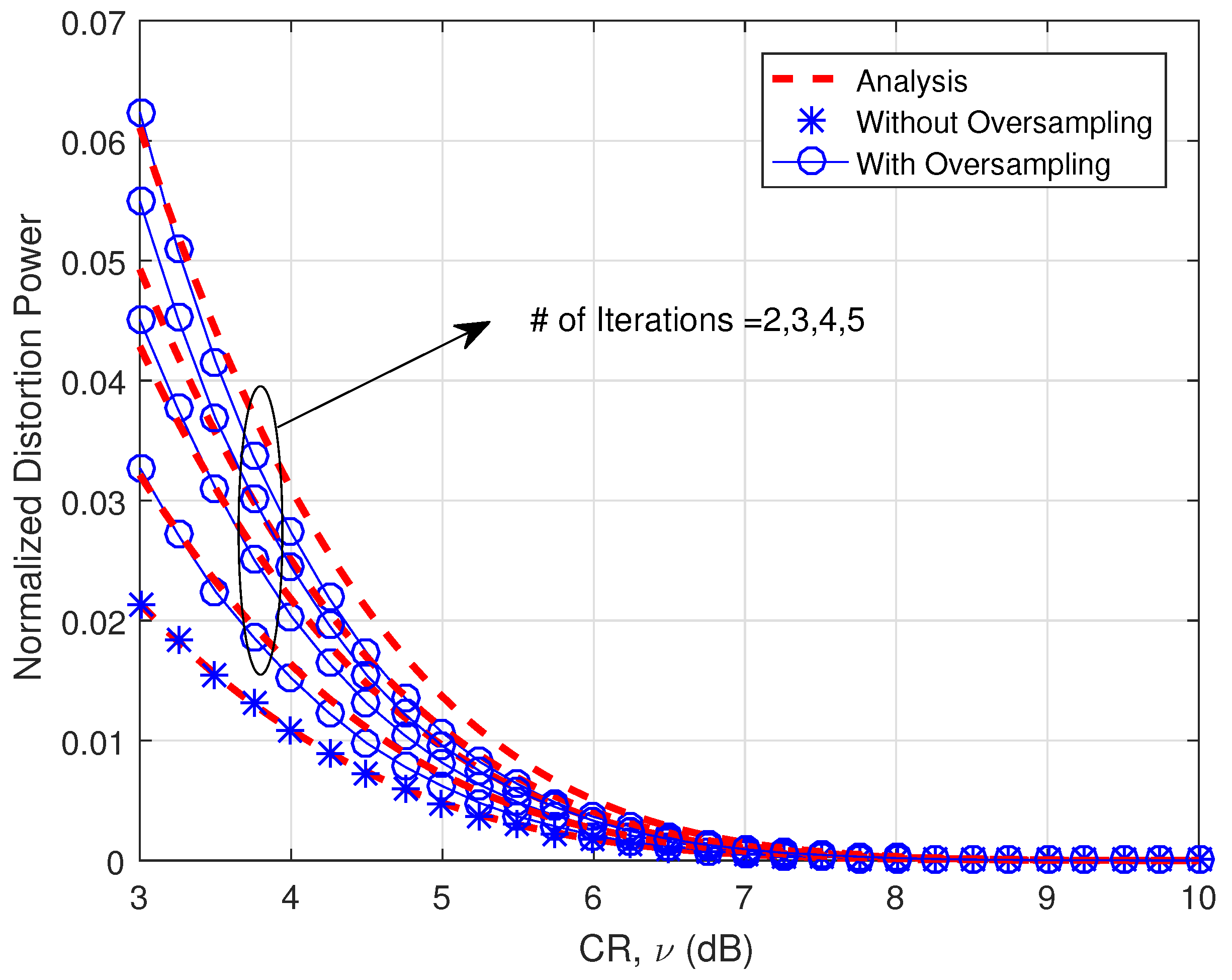
Now, we present an analysis of the effective SINR. Before showing the effective SINR, the clipping distortion noise should be investigated. We proposed a new normalized distortion power model in Equation (15), and we give a comparison of the simulation and analysis to show the validity of the proposed model in Figure 4.
The red lines indicate the analytical results, and the blue lines indicate the results of simulation. In the case without oversampling, the analytical result exactly matches the results of simulation. However, this case is meaningless in a real situation. As the number of iterations increases, the clipping distortion power also increases. We use the adjustable factors in Table 3 for the analytical results. Table 3 shows the relationship between and the number of iterations, Iter. Without oversampling, and Equation (15) with this value is well-matched with the simulation result. However, with oversampling, , and increases as the number of iterations increases. This is due to the fact that, as Iter increases, the distortion power also increases. Adopting adjustable factor in the nonlinear process is very general, and the approximation of the oversampled complementary comulative distribution function (CCDF) also has been successfully applied [44].
As observed, the analytical results are well-matched with the simulation results. We set the number of iterations as 5 in the scheme to show the numerical analysis and validity. This number of iterations can be reduced in any kind of situation. The amount of peak-regrowth is also heavily dependent on the number of iterations. We assume that five number of iterations is reasonable as both latency and peak-regrowth view points. The reasonable number of iterations can be chosen based on real implement situations.
Figure 5 gives the effective SINR versus SNR (dB), and the analytical results are also well-matched with simulation results. In particular, when is above 4 dB, the analytic results more closely match the results of simulation, and this is a very desirable result because most practical systems use the above 4 dB as evidenced from the EVM requirement.
5. Numerical Results
In this section, the spectral efficiency (SE), PAPR, and BER performance are analyzed with various CRs via computer simulations. We use the LS-MU-MIMO-OFDM system with , .
Figure 6 shows the SE performance in terms of the SNR for various CRs, . For Figure 6, we use the equation below:
where is the scaling factor for the pilot overhead and guard interval [1]. As witnessed, a typical SINR of MF precoded LS-MIMO is around less than 10 dB, thus QPSK modulation is used. Even though MF precoded LS-MIMO has worse BER, it can achieve very high SE due to the multi-user characteristics. Forty UEs can receive the signal from 400 antennas coincidently. Thus, the SE per UE should be divided by 40 from Figure 6. When we use the clipping ratios, which are in the ellipse , there is little degradation in the SE performance. As shown in Figure 2 of the previous subsection, choosing higher than 6 dB means SCR is much higher than 20 dB; thus, in this case, there is almost no performance degradation. The curves in the ellipse accompany a little bit of the SE performance degradation. However, it can definitely improve the PAPR performance. In particular, the case of = 5 dB is included for both groups (ellipse and ), and this case can be a very good alternative to improve the PAPR with little loss in the SE. The curves in the ellipse may not be the region of interest. Even if they can improve PAPR significantly, the SE performance degradation is quite severe, and this cannot be compensated by increasing the effective transmit power with a large number of antennas. When = 3 dB, from Figure 2, the SCR becomes 10 dB, and it means that the clipping distortion is already almost the same level as the IUI. What we would like to say here is that there is a systematic logic in choosing the appropriate (dB) in the proposed scheme.
Figure 7 shows the BER performance based on various CR. Note that MF precoding with LS-MIMO is effective in a low SNR region. When we use the clipping ratios in the ellipse , there is little BER performance degradation. As we can see from Figure 2 of the previous subsection, choosing higher than 6 dB means SCR is higher than 20 dB. Thus, it obviously shows almost no performance degradation. The curves in the ellipse accompany a little degradation in the BER performance. However, it can definitely improve the PAPR performance. In particular, = 5 dB is included in both groups (ellipse and ), and it can be a very good alternative to improve the PAPR with little loss in the BER. The curves in the ellipse are not the region of interest. Even if they can improve PAPR significantly, the BER performance degradation is quite severe, and cannot be compensated by increasing the effective transmit power with a large number of antennas. When = 3 dB, from Figure 2, the SCR becomes 10 dB, which means that the clipping distortion is already almost on the same level with the IUI. Thus, the logic of operation using the BER criterion is the same as using the SE criterion.
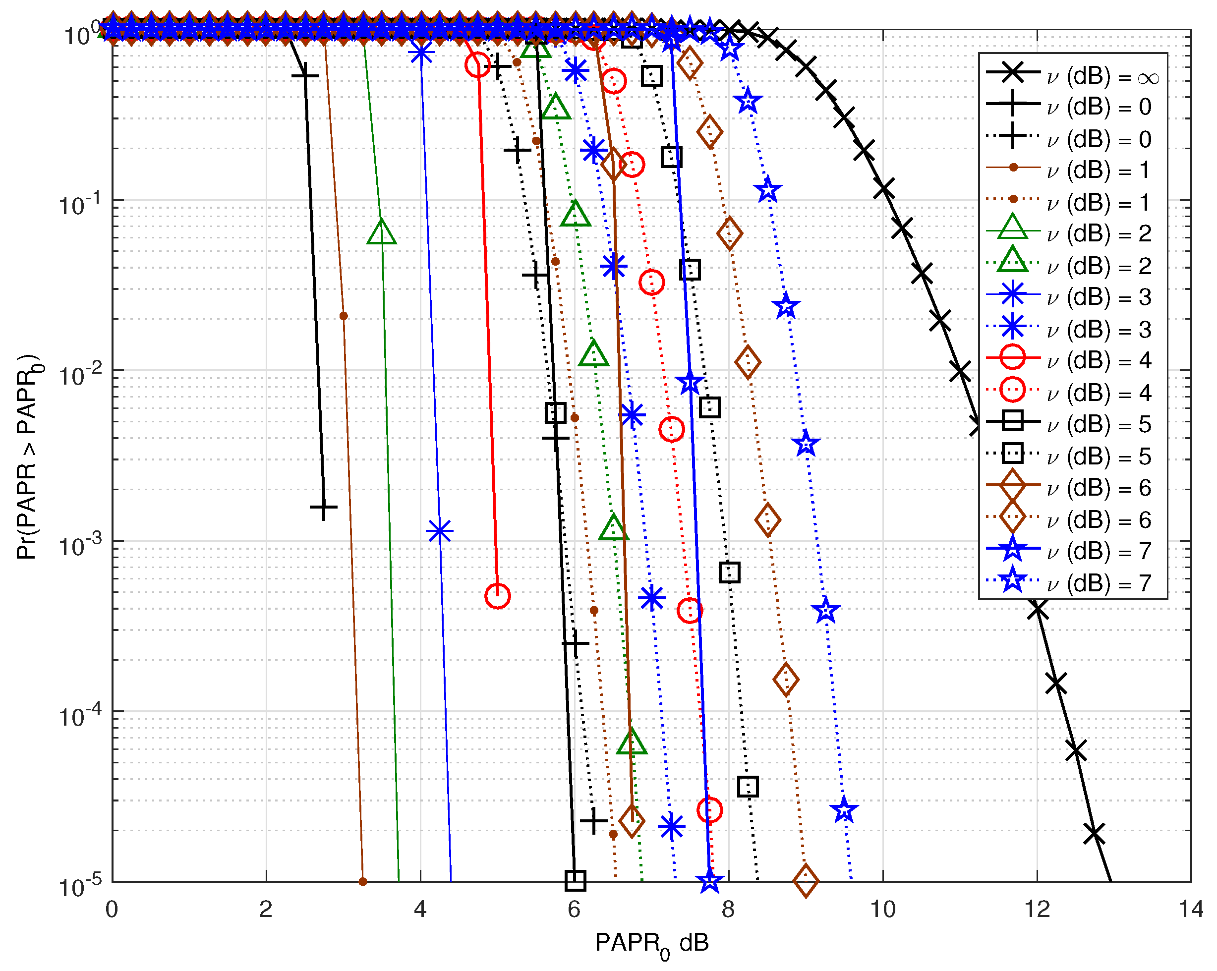
Figure 8 shows PAPR performance for various . When we choose complementary cumulative distribution function (CCDF) = , and = 4~5 dB, the amount of PAPR reduction is around 6–7 dB. This means that the proposed LS-MU-MIMO-OFDM clipping technique can significantly increase the PAPR performance with little SE performance loss. It is obvious that when the operating parameters/environment changes, the relevant also changes. However, the decision for would follow the same analysis we showed. Even though we only use the IUI in this paper, the proposed technique can use any kind of unavoidable interference in wireless communication environments, i.e., inter-cell interference, inter-frequency interference, etc. Since the environment always changes depending on situations, the proposed scheme should be used with an adaptive technique based on various related parameters. Basically, it shows that the proposed scheme can increase EE significantly in any wireless communication environments. The increase of EE is coming from the increase of the PA efficiency, which can be achieved from the efficient PAPR reduction using the proposed scheme.
6. Conclusions
In this paper, we have proposed an interference-aware iterative clipping and filtering PAPR reduction scheme for the LS-MU-MIMO-OFDM system. To deal with an LS-MIMO-OFDM system that has a large number of TX antennas, low complexity is one of the most important factors. Iterative clipping and filtering is a very powerful PAPR reduction technique for LS-MIMO-OFDM due to its simplicity and effectiveness. However, the clipping noise can be a serious problem because it can cause a performance degradation. We showed that the clipping noise can be buried in the IUI, if we carefully choose the CR depending on the IUI and/or channel condition. Then, we can improve the EE of the system with little performance penalty. Choosing the appropriate CR is very important and the appropriate CR can change depending on the situation. The adaptive choice of CR can be a great help. Comparing with other techniques which require high complexity and price, the proposed scheme can simply increase the EE. To validate the proposed scheme, we compared the SIR and SCR and determined the approximate range of CR, . Then, we analysed the normalized distortion power for the iterative clipping and filtering technique to derive the theoretical effective SINR. We presented various performances of the proposed scheme, SE, BER, and PAPR, and showed that the proposed scheme has very effective PAPR performance with little SE/BER performance loss. The proposed scheme can be a useful design method to increase the EE of the LS-MIMO-OFDM systems.
Acknowledgments
This work was supported by the National Research Foundation of Korea (NRF) grant funded by the Korea government (Ministry of Education) (NRF-2017R1D1A1B03028350), and faculty research fund of Sejong University in 2017. This work was conducted by the research Grant of Kwangwoon University in 2017.
Author Contributions
Byung Moo Lee designed the algorithm, performed the simulations, and prepared the manuscript. Youngok Kim was responsible for coordinating, writing, and revising the paper. Both authors discussed the results and approved the publication.
Conflicts of Interest
The authors declare no conflict of interest.
References
- Marzetta, T.L. Noncooperative Cellular Wireless with Unlimited Numbers of Base Station Antennas. IEEE Trans. Wirel. Commun. 2010, 9, 3590–3600. [Google Scholar] [CrossRef]
- Marzetta, T.L. Massive MIMO: An Introduction. Bell Labs Tech. J. 2015, 20, 11–22. [Google Scholar] [CrossRef]
- Björnson, E.; Larsson, E.G.; Marzetta, T.L. Massive MIMO: Ten myths and one critical question. IEEE Commun. Mag. 2016, 54, 114–123. [Google Scholar] [CrossRef]
- Nan, Y.; Sun, X.; Zhang, L. Joint channel estimation algorithm via weighted Homotopy for massive MIMO OFDM system. IEEE Trans. Wirel. Commun. 2016, 50, 34–42. [Google Scholar] [CrossRef]
- Lee, B.M.; Kim, Y. Design of an Energy Efficient Future Base Station with Large-Scale Antenna System. Energies 2016, 9, 1083. [Google Scholar] [CrossRef]
- Jeong, J.; Kim, H. On Optimal Cell Flashing for Reducing Delay and Saving Energy in Wireless Networks. Energies 2016, 9, 768. [Google Scholar] [CrossRef]
- Choi, H.-H.; Lee, J.-R. A Biologically-Inspired Power Control Algorithm for Energy-Efficient Cellular Networks. Energies 2016, 9, 161. [Google Scholar] [CrossRef]
- Chung, Y.-L. A Novel Algorithm for Efficient Downlink Packet Scheduling for Multiple-Component-Carrier Cellular Systems. Energies 2016, 9, 950. [Google Scholar] [CrossRef]
- Guariglia, E. Entropy and Fractal Antennas. Entropy 2016, 18, 84. [Google Scholar] [CrossRef]
- Ortigueira, M.D. Fractional Calculus for Scientists and Engineers; Springer: Dordrecht, The Netherlands, 2011. [Google Scholar]
- Guariglia, E.; Silvestrov, S. Fractional-Wavelet Analysis of Positive definite Distributions and Wavelets on D’(C). In Engineering Mathematics II; Silvestrov, S.D., Rancic, M., Eds.; Springer: Cham, Switzerland, 2017; pp. 337–353. [Google Scholar]
- Guariglia, E.; Silvestrov, S. A functional equation for the Riemann zeta fractional derivative, American Institute of Physics. In Proceedings of the ICNPAA 2016 Mathematical Problems on Engineering, Aerospace and Sciences, La Rochelle, France, 5–8 July 2016. [Google Scholar]
- Deng, P. Real Time Software-Defined Adaptive MIMO Visible Light Communications; Wang, J.-Y., Ed.; Visible Light Communications; InTech: Rijeka, Croatia, 2017. [Google Scholar]
- Deng, P.; Kavehrad, M. Software Defined Adaptive MIMO Visible Light Communications after an Obstruction. In Proceedings of the Optical Fiber Communications Conference and Exhibition (OFC), Los Angeles, CA, USA, 19–23 March 2017. [Google Scholar]
- Azhar, A.H.; Tran, T.-A.; O’Brien, D. A Gigabit/s Indoor Wireless Transmission Using MIMO-OFDM Visible-Light Communications. IEEE Photon. Technol. Lett. 2013, 25, 171–174. [Google Scholar] [CrossRef]
- Deng, P.; Kavehrad, M. Adaptive Real-Time Software Defined MIMO Visible Light Communications using Spatial Multiplexing and Spatial Diversity. In Proceedings of the 2016 IEEE International Conference on Wireless for Space and Extreme Environments (WiSEE), Aachen, Germany, 26–28 September 2016. [Google Scholar]
- Lee, B.M.; de Figueiredo, R.J.P. Adaptive Predistorters for Linearization of High-Power Amplifiers in OFDM Wireless Communications. Circuits Syst. Signal Process. 2006, 25, 59–80. [Google Scholar] [CrossRef]
- Kahn, L.R. Single-sideband transmission by envelope elimination and restoration. Proc. IRF 1952, 40, 803–806. [Google Scholar] [CrossRef]
- Cripps, S.C. RF Power Amplifiers for Wireless Communications; Artech House: Norwood, MA, USA, 2002. [Google Scholar]
- Jiang, T.; Wu, Y. An Overview: Peak-to-Average Power Ratio Reduction Techniques for OFDM Signals. IEEE Trans. Broadcast. 2008, 54, 257–268. [Google Scholar] [CrossRef]
- Li, X.; Cimini, L.J., Jr. Effects of clipping and filtering on the performance of OFDM. IEEE Commun. Lett. 1998, 2, 131–133. [Google Scholar]
- Armstrong, J. Peak-to-average power reduction for OFDM by repeated clipping and frequency domain filtering. Electron. Lett. 2002, 38, 246–247. [Google Scholar] [CrossRef]
- Lee, B.M.; Kim, Y. An adaptive clipping and filtering technique for PAPR reduction of OFDM signals. Circuits Syst. Signal Process. 2013, 32, 1335–1349. [Google Scholar] [CrossRef]
- Le Goff, S.Y.; Al-Samahi, S.S.; Khoo, B.K.; Tsimenidis, C.C.; Sharif, B.S. Selected Mapping without Side Information for PAPR Reduction in OFDM. IEEE Trans. Wirel. Commun. 2009, 8, 3320–3325. [Google Scholar] [CrossRef]
- Jeon, H.-B.; No, J.-S.; Shin, D.-J. A Low-Complexity SLM Scheme Using Additive Mapping Sequences for PAPR Reduction of OFDM Signals. IEEE Trans. Broadcast. 2011, 57, 866–875. [Google Scholar] [CrossRef]
- Irukulapati, N.V.; Chakka, V.K.; Jain, A. SLM based PAPR reduction of OFDM signal using new phase sequence. Electron. Lett. 2009, 45, 1231–1232. [Google Scholar] [CrossRef]
- Muller, S.H.; Huber, J.B. OFDM with reduced peak-to-mean power ratio by optimum combination of partial transmit sequences. Electron. Lett. 1997, 33, 368–369. [Google Scholar] [CrossRef]
- Wang, L.; Liu, J. Cooperative PTS for PAPR reduction in MIMO-OFDM. Electron. Lett. 2011, 47, 351–352. [Google Scholar] [CrossRef]
- Krongold, B.S.; Jones, D.L. PAR reduction in OFDM via active constellation extension. IEEE Trans. Broadcast. 2003, 49, 258–268. [Google Scholar] [CrossRef]
- Kou, Y.J.; Lu, W.-S.; Antoniou, A. A New Peak-to-Average Power-Ratio Reduction Algorithm for OFDM Systems via Constellation Extension. IEEE Trans. Wirel. Commun. 2007, 6, 1823–1832. [Google Scholar] [CrossRef]
- Yu, P.; Jin, S. A Low Complexity Tone Reservation Scheme Based on Time-Domain Kernel Matrix for PAPR Reduction in OFDM Systems. IEEE Trans. Broadcast. 2015, 61, 710–716. [Google Scholar] [CrossRef]
- Jiang, T.; Zhu, G.X. Complement block coding for reduction in peak-to-average power ratio of OFDM signals. IEEE Commun. Mag. 2005, 43, S17–S22. [Google Scholar] [CrossRef]
- Aburakhia, S.A.; Badran, E.F.; Mohamed, D.A.E. Linear Companding Transform for the Reduction of Peak-to-Average Power Ratio of OFDM Signals. IEEE Trans. Broadcast. 2009, 55, 155–160. [Google Scholar] [CrossRef]
- Myung, H.G.; Lim, J.; Goodman, D.J. Single carrier FDMA for uplink wireless transmission. IEEE Veh. Technol. Mag. 2006, 1, 30–38. [Google Scholar] [CrossRef]
- Berardinelli, G.; Ruiz de Temino, L.A.; Frattasi, S.; Rahman, M.; Mogensen, P. OFDMA vs. SC-FDMA: Performance comparison in local area IMT-A scenarios. IEEE Wirel. Commun. 2008, 15, 64–72. [Google Scholar] [CrossRef]
- Lee, B.M.; de Figueiredo, R.J.P. MIMO-OFDM PAPR reduction by selected mapping using side information power allocation. Digit. Signal Process. 2010, 20, 462–471. [Google Scholar] [CrossRef]
- Tan, M.; Latinovic, Z.; Bar-Ness, Y. STBC MIMO-OFDM Peak-to-average power ratio reduction by corss-antenna rotation and inversion. IEEE Comm. Lett. 2005, 9, 592–594. [Google Scholar]
- Baek, M.; Kim, M.; You, Y.; Song, H. Semi-blind channel estimation and PAR reduction for MIMO-OFDM system with multiple antennas. IEEE Trans. Broadcast. 2004, 50, 414–424. [Google Scholar] [CrossRef]
- Beko, M.; Marikj, M.; Dinis, R.; Tuba, M. Peak-to-average power ratio reduction in multiple-input multiple-output orthogonal frequency-division multiple access systems using geodesic descent method. IET Commun. 2016, 10, 212–218. [Google Scholar] [CrossRef]
- Choi, L.-U.; Murch, R.D. A transmit preprocessing technique for multiuser MIMO systems using a decomposition approach. IEEE Trans. Wirel. Commun. 2004, 3, 20–24. [Google Scholar] [CrossRef]
- Jiang, Y.; Li, J.; Hager, W.W. Joint Transceiver Design for MIMO Communications Using Geometric Mean Decomposition. IEEE Trans. Signal Process. 2005, 53, 3791–3803. [Google Scholar] [CrossRef]
- O’Neil, R.; Lopes, L.N. Envelop variations and spectral splatter in clipped multicarrier signals. In Proceedings of the IEEE International Symposium on Personal, Indoor and Mobile Radio Communications (PIMRC ’95), Toronto, ON, Canada, 27–29 September 1995; Volume 1, pp. 71–75. [Google Scholar]
- Ochiai, H.; Imai, H. Performance of the Deliberate Clipping with Adaptive Symbol Selection for Strictly Band-Limited OFDM Systems. IEEE J. Sel. Areas Commun. 2000, 18, 2270–2277. [Google Scholar] [CrossRef]
- Van Nee, R.; de Wild, A. Reducing the peak-to-average power ratio of OFDM. In Proceedings of the IEEE Vehicular Technology Conference (VTC98), Ottawa, ON, Canada, 21 May 1998; pp. 2072–2076. [Google Scholar]
Figure 1.
Signal-to-interference ratio as a function of and U. As increasing or reducing U, the signal-to-inference radio becomes higher.
Figure 1.
Signal-to-interference ratio as a function of and U. As increasing or reducing U, the signal-to-inference radio becomes higher.
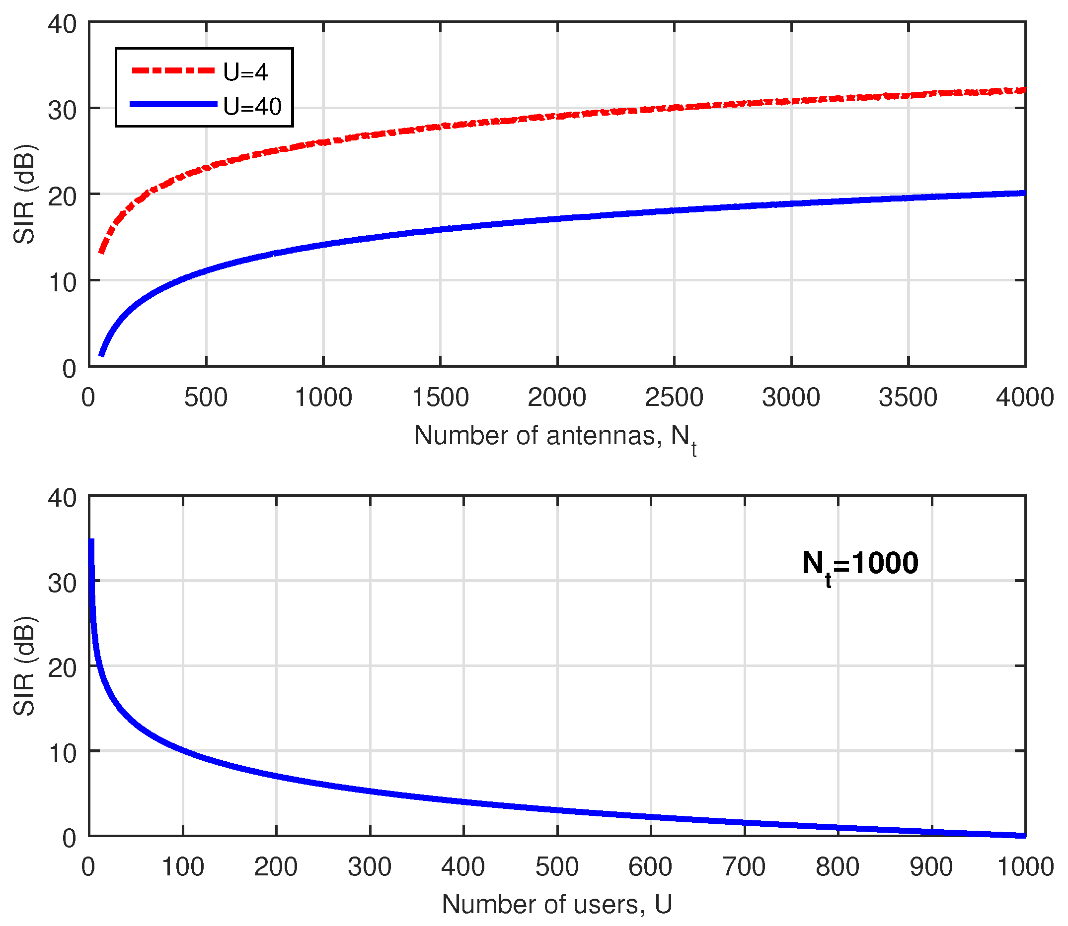
Figure 2.
Signal-to-clipping distortion radio (SCR) and error vector magnitude (EVM) as increasing clipping ratio, . The dotted line indicates the case of no iteration, and the solid line indicates the case of Iter = 5.
Figure 2.
Signal-to-clipping distortion radio (SCR) and error vector magnitude (EVM) as increasing clipping ratio, . The dotted line indicates the case of no iteration, and the solid line indicates the case of Iter = 5.
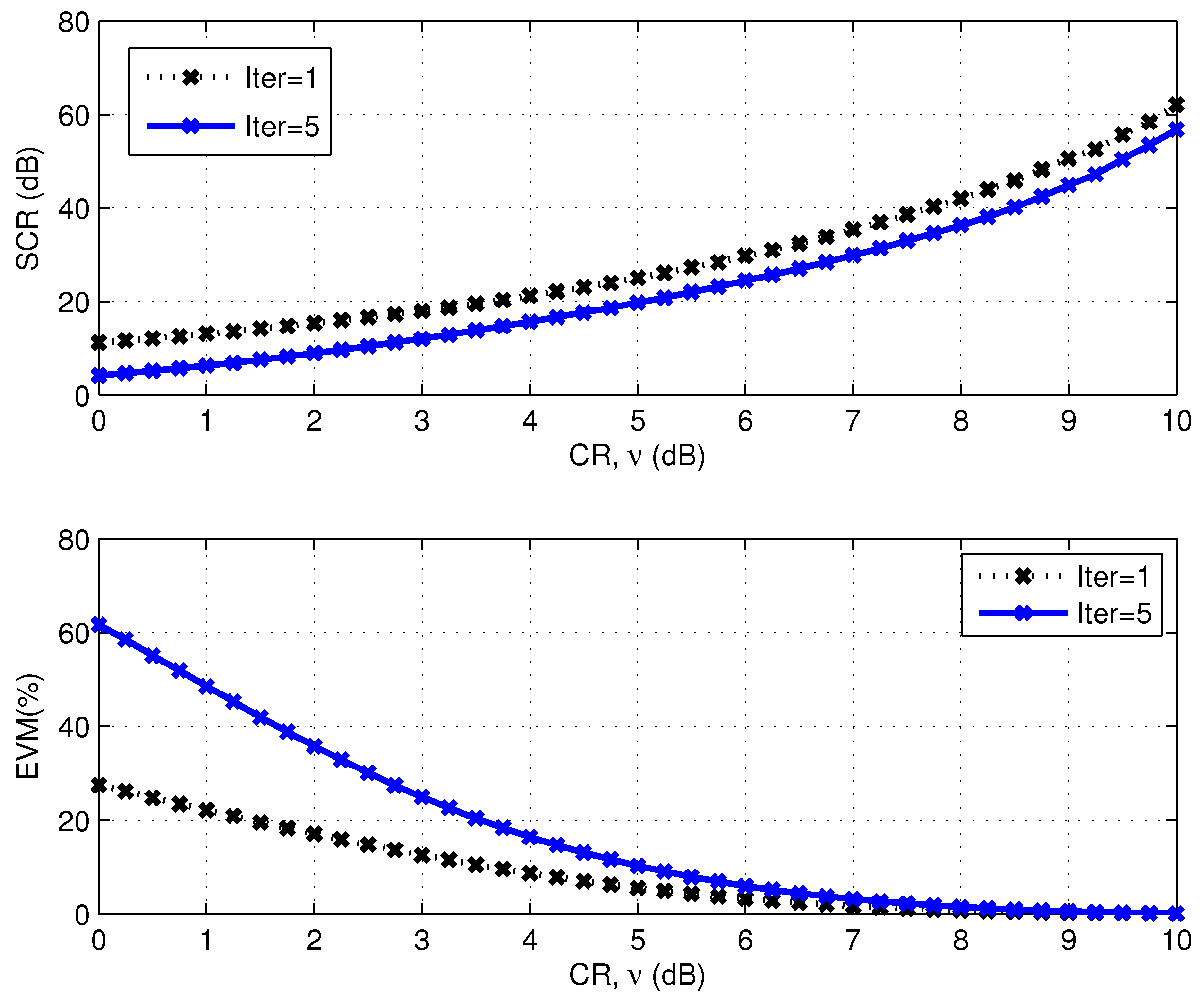
Figure 3.
Visualized example of inter-user interference and clipping distortion level (, ).
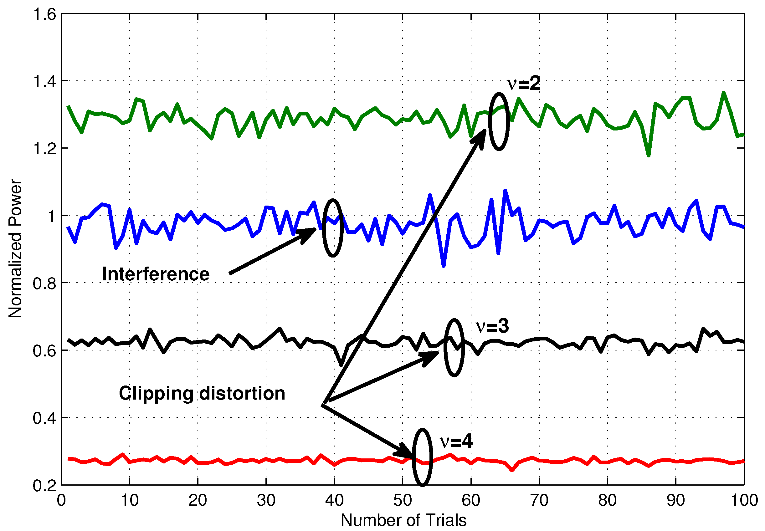
Figure 4.
Normalized distortion power versus clipping ratio (CR), (dB).

Figure 5.
The effective SINR versus SNR (dB), when Iter = 5.
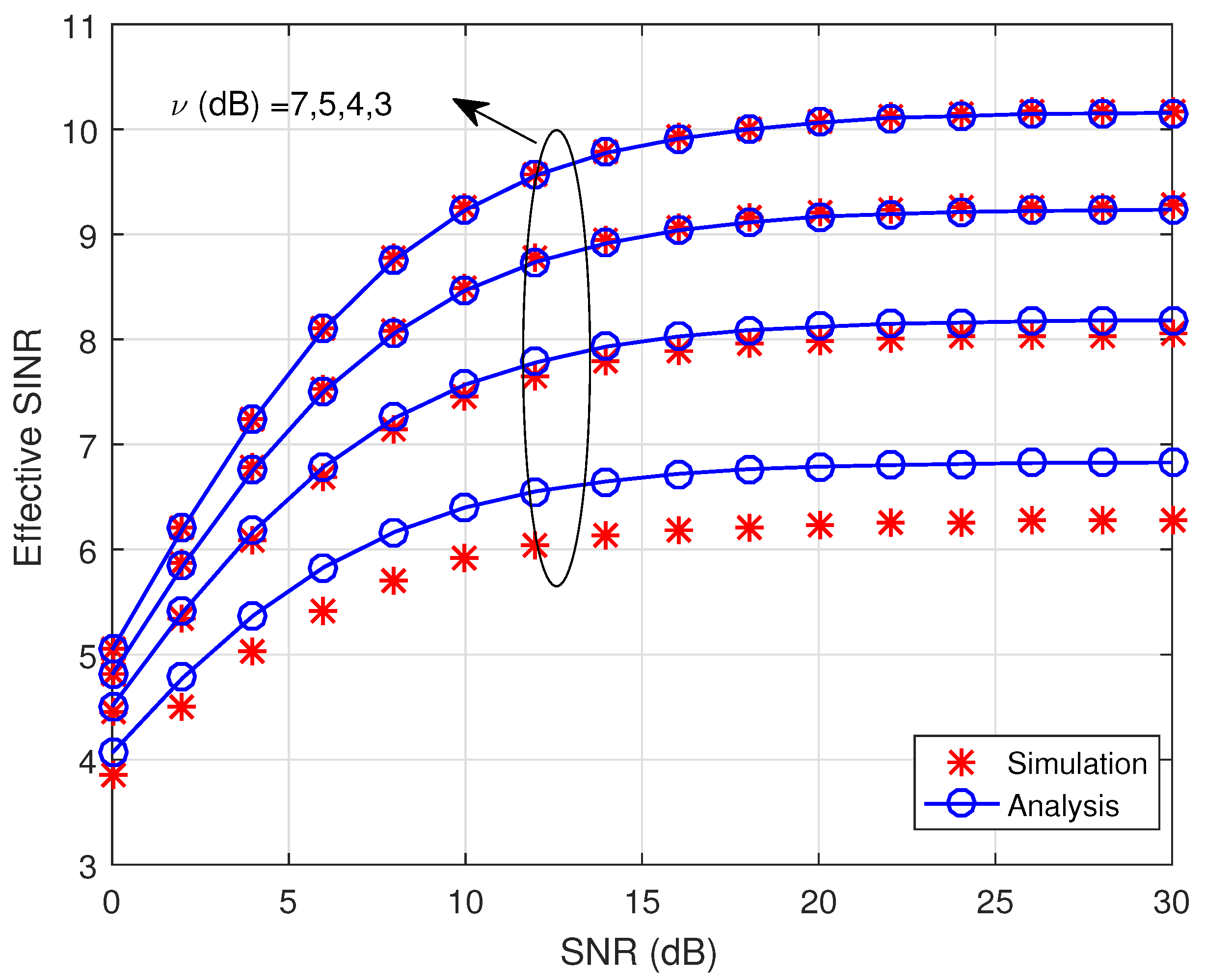
Figure 6.
SE performance ( = 400, U = 40) based on various CR, . The ellipse includes , the ellipse includes , the ellipse includes .
Figure 6.
SE performance ( = 400, U = 40) based on various CR, . The ellipse includes , the ellipse includes , the ellipse includes .
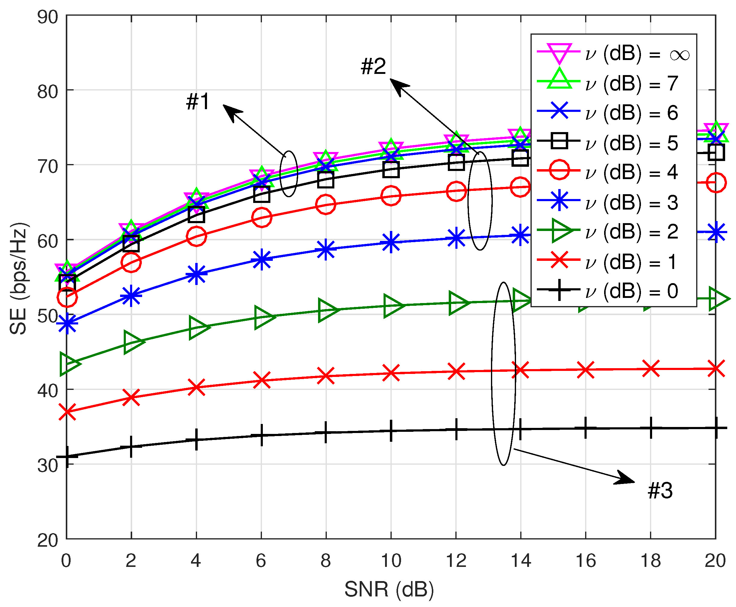
Figure 7.
BER performance ( = 400, U = 40) based on various CR, . The ellipse includes , the ellipse includes , the ellipse includes .
Figure 7.
BER performance ( = 400, U = 40) based on various CR, . The ellipse includes , the ellipse includes , the ellipse includes .
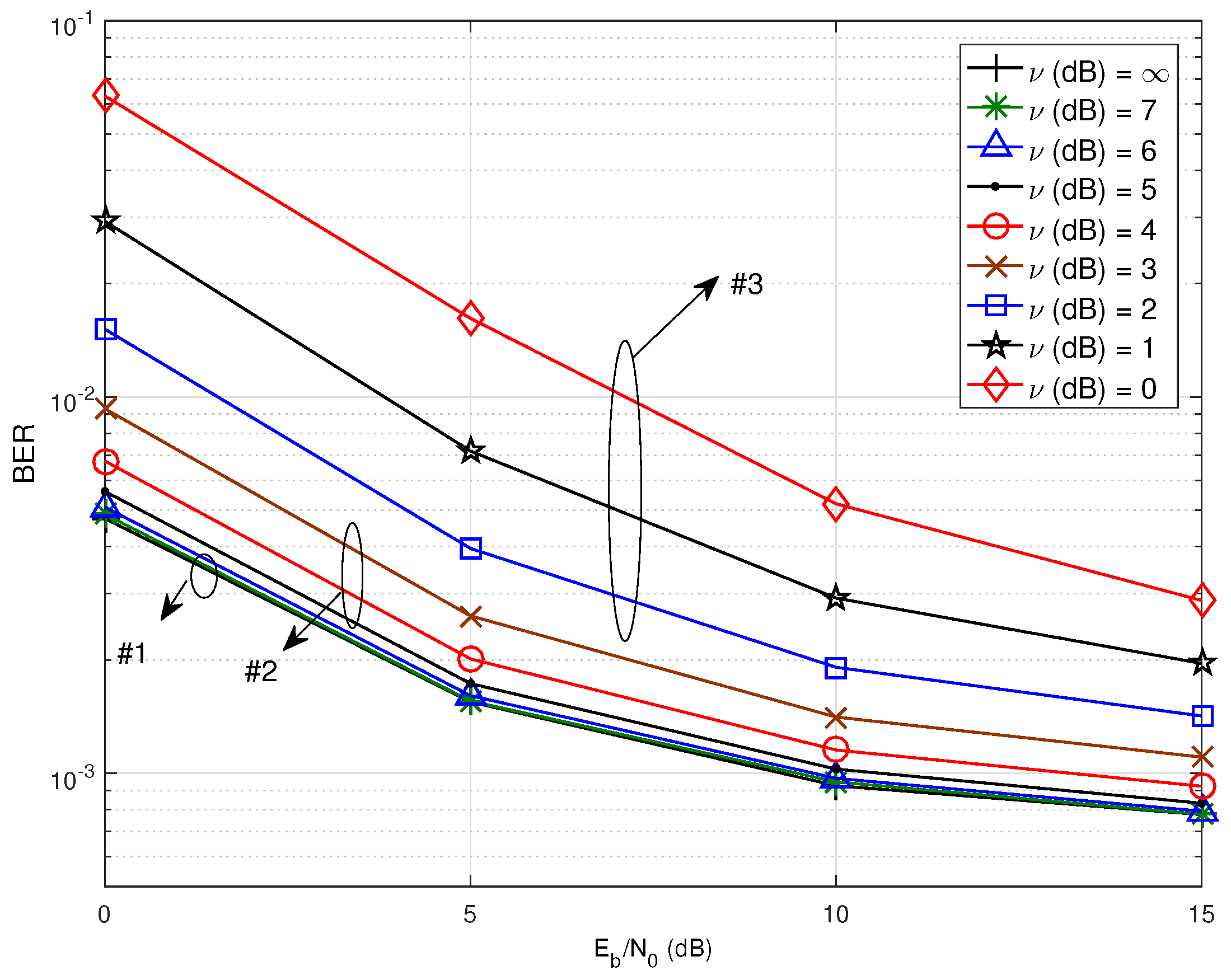
Figure 8.
PAPR performance of various . The dotted line stands for no iteration, the solid line stands for Iter = 5.
Figure 8.
PAPR performance of various . The dotted line stands for no iteration, the solid line stands for Iter = 5.

Table 1.
System parameters.
| Parameter | Description | Value |
|---|---|---|
| Slot length | 0.5 ms | |
| Pilot length in one slot | 0.214 ms | |
| Symbol duration | 71.4 us | |
| Guard Interval (GI) | 4.7 us | |
| Symbol without GI | 66.7 us | |
| Delay spread | 4.7 us |
Table 2.
An Example of a Look-UP Table (LUT) to determine .
| 50 | 0.7352 | 3 | 0.0619 |
| 100 | 0.3852 | 4 | 0.0270 |
| 200 | 0.1897 | 5 | 0.0108 |
| 300 | 0.1333 | 6 | 0.0038 |
| 400 | 0.0897 | 7 | 0.0009882 |
| 500 | 0.0776 | 8 | 0.0002922 |
| 600 | 0.0646 | 9 | 0.0000276 |
Table 3.
Adjustable factor, .
| Iter = 2 | Iter = 3 | Iter = 4 | Iter = 5 | |
|---|---|---|---|---|
| 1.5 | 2 | 2.3 | 2.85 |
© 2017 by the authors. Licensee MDPI, Basel, Switzerland. This article is an open access article distributed under the terms and conditions of the Creative Commons Attribution (CC BY) license (http://creativecommons.org/licenses/by/4.0/).
Share and Cite
MDPI and ACS Style
Lee, B.M.; Kim, Y. Interference-Aware PAPR Reduction Scheme to Increase the Energy Efficiency of Large-Scale MIMO-OFDM Systems. Energies 2017, 10, 1184. https://doi.org/10.3390/en10081184
AMA Style
Lee BM, Kim Y. Interference-Aware PAPR Reduction Scheme to Increase the Energy Efficiency of Large-Scale MIMO-OFDM Systems. Energies. 2017; 10(8):1184. https://doi.org/10.3390/en10081184
Chicago/Turabian StyleLee, Byung Moo, and Youngok Kim. 2017. "Interference-Aware PAPR Reduction Scheme to Increase the Energy Efficiency of Large-Scale MIMO-OFDM Systems" Energies 10, no. 8: 1184. https://doi.org/10.3390/en10081184
Note that from the first issue of 2016, this journal uses article numbers instead of page numbers. See further details here.