Article

Exploring PANI-TiN Nanoparticle Coatings in a PEFC Environment: Enhancing Corrosion Resistance and Conductivity of Stainless Steel Bipolar Plates

Centre for Fuel Cells and their Fuels, Chemical Engineering, University of Birmingham, Birmingham B15 2TT, UK
*
Author to whom correspondence should be addressed.
Energies 2017, 10(8), 1152; https://doi.org/10.3390/en10081152
Submission received: 4 July 2017 / Revised: 27 July 2017 / Accepted: 1 August 2017 / Published: 7 August 2017
(This article belongs to the Section D: Energy Storage and Application)

Abstract

:
Electrochemically-deposited polymer-metal composites, although explored for various uses, have only recently attracted attention for metallic bipolar plates used in fuel cells. Utilising a facile electrochemical deposition process, composite polyaniline and titanium nitride nanoparticle (PANI-TiN) coatings of varying thickness (5–50 cyclic voltammetry cycles) and composition (TiN nanoparticle concentration, 0.1 g L−1 and 0.5 g L−1) were deposited on stainless steel 304L (SS304) substrates. As compared to the pristine PANI coatings, which displayed an interfacial contact resistance (ICR) value of 367.5 mΩ cm2 and corrosion resistance (Ecorr) of 214 mVSHE, the composite PANI-TiN0.5 coatings displayed significantly reduced ICR values of 32.6 mΩ cm2 while maintaining similar corrosion resistance. The superior properties of these thin (~10 nm) composite coatings with low TiN loading (0.05–0.1 mg cm−2) show potential for further improvement in ICR with the possible use of higher TiN (or slightly lower PANI) concentrations. The study also demonstrated an interesting dynamic between PANI and TiN simultaneous deposition where the concentration of TiN NPs negatively affects the deposition rate for PANI, allowing the deposition of even thinner PANI coatings and possibly enabling control over the composition of the composite coating. The TiN NPs not only impart better conductivity for use as bipolar plates but, at higher loading, also assist PANI in enhancing corrosion resistance. Even for the lowest number of coating cycles (five cycles), the PANI-TiN0.5 composite films showed a remarkable 48 mV shift towards more positive/higher corrosion potential (Ecorr = 5 mVSHE) with respect to PANI (Ecorr = −57 mVSHE). The coatings demonstrated a reduction in corrosion current density to values of ~0.5 µA cm−2 achieving beyond the DoE 2020 target of 1 µA cm−2.

1. Introduction

Tremendous efforts are being made on a worldwide scale to improve the commercial and economic viability of alternative energy systems, like polymer electrolyte fuel cells (PEFCs), to replace the conventional combustion engine in the automotive industry. Despite all efforts so far, PEFCs still suffer from barriers, such as cost, durability, and power density, which need to be overcome. Among the various multi-pronged approaches towards cost reduction in PEFCs is the use of less-expensive bipolar plates as they continue to be one of the most expensive components, apart from the Pt-based catalysts. The bipolar plates (BPPs) are responsible for the distribution of fuel and oxidants to the electrochemically-active surface at the anode and cathode. Replacing the traditional, bulky, and expensive-to-machine graphite BPPs, metallic BPPs (stainless steels, titanium), have attracted significant attention due to their light weight, ability to achieve higher power density, and ease of manufacturing and formability for use in the automotive industry. Moreover, the use of metallic plates enable increase in the volumetric power density of the stack, high electrical conductivity, superior mechanical properties, and gas impermeability, while reducing the complexity in comparison to the traditional graphite plates [1,2,3,4]. A variety of stainless steels (SS) have been explored extensively in the literature owing to their favourable properties [4,5,6]. Although SS show significantly higher electrical conductivity as compared to traditional graphite plates, there is potential for achieving better interfacial contact resistance (ICR) with the gas diffusion layer (GDL). Besides, the metallic BPPs are also more susceptible to corrosion (both at the anode and cathode) in the harsh PEFC environment [7,8,9,10]. The corrosion layer formed on the surface of BPP further increases the ICR, thereby reducing the performance of PEFC [11]. In addition, the corrosion of SS results in the release of metallic cations (Cr3+, Fe2+, and Ni2+), which are known to contaminate and accelerate the degradation of other PEFC components, such as the polymer membrane and the GDL, eventually leading to cell failure [12,13,14]. To enhance the compatibility of SS for PEFC BPPs, various metallic coatings have been studied via multiple coating methods, with the physical vapour deposition (PVD) method being the most widely explored process [11,15]. Apart from Au-based noble metal coatings, a variety of metallic coatings using d-block metals, along with nitride-based coatings, such as TiN and CrN, have been explored in recent years [16,17,18]. The use of titanium nitrides, which exhibit good corrosion resistance and low electrical resistance, has the potential to further minimise the coating costs as opposed to noble metals [19]. However, some studies have suggested that TiN coatings are susceptible to a high density of defects during growth and have straight boundaries allowing oxygen diffusion [20,21]. Moreover, the PVD and other plasma based coating techniques continue to be extremely expensive, which limits their economic viability [11,22]. Thus, there remains a pressing requirement to continue to explore other viable coating methods and combinations.
An alternative to metallic coatings is the use of conductive polymer coatings where polymers such as; polyaniline (PANI) and polypyrrole (PPy) are able to significantly enhance the corrosion resistance [23,24,25,26,27]. Earlier studies with polymer coatings were focussed on specific applications involving corrosion resistance only and did not address the ICR issue [27,28]. Nonetheless, the intrinsically low conductivity of these polymers limits their ability to deal with the ICR challenge specific to BPPs in the fuel cell industry. The electrochemical deposition process offers an inexpensive and easily scalable alternative for polymer coating development, along with other advantages, such as controllable surface morphology and coating thickness, which can be reduced down to tens of nanometres [29,30]. Electrochemically-deposited polymer and polymer-metal composite coatings have been explored for a variety of uses [27,28,29,30,31]. However, the use for depositing polymer-metal composites (such as PANI-TiO2 and PANI-AuNP) as electronically conducting, corrosion resistant coatings on metallic BPP for use in fuel cells have only recently gained attention and demonstrated promising results [32,33,34]. Such composite coatings combine the advantages of corrosion-tolerant polymers with conductive metallic coatings. These offer the advantages of reducing costs by (1) using cheaper electrochemical methods, and (2) minimising the use of expensive metals by using relatively small quantities of metals. The use of metallic nanoparticles (NP) in such coatings further reduces the amount of metal required while providing good conductivity.
In this study, composite coatings of PANI and TiN NPs (PANI-TiN) on SS304 were explored in order to further lower the costs of the coating deposition while retaining the ICR and enhanced corrosion resistance of polymer-metal composite coatings. While PANI-TiN composite is not new in the field of polymer composites, to the best of our knowledge it has never been specifically studied as a coating material for BPP nor tested for fuel cell-specific operating conditions and requirements. This study investigates the effect of (a) increase in coating thickness (i.e., increase in the CV coating cycles) and (b) the TiN NP loading via different coating solution compositions using a one-step coating process. The one-step process was intended to understand and study the effects of any possible interaction between PANI and TiN NPs along with the possible variation in the TiN vs. PANI deposition rate during the cyclic voltammetry-based coating process.

2. Experimental

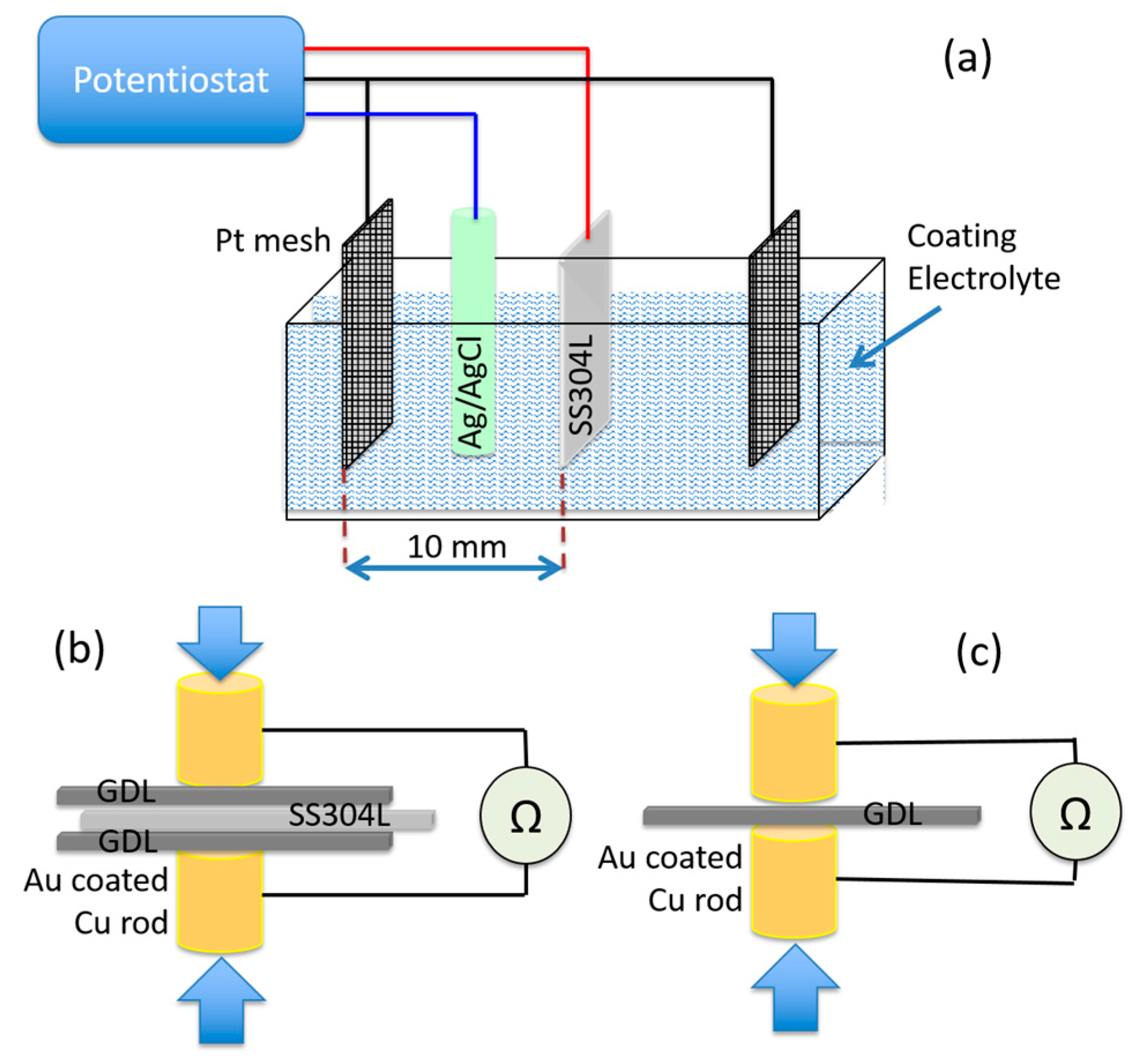
2.1. Preparation and Application of Coating

Stainless steel SS304 coupons of 35 × 35 mm2 area and 0.1 mm thickness are used in this study. Prior to any coating, the SS304 coupons are pre-treated by immersing in a solution of 50% H2SO4 acid for 15 min to clean and remove the passivation layer on the SS surface. The coupons are then rinsed in distilled water, dried under a nitrogen stream, and wiped with ethanol. Aniline monomer and TiN nanoparticles (average size 20 nm, as per manufacturer’s datasheet) were purchased from Sigma Aldrich (Gillingham, UK) and SkySpring Nanomaterials, Inc., (Houston, TX, USA) respectively. The particle size range was 10–30 nm and the SI shows the TEM image (S5) as provided by the manufacturer. The coating electrolyte consisting of variable concentrations of TiN NPs and aniline monomer (see Table 1) was prepared using ultrasonication with 0.1 M H2SO4 to allow the electropolymerisation of aniline. Electrochemical deposition was carried out in a three-electrode electrochemical cell with the SS coupon as the working, Pt mesh as the counter, and an Ag/AgCl as the reference electrode, respectively. Figure 1a displays the typical schematic of the coating/deposition setup.
The electrochemical coating cell was powered using an IVIUMSTAT potentiostat. The combined electropolymerisation of aniline and electrodeposition of TiN was performed using cyclic voltammetry (CV) scans in sweeping mode at a scan rate of 50 mV s−1 and a step potential of 5 mV with the potential window between −0.18 V and +1.00 VAg/AgCl. To achieve different coating thicknesses, variable numbers of CV cycles (5, 10, 20, and 50 cycles) were carried out.

2.2. Coating Characterisation

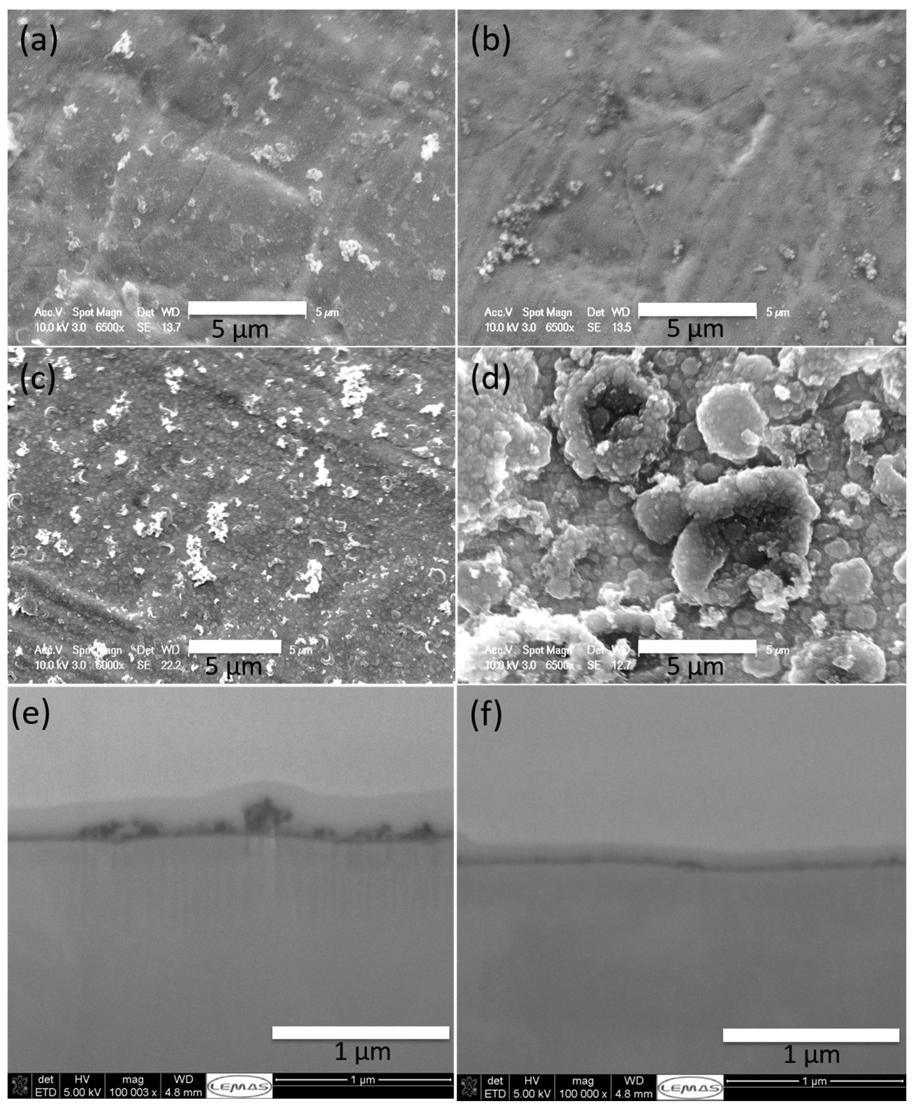
2.2.1. Coating Morphology and Composition

Fourier transform infrared spectroscopy (FTIR) was carried out to study the composition and confirm the polymerisation of aniline using a PerkinElmer Spectrum 100. Scanning electron microscopy (SEM) coupled with focussed ion beam etching (FIB-SEM) was performed at the LENNF facility, University of Leeds using the FEI Nova 200 NanoLab high-resolution field emission gun scanning electron microscope (FEGSEM) to study the morphology and thickness of the coating layer.

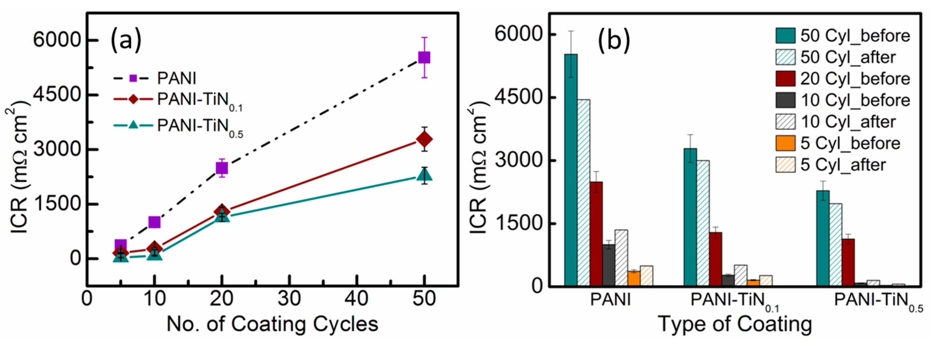
2.2.2. Interfacial Contact Resistance (ICR)

The ICR between the coated SS substrates and Freudenberg H2315 I2 C6 GDL was measured under compression of 140 N cm−2. The GDL samples were conditioned by cyclic compression three times before being used in the actual measurements in order to eliminate the effect of any irreversible behaviour from the GDL [34]. For ICR measurement, the coated substrate was placed between two GDLs and two gold-coated copper rods as shown in the schematic in Figure 1b. The resistance was measured using a four-wire Kelvin micro-ohmmeter (BS407 precision Milli/Micro-ohmmeter) under a compression force of 140 N cm−2 using an Instron 5848 MicroTester. The ICR value is then calculated using Equation (1):
ICR = ICRc+2xGDL − ICRGDL/2
where, ICRGDL/2 is the contact resistance between the GDL and the gold-coated rods, divided by 2 to obtain the resistance at each face (Figure 1c), and ICRc+2xGDL is the total resistance between the two gold-coated rods when SS coupon is placed as shown in 1b. This includes the contact resistance between the GDLs and the two faces of the SS coupon, through plane resistance between the GDL and the coupon, and the contact resistance of the GDL and gold-coated rods. Figure 1b,c shows the schematic of the ICR measurement setup.

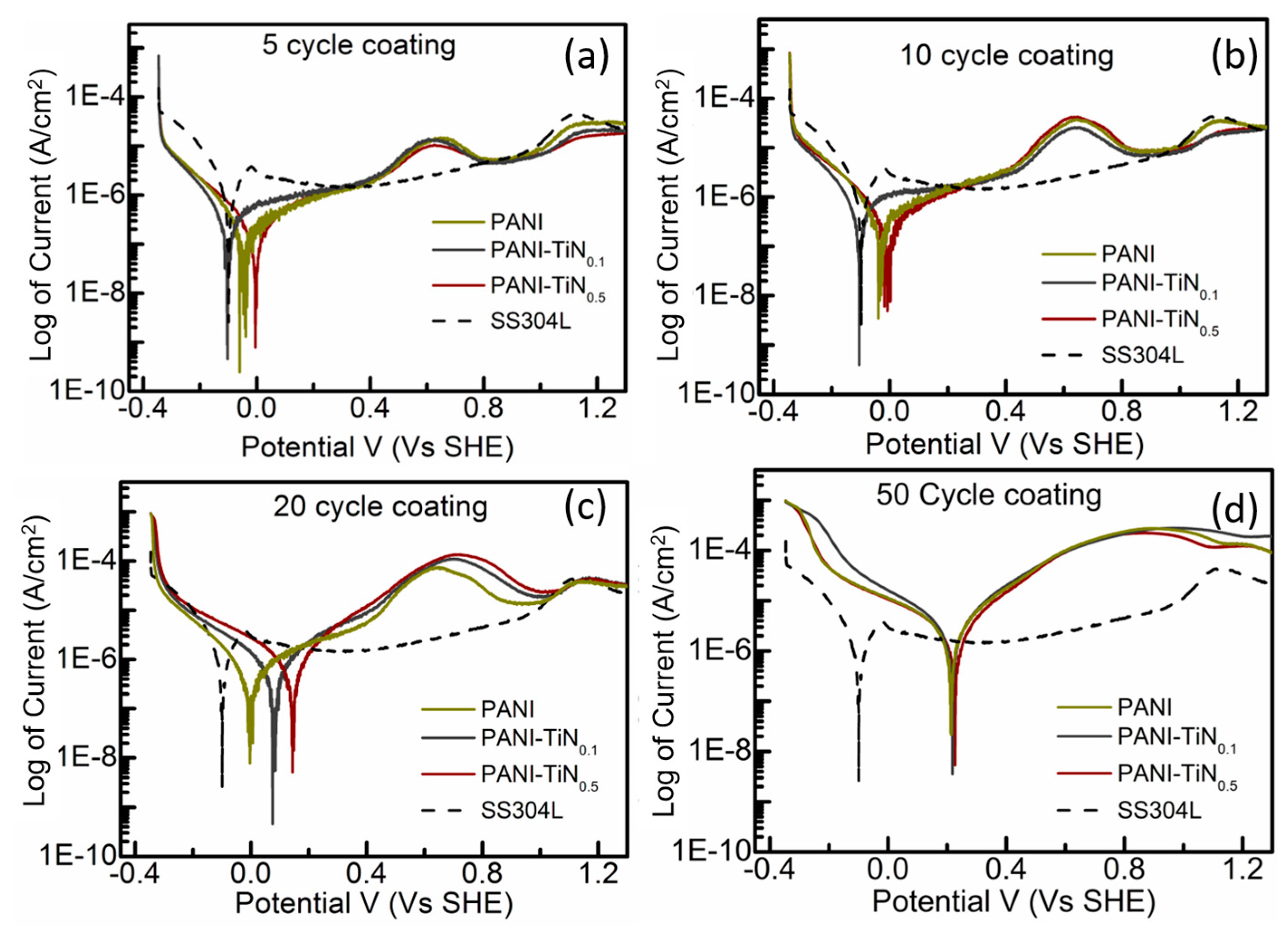
2.2.3. Electrochemical Corrosion

The corrosion resistance of the coatings was studied in a specially designed three-electrode electrochemical cell with the exposed working electrode area of 1 cm2. The coated SS304 sample, a platinum mesh and a mercury/mercury sulphate (Hg/Hg2SO4) electrode were connected as working, counter, and reference electrodes, respectively. The corrosion studies were conducted in a 1 mM H2SO4 electrolyte (pH = 3) at 80 °C. The Hg/Hg2SO4 was selected as the reference electrode for the corrosion studies instead of Ag/AgCl (which was used for electrochemical deposition) in order to avoid possible chloride contamination, which may occur over the long-term (Cl is a well-known contaminant, and can interfere with the corrosion process) and significantly enhance the corrosion rate.
Linear sweep voltammetry (LSV) was conducted in a nitrogen-saturated electrolyte in the potential range of −0.35 to 1.35 VSHE at a sweep rate of 1 mV s−1 to determine the corrosion potential. Potentiostatic corrosion testing was also conducted at 1.0 VSHE for 3 h in an oxygen-saturated solution to simulate the PEFC cathode environment at open circuit voltage. The corrosion current density was measured as an indication of the corrosion rate.

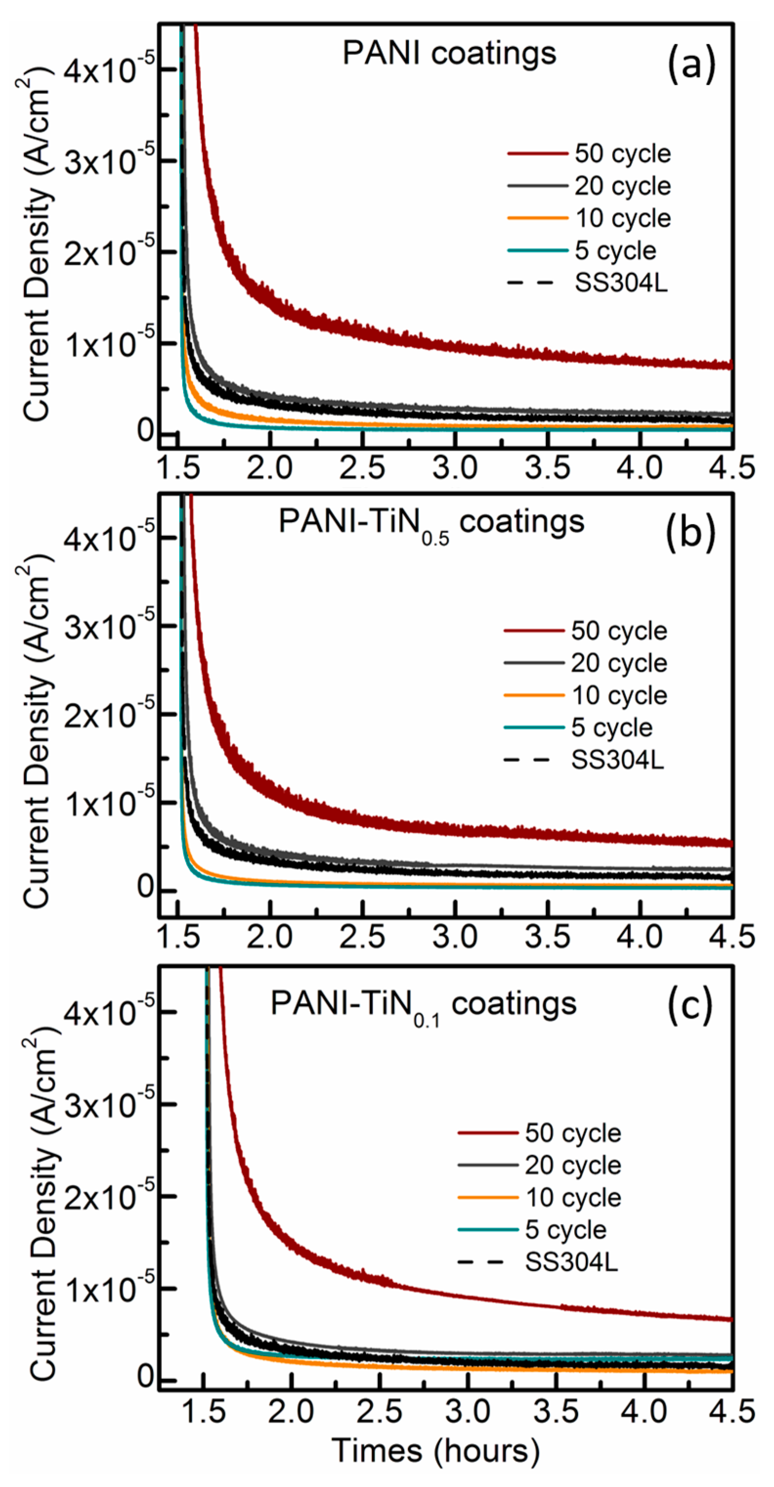
3. Results and Discussion

The various coatings on the SS304 substrates were achieved by the simultaneous electrochemical polymerisation and electrodeposition of PANI and TiN nanoparticles. The PANI coating thickness can be controlled using a number of parameters, such as aniline concentration, polymerising agent concentration and reaction time [32]. In the case of electrochemically-prepared coatings, the number of coating cycles is a crucial parameter for the control of film thickness [29]. In this study, two factors, namely, the number of cycles (5–50 coating cycles) and the coating solution composition were used to exercise control over the coating thickness and composition in order to tailor the properties of the PANI-TiN composite coatings. The CV curves for the electro-polymerisation of aniline in the PANI-TiN0.5 coating are shown in Figure S1.
Figure 2a–d show the SEM images of the four types of coatings prepared using the PANI-TiN0.5 coating solutions with increasing CV deposition cycles. While the TiN nanoparticles themselves are too small to be visible at the used magnifications, nevertheless, the evolution of PANI cluster/thickness can be clearly observed. These SEM images show the general trend for PANI evolution, which did not vary noticeably in the case of PANI-TiN as compared to PANI-only coatings. For the coatings obtained using 5 and 10 CV cycles (Figure 2a,b), a partially-covered surface, with areas of clusters of PANI fibres, is observed. At higher coating thickness, achieved with 20 and 50 CV cycles (Figure 2c,d), the SEM images identified more uniform surface coverage. Thicker coatings also appear to show a change in their microstructure, where the PANI clusters evolve to make a continuous thick, porous PANI structure, as shown in Figure 2d. This observation of porosity for thicker coatings is in agreement with other reports utilising electrochemical deposition [19,33,35]. For bipolar plate applications, thicker PANI coatings are unsuitable owing to the negative effect of thickness on electrical conductivity. Moreover, increased porosity in such thick, clustered PANI coatings is known to aid the path for the electrolyte through to the SS substrate, thereby accelerating substrate corrosion [33]. The effect of coating thickness and the need to minimise the porosity of PANI in the as prepared coatings, motivated the study of two different concentrations of TiN (with 0.1 and 0.5 g L−1 TiN) and understand the effect of variable TiN NP concentration on the ICR and corrosion properties of the composite coatings on SS304.

4. Effect of TiN NP Loading and Coating Thickness

High-resolution imaging using FIB-SEM was carried out to study the thickness of the composite coatings. The average coating thickness for 10 cycles of PANI-TiN0.1 and 10 cycles of PANI-TiN0.5 were found to be 15.04 nm and 9.38 nm, respectively. Furthermore, as seen in Figure 2e,f, underneath the sputtered Pt coating (standard sample preparation procedure for FIB etching), the composite TiN NPs and PANI clusters can be observed as a dark contrast. The ICR studies of the composite coatings prepared with 0.1 and 0.5 gL−1 TiN NPs mixed with 0.l M aniline in 0.1 M H2SO4 were compared with PANI coatings to study the effect of TiN on the electrical conductivity. This was also investigated with the variation in the number of CV coating cycles. Figure 3a shows the variation in the measured ICR values of the pristine PANI-, PANI-TiN0.1-, and PANI-TiN0.5-coated SS304 samples with respect to the increasing number of CV coating cycles in each case. As observed, for all the coatings, the ICR values were significantly affected by the number of coating cycles and especially for PANI coatings wherein the ICR seemed to be almost linearly dependant on the number of CV cycles for up to 20 coating cycles. As mentioned earlier, the expected increase in the ICR for PANI coated samples was due to the relatively low electrical conductivity of thicker PANI films as opposed to metals [36].
The addition of TiN NPs to the coating solution enabled a significant reduction in the resistance of the coated SS304 as the ICR values reduced tremendously for both sets of PANI-TiN coatings. In fact, for 5 cycle coatings, the ICR values of PANI-TiN0.1 and PANI-TiN0.5 were as low as ~156 and 32 mΩ cm2, respectively, as opposed to 367 mΩ cm2 for five cycle PANI coatings (see Table S1 for all recorded ICR values). It must be noted that the ICR value for PANI-TiN0.5 (32 mΩ cm2) coating with a coating thickness <10 nm (as seen from FIB-SEM Figure 2e,f) is a significant achievement in comparison to a recent report by Jin et al. [19], which achieved similar ICR values (10 mΩ cm2) with up to 200 nm thick TiN only coatings prepared using DC magnetron sputtering. Continuing the trend, for 10 cycle coating, the ICR for PANI reached nearly 1000 mΩ cm2 while PANI-TiN0.1 and PANI-TiN0.5 ICR values displayed dramatically improved values of 274 and 85 mΩ cm2, respectively. Figure S4 in the supporting information shows the ICR at lower coating cycles in a more appropriate scale. For the 20 and 50 cycle coatings, the PANI-TiN0.1 samples displayed 48% and 40% lower ICR, respectively, as compared to their PANI counterparts. The ICR value were further reduced for the PANI-TiN0.5 samples, wherein the ICR values for 50 cycle PANI-TiN0.5 coating was 30% lower than PANI-TiN0.1 and 58% lower than the PANI coatings. Both the variants of PANI-TiN coatings were also found to be more consistent allowing for better repeatability as seen from the smaller error bars in the Figure 3a. Interestingly, at 20 and 50 cycle coatings the difference in the ICR values for PANI-TiN0.5 and PANI-TiN0.1 was noticeably reduced (with PANI-TiN0.1 showing values ~1.2 times higher than PANI-TiN0.5) as opposed to those in 5 and 10 cycles where PANI-TiN0.5 displayed ICR values 4–5% lower than PANI-TiN0.1. This can possibly be ascribed to the reduction of TiN concentration in the coating solution leading to decrease in the rate of coating deposition [33].
It is important to note that the ICR value for uncoated SS304 after pre-treatment is within the range of 60–80 mΩ cm2. Clearly, all PANI-TiN coatings, apart from the 5 cycle PANI-TiN0.5 coatings, resulted in higher ICR values as compared to uncoated SS304. This, generally, highlights the PANI dominated electrical properties of the coatings. The lower ICR value of PANI-TiN0.5 coatings is attributed to thinner PANI coatings where the TiN NPs are able to overshadow the conductivity behaviour of PANI. As the PANI thickness increases further, even though the TiN NPs enable significant lowering of ICR, the PANI electrical properties remain dominant. It is well-known that metal NPs embedded in thin PANI coatings provide higher conductivity, as opposed to those in thicker PANI coatings, where the polymer dominates the electrical properties [33]. It is evident that the addition of TiN NP even in such small quantities leads to a significant enhancement in electrical conductivity. The authors also took the liberty of determining the maximum TiN NP loading in the composite coatings, calculated on the basis of a hypothetical overestimation that all TiN NPs were consumed during the electrochemical deposition process of 50 cycles. These can be seen in Table S2 and suggest maximum possible metal loading is still no more than 0.1 mg·cm−2 and 0.2 mg·cm−2 for 10 and 20 cycle PANI-TiN0.5 coatings, respectively. The actual values are expected to be much lower as the rate of electrochemical deposition is expected to decrease with decreasing TiN concentration in the coating solution with successive CV cycles [33]. However, these overestimated values are still significantly low in comparison to the amount of metal utilized and lost in processes such as PVD and sputter coating, which requires several hundred nanometres to micrometre thick metal coatings to achieve uniform coverage [19]. The composite polymer-metal coating using electrochemical deposition, thus significantly reduces the quantity of metals required to achieve the target ICR values.
Figure 3b compares the performance of the various coatings before and after being subjected to the corrosion studies. The actual performances of the coated samples in the potentiodynamic and potentiostatic corrosion tests have been discussed later. As a general trend (Figure 3b), the ICR values for all the 50 cycle coatings decreased after corrosion testing, with the PANI sample showing the maximum reduction of 19%. PANI has been reported to transform from conductive emeraldine salt to the less conductive emeraldine base form under the acidic testing conditions. Thus, the conductivity is actually expected to reduce if the oxidation state of PANI changes. As discussed earlier, the thicker PANI coatings are porous and filamentous in nature. During the acidic test conditions, it is expected that the poor adhesion of the PANI films to the underlying SS substrate will lead to significant loss of the PANI films into the test solution [27]. Consequently, for thicker coatings, the decrease in the ICR is attributed to the loss of coating during the corrosion test owing to poor adhesion (see Table S1). Thinner coatings with 5 and 10 cycle coatings showed an increase in ICR post-corrosion implying lesser tolerance towards corrosion. This is possibly due to (a) incomplete surface coverage leading to the formation of an isolating passive layer under PANI coating, [27,37,38] and/or (b) the reduction of PANI from emeraldine salt to emeraldine base, which is more likely for thin PANI coatings as compared to the thicker coatings.
The effect of the hybrid coatings on the corrosion resistance of the samples was examined with the help of polarisation curves. Figure 4 shows the polarisation curves for the 5, 10, 20, and 50 cycle coatings of the two composite PANI-TiN coatings and the corresponding pristine PANI coatings. For comparison, the polarisation curve for the bare SS304 substrate (Ecorr = −0.10 VSHE) is also shown whose values were found to be consistent with those reported in the literature [39]. In general, all coated samples demonstrated polarisation curves with very similar profiles (additional oxidation peak at ~0.6 VSHE), which resemble the behavioural attributes of PANI [33]. It was also observed that the current density at the peak close to 0.6 VSHE, increases with the increase in coating cycles and thickness. Overall, the results show a clear shift in the corrosion potential for all coatings towards more positive potentials with the increase in coating thickness. However, this shift is accompanied by a slight increase in the current density. An interesting observation in Figure 4a was that of the PANI corrosion potential (−0.02 VSHE) in comparison to that previously reported (0.22 VSHE) by Kun et al. [33], which was lower in the 5 cycle PANI coating. The ICR behaviour of the two, however, is not very different from each other (393 mΩ cm2—Zhang et al. [33]; 367 mΩ cm2—this work). As all other coating conditions are identical in the two studies, this variation in corrosion behaviour is attributed to the difference in the substrate behaviour and roughness. The two studies use different types of SS, namely, 316L, (Zhang et al.) and 304 (this work). Clearly, from the current comparison, SS316L appears to be more corrosion resistant of the two grades of SS. This further highlights the importance of the choice of SS type for the BPP applications [40,41].
In the case of 5 and 10 cycle CV coatings (Figure 4a,b), the PANI-TiN0.1 displayed almost identical corrosion potential (Ecorr) as compared to bare SS304. Interestingly, the PANI coatings displayed higher Ecorr as compared to PANI-TiN0.1 in both cases. The higher loading of TiN NPs, in the case of PANI-TiN0.5 samples, appears to enhance the corrosion resistance by a further shift in Ecorr towards more positive potentials. One point worthy of discussion here is that, it was generally assumed during this study that the corrosion protection in these coatings is predominantly controlled by the PANI present in the composite, owing to very small amounts of TiN NPs. Consequently, it was expected that, for the same number of coating cycles, the coating corrosion behaviour for PANI-TiN0.5, PANI-TiN0.1, and PANI would be the same. This, however, is contradicted in the behaviour observed in Figure 4a–c. For the identical number of coating cycles, the higher corrosion resistance of PANI-TiN0.5, as compared to PANI-TiN0.1 and PANI, clearly suggests the contribution of TiN NP in corrosion protection. The lower Ecorr of PANI-TiN0.1 at low coating cycles could be due to TiN NPs possibly interfering with the rate of PANI deposition on the SS304 in the initial stages, thus resulting in lower Ecorr than PANI. The CV (Figure S1) and FTIR studies (Figure S2), as shown in the SI, do not reveal any interference of TiN NP in PANI polymerisation with no variation in the characteristic CV peak and FTIR peaks associated with PANI polymerisation. These, however, cannot provide information on the amount of PANI polymerised/deposited, which could possibly explain the low Ecorr in the above sample. Additionally, further detailed studies on this aspect are required in the future to gain more understanding. The FIB-SEM studies as discussed earlier (Figure 2e,f), also demonstrated the 10 cycle PANI-TiN0.1 coatings to be thicker than the 10 cycle PANI-TiN0.5 coating, which further suggests that the presence of higher TiN NP concentration decreases the PANI deposition rate on SS. This negative impact on corrosion resistance could be overcome in PANI-TiN0.5 coatings where a higher amount of TiN NP in the coating potentially compensates for the slower PANI deposition. At 20 cycle coatings, a noticeable shift towards higher potentials was observed for PANI-TiN0.1 samples, from −0.11 VSHE (at 10 cycles) to 0.074 VSHE, thereby, achieving higher Ecorr than PANI samples for the first time in this study. A significant shift in Ecorr was also observed for PANI-TiN0.5 samples (Ecorr = 0.14 VSHE), again suggesting TiN NPs contributing to corrosion resistance.
For the 50 cycle coatings, all coated samples displayed identical corrosion potentials (~0.22 VSHE). The significant shift in Ecorr for PANI coatings from 20 to 50 cycle coatings suggest dramatic morphological change in the deposited PANI coating as the cycles increase from 20 to 50, also evident in the SEM images exhibiting large clusters. The identical corrosion potential and profile for all three types of coatings may be attributed to the dominance of PANI behaviour over the TiN NPs in thicker coatings. The dominance of PANI could possibly be due to increase in PANI deposition rate with increasing PANI on the SS304 surface. Additionally, as TiN NPs seem to be interfering with the PANI polymerisation/deposition rate, the reduced TiN NPs concentration in the coating solution owing to their consumption, may also contribute to this dramatic increase in PANI deposition rate. This would eventually lead to similarly thick coatings of PANI on all samples. The corrosion potential for the coatings used in this study are summarised in Table 2.
To further understand the durability and stability of the coatings, potentiostatic corrosion current density was measured for a duration of over 3 h at 1.0 VSHE in an O2-saturated 1 mM H2SO4 solution to simulate the PEFC cathode environment at open circuit voltage (OCV) to investigate the degradation of the coated samples. As expected, all samples displayed a dramatic initial loss in the current density due to the re-formation of the passivation layer. Table 2 lists the corrosion current densities (jcorr) for all samples. In general, the thinner coatings (5–10 cycle coatings) lead to a decrease in the corrosion current density in comparison with bare stainless steel samples (Figure 5a–c). On the other hand, thicker coatings, especially the 50 cycle coatings, resulted in a significant increase in the corrosion current density. This increase in corrosion current density corresponds to the shift of the polarisation curve to higher current densities and can be explained by the increase in the corrosion surface area due to the porous structure of the PANI based coatings. The trend, as evident from Figure 5 and jcorr values in Table 2, highlights the decrease in the corrosion current density with increase in the TiN content suggesting that the penetration of the corrosive ions is further resisted by the composite [32]. The introduction of the conducting metal NPs into PANI is generally expected to enhance the electrical conductivity of PANI. However, this is not true for all metal NPs. Mostafaei et al. reported that the addition of conducting ZnO nanorods resulted in the electrical conductivity of the composite to be even lower than that of PANI. The reason for this behaviour is not completely understood [42]. Nevertheless, the current study with PANI and TiN NP was successful in demonstrating enhanced conductivity behaviour upon introduction of TiN NP into PANI. Interestingly, in the current study, the lowest ICR and corrosion current density values are demonstrated in coatings with the lowest PANI thickness and highest TiN loading. Thus, despite the incomplete coverage of the composite coating on the surface, the coating is showing a reduction in corrosion current density to values of ~0.5 µA cm−2, which is better than the DoE 2020 target of 1 µA cm−2 [43]. Table 3 compares the performance of PANI-TiN coated SS samples studied in this work with other TiN based coatings on SS reported in recent literature.

5. Conclusions

Different composite coatings consisting of polyaniline and titanium nitride nanoparticles (PANI-TiN) with variable TiN NP loadings were successfully deposited electrochemically on stainless steel (SS304) for application in bipolar plates for PEFCs. The effect of number of coating cycles and, hence, coating thickness and morphology, along with the role of TiN NPs concentration on the behaviour of electrochemical coatings were studied. Interfacial contact resistance (ICR) and corrosion behaviour studied for the coated samples revealed that the introduction of small amounts of TiN NPs into PANI coating enabled significant enhancement in the electrical conductivity thereby reducing the ICR values for the composite coatings. Simultaneously, the PANI component of the composite coatings allowed for the good corrosion resistance behaviour of PANI to continue, thereby providing a combined effect of low ICR and good corrosion resistance. Although the ICR values achieved in this work (32 mΩ cm2) are slightly higher than the set DOE target, the results show promising potential for a further decrease in ICR with the use of lower PANI and higher TiN NP concentrations in future studies. For lower TiN NP loadings (PANI-TiN0.1), enhanced corrosion behaviour with respect to PANI and uncoated SS304 was not seen until 20 cycle coatings. However, for higher concentrations of TiN NPs (PANI-TiN0.5) even 5 cycle coatings demonstrated noticeably enhanced corrosion potential values as compared to PANI-only coatings. At higher coating cycles TiN NPs also seem to contribute noticeably to the corrosion resistance behaviour. While the addition of TiN NPs led to significant enhancement in electrical conductivity of the coatings, the dominant PANI behaviour in thicker coatings of 50 CV cycles resulted in identical corrosion behaviour for the two composite coatings (PANI-TiN0.1 And PANI-TiN0.5) as compared to PANI only coatings. Thus, the TiN NPs not only impart better conductivity, thereby reducing ICR, but also assist PANI in enhancing corrosion resistance. While at lower concentrations of TiN NP, the corrosion behaviour of coating is mainly controlled by PANI, at higher loading of TiN NP (20 cycle and beyond), TiN also contributes to corrosion resistance. The coatings, however, are showing a reduction in corrosion current density to values of ~0.5 µA cm−2 achieving beyond the DoE 2020 target of 1 µA cm−2. SEM and FIB examination along with corrosion resistance studies revealed an interesting dynamic between PANI and TiN during the simultaneous deposition process where TiN NPs decrease the deposition rate for PANI, allowing the deposition of even thinner PANI coatings. Thus, the concentration of TiN NPs in the coating solution can significantly affect the composition, as well as the thickness (mainly dependant on the amount of PANI deposited) of the deposited coating by controlling the rate of PANI deposition.

Supplementary Materials

Supplementary Materials can be found at www.mdpi.com/1996-1073/10/8/1152/s1.

Acknowledgments

The research leading to these results has received funding from the European Union’s Seventh Framework Programme (FP7/2007-2013) for the Fuel Cells and Hydrogen Joint Technology Initiative under grant agreement no 303449 10. The authors would also like to acknowledge the support of our collaborators in the STAMPEM project (http://www.sintef.no/projectweb/stampem) for their support of the work and the LENNF facility at the University of Leeds for the FIB-SEM analysis. The authors appreciate the input provided by Ahmad El-Kharouf during the course of this work.

Author Contributions

S.S. proposed the research concept with inputs from G.G., D.G.S. and K.Z. The experimental analysis and manuscript preparation was a joint effort by all authors.

Conflicts of Interest

The authors declare no conflict of interest.

References

  1. André, J.; Antoni, L.; Petit, J.P. Corrosion resistance of stainless steel bipolar plates in a PEFC environment: A comprehensive study. Int. J. Hydrogen Energy 2010, 35, 3684–3697. [Google Scholar] [CrossRef]
  2. Makkus, R.C.; Janssen, A.H.H.; de Bruijn, F.A.; Mallant, R.K.A.M. Use of Stainless steel of cost competitive bipolar plates in the SPFC. J. Power Sources 2000, 86, 274–282. [Google Scholar] [CrossRef]
  3. Hermann, A.; Chaudhari, T.; Spagnol, P. Bipolar Plates for PEM Fuel Cells: A review. Int. J. Hydrogen Energy 2005, 30, 1297–1302. [Google Scholar] [CrossRef]
  4. Wang, H.; Sweikart, M.A.; Turner, J.A. Stainless steel as bipolar plate material for polymer electrolyte membrane fuel cell. J. Power Sources 2003, 115, 243–251. [Google Scholar] [CrossRef]
  5. Shanian, A.; Savadogo, O. TOPSIS multipla-criteria decision support analysis for selection of metal bipolar plates for polymer electrolyte fuel cell. J. Power Sources 2006, 159, 1095–1104. [Google Scholar] [CrossRef]
  6. Silva, R.F.; Franchi, D.; Leone, A.; Pilloni, L.; Masci, A.; Pozio, A. Surface conductivity and stability of metallic bipolar plate materials for polymer electrolyte fuel cells. Electrochim. Acta 2006, 51, 3592–3598. [Google Scholar] [CrossRef]
  7. Liang, C.-H.; Cao, C.H.; Huang, N.-B. Electrochemical behavior of 304 stainless steel with electrodeposited niobium as PEMFC bipolar plates. Int. J. Miner. Metall. Mater. 2012, 19, 328–332. [Google Scholar] [CrossRef]
  8. Chung, C.Y.; Chen, S.K.; Chiu, P.J.; Chang, M.H.; Hung, T.T.; Ko, T.H. Carbon film coated 304 stainless steel as PEMFC bipolar plate. J. Power Sources 2008, 176, 276–281. [Google Scholar] [CrossRef]
  9. Dur, E.; Core, O.N.; Koc, M. Experimental investigations on the corrosion resistance characteristics of coated metallic bipolar plates for PEMFC. Int. J. Hydrogen Energy 2011, 36, 7162–7173. [Google Scholar] [CrossRef]
  10. Wang, Y.; Northwood, D.O. Effects of O2 and H2 on the corrosion of SS316L metallic bipolar plate materials in simulated anode and cathode environments of PEM fuel cells. Electrochim. Acta 2007, 52, 6793–6798. [Google Scholar] [CrossRef]
  11. Antunes, R.A.; Oliveira, M.C.L.; Ett, G.; Ett, V. Corrosion of metal bipolar plates for PEM fuel cells: A review. Int. J. Hydrogen Energy 2010, 35, 3632–3647. [Google Scholar] [CrossRef]
  12. Tawfik, H.; Hung, Y.; Mahajan, D. Metal bipolar plates for PEM fuel cells: A review. J. Power Sources 2007, 163, 755–767. [Google Scholar] [CrossRef]
  13. El-kharouf, A.; Chandan, A.; Hattenberger, M.; Pollet, B.G. Proton exchange membrane fuel cells degradation and testing: Review. J. Energy Inst. 2012, 85, 188–200. [Google Scholar] [CrossRef]
  14. Pozio, A.; Silva, R.F.; De Francesco, M.; Giorgi, L. Nafion degradation in PEFCs from end plate iron contamination. Electrochim. Acta 2003, 48, 1543–1549. [Google Scholar] [CrossRef]
  15. Karimi, S.; Fraser, N.; Roberts, B.; Foulkes, F.R. A Review of Metallic Bipolar Plates for Proton Exchange Membrane Fuel Cells: Materials and Fabrication Methods. Adv. Mater. Sci. Eng. 2012, 2012, 828070. [Google Scholar] [CrossRef]
  16. Lee, S.H.; Kakati, N.; Maiti, J.; Jee, S.H.; Kalita, D.J.; Yoon, Y.S. Corrosion and electrical properties of CrN-, TiN coated 316L stainless steel used as bipolar plates for polymer electrolyte membrane fuel cells. Thin Solid Films 2013, 529, 374–379. [Google Scholar] [CrossRef]
  17. Nam, N.D.; Jo, D.S.; Kim, J.G.; Yoon, D.H. Transparent amorphous In-Ga-Zn-O thin film as function of various gas flows for TFT applications. Thin Solid Films 2011, 519, 4078–4081. [Google Scholar] [CrossRef]
  18. Tian, R.; Sun, J. Corrosion resistance and interfacial contact resistance of TiN coated 316L bipolar plates for proton exchange membrane fuel cells. Int. J. Hydrogen Energy 2011, 36, 6788–6794. [Google Scholar] [CrossRef]
  19. Jin, C.K.; Lee, K.H.; Kang, C.G. Performance and characteristics of titanium nitride, chromium nitride multi-coated stainless tell 304 bipolar plates fabricated through rubber forming process. Int. J. Hydrogen Energy 2015, 40, 6681–6688. [Google Scholar] [CrossRef]
  20. Asri, N.F.; Husaini, T.; Sulong, A.B.; Majlan, E.H.; Ramli, W.; Daud, W. Coating of stainless steel and titanium bipolar plates for anti-corrosion in PEMFC: A review. Int. J. Hydrogen Energy 2017, 42, 9135–9148. [Google Scholar] [CrossRef]
  21. Omrani, M.; Habibi, M.; Amrollahi, R.; Khosravi, A. Improvement of corrosion and electrical conductivity of 316L stainless steel as bipolar plate by TiN Nanoparticle implantation using plasma focus. Int. J. Hydrogen Energy 2012, 37, 14676–14686. [Google Scholar] [CrossRef]
  22. Heras, N.D.-L.; Roberts, E.P.L.; Langton, R.; Hodgson, D.R. A Review of Metal Separator plate Materials Suitable for Automotive PEM Fuel Cells. Energy Environ. Sci. 2009, 2, 206–214. [Google Scholar] [CrossRef]
  23. Bazzaoui, M.; Martins, J.I.; Bazzaoui, E.A.; Albourine, A.; Martins, L. Corrosion protection of stainless steel plates in fuel cell environment by conducting polymers. Mater. Corros. 2014, 65, 67–75. [Google Scholar] [CrossRef]
  24. Abu-Thabit, N.Y.; Makhlouf, A.S.H. Handbook of Smart Coatings for Materials Protection; Woodhead Publishing: Cambridge, UK, 2014; pp. 459–486. ISBN 978-0-85709-680-7. [Google Scholar]
  25. Ren, Y.J.; Zeng, C.L. Effect of conducting composite polypyrrole/polyanilie coatings on the corrosion resistance of type 304 Stainless steel for bipolar plates for proton exchange membrane fuel cells. J. Power Sources 2008, 182, 524–530. [Google Scholar] [CrossRef]
  26. Yavuz, A.G.; Gök, A. Preparation of TiO2/PANI composites in presence of surfactants and investigation of electrical properties. Synth. Met. 2007, 157, 235–242. [Google Scholar] [CrossRef]
  27. Joseph, S.; McClure, J.C.; Chianelli, R.; Pich, P.; Sebastian, P.J. Conducting polymer-coated stainless steel bipolar plates for proton exchange membrane fuel cells (PEMFC). Int. J. Hydrogen Energy 2005, 30, 1339–1344. [Google Scholar] [CrossRef]
  28. Lee, C.-H.; Lee, Y.-B.; Kim, K.-M.; Jeong, M.-G.; Lim, D.-S. Electrically contuctive polymer composite coating on aluminum for PEM fuel cell bipolar plates. Renew. Energy 2013, 54, 46–50. [Google Scholar] [CrossRef]
  29. Le, D.P.; Yoo, Y.H.; Kim, J.G.; Cho, S.M.; Son, Y.K. Corrosion characteristics of polyaniline coated 316L stainless steel in sulfuric acid containing fluoride. Corros. Sci. 2009, 51, 330–338. [Google Scholar] [CrossRef]
  30. Ghani, S.; Sharif, R.; Bashir, S.; Ashraf, A.; Shahzadi, S.; Zaidi, A.A.; Rafique, S.; Zafar, N.; Kamboh, A.H. Dye-sensitized solar cells with high performance electrodeposited gold/aniline composite counter electrodes. Mater. Sci. Semicond. Process. 2015, 31, 588–592. [Google Scholar] [CrossRef]
  31. Qiu, Y.; Gao, L. Novel Polyaniline/Titanium nitride Nanocomposites: Controlable structures and electrical/electrochemical properties. J. Phys. Chem. B 2005, 109, 19732–19740. [Google Scholar] [CrossRef] [PubMed]
  32. Abaci, S.; Nessark, B. Characterization and corrosion protection properties of composite material (PANI + TiO2) coatings on A304 stainless steel. J. Coat. Technol. Res. 2015, 12, 107–120. [Google Scholar] [CrossRef]
  33. Zhang, K.; Sharma, S. Site-Selective, Low-Loading, Au Nanoparticle—Polyaniline Hybrid Coatings with Enhanced Corrosion Resistance and Conductivity for Fuel Cells. ACS Sustain. Chem. Eng. 2017, 5, 277–286. [Google Scholar] [CrossRef]
  34. El-Kharouf, A.; Mason, T.J.; Brett, D.J.L.; Pollet, B.G. Ex-situ characterisation of gas diffusion layers of proton exchange membrane fuel cells. J. Power Sources 2012, 218, 393–404. [Google Scholar] [CrossRef]
  35. Nam, N.D.; Kim, J.G.; Lee, Y.J.; Son, Y.K. Effect of thermal treatment on the corrosion resistance of polyaniline in H2SO4-HF acid mixture solution. Corros. Sci. 2009, 51, 3007–3013. [Google Scholar] [CrossRef]
  36. Reda, S.M.; Al-Ghannam, S.M. Synthesis and Electrical Properties of Polyaniline Composite with Silver Nanoparticles. Adv. Mater. Phys. Chem. 2012, 2, 75–81. [Google Scholar] [CrossRef]
  37. Choi, H.S.; Han, D.H.; Hong, W.H.; Lee, J.J. (titanium, Chromium) nitride coatings for bipolar plate for polymer electrolyte fuel cell. J. Power Sources 2009, 189, 2. [Google Scholar] [CrossRef]
  38. Sathiyanarayanan, S.; Muthukrishnan, S.; Venkatachari, G.; Trivedi, D.C. Corrosion protection of steel by polyaniline pigmented paint coating. Prog. Org. Coat. 2005, 53, 297–301. [Google Scholar] [CrossRef]
  39. Yoon, W.; Huang, X.; Fazzino, P.; Reifsnider, K.L.; Akkaoui, M.A. Evaluation of coated metallic bipolar plates for polymer electrolyte fuel cells. J. Power Sources 2008, 179, 265–273. [Google Scholar] [CrossRef]
  40. André, J.; Antoni, L.; Petit, J.P.; De Vito, E.; Montani, A. Electrical contact resistance between stainlesss steel bipolar plates and carbon felt in PEFC: A comprehensive study. Int. J. Hydrogen Energy 2009, 34, 3125–3133. [Google Scholar] [CrossRef]
  41. Lee, S.-J.; Lai, J.-J.; Huang, C.-H. Stainless steel bipolar plates. J. Power Sources 2005, 145, 362–368. [Google Scholar] [CrossRef]
  42. Mostafaei, A.; Nasirpouri, F. Epoxy/polyaniline-ZnO nanorods hybrid nanocomposites coatings: Synthesis, characterisation and corrosion protection performance of conducting paints. Prog. Org. Coat. 2014, 77, 146–159. [Google Scholar] [CrossRef]
  43. Multi-Year Research, Development and Demostration Plan. Available online: https://energy.gov/sites/prod/files/2016/10/f33/fcto_myrdd_fuel_cells.pdf (accessed on 27 February 2017).
  44. Lin, M.T.; Wan, C.H.; Wu, W. Enhanced corrosion resistance of ss304 stainless steel and titanium coated with alternate layers of TiN and ZrN in a simulated O2 rich environment of a unitized regenerative fuel cell. Int. Electrochem. Sci. 2014, 9, 7832–7845. [Google Scholar]
  45. Nam, N.D.; Vaka, M.; Hung, N.T. Corrosion behaviour of TiN, TiAlN and TiAlSiN-coated 316L stainless steel in simulated proton exchange membrane fuel cell environment. J. Power Sources 2014, 268, 240–245. [Google Scholar] [CrossRef]
  46. Zhang, D.; Duan, L.; Guo, L.; Wang, Z.; Zhao, J.; Tuan, W.H.; Niihara, K. TiN-coated titanium as the bipolar plate for PEMFC by multi-arc ion plating. Int. J. Hydrogen Energy 2011, 36, 9155–9161. [Google Scholar] [CrossRef]
Figure 1. Schematic of (a) coating set up, (b) ICR measurement of SS coupon (ICRcoupon+2xGDL), and (c) ICR measurement of GDL (ICRGDL).
Energies 10 01152 g001
Figure 2. SEM images for PANI-TiN (0.5) with varied thickness; (a) five cycles, (b) 10 cycles, (c) 20 cycles, and (d) 50 cycles and FIB-SEM images for (e) 10 cycles PANI-TiN0.1 and (f) 10 cycles PANI-TiN0.5.
Energies 10 01152 g002
Figure 3. (a) ICR values of the three coatings with respect to increasing CV coating cycles, and (b) ICR values for the three types of coatings before and after corrosion tests.
Energies 10 01152 g003
Figure 4. Potentiodynamic polarisation curves recorded in 1 mM H2SO4 at 80 °C for (a) five cycle, (b) 10 cycle, (c) 20 cycle, and (d) 50 cycle coatings.
Energies 10 01152 g004
Figure 5. Potentiostatic corrosion profiles for (a) PANI (b) PANI-TiN0.5, and (c) PANI-TiN0.1 coatings with varied coating cycle thicknesses.
Energies 10 01152 g005
Table 1. Details of different coatings prepared using various electrolyte composition in 0.1 M H2SO4.
Coating CompositionAniline Concentration (M)TiN Concentration (g L−1)
Coating Type
PANI0.10
PANI-TiN (0.1)0.10.1
PANI-TiN (0.5)0.10.5
Table 2. The corrosion potentials and corrosion currents recorded at 1.0 VSHE for all coatings with changes in TiN loading and coating thickness.
No. of CV Cycles50 Cycles20 Cycles10 Cycles5 Cycles
Coating Type Ecorr
V
jcorr
μA cm−2
PD
jcorr
μA cm−2
PS
Ecorr
V
jcorr
μA cm−2
PD
jcorr
μA cm−2
PS
Ecorr
V
jcorr
μA cm−2
PD
jcorr
μA cm−2
PS
Ecorr
V
jcorr
μA cm−2
PD
jcorr
μA cm−2
PS
PANI0.2143.47.4−0.0030.662.3−0.0330.350.9−0.0570.300.5
PANI-TiN0.10.2183.396.60.0750.612.8−0.1060.770.7−0.1030.340.3
PANI-TiN0.50.2272.845.20.1440.602.40.0040.300.60.0050.290.4
PD: Potentiodynamic; PS: Potentiostatic.
Table 3. Comparison of the best ICR, Ecorr, and jcorr values of this work with those of other recently-reported studies on TiN-based coatings on stainless steel.
AttributeICR
(mΩ cm2)
Ecorr
(mV Vs SHE)
jcorr
(μA cm−2)
PD
jcorr
(μA cm−2)
PS
Ref.
Sample/Coating
Details Coating Method
SS304/TiN (200 nm)
DC magnetron sputtering
10423----[19]
SS304/ZrN/TiN
Cathodic arc evaporation PVD
--2790.68--[44]
SS316L/TiN (1.5 μm)
Cathodic arc plasma
--3070.7--[45]
SS316L/TiN (3 μm)
Multi-arc ion plating
30-56>12.4[18]
Ti/TiN (3 μm)
Mulit-arc ion plating
2.44240.0086--[46]
SS316L/TiN
Cathode arc ion plating
102642.52.7[16]
SS304/PANI-TiN (10–200 nm)
Electrochem. CV
32 *5–2270.29–2.80.4–5.2This study
PD—Potentiodynamic; PS—Potentiostatic; * 5 cycle PANi-TiN0.5.

