
Experimental Investigation of the Effect of Biodiesel Blends on a DI Diesel Engine’s Injection and Combustion


Laboratory of Thermodynamics and Thermal Engines, Department of Mechanical Engineering, University of Thessaly, Volos 38334, Greece
*
Author to whom correspondence should be addressed.
Energies 2017, 10(7), 970; https://doi.org/10.3390/en10070970
Submission received: 26 May 2017
/
Revised: 6 July 2017
/
Accepted: 7 July 2017
/
Published: 11 July 2017
(This article belongs to the Special Issue Automotive Engines Emissions and Control)
Abstract
:Differences in the evolution of combustion in a single cylinder, DI (direct injection) diesel engine fuelled by B20 were observed upon processing of the respective indicator diagrams. Aiming to further investigate the effects of biodiesel on the engine injection and combustion process, the injection characteristics of B0, B20, B40, B60, B80 and B100 were measured at low injection pressure and visualized at low and standard injection pressures. The fuel atomization characteristics were investigated in terms of mean droplet velocity, Sauter mean diameter, droplet velocity and diameter distributions by using a spray visualization system and Laser Doppler Velocimetry. The jet break-up characteristics are mainly influenced by the Weber number, which is lower for biodiesel, mainly due to its higher surface tension. Thus, Sauter mean diameter (SMD) of sprays with biodiesel blended-fuel is higher. Volume mean diameter (VMD) and arithmetic mean diameter (AMD) values also increase with blending ratio. Kinematic viscosity and surface tension become higher as the biodiesel blending ratio increases. The SMD, VMD and AMD of diesel and biodiesel blended fuels decreased with an increase in the axial distance from spray tip. Comparison of estimated fuel burning rates for 60,000 droplets’ samples points to a decrease in mean fuel burning rate for B20 and higher blends.
1. Introduction
Alternative fuels have been introduced and widely investigated during the last decades, as a promising response to air pollution and fossil fuel shortage issues. Bio-diesel is an alternative to conventional diesel due to its desirable attributes such as biodegradability and sustainability. The effects of biodiesel blends on the injection characteristics have been studied by other researchers [1,2]. The atomization characteristics of biodiesel fuel such as spray tip penetration and mean droplet size play an important role in engine performance and emission characteristics. Moreover, biodiesel blends have different physical properties [3] and their atomization characteristics [4,5] need to be further investigated. Ramadhas et al. [6] studied correlations between the physical properties of biodiesel blends and their combustion characteristics in conventional engines. To study the effect of the high viscosity of biodiesels on the spray characteristics, Lee and Park [7] compared the process of spray development between the conventional diesel and biodiesel blends using a common rail injection system. Their results indicated that the spray tip penetration increases with the increase in mixing ratio of the biodiesel because the biodiesel blends are more difficult to atomize in comparison to conventional diesel due to their higher surface tension. Agarwal et al. [8] investigated the effect of varying fuel injection pressure and injection timing on particle size distribution and spray characteristics in a single cylinder, common rail direct injection engine fueled with Karanja biodiesel blends. The results of spray tip penetration and spray area of biodiesel blends and diesel showed that higher injection pressure result in a longer spray tip penetration and larger spray area than that at lower injection pressures at same elapsed time after the start of injection. Even small changes in the physical properties of the fuels are known to modify the interfacial velocities and consequently the internal injected jets velocity profiles [9]. Furthermore, the use of biodiesel blends in modern engines interferes in a complex way with the fuel injectors, since the injection orifices in the nozzles are created by electro-erosion machining, (electrical discharge machining, EDM) to produce diameters of the order of 100 μm, with their leading edges rounded off by hydro-erosion machining [10].
In order to increase understanding of the effect of biodiesel blends on the combustion process in a conventional DI (direct injection) diesel engine, various biodiesel blends were tested in the following ways:
- Measurement of combustion process by analysis of engine indicator diagrams;
- Spray visualization at low and standard injection pressures by use of a laser sheet visualization system;
- Comparative measurements of atomization characteristics (mean droplet velocity, Sauter mean diameter (SMD), droplet velocity and diameter distributions) at low injection pressures by Laser Doppler Velocimetry.
The biodiesel employed in the tests was a FAME (fatty acid methyl ester) produced from 40% rapeseed oil, 30% soybean oil and 30% recycled cooking oils. It was mixed with diesel fuel to produce B0, B20, B40, B60, B80 and B100 blends.
2. Experimental Setup
A test matrix is presented in Table 1 to facilitate understanding of the study methodology. Two main experimental setups were employed: A single cylinder engine test bench (in-house construction) and a low injection pressure setup with Laser Doppler Velocimetry (TSI, Shoreview, MN, USA) equipment installed. The fuel blends studied in each test procedure is shown in Table 1 with the respective color code.
2.1. Engine Test Equipment and Procedure
The engine experiments were carried out on a Ruggerini RF91 (RF91 engine, Ruggerini Motori, Reggio Emilia, Italy), 477 cm3, naturally aspirated, air cooled, single cylinder direct injection diesel engine equipped with a SiC diesel particulate filter (Ibiden Co.Ltd., Ogaki, Japan). The engine is coupled to a single phase AC alternator (MS100LG by NSM SrI, Vicenza, Italy) with a maximum power of 6 kVA loaded with a set of 4 resistances with a maximum capacity of 1.5 kW for each resistance. The fuel injection system has a four-hole nozzle with hole diameter of 0.24 mm located near the combustion chamber center, with an opening pressure of 210 bar. In order to accurately monitor the generator’s behavior under different operating conditions, active output power measurements were conducted by means of Fluke 1735 three-phase power logger (Fluke, Everett, WA, USA) under several low, medium and high load engine operation points. The main engine and injection system specifications are summarized in Table 2 and Table 3, respectively.
For the measurement of in-cylinder pressure, (indicator diagram), a Kistler 6052B1 piezoelectric transducer (Kistler, Winterthur, Switzerland) is flush mounted to the cylinder head, close to the injector, and connected to a Kistler AG5044A charge amplifier (Kistler, Winterthur, Switzerland). The crankshaft position is measured using a digital shaft encoder. The engine test rig included other standard engine instrumentation such as K-type thermocouples, pressure transducer and an electronic balance for fuel consumption measurement. Data acquisition was carried out by means of a National Instruments PCI-6259 card (National Instruments, Austin, TX, USA), with maximum sample rate of 1.25 MSamples/s.
Data acquisition and combustion analysis were carried out using in-house, LabVIEW-based code and commercial engine simulation software respectively. Output from the analysis of consecutive engine cycles included peak engine cylinder pressure, values of indicated mean effective pressure (imep), percentage coefficient of variation of imep (%COVimep), average crank angle for ignition delay and burn duration. The COV of imep was used as criteria for combustion stability (cyclic stability). Combustion analysis of B0 to B40 fuels was carried out at 3 engine operating points: 2000 rpm/11.9 Nm, 2600 rpm/12.7 Nm, 3250 rpm/16.2 m. The total number of recorded engine cycles for each fuel and operation point ranged from 200 to 2000, depending on the engine operation point and fuel type. Four series of measurements were carried out at these points and the results were subjected to quality checks, to select good samples for statistical processing.
2.2. Diesel Spray Test Equipment and Experimental Procedure
The LDV system is based on an Ar-Ion laser [11], emitting a 514.5 nm wavelength beam, subsequently divided by a beam splitter, with a frequency shift of up to 40 ΜHz is created by a Bragg cell. The two beams were collimated and focused inside the injected fuel jet, to form the fringe pattern. Seeding particles were not used in the LDV experiments. The signal from the scattered light is collected using a photomultiplier and a frequency processor interfaced to a computer.
The experiments were conducted at room conditions. LDV measurements cannot directly measure droplet size distribution. However, TSI software [11] and in-house computations were employed to correlate droplet sizes with droplet velocities. Subsequently, estimated droplet size distributions were employed in estimating total fuel burning rate for the sample of 60,000 droplets employed. The effect of oxygenates was taken into account in this calculation. The most marked difference observed in the results is a decrease in the axial mean droplet velocity. To study the atomization characteristics of biodiesel fuels, it is necessary to analyze their SMD distributions because the physical properties such as surface tension and viscosity of the biodiesel are different from those of conventional diesel.
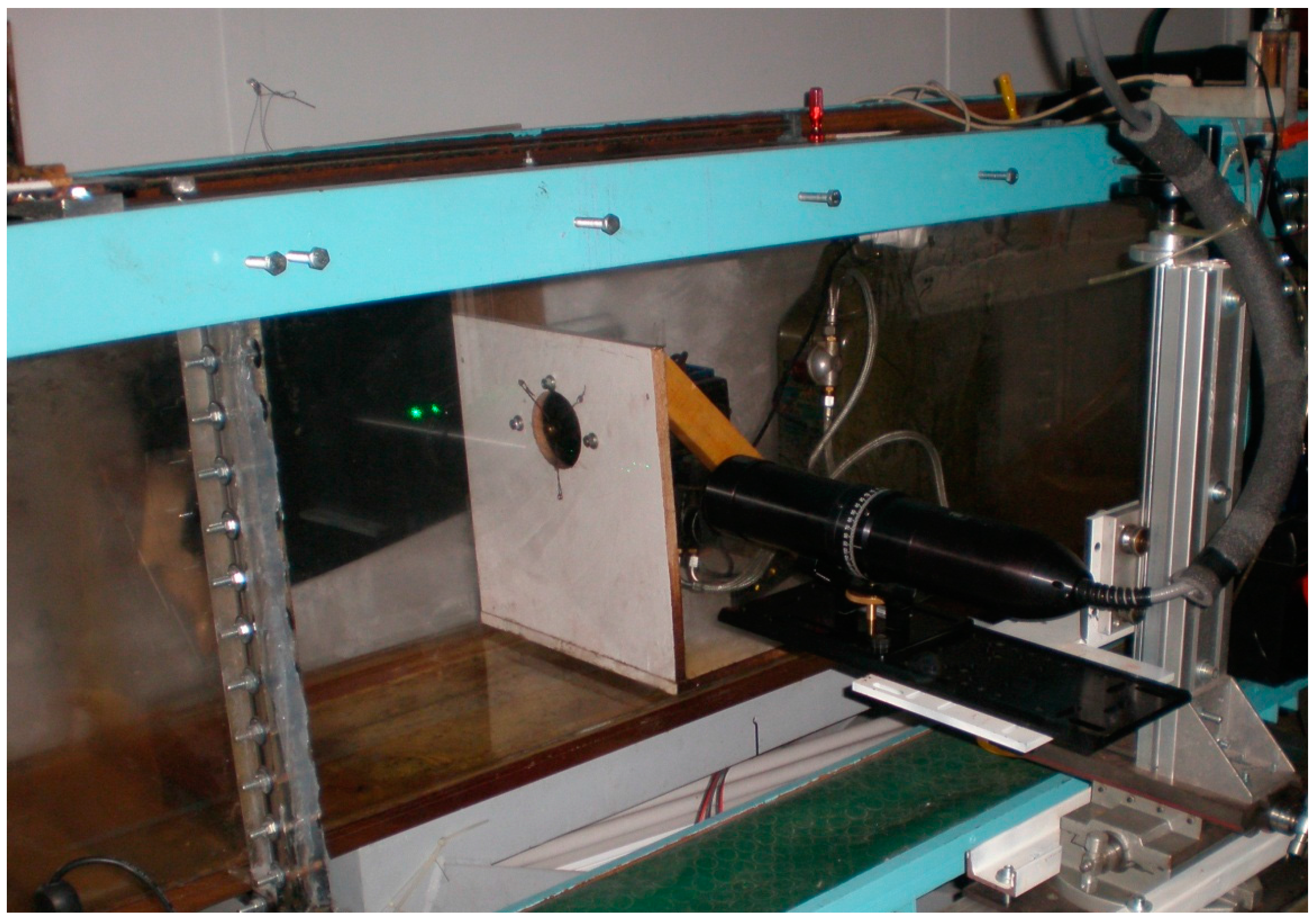
Fuel viscosity, density and surface tension affect the spray evolution. The spray analyzed in this work was generated by a manually controlled low pressure injection system, which consists of a modified diesel burner mounted inside a water tunnel. The experimental setup is presented in Figure 1. The test nozzle used in the experiments has one hole of 0.2 mm diameter and an 80° spray angle. The fuel pump was powered by an electric motor running at 2900 rpm and the fuel was pressurized to 10 bar. Figure 2 shows a schematic diagram of the injection velocity measuring system.
To investigate the atomization characteristics of biodiesel fuel, 26 measurement points were selected along the axis of injection, at 5 mm intervals from 10 mm to 223 mm from nozzle tip, and at 2 mm intervals to the radial direction. At each measurement point, 60,000 droplets were captured and analyzed by the LDV system.
The spray visualization system on the other hand, was composed of a La Vision laser with a rotating mirror, employed to produce a level light sheet. The characteristics of the Laser are Po (power) = 1.277 W, F (frequency) = 10,000 Hz and λ (wavelength) = 532 nm. The laser sheet crosses perpendicularly the lateral Plexiglas surface of the tunnel and lights up a vertical section of the fuel spray. Five points were selected for the visualization at 1, 2, 3, 5.5, 10.5 and 15.5 cm axial distance from nozzle tip. Three fuels were tested B0, B40 and B100. Figure 3 shows a schematic of the flow visualization technique employed. The experiments were conducted at room conditions, ambient temperature and pressure 25 °C and 1 atm, respectively.
2.3. Properties of Fuels and Blending
The fuels under investigation are commercial diesel fuel, pure biodiesel and four blends of biodiesel in diesel fuel. The volume based blending ratios of biodiesel with diesel fuel were set at 20%, 40%, 60%, 80% and 100% (pure biodiesel), throughout this work denoted as B0, B20, B40, B60 B80 and B100, respectively. B0 conforms to European standard EN 590. The biodiesel employed in the measurements is a fatty acid methyl ester produced by 40% rapeseed oil, 30% soybean oil and 30% recycled cooking oils. It conforms to EN 14214:2008 specifications [12]. The main specifications of the fuel blends are shown in Table 4.
3. Results and Discussion
3.1. Calculation of Injection Timing Advance
Tat and Van Gerpen [13] proposed a model to calculate the injection delay in a PLN (pump in line nozzle) system by evaluating differences in injection timing between conventional diesel and soy methyl ester in a John Deere 4276T engine running at 2100 rpm. According to their methodology, assessment of the injection timing advance with biodiesel takes two factors into account: faster pressure wave propagation due to higher speed of sound and faster pressure rise produced by the pump due to lower compressibility of biodiesel (higher bulk modulus). The rate of fuel pressure rise is related to the volume change produced by the injection pump plunger, the volume of compressed fluid and the fluid bulk modulus:
The rate of volume change produced by the injection pump plunger is given by:
where is the plunger velocity, Ap is the plunger cross section and Equation (1) takes the following form:
Assuming all variables in the right side of Equation (3) as constants the equation can be integrated to describe fuel pressure as a function of crank angle:
According to Equation (4), the crankshaft rotation required to reach the nozzle opening pressure (NOP) is:
The results of the calculated crankshaft rotations until the nozzle opening pressure for four fuel blends, namely, B0, B20, B40 and B100, are summarized in Table 5. Based on these results, it is obvious that the higher bulk modulus of biodiesel fuel leads to an injection timing advance of 0.22°, 0.42° and 1.1° for B20, B40 and B100, respectively.
In addition, the impact of the speed of sound should be taking into account for the total calculation of the injection timing advance.
The Ruggerini RF91 engine has a 0.4 m long injection line. If the fuel supplied to the engine is at 40 °C, the speed of sound for conventional diesel and rapeseed methyl ester are 1302 m/s and 1345 m/s respectively (at atmospheric pressure). A pressure wave moving through diesel fuel in the injection line will take 0.307 ms to propagate from pump to nozzle. This corresponds to 2.95 CA (crank angle) of crankshaft rotation at 1600 rpm. Detailed results for B0, B20, B40 and B100 fuels under several engine speeds from 1600 rpm to 3600 rpm are summarized in Table 6.
Combining the above results, we observe that the injection timing advance in the case of our three measured operation points is:
B20:
B40:
It is observed that the highest injection timing advance is calculated using B40 fuel under high engine speed operation point, 3250 rpm. Start of injection was earlier for 0.26° and 0.5° with B20 and B40 respectively. These observations agree with what is reported in the literature [14,15]. Nevertheless, it becomes clear that there is no significant effect of the blending ratio on the injection timing advance.
3.2. Cycle-to-Cycle Variation
Figure 4 presents the measured effects of the biodiesel blending ratio on the coefficient of variance of the indicated mean effective pressure at 2600 rpm/12.7 Nm and 3250 rpm/16.2 Nm. In all the tests, the COVs were below the engine normal operation limit of 10% [16]. The increase of the biodiesel blending ratio appears to increase the COVimep from 8.6% (B0) to 8.8% (B20) and 9.4% (B40). As a result, the combustion of blended fuels is less stable compared to B0, modifying the soot formation procedure and enhancing biodiesel combustion stochastic behavior. On the other hand, a reduction of COV during the transition from 2600 rpm/12.7 Nm to 3250 rpm/16.2 Nm is observed for all the fuels.
3.3. Combustion Characteristics
The effect of injection timing and blending ratio of biodiesel on the combustion pressure, normalized cumulative burning rate and combustion duration in the single cylinder direct injection diesel engine was investigated.
Figure 5 illustrates the influence of the blending ratio on various typical combustion intervals (0–90%, 10–90%, 0–10%, 0–50%, 10–75%, and 0–100%). The duration of these characteristic intervals was calculated based on the processing of the indicator diagrams by means of the GT-Power software, using the provided Engine Heat Release Utility [17].
As can be seen, there is an increase of the overall combustion duration from 45° for B0 to 46.7° for B20 blend due to higher droplet diameters which lead to slower combustion. The higher the Sauter mean diameter, the less easy it is for a droplet to evaporate [18]. On the other hand, burn duration 0–10% and 0–50% are lower using B20, leading to faster combustion during combustion premixed phase until crank angle of 50% burn point.
More details on the calculated evolution of combustion are presented in the form of cumulative fuel burning for 2600 rpm/12.7 Nm and 3250 rpm/16.2 Nm in Figure 6 and Figure 7, respectively. The increase of the FAME percentage in the fuel blend appears to reduce the ignition delay and shift the start of combustion to an earlier stage from 10.3° (B0) to 8.7° (B20). According to these figures, premixed combustion burn rate is higher for B20 due to the contribution and the amount of oxygen atoms, enhancing the exothermic reactions.
In summary, advanced combustion, reduced ignition delay and increased heat release rate in the initial premixed combustion phase was indicated by the mass fraction burned-versus-crank angle graphs. The more advanced combustion along with the higher oxygen presence assists in the reduction of smoke compared to pure diesel combustion. The lower calorific value of FAME results to increased fuel consumption. Reduced in-cylinder pressure, in the case of B20, leads to lower indicated power, engine thermal efficiency and higher exhaust gas losses.
3.4. Injection Characteristics
The results of the spray visualization experiments allow the assessment of the effect of biodiesel blending ratio on the structure and evolution of the jet core. Figure 8 presents a comparison of spray core structure at 3 cm from the tip of the nozzle from a single hole, low pressure (burner type) nozzle for B0, B40 and B100 fuels at injection pressure of 10 bar [19]. Increase of the percentage of biodiesel in the fuel blend leads to a reduction of the jet core and the spread of the jet.
The combustion process, on the other hand, is strongly related to the jet characteristics (velocity and diameter distributions) of the injected fuel. The most marked difference in the injection characteristics is the decrease in the injection velocity, as presented in Table 7. The distributions of SMD are key parameters in analyzing spray characteristics because they are closely related to the combustion and emission characteristics in the engine. To study the atomization characteristics of biodiesel fuels, it is necessary to analyze the SMD distributions of biodiesel fuels because the physical properties such as the surface tension and viscosity of the biodiesel are different from those of conventional diesel. The SMD of biodiesel blended-fuel is higher than that of the conventional diesel. The break up characteristics of a droplet are mainly influenced by the Weber number [20] and the surface tension which in the case of biodiesel is higher than that of commercial diesel. Therefore, it can be seen that the lower Weber number of biodiesel blended fuels, mainly caused by higher surface tension, is the reason for higher SMD levels.
3.5. Fuel Atomization Characteristics
The fuel droplet size is an important parameter in analyzing spray characteristics because it is closely related to the combustion and exhaust emission characteristics in the engine.
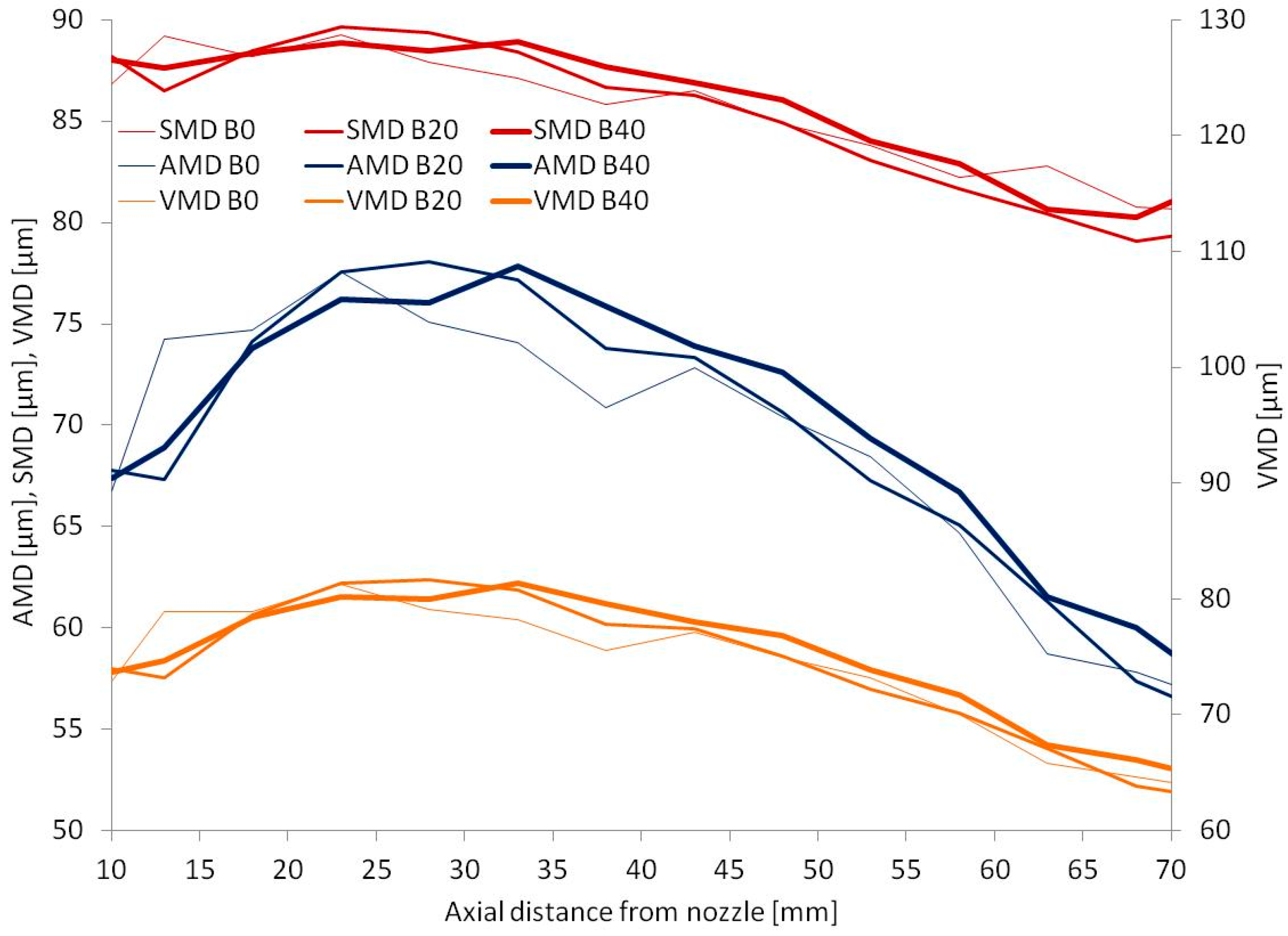
In order to compare the effect of the physical properties of biodiesel and diesel fuels on the atomization characteristics, the droplet diameter, axial mean velocity and fuel burn rate are analyzed at specific fuel injection conditions. The influence of blending ratio on droplet size distributions according to the axial distance from the nozzle tip is shown in Figure 9.
The SMD, VMD and AMD of diesel and biodiesel blending fuel decreased with an increase in the axial distance from injector tip. As can be seen in this figure, the injected jet of biodiesel blends had a smaller mean droplet diameter close to the nozzle tip. However, as we shift to higher axial distance from the nozzle tip, this trend is reversed and the SMD values of biodiesel blended fuel are higher than that of conventional diesel fuel. The VMD and AMD values have similar trends as seen in the same figure.
As it is generally known that the surface tension is a dominant factor in the droplet breakup mechanism, the higher viscosity and surface tension of the biodiesel results in the higher SMD, as well as the lower mean droplet velocities indicated in Table 7. The higher viscosity of biodiesel can become a factor in a lower axial mean velocity because it increases the friction between the nozzle surface and fuel.
3.6. Spray and Combustion Evolution
The main spray characteristics of diesel and biodiesel blends, measured in the previous section, may be employed in an estimation of the effect on the evolution of combustion.
Under the assumptions of fast chemical kinetics, spherical droplets, unity Lewis number and constant thermophysical properties, the droplet diameter is seen to decay with time according to the well-known d2-law for droplet lifetime:
with
where B is the Spalding number, λg the thermal conductivity of the gas phase and cp,g the specific heat capacity of the gas phase [21].
It can be seen that the mass burning rate is only weakly dependent (logarithmic) on the fuel properties (lower heating value, enthalpy of vaporization), and is directly related to the properties of the surrounding gas medium and to the initial droplet diameter [21]. A doubling of the initial diameter quadruples the droplet burnout time. For example, a spherical droplet of 1 mm diameter may be atomized in one million droplets of 10 μm. Based on the above assumption for the fuel burning rate being proportional to the square of its diameter, the burning rate for all one million droplets becomes 10,000 times faster.
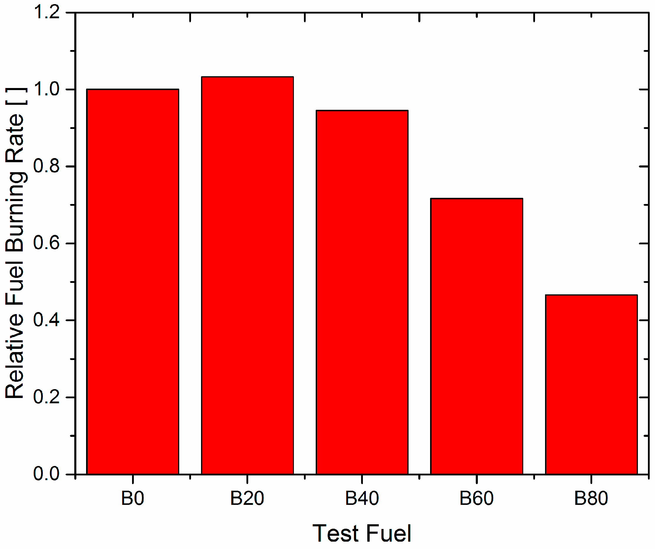
By applying this simplified calculation for the indicative fuel burning rates for each sample of 60,000 droplets measured by the LDV, we get the result of Figure 10 which compares estimated relative fuel burning rates of the sprays investigated in the above series of experiments.
According to the results of Figure 10, no significant variation in average estimated fuel burning rate is observed with B20. In fact, a slight increase is observed, which should be inside the statistical error of the measurements and the extents of applicability of the reported method for LDV size distribution measurements. On the other hand, as the biodiesel blending ratio increases, the droplet size distribution is clearly modified leading to an estimated, significant decrease in fuel burning rate. Small decreases in fuel burning rate have already been recorded in the processing of the indicator diagrams for B20 versus B0, already presented in Figure 6 and Figure 7. These results agree with what is reported in the literature [22,23,24,25].
4. Conclusions
- Combustion of B20 and B40 in the unmodified engine with pump-line-nozzle injection system resulted in modification in the evolution of combustion compared to B0. The ignition delay was reduced, while the fuel burning rate in the initial premixed combustion phase was higher.
- However, the total combustion duration for the B20 blend was higher.
- The increase of the biodiesel blending ratio appears to increase the COVimep from 8.6% (B0) to 8.8% (B20) and 9.4% (B40).
- The kinematic viscosity and surface tension become higher as the mixing ratio of the biodiesel increases, thus modifying the atomization characteristics of blended fuels.
- The surface tension of the biodiesel is higher than that of commercial diesel, which gives a lower Weber number (less strong breakup tendency).
- The SMD, VMD and arithmetic mean diameter (AMD) of diesel and biodiesel blended fuels decreased with an increase in the axial distance due to the fuel atomization process.
- Comparison of SMD values between blends show that the biodiesel blends present increasingly higher SMD than the conventional diesel fuel. The VMD and AMD values have similar trends.
- Comparison of approximate fuel burning rates for different samples of 60,000 droplets each clearly indicate a decrease in fuel burning rate for B20 and higher blends.
- The higher viscosity of biodiesel can become a factor in a lower axial mean velocity because it increases the friction (and wear) between the nozzle surface and fuel.
Acknowledgments
The authors wish to thank Yiannis Chatzinakis and Rémi Staub, for their participation in the LDV and flow visualization experiments; Fotis Bouroutzikas for his participation in the engine tests; and ELIN biofuels SA (Volos factory) for supplying the biodiesel employed in the experiments.
Author Contributions
Dimitrios N Tziourtzioumis and Anastassios M Stamatelos conceived and designed the experiments; Dimitrios N Tziourtzioumis performed the experiments; Dimitrios N Tziourtzioumis and Anastassios M Stamatelos analyzed the data; Dimitrios N Tziourtzioumis and Anastassios M Stamatelos wrote the paper.
Conflicts of Interest
The authors declare no conflict of interest.
Nomenclature
| AMD | Area mean diameter [m] |
| A/F | Air to Fuel ratio |
| B | Spalding number |
| CA | Crank angle [°] |
| COV | Coefficient of variation [·] |
| cp,g | Specific heat capacity of gas phase [kJ/kg·K] |
| DI | Direct injection |
| F | Frequency [Hz] |
| FAME | Fatty acid methyl ester |
| FBR | Fuel burning rate [s−1] |
| imep | indicated mean effective pressure [MPa] |
| ITA | Injection timing advance [°] |
| LDV | Laser Doppler Velocimetry |
| LHV | Lower heating value [MJ/kg] |
| Oh | Ohnesorge number |
| p | pressure [Pa] |
| Po | Power [kW] |
| PLN | Pump in line nozzle |
| Rej | Jet Reynolds number |
| SiC | Silicon carbide |
| SMD | Sauter mean diameter [m] |
| VMD | Volume mean diameter [m] |
| Wej | Jet Weber number |
| θ | crankangle [deg] |
| λ | wavelength [m] |
| λg | thermal conductivity of gas phase [W/mK] |
| density of liquid phase [kg/m3] |
References
- Maghbouli, A.; Yang, W.; An, H.; Li, J.; Shafee, S. Effects of injection strategies and fuel injector configuration on combustion and emission characteristics of a DI diesel engine fueled by bio-diesel. Renew. Energy 2015, 76, 687–698. [Google Scholar] [CrossRef]
- Shameer, M.P.; Ramesh, K.; Sakthivel, R.; Purnachandran, R. Effects of fuel injection parameters on emission characteristics of diesel engines operating on various biodiesel: A review. Renew. Sustain. Energy Rev. 2017, 67, 1267–1281. [Google Scholar] [CrossRef]
- Gülüm, M.; Bilgin, A. Measurements and empirical correlations in predicting biodiesel-diesel blends’ viscosity and density. Fuel 2017, 199, 567–577. [Google Scholar] [CrossRef]
- Kegl, B. Numerical analysis of injection characteristics using biodiesel fuel. Fuel 2006, 85, 2377–2387. [Google Scholar] [CrossRef]
- Wu, Z.; Zhu, Z.; Huang, Z. An experimenal study on the spray structure of oxygenated fuel using laser-based visualization and particle image velocimetry. Fuel 2006, 85, 1458–1464. [Google Scholar] [CrossRef]
- Ramadhas, A.S.; Jayaraj, S.; Muraleedharan, C. Use of vegetable as IC engine fuels: A review. Renew. Energy 2004, 29, 727–742. [Google Scholar] [CrossRef]
- Lee, C.S.; Park, S.W. An experimental and numerical study on fuel atomization characteristics of high-pressure diesel injection sprays. Fuel 2002, 81, 2417–2423. [Google Scholar] [CrossRef]
- Agarwal, A.K.; Dhar, A.; Gupta, J.G.; Kim, W.; Lee, C.S.; Park, S. Effect of fuel injection pressure and injection timing on spray characteristics and particulate size-number distribution in a biodiesel fuelled common rail direct injection diesel engine. Appl. Energy 2014, 130, 212–221. [Google Scholar] [CrossRef]
- Charalampous, G.; Hardalupas, Y. How do liquid fuel physical properties affect liquid jet development in atomisers? Phys. Fluids 2016, 28, 102106. [Google Scholar] [CrossRef]
- Reif, K. Diesel Engine Management Systems and Components; Springer Vieweg: Wiesbaden, Germany, 2014. [Google Scholar]
- TSI Software Manual; Texas Success Initiative (TSI): Austin, TX, USA, 2007.
- Automotive Fuels—Fatty Acid Methylesters (FAME) for Diesel Engines—Requirements and Test Methods. Available online: http://agrifuelsqcs-i.com/attachments/1598/en14214.pdf (accessed on 10 June 2017).
- Tat, M.E.; Van Gerpen, J.H. Measurement of Biodiesel Speed of Sound and Its Impact on Injection Timing. Available online: http://www.nrel.gov/docs/fy03osti/31462.pdf (accessed on 10 June 2017).
- Agarwal, A.K. Biofuels (alcohols and biodiesel) applications as fuels for internal combustion engines. Prog. Energy Combust. Sci. 2007, 33, 233–271. [Google Scholar] [CrossRef]
- Zhang, Y.; Boehman, A.L. Impact of biodiesel on NOx emissions in a common rail direct injection diesel engine. Energy Fuels 2007, 21, 2003–2012. [Google Scholar] [CrossRef]
- Heywood, J.B. Internal Combustion Engines Fundamentals. Available online: https://2k9meduettaxila.files.wordpress.com/2012/09/internal-combustion-engines-fundamentals-heywood.pdf (accessed on 10 June 2017).
- Help Navigator; Gamma Technologies Inc.: Westmont, IL, USA, 2009.
- Grech, N.; Mehdi, A.; Zachos, P.K.; Pachidis, V.; Singh, R. Effect of combustor geometry on performance of airblast atomizer under sub-atomizer conditions. Eng. Appl. Comput. Fluid Mech. 2012, 6, 203–213. [Google Scholar] [CrossRef]
- Tziourtzioumis, D. Experimental Investigation of the Steady State and Transient Operation of Diesel Engines Fuelled by High Percentage Biodiesel Blends; University of Thessaly: Volos, Greece, 2012. [Google Scholar]
- Lee, C.S.; Reitz, R.D. Effect of liquid properties on the breakup mechanism of high-speed liquid drops. At. Sprays 2001, 11, 1–19. [Google Scholar]
- Available online: http://www.borgwarner.com/ (accessed on 10 July 2017).
- Kousoulidou, M.; Fontaras, G.; Ntziachristos, L.; Samaras, Z. Biodiesel blend effects on common-rail diesel combustion and emissions. Fuel 2010, 89, 3442–3449. [Google Scholar] [CrossRef]
- Fang, T.; Lee, C.F. Bio-diesel effects on combustion processes in an HSDI diesel engine using advanced injection strategies. Proc. Combust. Inst. 2009, 32, 2785–2792. [Google Scholar] [CrossRef]
- Hamasaki, K.; Kinoshita, E.; Tajima, H.; Takasaki, K.; Morita, D. Combustion characteristics of diesel engines with waste vegetable oil methyl ester. In Proceedings of the 5th International Symposium on Diagnostics and Modeling of Combustion in Internal Combustion Engines, Nagoya, Japan, 1–4 July 2001. [Google Scholar]
- Yehliu, K.; Boehman, A.L.; Armas, O. Emissions from different alternative diesel fuels operating with single and split fuel injection. Fuel 2010, 89, 423–437. [Google Scholar] [CrossRef]
Figure 1.
Low injection pressure (10 bar) experimental setup, including water tunnel, fuel tank, fuel pump, injection nozzle and TSI probe.
Figure 1.
Low injection pressure (10 bar) experimental setup, including water tunnel, fuel tank, fuel pump, injection nozzle and TSI probe.

Figure 2.
Experimental setup schematic diagram: LDV 1D components, injector nozzle and computer equipped with FlowSizer software.
Figure 2.
Experimental setup schematic diagram: LDV 1D components, injector nozzle and computer equipped with FlowSizer software.
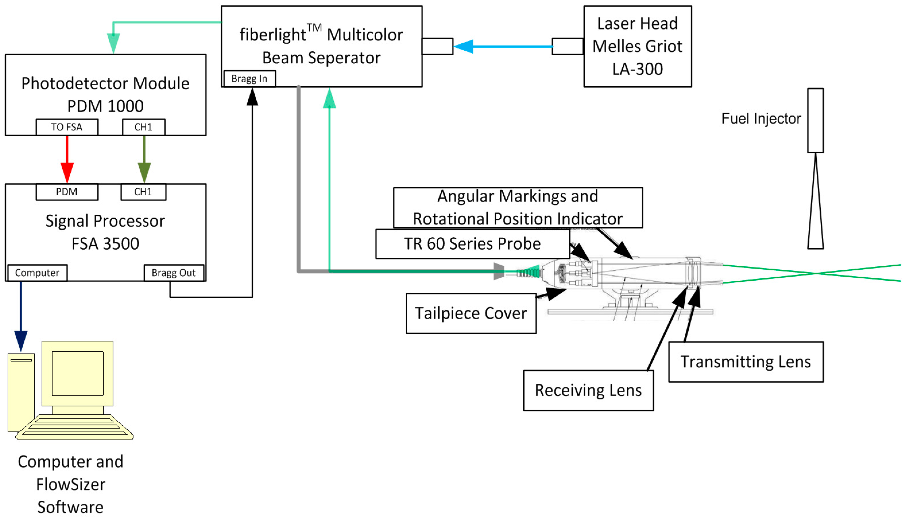
Figure 3.
Schematic representation of the flow visualization layout.

Figure 4.
Percentage coefficient of variation of imep for B0, B20 and B40 during two steady state operation points, 2600 rpm/12.7 Nm and 3250 rpm/16.2 Nm.
Figure 4.
Percentage coefficient of variation of imep for B0, B20 and B40 during two steady state operation points, 2600 rpm/12.7 Nm and 3250 rpm/16.2 Nm.

Figure 5.
Comparison of combustion characteristics (burn duration and crank angle of 50% burn point) for B0 and B20 during the steady state operation point, 3250 rpm/16.2 Nm.
Figure 5.
Comparison of combustion characteristics (burn duration and crank angle of 50% burn point) for B0 and B20 during the steady state operation point, 3250 rpm/16.2 Nm.
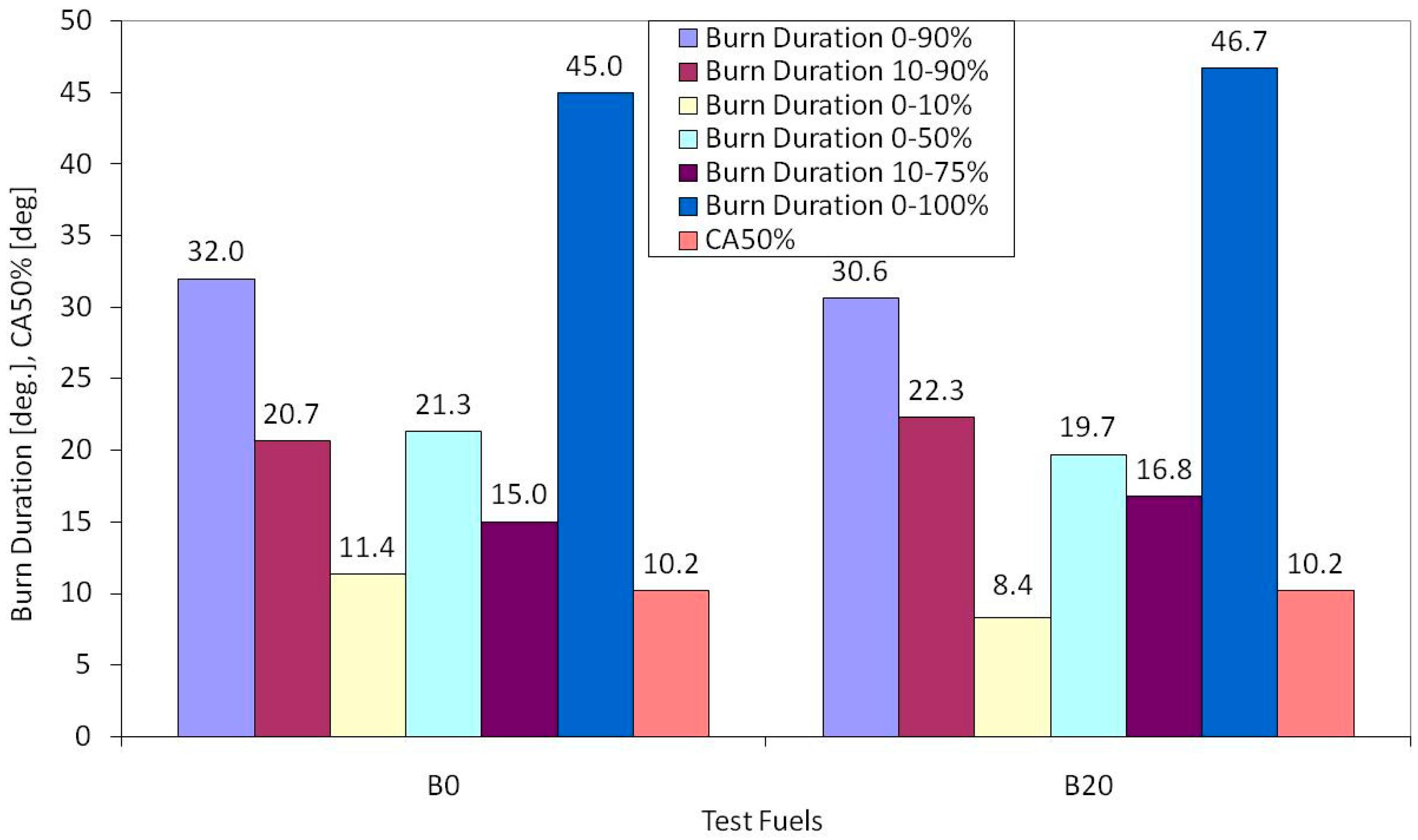
Figure 6.
Comparison of mass fraction burned versus crank angle curve for B0 and B20 blend during the operation point, 2600 rpm/12.7 Nm.
Figure 6.
Comparison of mass fraction burned versus crank angle curve for B0 and B20 blend during the operation point, 2600 rpm/12.7 Nm.
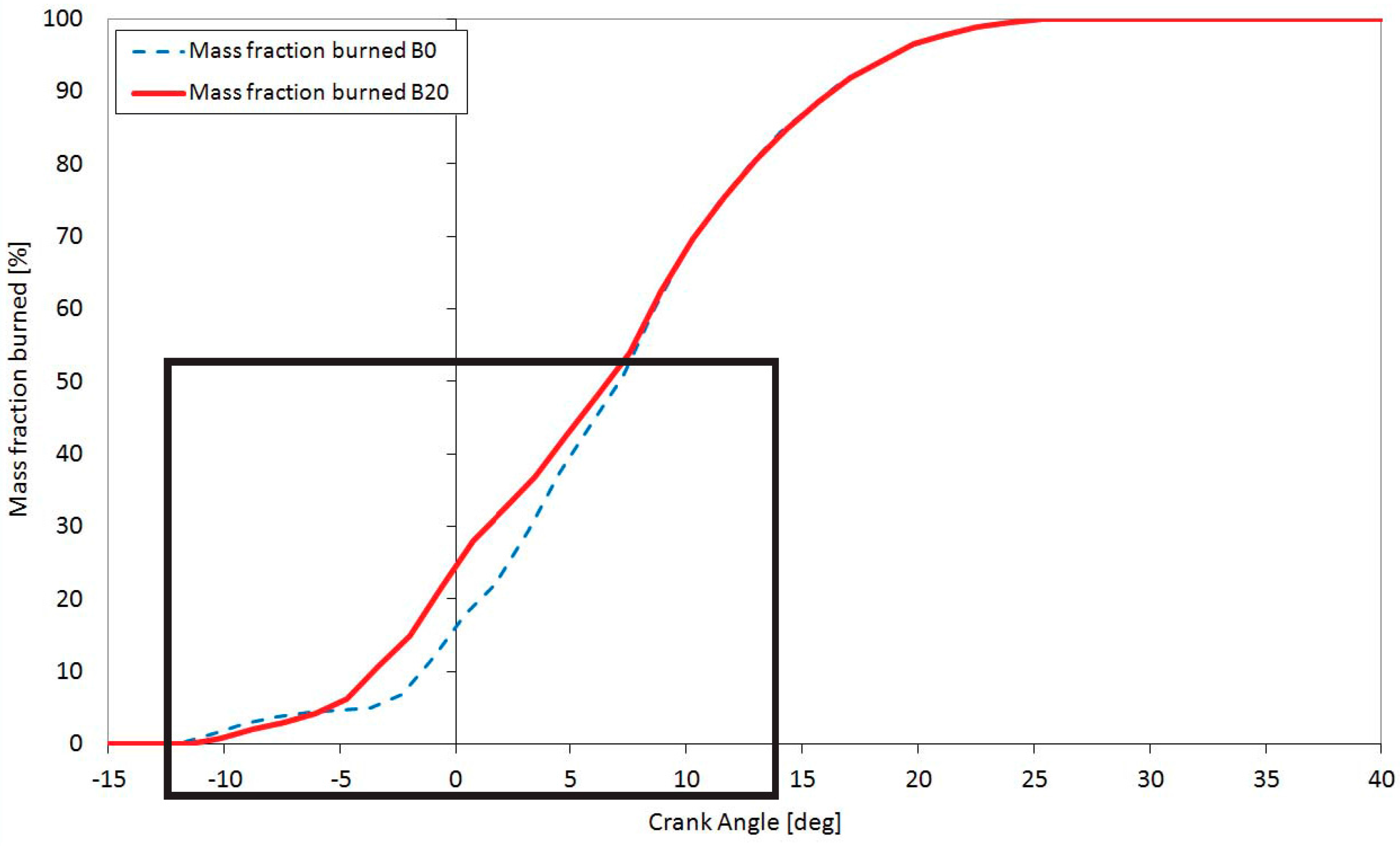
Figure 7.
Comparison of mass fraction burned versus crank angle curve for B0 and B20 blend during the filter loading operation point 3250 rpm/16.2 Nm.
Figure 7.
Comparison of mass fraction burned versus crank angle curve for B0 and B20 blend during the filter loading operation point 3250 rpm/16.2 Nm.

Figure 8.
Comparison of spray evolution using low pressure nozzle for B0, B40 and B100 fuels (3 cm from the tip of the nozzle) under specific injection conditions: Pinj = 10 bar, and Pamb = 1.01 bar.
Figure 8.
Comparison of spray evolution using low pressure nozzle for B0, B40 and B100 fuels (3 cm from the tip of the nozzle) under specific injection conditions: Pinj = 10 bar, and Pamb = 1.01 bar.

Figure 9.
SMD, AMD, and VMD distributions at several axial distances from nozzle tip (low pressure injection) for B0, B20 and B40 fuels.
Figure 9.
SMD, AMD, and VMD distributions at several axial distances from nozzle tip (low pressure injection) for B0, B20 and B40 fuels.

Figure 10.
Estimated relative fuel burning rates for 60,000 droplets’ samples of B0, B20, B40, B60 and B80 fuels respectively (B0 = 1).
Figure 10.
Estimated relative fuel burning rates for 60,000 droplets’ samples of B0, B20, B40, B60 and B80 fuels respectively (B0 = 1).


Table 1.
Test matrix.
| Experimental Setup | RF91 DI Diesel Engine | LDV (Low Injection Pressure Setup) | ||||
|---|---|---|---|---|---|---|
| Fuel | Injection Timing Advance | Cycle-to-Cycle Variation | Indicator Diagram Analysis | Injection Characteristics | Fuel Atomization Characteristics | Spay Evolution |
| B0 | ||||||
| B20 | ||||||
| B40 | ||||||
| B60 | ||||||
| B80 | ||||||
| B100 | ||||||
Table 2.
Ruggerini RF91 engine specifications.
| Engine Type | DI 4 Stroke Naturally Aspirated Diesel Engine |
|---|---|
| Engine model | RF91 |
| Number of cylinders | 1 |
| Bore | 90 mm |
| Stroke | 75 mm |
| Rated power | 8.1 kW, 3600 rpm |
| Rated torque | 25 Nm, 2500 rpm |
| Compression ratio | 18.5:1 |
| Diesel particulate filter | IBIDEN SiC filter |
Table 3.
RF91 conventional fuel injection system specifications.
| Injection System Type | New Diesel Pump-in-Line Nozzle Injection System |
|---|---|
| Needle diameter | 4 mm |
| Number and diameter of nozzle holes | 4 × 0.24 mm |
| Nozzle hole length | 0.6 mm |
| Pin height | 0.125–0.175 mm |
| Sump volume | 0.36 mm3 |
| Opening pressure | 210 bar |
| Pump plunger diameter | 7 mm |
| Drive rod length | 65.8–66 mm |
| High pressure line length | 400 mm |
Table 4.
Fuel properties.
| Specifications/Ranges | B0 | B20 | B40 | B60 | B80 | B100 |
|---|---|---|---|---|---|---|
| Density (15 °C) (kg/m3) | 825 | 840 | 852 | 864 | 876 | 885 |
| Viscosity (40 °C) (cSt) | 2.493 | 3.039 | 3.384 | 3.730 | 4.075 | 4.720 |
| Surface tension (N/m) | 0.02600 | 0.02637 | 0.02674 | 0.02711 | 0.02748 | 0.02800 |
| Cetane number | 50 | - | - | - | - | 55 |
| Stoichiometric A/F ratio | 14.5 | 14.10 | 13.69 | - | - | 12.48 |
| Lower heating value [MJ/kg] | 43.3 | 42.18 | 41.06 | - | - | 37.7 |
Table 5.
Calculated crankshaft rotations until NOP (impact of bulk modulus).
| Variable | Value |
|---|---|
| Crankshaft rotation required to reach the NOP-B0 [CA] | 10.22 |
| Crankshaft rotation required to reach the NOP-B20 [CA] | 10.0 |
| Crankshaft rotation required to reach the NOP-B40 [CA] | 9.8 |
| Crankshaft rotation required to reach the NOP-B100 [CA] | 9.12 |
Table 6.
Calculated injection timing advances (impact of speed of sound).
| Engine Speed [rpm] | Time [ms]/CA | Total CA for B0 Case-PtN Time | Total CA for B20 Case-PtN Time | Total CA for B40 Case-PtN Time | Total CA for B100 Case-PtN Time |
|---|---|---|---|---|---|
| 1600 | 0.1042 | 2.95 | 2.93 | 2.91 | 2.86 |
| 1700 | 0.0980 | 3.13 | 3.11 | 3.09 | 3.03 |
| 1800 | 0.0926 | 3.32 | 3.30 | 3.28 | 3.21 |
| 1900 | 0.0877 | 3.50 | 3.48 | 3.46 | 3.39 |
| 2000 | 0.0833 | 3.69 | 3.66 | 3.64 | 3.57 |
| 2100 | 0.0794 | 3.87 | 3.85 | 3.82 | 3.75 |
| 2200 | 0.0758 | 4.06 | 4.03 | 4.00 | 3.93 |
| 2300 | 0.0725 | 4.24 | 4.21 | 4.19 | 4.10 |
| 2400 | 0.0694 | 4.42 | 4.40 | 4.37 | 4.28 |
| 2500 | 0.0667 | 4.61 | 4.58 | 4.55 | 4.46 |
| 2600 | 0.0641 | 4.79 | 4.76 | 4.73 | 4.64 |
| 2700 | 0.0617 | 4.98 | 4.95 | 4.91 | 4.82 |
| 2800 | 0.0595 | 5.16 | 5.13 | 5.10 | 5.00 |
| 2900 | 0.0575 | 5.35 | 5.31 | 5.28 | 5.17 |
| 3000 | 0.0556 | 5.53 | 5.49 | 5.46 | 5.35 |
| 3100 | 0.0538 | 5.71 | 5.68 | 5.64 | 5.53 |
| 3200 | 0.0521 | 5.90 | 5.86 | 5.82 | 5.71 |
| 3250 | 0.0513 | 5.99 | 5.95 | 5.91 | 5.80 |
| 3300 | 0.0505 | 6.08 | 6.04 | 6.01 | 5.89 |
| 3400 | 0.0490 | 6.27 | 6.23 | 6.19 | 6.07 |
| 3500 | 0.0476 | 6.45 | 6.41 | 6.37 | 6.25 |
| 3600 | 0.0463 | 6.64 | 6.59 | 6.55 | 6.42 |
Table 7.
Mean droplet velocity, Jet We, Jet Re and Jet Oh number for all blends
| Test Fuel | B0 | B20 | B40 | B60 | B80 | B100 |
|---|---|---|---|---|---|---|
| Mean droplet velocity [m/s] | 25.31 | 24.95 | 24.60 | 24.25 | 23.92 | 23.81 |
| Wej (Jet Weber number) | 5.91 | 5.66 | 5.43 | 5.21 | 4.50 | 4.86 |
| Rej (Jet Reynolds number) | 1879 | 1642 | 1453 | 1300 | 1174 | 1078 |
| Oh (Ohnesorge number) | 0.034 | 0.038 | 0.043 | 0.047 | 0.051 | 0.055 |
© 2017 by the authors. Licensee MDPI, Basel, Switzerland. This article is an open access article distributed under the terms and conditions of the Creative Commons Attribution (CC BY) license (http://creativecommons.org/licenses/by/4.0/).
Share and Cite
MDPI and ACS Style
Tziourtzioumis, D.N.; Stamatelos, A.M. Experimental Investigation of the Effect of Biodiesel Blends on a DI Diesel Engine’s Injection and Combustion. Energies 2017, 10, 970. https://doi.org/10.3390/en10070970
AMA Style
Tziourtzioumis DN, Stamatelos AM. Experimental Investigation of the Effect of Biodiesel Blends on a DI Diesel Engine’s Injection and Combustion. Energies. 2017; 10(7):970. https://doi.org/10.3390/en10070970
Chicago/Turabian StyleTziourtzioumis, Dimitrios N, and Anastassios M Stamatelos. 2017. "Experimental Investigation of the Effect of Biodiesel Blends on a DI Diesel Engine’s Injection and Combustion" Energies 10, no. 7: 970. https://doi.org/10.3390/en10070970
Note that from the first issue of 2016, this journal uses article numbers instead of page numbers. See further details here.