Article

Complementary Power Control for Doubly Fed Induction Generator-Based Tidal Stream Turbine Generation Plants

1
Laboratory of Research in Automatic Control—LA.R.A, National Engineering School of Tunis (ENIT), University of Tunis El Manar (UTM), BP 37, Le Belvédère, 1002 Tunis, Tunisia
2
Automatic Control Group—ACG, Department of Automatic Control and Systems Engineering, Engineering School of Bilbao, University of the Basque Country (UPV/EHU), 48012 Bilbao, Spain
*
Author to whom correspondence should be addressed.
Energies 2017, 10(7), 862; https://doi.org/10.3390/en10070862
Submission received: 19 April 2017 / Revised: 1 June 2017 / Accepted: 23 June 2017 / Published: 28 June 2017
(This article belongs to the Special Issue Sustainable and Renewable Energy Systems)

Abstract

:
The latest forecasts on the upcoming effects of climate change are leading to a change in the worldwide power production model, with governments promoting clean and renewable energies, as is the case of tidal energy. Nevertheless, it is still necessary to improve the efficiency and lower the costs of the involved processes in order to achieve a Levelized Cost of Energy (LCoE) that allows these devices to be commercially competitive. In this context, this paper presents a novel complementary control strategy aimed to maximize the output power of a Tidal Stream Turbine (TST) composed of a hydrodynamic turbine, a Doubly-Fed Induction Generator (DFIG) and a back-to-back power converter. In particular, a global control scheme that supervises the switching between the two operation modes is developed and implemented. When the tidal speed is low enough, the plant operates in variable speed mode, where the system is regulated so that the turbo-generator module works in maximum power extraction mode for each given tidal velocity. For this purpose, the proposed back-to-back converter makes use of the field-oriented control in both the rotor side and grid side converters, so that a maximum power point tracking-based rotational speed control is applied in the Rotor Side Converter (RSC) to obtain the maximum power output. Analogously, when the system operates in power limitation mode, a pitch angle control is used to limit the power captured in the case of high tidal speeds. Both control schemes are then coordinated within a novel complementary control strategy. The results show an excellent performance of the system, affording maximum power extraction regardless of the tidal stream input.

1. Introduction

The growth of and need for renewable energy systems have led the European Commission to set a cost of energy reduction target of 0 . 20 euro/kWh by 2020 for wave and tidal energy [1]. However, analyzing current demonstration projects suggests that the Levelized Cost of Energy (LCoE) will not meet this target. The European Ocean Energy Forum has suggested, in its Draft Roadmap [2], that the cost of energy from wave and tidal farms could tend towards 0 . 10 euro/kWh by 2030 under the right conditions and through device deployment [3]. In this sense, renewable tidal energy systems are meant to produce electricity and ensure the cost reduction. To do so, these systems use power electronic converters in order to control and handle the flow of electrical power transferred to the grid. The use of the power converters is important since they represent the interface of the distributed power systems [4]. These power converters are optimally designed to assure maximum power production, provide reliable operation and ensure the protection of the power plant system [5]. Furthermore, the use of the Doubly-Fed Induction Generator (DFIG) associated with the power converters in a back-to-back configuration has been exploited for high power applications [6,7]. In this context, power electronics are changing the basic characteristics of the Tidal Stream Turbine (TST) from being an energy source to being an active power source for the grid. These devices enable efficient conversion of the variable frequency output of the generator, which is driven by a variable speed tidal turbine, to a fixed frequency appropriate for the grid [8]. The attractiveness of the tidal power stems from the huge energy potential and its predictable characteristics. The horizontal-axis turbines represent the most common type of tidal device, since horizontal-axis turbine devices account for 76 % of research and development efforts in tidal devices over the world, as explained in [9]. The largest tidal power station in the world is Sihwa Lake situated in South Korea, which generates a peak rating of 254 MW, after La Rance Tidal Power Station in France with a total power output of 240 MW [10].
Tidal stream turbines are designed to extract the kinetic energy contained in the marine currents. These systems are intended to be installed in high energetic sites and are subjected to turbulence and strong waves where the force of the tidal current is large and the flow is highly variable [11,12]. Therefore, turbine design requires a precise knowledge of such high velocity flow in order to optimize the generated power output. This means that they need to be regulated, with a way of limiting the output power and shedding mechanical load at high flow speeds. In this context, the control of the generated power in a variable speed operation is ensured by the use of power electronic converters, while the blade pitch angle control is devoted to the limitation of the power in the case of the high tidal flow [13].
In the literature, the power control maximization is achieved by means of the DFIG through the back-to-back converter [14,15]. The Rotor Side Converter (RSC) control is used to keep the rotational speed of the generator at its optimal value and to minimize the core losses, while the Grid Side Converter (GSC) control aims to maintain the voltage of the DC-link and control the reactive power [16,17]. A variable speed control strategy of a Marine Current Turbine (MCT) with a fixed pitch angle was proposed in [18]. The results show that the proposed control strategy is effective in terms of speed tracking, and it has been analyzed with respect to the swell effect for the tidal input model. However, the active power exhibits some tracking errors. In power limitation mode, the control is ensured by the angular position of the blades according to the hydrodynamic power limitation targets. Two control strategies are investigated in [19]; the stall and pitch angle controls. A comparative study about stall and pitch control of a TST was discussed. The study suggests that the stall-regulated systems are not able to keep a constant power output in the case of strong tidal velocity. The pitch regulation control contributes to more efficient results regarding the energy yields. Several research works focused on the pitch angle control as discussed in [20,21]. To overcome the drawbacks of a fixed pitch angle control, a novel complementary control is presented in this paper. This control combines both aforementioned strategies to provide a suitable switching tool for efficient and robust energy tidal conversion against different tidal velocities. This is achieved by the proposed switching algorithm, ensuring a smooth transition between variable speed mode and power limitation mode.
In this paper, the modeling and control of a TST-based DFIG and AC-DC-AC Pulse Width Modulation (PWM) power converter are presented. The novel control strategy has a valuable role in order to improve all aspects of the tidal stream generator and a strong influence on the dynamic behavior of the system. This study provides evidence that operating the turbine in variable speed mode will increase the energy yield of the turbine by allowing it to work at its maximum power coefficient over a wide range of tidal speeds. In the case of strong tidal currents, the pitch regulation is conceived to afford the excess power and keep the turbine operating within the specified limits. The goals, when controlling a variable-speed TST , are optimizing the harnessed energy, regulating the generated power and reducing mechanical loads. Therefore, it is obvious that there is a need to improve the efficiency of the studied system and the produced power potential. Below rated flow speed, the turbine is adjusted to keep the tip speed ratio at its optimal value. To do so, a voltage oriented strategy is used to regulate the GSC, and a stator flux control is applied in the RSC including the rotational speed and the rotor currents control loops. A rotational speed control based on a proportional integral controller is used to track the optimal regime characteristic by implementing a Maximum Power Point Tracking (MPPT) approach. At high tidal speed, the mechanical control of the blade pitch angle is set using a proportional controller to control the pitch actuator in order to limit the active power. A switch controller is implemented based on a novel algorithm developed to ensure a smooth transition between both operation modes.
The remainder of this paper is organized as follows. Section 2 introduces the theory behind tidal power. The hydrodynamic turbine model, the DFIG and the back-to-back converter are presented in Section 3. Section 4 discusses the control statement detailing two control strategies that are proposed for the rotational speed and pitch angle controls. Then, it deals with the novel complementary control, which combines both control schemes. Three demonstrative study cases are presented and discussed in Section 5. Finally, concluding remarks are drawn in Section 6.

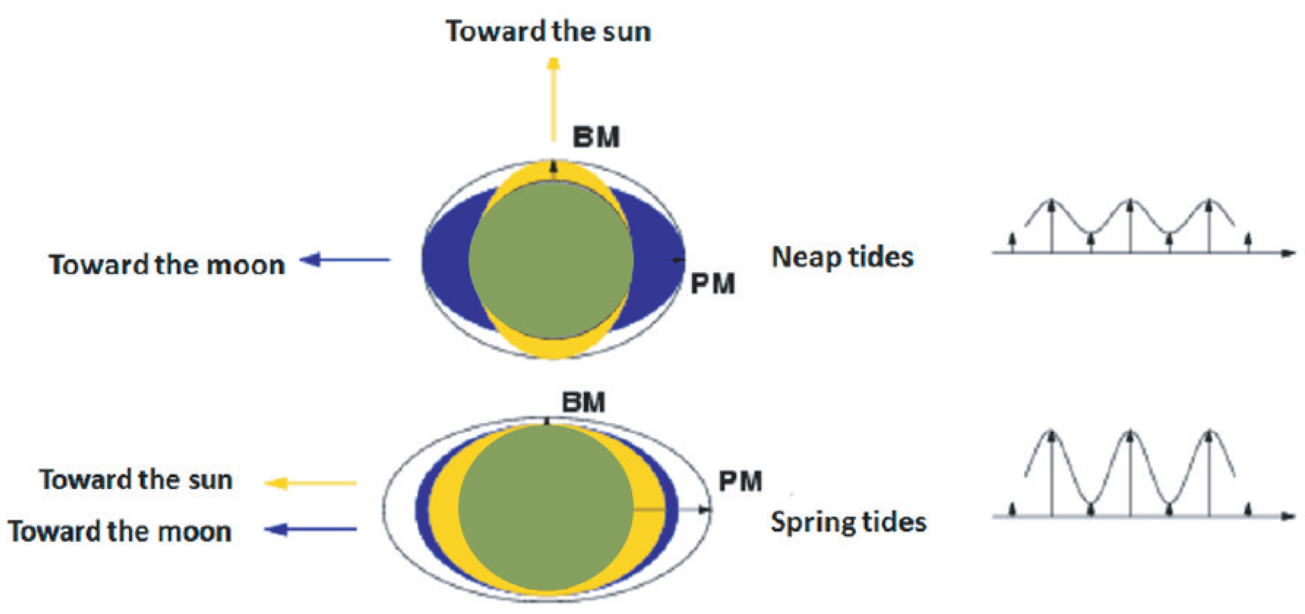
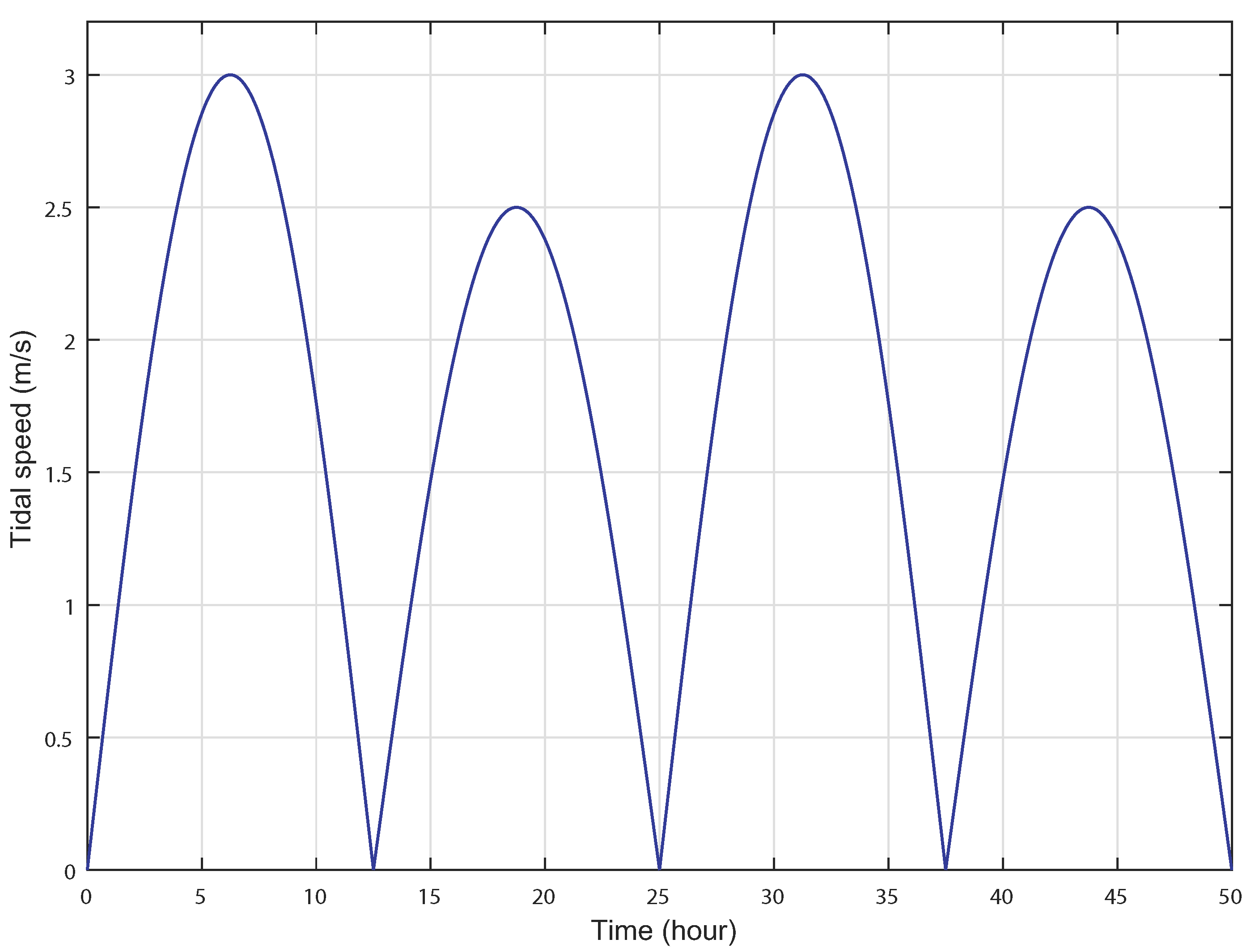
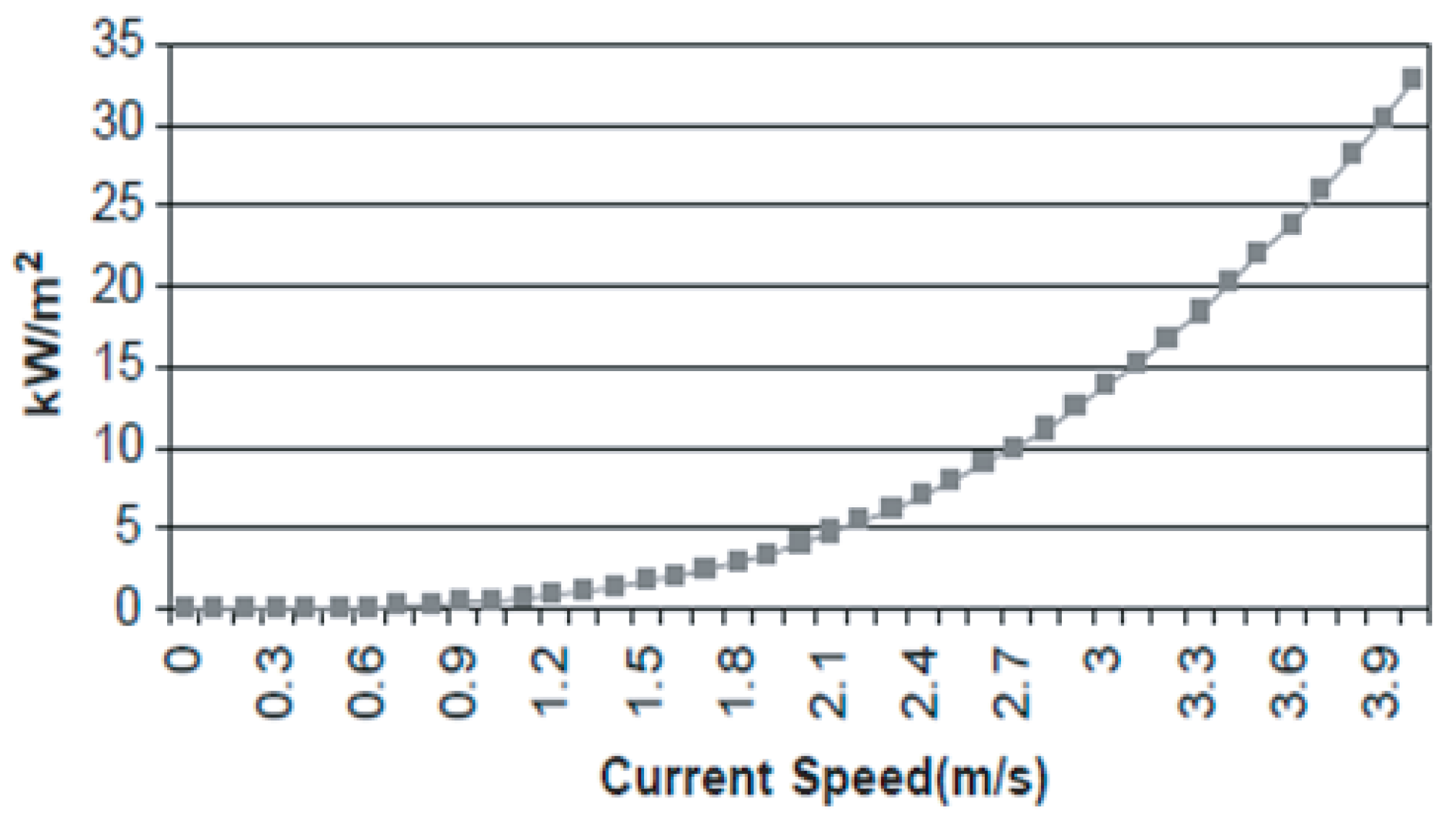
2. Background on Tidal Power

Tidal currents are generated from the ebb and flow of the tides. Besides, these currents are affected by the climate influences and the weather disturbances [22]. Under the effect of gravitational attraction, the Earth is both attracted and repulsed by the Moon. As illustrated in Figure 1, when the Sun and the Moon are orthogonal to the Earth, their impacts oppose each other: these are the neap tides. Whereas, when the axes are aligned, the Sun amplifies the impact of the Moon, generating the spring tides [23].
Tidal currents are predictable in time and in amount of current velocity. This feature is extremely essential for a successful integration of the turbines with the grid [24]. For this kind of energy, the technology of the tidal turbine is very mature and has helped to advance its technological readiness level [25]. TST systems are installed in locations with high tidal current speed or strong continuous ocean currents. Lying down at the bottom of the seabed, they extract power from the running water. Tidal velocity may be measured using an Acoustic Doppler Current Profiler (ADCP) at a specific time period and water depth [26].
There are many areas of the world where extreme tidal currents may be observed, but the waveform of tidal velocity varies at different locations of the Earth. Among myriad tidal speed profiles, Figure 2 shows a semidiurnal tide with monthly variations, which is found in Raz de Sein Brittany, France. This type of tide, which consists of spring and neap tides, has a period of, approximately, 12 h and 25 min [27].
The flux of kinetic energy in a tidal current is related to the speed of water passing through the cross-section of this channel. It is expressed in (W/m2) as given by [28] as:
P = 1 2 ρ A V 3 d A A
where ρ is the fluid density (kg/m3), A is the cross-sectional area of the turbine rotor (m2) and V is the component of the current flow velocity perpendicular to the cross-section of the channel (m/s) [28].
Equation (1) can be modified to allow the definition of a convenient average velocity V A , across the cross-section of the channel. The simplification is expressed as:
A V A 3 = A ( V 3 d A )
The provided flux density variation with V A is depicted in Figure 3, which shows the influence of the flow speed on kinetic energy [29].

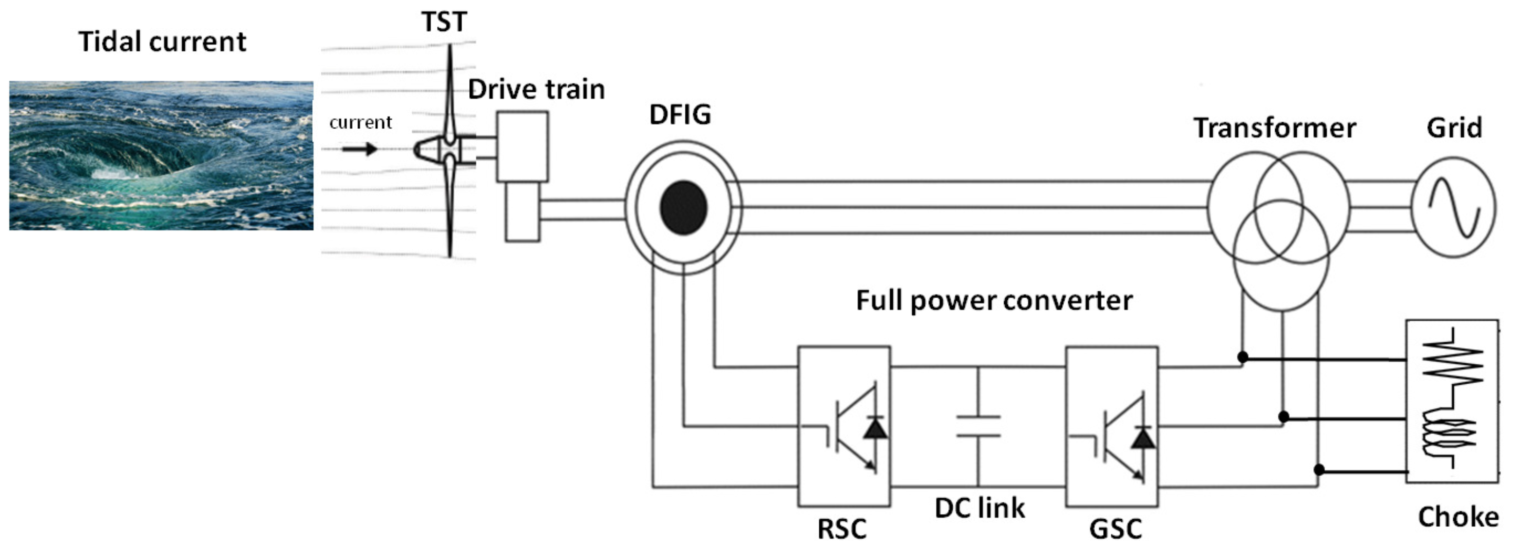
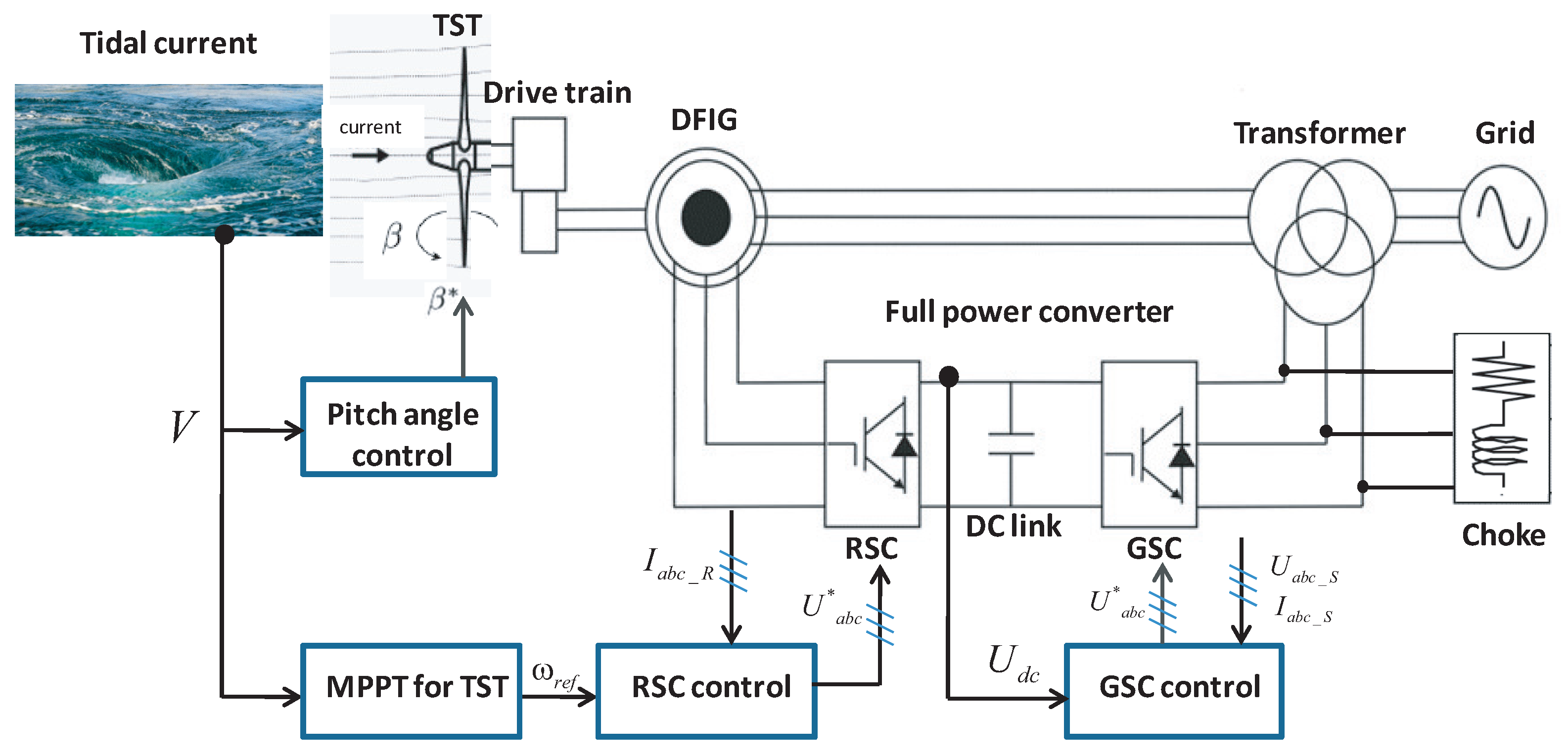
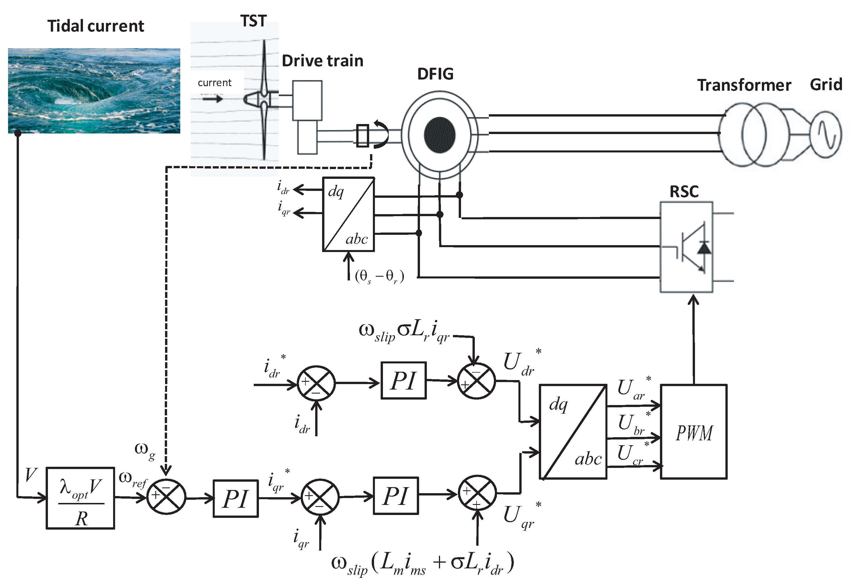
3. System Description

The configuration of a DFIG-based TST system is shown in Figure 4. The DFIG is essentially a wound rotor induction generator in which the rotor circuit can be controlled by external devices to achieve variable speed operation. The stator of the generator is connected to the grid through a transformer, whereas the rotor connection to the grid is done through AC-DC-AC power converters.

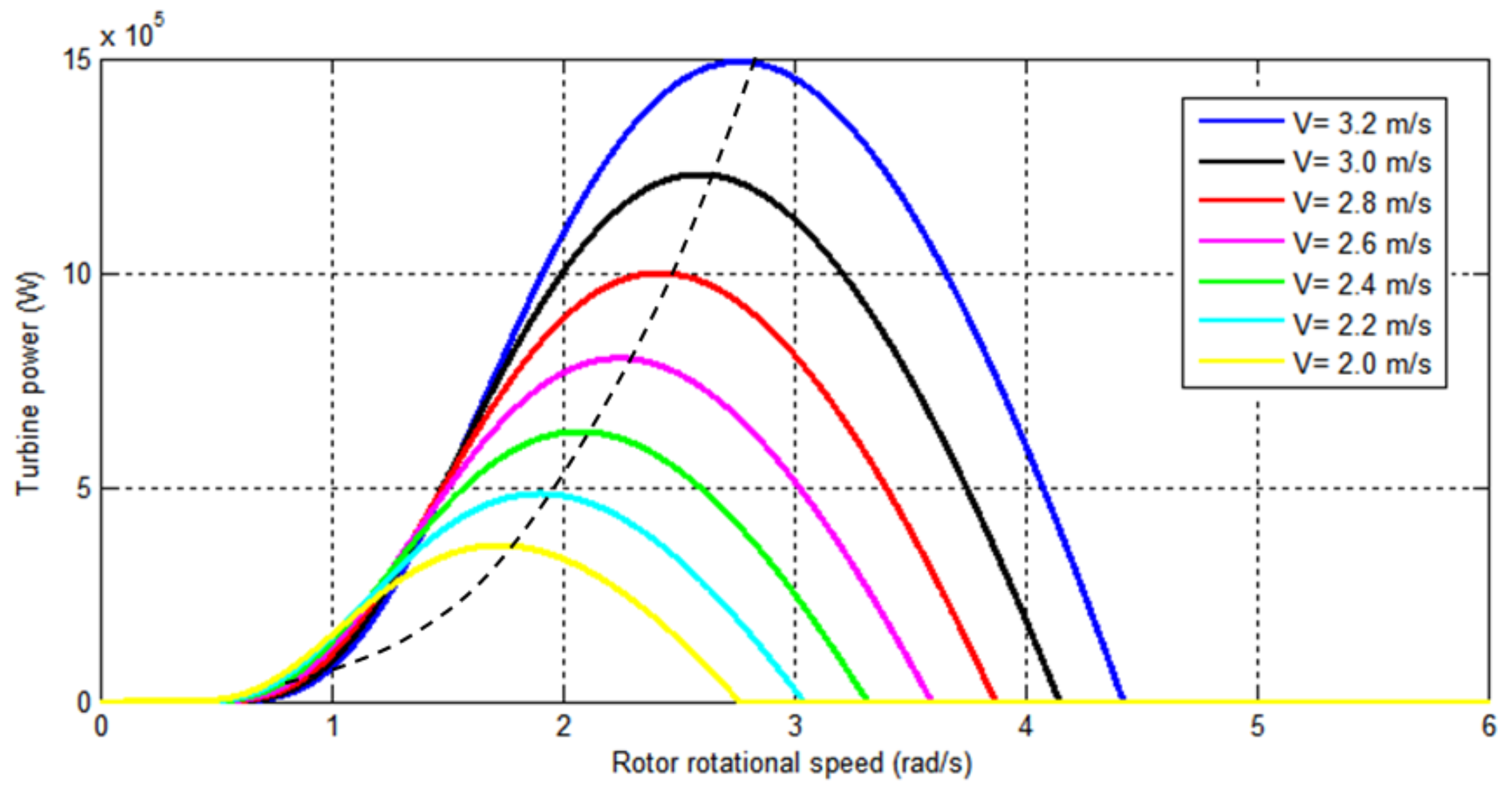
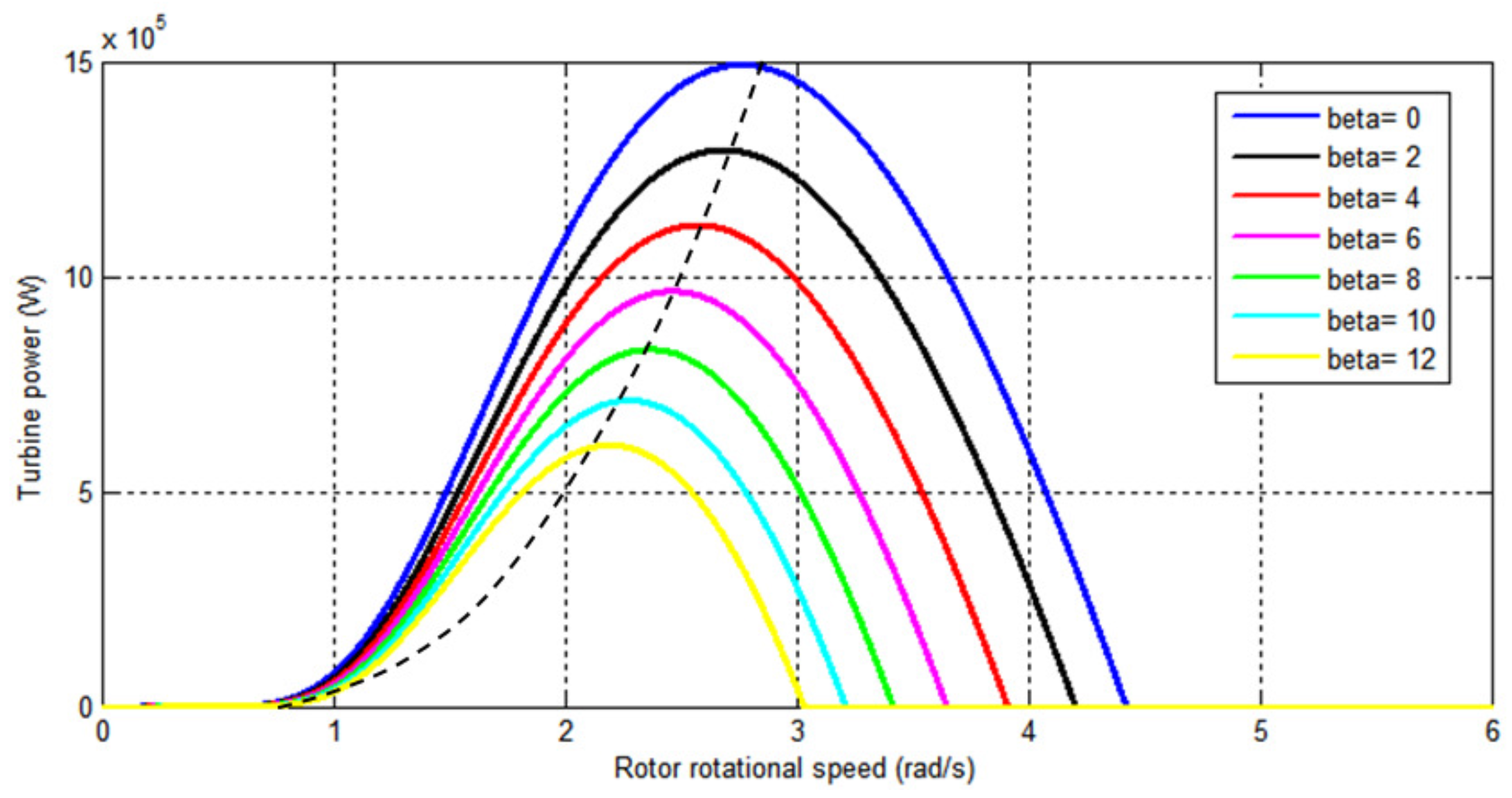
3.1. Hydrodynamic Turbine Model

The amount of power captured from a tidal turbine is governed as follows [30]:
P t = 1 2 C p ( λ , β ) ρ π R 2 V 3
where P t is the turbine power (W), R is the radius of the turbine blades (m) and C p is the power coefficient. The expression of C p is obtained by an approximating function, which depends on the blades pitch angle β (°) and the tip-speed ratio, λ , defined as follows [31]:
λ = ω t R V
where ω t is the rotational speed of the rotor (rad/s).
The hydrodynamic torque, expressed in (Nm) and developed by the tidal turbine, is given as follows:
T t s t = P t ω t

3.2. Drive-Train Two-Mass Model

The hydrodynamic torque, generated by the rotation of the rotor, is transferred to the generator via the drive train [32]. In order to model the drive-train, a two-mass model is used whereby the rotor and the generator are connected together via a flexible shaft, which has stiffness K s h (Nm/rad) and damping D s h (Nms/rad) coefficients. The dynamics of the drive-train two-mass is expressed as follows:
T t s t - T t = 2 H t d ω t d t
T t = D s h ( ω t - ω g ) + K s h ( ω t - ω g ) d t
T t - T e m = 2 H g d ω g d t
where T t is the mechanical torque from the generator shaft (Nm), T e m is the generator electromagnetic torque (Nm) and ω g is the generator rotational speed (rad/s). H t and H g are the inertia constants expressed in (s) for the turbine and generator, respectively.

3.3. Doubly-Fed Induction Generator Model

The DFIG-based TST will offer many advantages, such as the ability to generate power at variable speed based on four quadrants’ active and reactive power capabilities [33,34]. Furthermore, the DFIG is robust and requires little maintenance [35]. For the proposed control strategy, the generator’s dynamic model is defined in the synchronous d-q frame using Park’s transformation as detailed in [36]. The expressions of the stator and rotor d-q axis voltages in (V) are given as follows:
U s d = R s I s d + d φ s d d t - ω s φ s q U s q = R s I s q + d φ s q d t - ω s φ s d U r d = R r I r d + d φ r d d t - ω r φ r q U r q = R r I r q + d φ r q d t - ω r φ r d
The direct and quadrature components of the stator and rotor flux in (Wb) are defined as:
φ s d = L s I s d + L m I r d φ s q = L s I s q + L m I r q φ r d = L r I r d + L m I s d φ r q = L r I r q + L m I s q
The DFIG electromagnetic torque is expressed in the d-q frame as:
T e m = 3 2 p L m I s q I r d - I s d I r q
where I s d q , I r d q are the stator and rotor d-q axis currents (A) , ω s , ω r are the stator and rotor pulsations (rad/s), R s and R r are the stator and rotor resistances ( Ω ) , L s and L r are the stator and rotor inductances (H) , respectively, L m represents the magnetizing inductance (H) and p is the pole pair number.

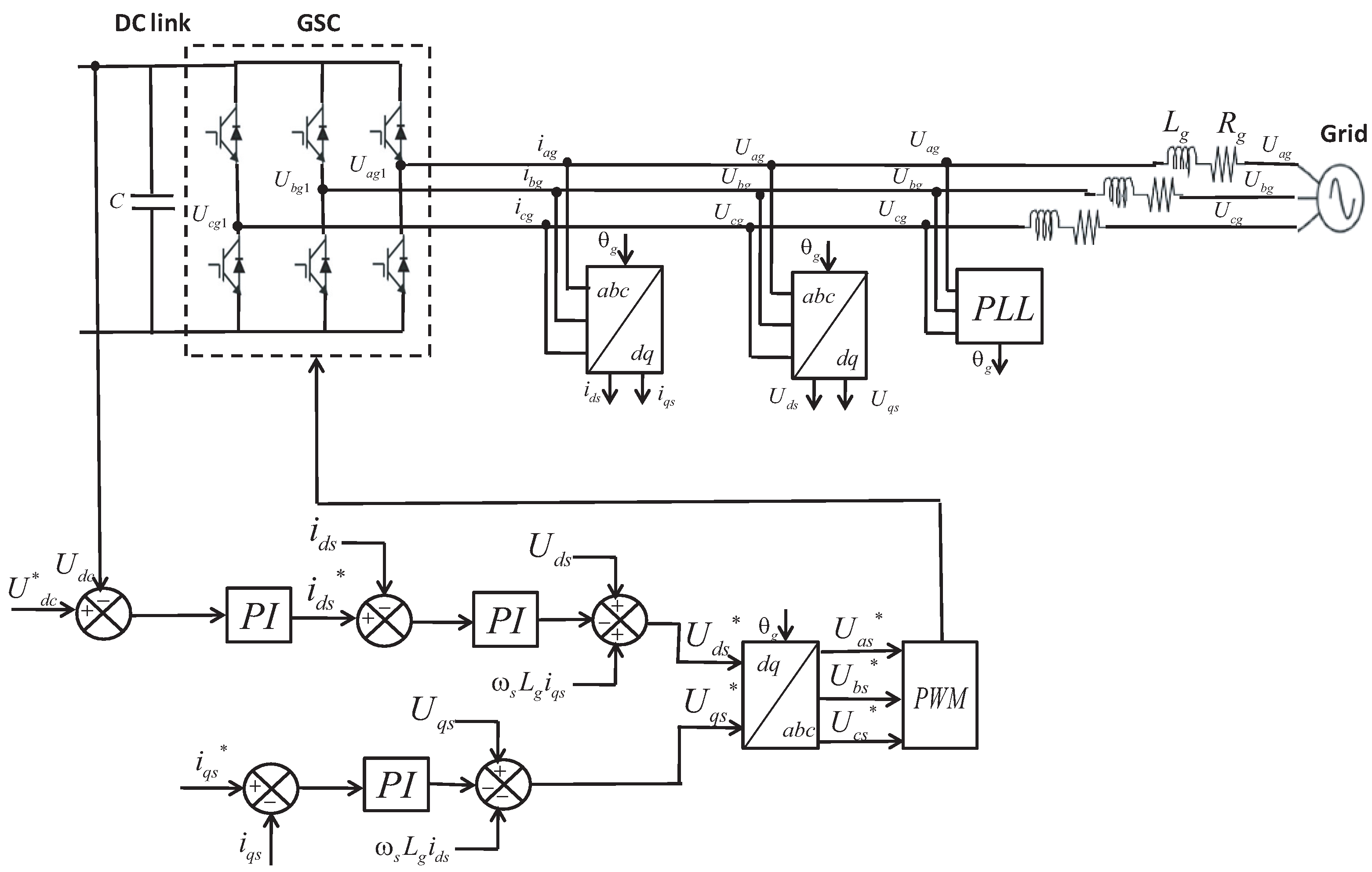
3.4. Back-To-Back Converters

The use of two six switch-based converters connected in a back-to-back configuration with an intermediate DC-link capacitor has the advantage of allowing for vector control on both the generator and grid-side converters [36]. The used full AC-DC-AC power converter consists of an RSC and a GSC. The RSC is intended to control the operation of the generator. According to the dynamical model of the DFIG, which is defined in the d-q frame, the vector control strategy is used. The objective of the GSC is to keep the DC-link voltage constant regardless of the magnitude and direction of the rotor power. A vector control strategy is employed to control the reactive power [37].
The exchanged active and reactive power in (W) and (VAR), respectively, of the system can be calculated by:
P g = 3 2 U d g I d g - U q g I q g
Q g = 3 2 U q g I d g - U d g I q g
where U d g , U q g (V) and I d g , I q g (A) are the grid voltages and currents in the d and q reference frame, respectively.
The d-axis of the synchronous frame and the grid voltage vector are aligned ( U d g = U g ) and ( U q g = 0 ) in order to achieve the voltage oriented control. Therefore, the expressions of the active and reactive power are as follows:
P g = 3 2 U g I d g
Q g = - 3 2 U g I q g
The relationship between the power stored in the DC-link and the power flowing to the grid can be given as:
P g = 3 2 U g I d g = U d c i d c
where U d c (V) and i d c (A) are the voltage and current across the DC-link, respectively.

4. Control Objectives and Strategies

The proposed complementary control strategy describes how the TST plant is handled to maximize the obtained power output. This is achieved by adequately adjusting the rotational speed of the rotor at a steady-state for each tidal speed input within the range of the turbine operation. In the operation of a variable speed, depending on the value of the nominal tidal speed, two regions are distinguished. On the one hand, when the plant is operating below nominal power, the main control objectives are maximizing the power captured from the tides and minimizing the loads submitted by the drive-train shaft; whereas, when operating in the full load regime, it is necessary to limit the amount of captured power to avoid the generator overload. To do so, the rotational speed is kept constant at its nominal value, and the captured turbine power must be accordingly regulated. The use of the AC-DC-AC power converters is the key to achieve the control objectives. In this sense, the RSC is used to implement the rotational speed control scheme that allows maximizing the power extraction by regulating the turbine’s rotational speed [38]. Meanwhile, the GSC is used to maintain the DC-link voltage constant and to compensate the reactive power. On the other hand, pitch angle control is used when the system is working in power limitation mode to govern the pitch actuator in order to limit the active power and ensure the survivability of the turbine. A proportional controller is set to find the adequate pitch angle for which the power is maintained at its nominal value. The output of the controller will serve as the control signal to the actuator allowing it to rotate the blades to the desired angular position. To alternate between both operation modes, a complementary control strategy is implemented. This is achieved by a proposed switching algorithm, ensuring a smooth transition between both control schemes. The proposed control scheme for the DFIG-based TST system is illustrated in Figure 5.

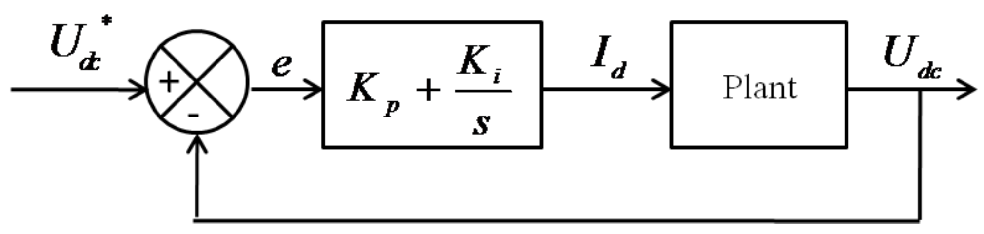
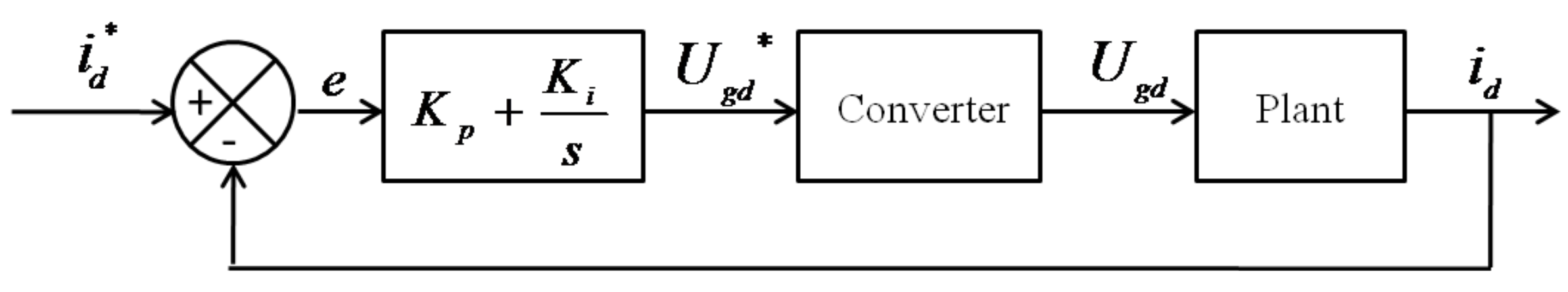
4.1. GSC DC-Link Control Design

The voltage oriented strategy is used to control the grid-connected inverter. The main objective is to maintain the exchange power to the generator with the grid [39]. The proposed scheme of the implemented control approach is shown in Figure 6.
In such a control scheme, a Phase Locked Loop (PLL) block is used to recover the phase of the input signal which, denotes θ g . The d-q axis currents and voltages are obtained using Park’s transformation.
The grid voltages (V) can be defined as follows:
U a g = i a g R g + L g d i a g d t + U a g 1 U b g = i b g R g + L g d i b g d t + U b g 1 U c g = i c g R g + L g d i c g d t + U c g 1
where R g ( Ω ) and L g (H) are the grid coupling resistance and inductance, respectively, U a g 1 , U b g 1 , U c g 1 (V) are the three phase converter terminal voltages and i a g , i b g , i c g (A) are the three phase grid currents. Using Park’s transformation, Equation (17) can be written in the d-q reference frame as follows:
U g d = i d s R g + L g d i d s d t - ω s L g i q s + U g d 1 U g q = i q s R g + L g d i q s d t - ω s L g i d s + U g q 1
According to Equations (14) and (15), the active and reactive power are controlled via the d-axis and q-axis current, respectively. The current control loops are identical and generate the grid voltage references U d s * and U q s * as:
U g d * = U g d + Ω g L g i q - ( K P i e d + K I i e d d t ) U g q * = U g q - Ω g L g i d - ( K P i e q + K I i e q d t )
where Ω g is the synchronous frequency (rad/s), K P i , K I i are the gains of the current Proportional Integral (PI) controller and e d , e q are the errors of the currents defined in the d-q reference frame, respectively. In order to enhance the transient response of the system, compensator terms and feed-forward voltage are added to the control signals [40]. Finally, the reference voltages transformed to the three-phase abc frame are then used to generate all PWM signals for the GSC.
There are three feedback control loops; one outer voltage loop for the control of DC voltage U d c and two inner currents loops for the control of the direct and quadrature axis currents i d s and i q s , respectively. i q s is used to regulate the reactive power. During normal operation, the converter will transfer all of the active power generated by the TST to the grid. Thus, the q-axis current reference is set to zero.
The outer voltage control loop generates the current reference for the inner current loop. The inner loop must be faster to ensure that there is no interaction with the outer voltage loop. Thus, the inner loop can be approximated as a unity gain [40]. The closed loop scheme of the DC-link voltage is shown in Figure 7.
Recalling Equation (16), the transfer function of the plant is expressed in the continuous domain as:
U d c ( s ) I d ( s ) = 3 4 m a C s
where m a is the modulation ratio and C is the capacitance in ( F ) .
The desired closed loop poles are characterized by their relative damping coefficient and their natural frequency. Assuring an overshoot of 5 % , the damping coefficient is 0 . 69 as given in [41]. The natural frequency ω 0 (rad/s) becomes a closed-loop performance parameter that is specified according to the desired closed-loop response requirement. From the simulation of a step response, the settling time is estimated as:
t s 5 ξ ω 0
The inner current control loop design is presented by Figure 8. The converter model is described by a delay of two sample periods.
The transfer function of the plant can be modeled by first order system, which is given by Equation (22). A third order closed loop of the current loop is defined.
1 L g s + R g
The design of the DC-link voltage and currents controllers are carried out using the experimental method of Ziegler-Nichols [42]. After obtaining the initial values of the gains, further refinement were introduced based on the robust response time algorithm [43].

4.2. RSC Rotational Speed Control Design

In order to capture the maximum power from tidal energy, we must permanently adjust the rotational speed of the turbine to the tidal velocity by means of the Rotor Side Converter (RSC). The maximum amount of energy extraction equals the 16/27th part of the kinetic energy in the current. This limit is often referred to as the Lanchester-Betz limit. Therefore, controlling the power coefficient by maintaining the tip speed ratio λ o p t at its optimal value is the main characteristic of the system [44]. For each tidal current speed, there is a certain rotational speed at which the power curve reaches its maximum value. All of these maxima compose what is known in the literature as the Optimal Regimes Characteristic (ORC) [45,46,47]. As shown in Figure 9, the maximum power for the turbine under study is P n = 1 . 5 MW at V n = 3 . 2 m / s .
Figure 10 shows how the turbine power varies with the rotational speed for different values of the pitch angle at the rated tidal speed V n . The maximum power is reached for β = 0 , and as β increases, the power decreases. This feature aims to avoid the TST mechanical overload when the tidal velocity is above the rated value.
The proposed stator flux control strategy applied to the RSC is presented in Figure 11. The measured parameters are the stator and rotor currents, the stator voltage and the rotor speed. The controller structure consists of two inner current loops and an outer rotational speed loop.
The speed control loop design is conceived using the Maximum Power Point Tracking (MPPT) approach to control the generator rotational speed via the RSC and must be adjusted to track the optimal reference given as follows:
ω r e f = λ o p t V R
Equation (23) was used to determine the reference speed ω r e f expressed in (rad/s) for the speed control loop, which defines a reference signal for the q-axis rotor current i q r * . The d-axis current reference i d r * is set to zero. The process will be controlled by a PI controller in the continuous domain; the transfer function of the plant model is retrieved from Equation (8). Similarly to the DC-link voltage controller for the GSC, the controller gains of the speed control loop are obtained using the experimental method of Ziegler-Nichols.
For the inner current control loops determine the d-q rotor voltage reference. The relationship between the rotor voltages (V) and the rotor currents (A) is as given in [34]:
U d r = R r i d r + σ L r d i d r d t U q r = R r i q r + σ L r d i q r d t
where σ is the leakage factor.
The current control loops are identical and generate the rotor voltage reference U d r * and U q r * as presented by Equation (25). Furthermore, decoupled terms are added to the rotor voltage references that will improve the transient response of the system [48].
U d r * = - ω s l i p σ L r i q r + ( K P i e d + K I i e d d t ) U q r * = ω s l i p ( L m i m + σ L r i d r ) + ( K P i e d + K I i e d d t )
where ω s l i p is the slip angular frequency (rad/s) and i m is the stator magnetizing current, which is considered constant.
The control scheme for the RSC currents loops are identical. The block diagram is similar to the one of the current loop for the GSC of Figure 8 and assuming that the current loop is faster than the outer speed loop. After analyzing the second order system, the step response analyses is used to assess the closed-loop performance of the PI controller. The quadrature components of the rotor voltage reference are transformed to the abc stationary frame to be imposed to the RSC through the PWM block.

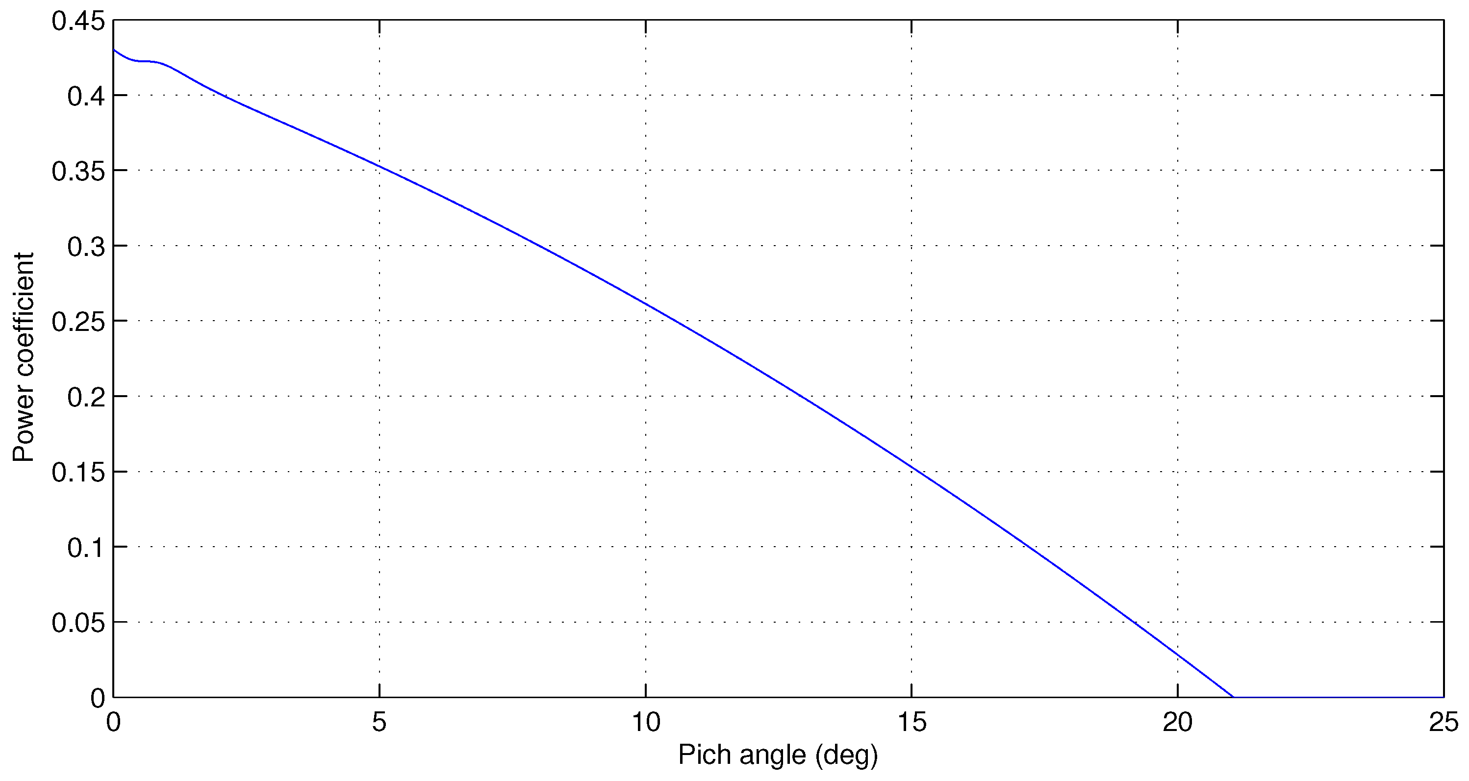
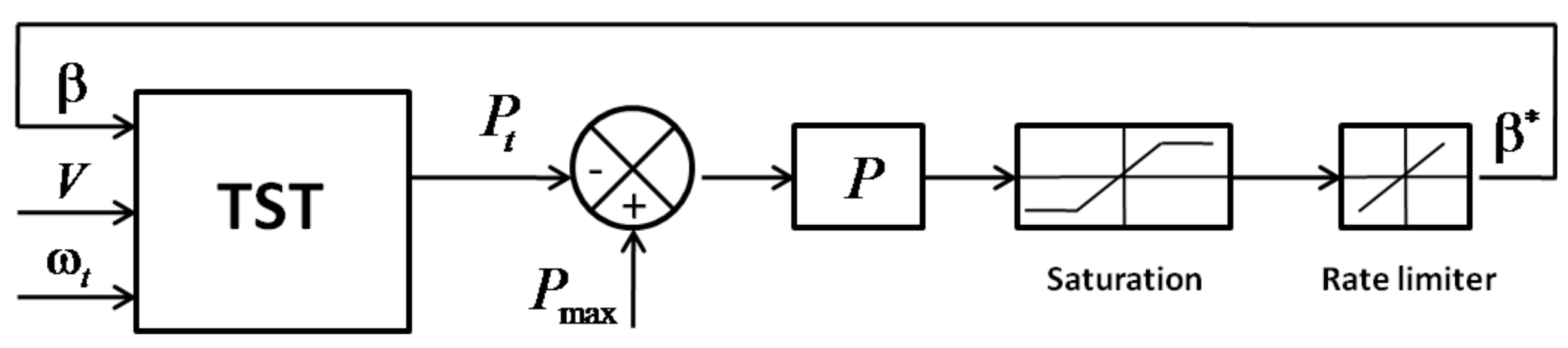
4.3. Pitch Angle Control

The control of the blade pitch is a useful method in order to avoid the generator overload when higher tidal speeds occur. A suitable pitch angle for stable operation can be generated by using the power error. To do so, the value of the pitch angle should increase when the turbine power is above the nominal value. In this mode of operation, the rotor rotational speed is maintained constant, and the turbine power is regulated by means of the pitch angle controller. The control scheme of the pitch angle controller is shown in Figure 12.
The pitch controller has the measured tidal turbine power P t and the power reference P max as inputs. P max is set to the maximum generator power, which is equal to 1 . 5 MW . A proportional controller is set to find the pitch angle β from the difference between P t and P max . Then, a saturation block is added to limit the value of β . As shown in Figure 13, the pitch angle can vary over the range of β = [ 0 , 21 ] . Moreover, the pitch angle’s variation over time is limited. As for wind turbines, the pitch angle rate can vary between 3 / s and 10 / s, as shown in [49]. For this study, the rate pitch angle used is about 10 / s for large turbine size.

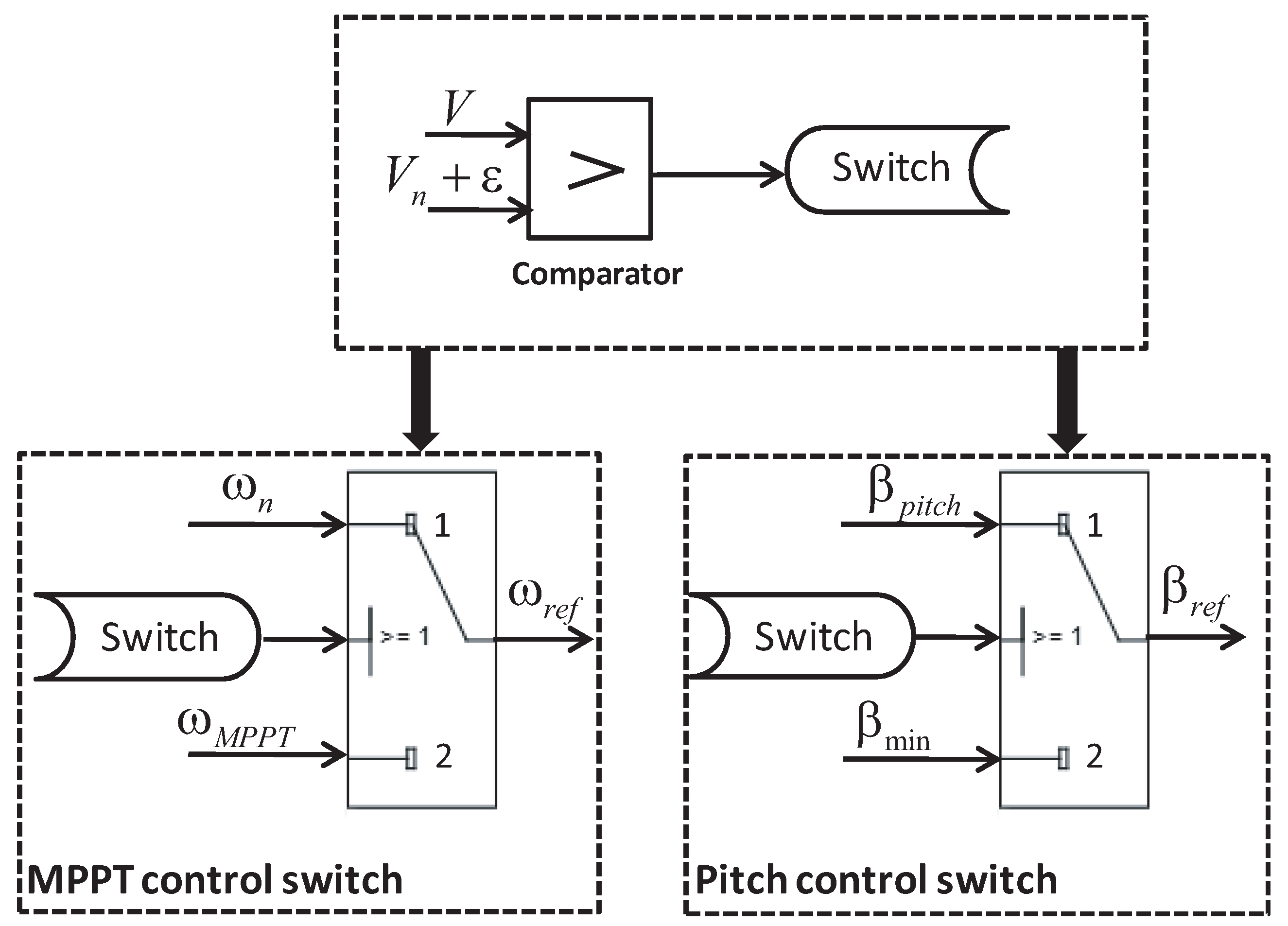
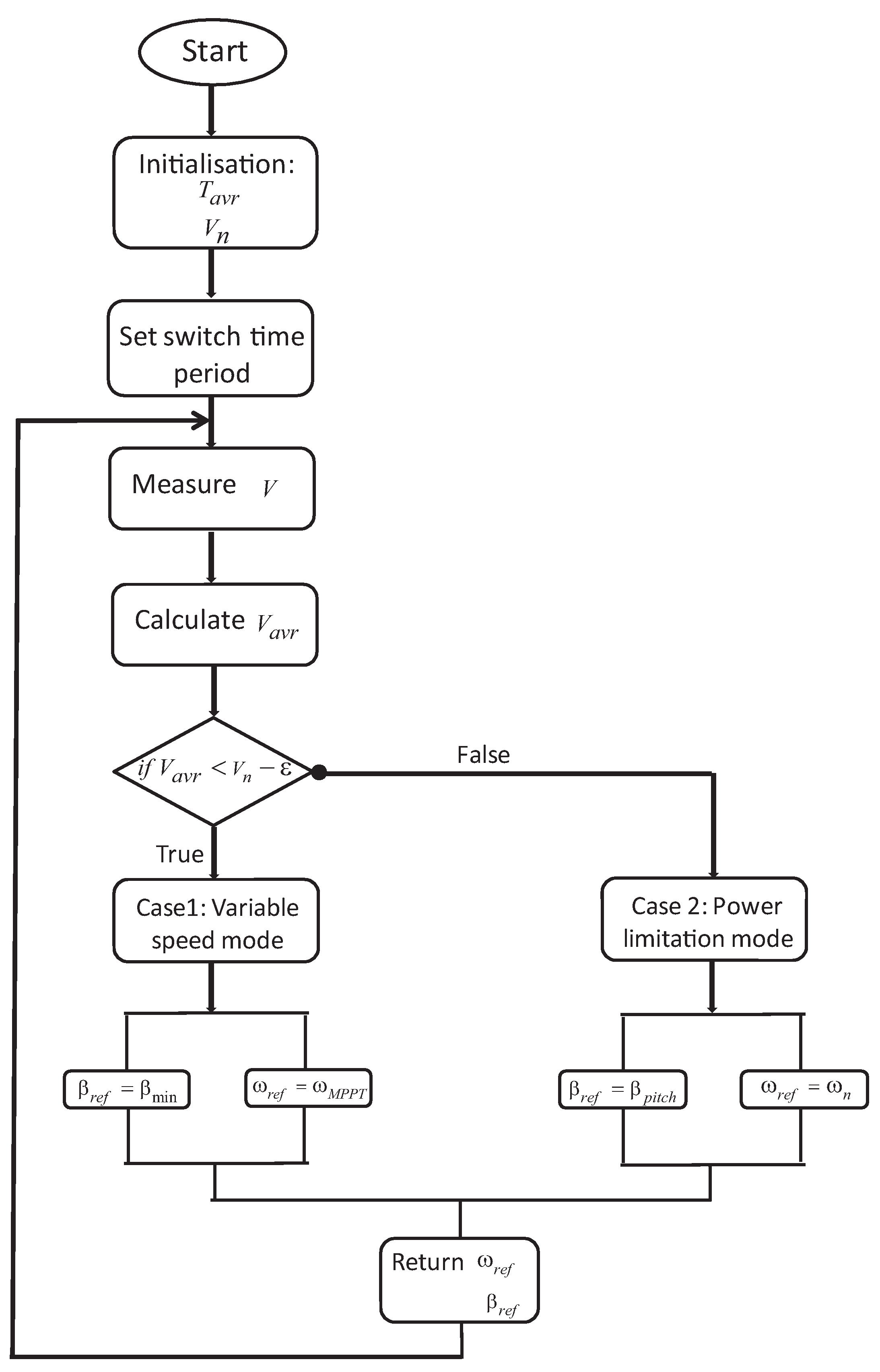
4.4. Complementary Control

The proposed complementary control consists of improving the performance and dynamic load assessment of the system under different operating conditions by adequately controlling the TST transition under and above the tidal current speed threshold value conditions. That is, the system is regulated so as to smoothly pass from the variable speed mode to the power limitation mode in order to optimize the generated output power. To do so, a switching algorithm is used. The variable speed and the power limitation modes are operating when the tidal velocity is under and above high flow speed, respectively. In the case of variable speed mode, the rotational speed control by means of the RSC is activated while keeping the pitch angle constant in order to drive the system to maximum power. In turn, when the tidal speed is high, the pitch angle control is activated to adequately rotate the blades at the suitable angular position and thus maintaining the rotational speed constant to successfully assure the power limitation. When the speed of the tide is within the limits of these regions, the system can pass from one mode to another often enough, which conducts supplementary stress to the pitch angle actuator.
The proposed novel switching control block is depicted in Figure 14, where ω n is the rated generator rotational speed, ω M P P T is the reference speed from the MPPT block and ω r e f is the reference rotational speed imposed on the RSC controller. The regulated pitch angle from the pitch controller block is denoted as β p i t c h , β m i n is setting null and β r e f is the value of the pitch angle reference, which is attributed to the pitch actuator.
In order to avoid frequent switching, we set a limit to the system as an interval ( V n - ε ) , ( V n + ε ) instead of a fixed value V n . ε represents the margin error of the measured tidal speed in order to ensure the protection of the turbine from overload. The comparator block compares V to V n over an average time period T a v r and if the condition V > ( V n + ε ) has been fulfilled, the switch variable changes to state 1 and the power limitation mode is triggered. Otherwise, if V < ( V n - ε ) , the switching variable passes to State 2, and the TST activates the variable speed operation mode. While the mean value of the tidal speed in an interval of length T a v r remains within the range | ( V n - ε ) , ( V n + ε ) | , the switch controller maintains the previous mode of operation.
The flowchart of the implemented switching control is shown in Figure 15. Indeed, when the tidal speed is in the boundary of the two regions of operation (variable speed and power limitation modes), the system can switch between these modes quite often, leading to extra stress of the pitch actuator. Therefore, the average of the tidal speed is calculated over a time period T a v r , the length of this period being the minimum time where the switch between modes can occur, to set a limit on how frequently the system crosses between operating modes.

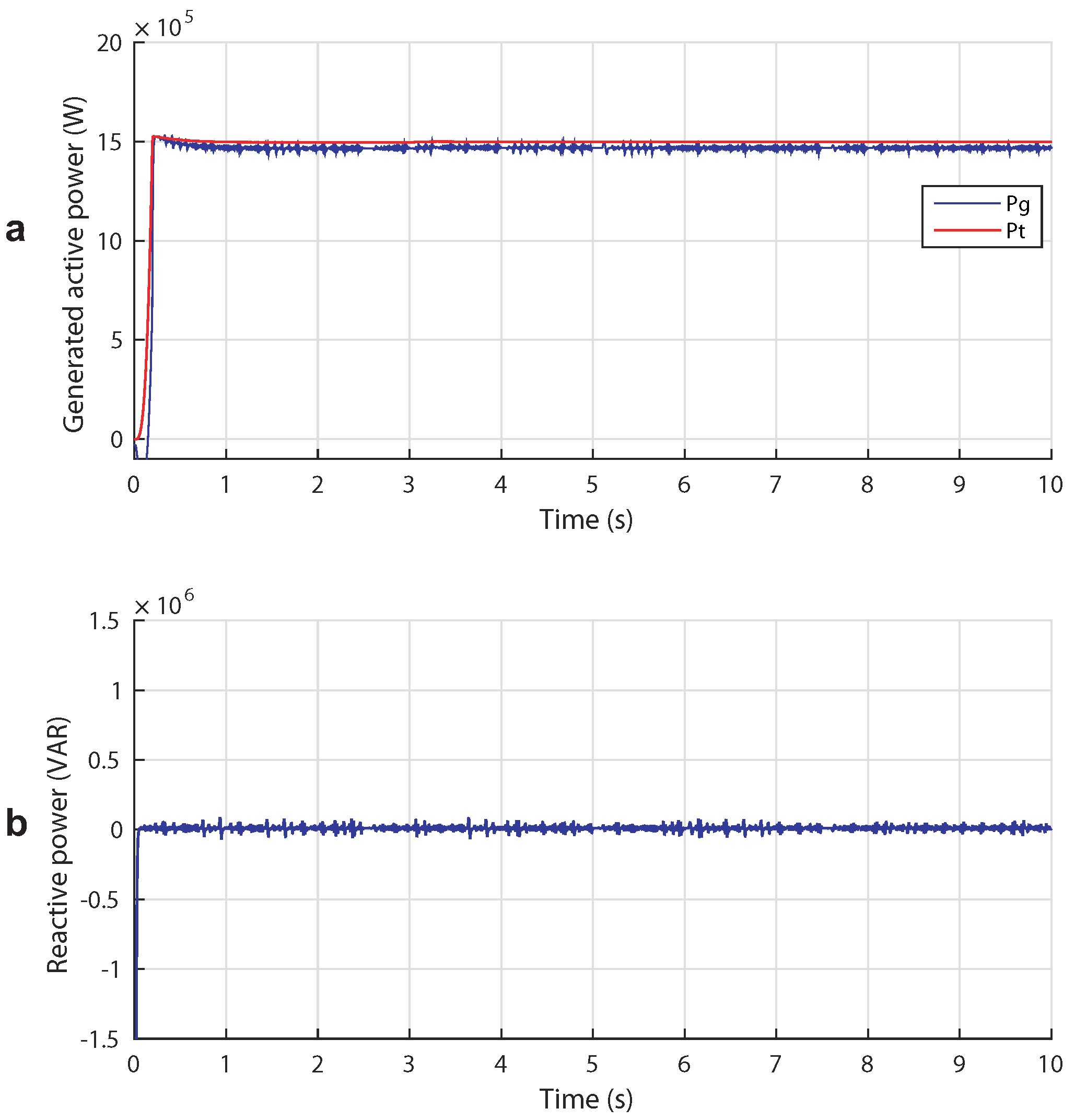
5. Results and Discussion

In this section, we will present three case studies to investigate the proposed control strategies. The input considered of the DFIG-based TST system is the tidal current speed, which is chosen in order to study the TST in different modes of operation. Recalling Figure 2 of Section 2, it may be observed that the given stream speed ranges allow testing and comparing the proposed control strategies for the different possible tidal scenarios. We used the system parameters listed in Table 1 in all cases.

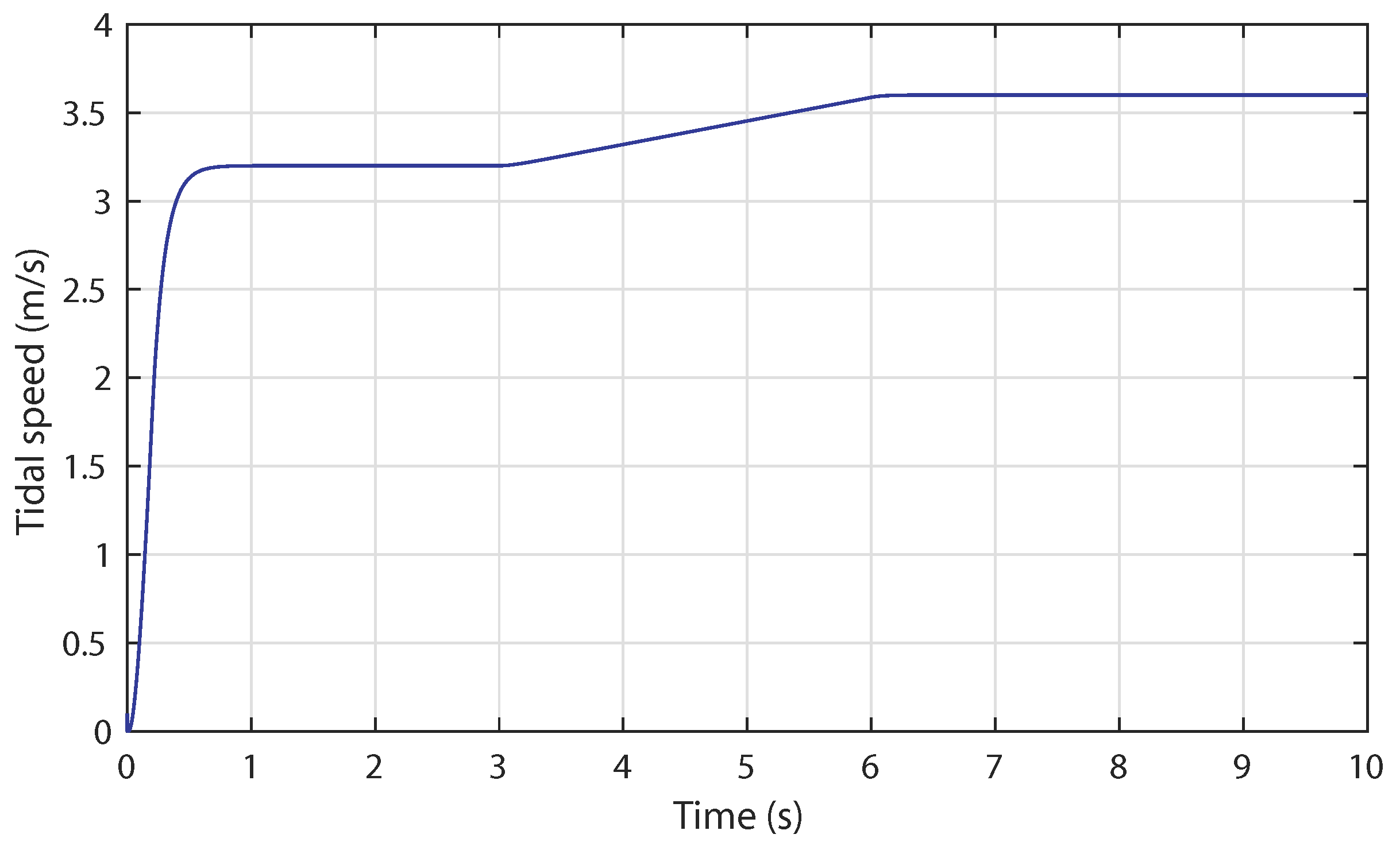
5.1. Case 1: Low Tidal Speed (Variable Speed Operation)

In this case, variable speed operation is achieved using the rotational speed control strategy. The turbine is operating below rated flow speeds; the rotor speed is being varied to maintain the optimal value of C p ; and the pitch angle was set to zero. Figure 16 shows that the turbine is initially operated at a tidal speed of 2 m / s .
At the simulation time t = 3 s , we mark a step change in the flow speed, which is applied from 2 m / s to 3 m / s . This causes a sudden variation in the hydrodynamic torque, which also has an impact on the generator torque, as shown in Figure 17a. The generated torque achieves a high value of 1 . 03 × 10 5 Nm for V = 3 m/s and a value of 4 . 58 × 10 4 Nm in the lower case when V = 2 m/s. The rotor rotational speed increases according to the flow speed input, as shown in Figure 17b. The control system performs well; thus, the rotational speed is able to track the reference signal generated from the MPPT block.
The purpose of this simulation case is to generate the maximum power from the turbine and transfer it to the grid. According to Figure 9, the MPPT control strategy works perfectly. Indeed, as may be seen in Figure 18a, the TST system is capable of maximizing the power output with 350 kW when V = 2 m / s , then increases at t = 3 s to 1.2MW when V = 3 m / s . Besides, the reactive power, as depicted in Figure 18b, is maintained at zero for unity power factor.

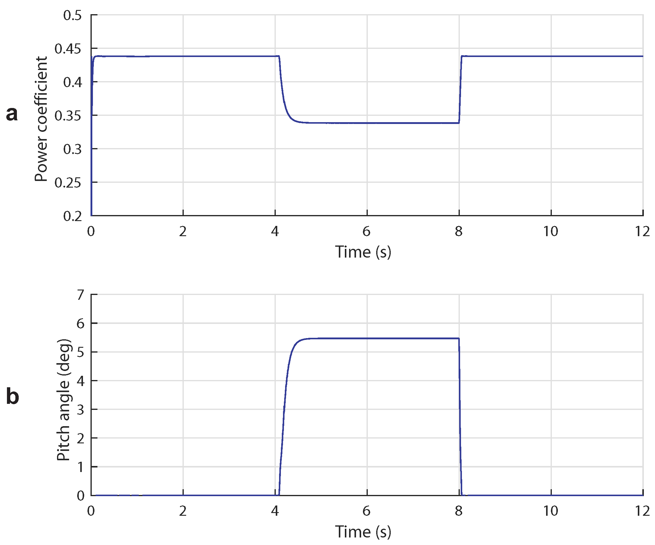
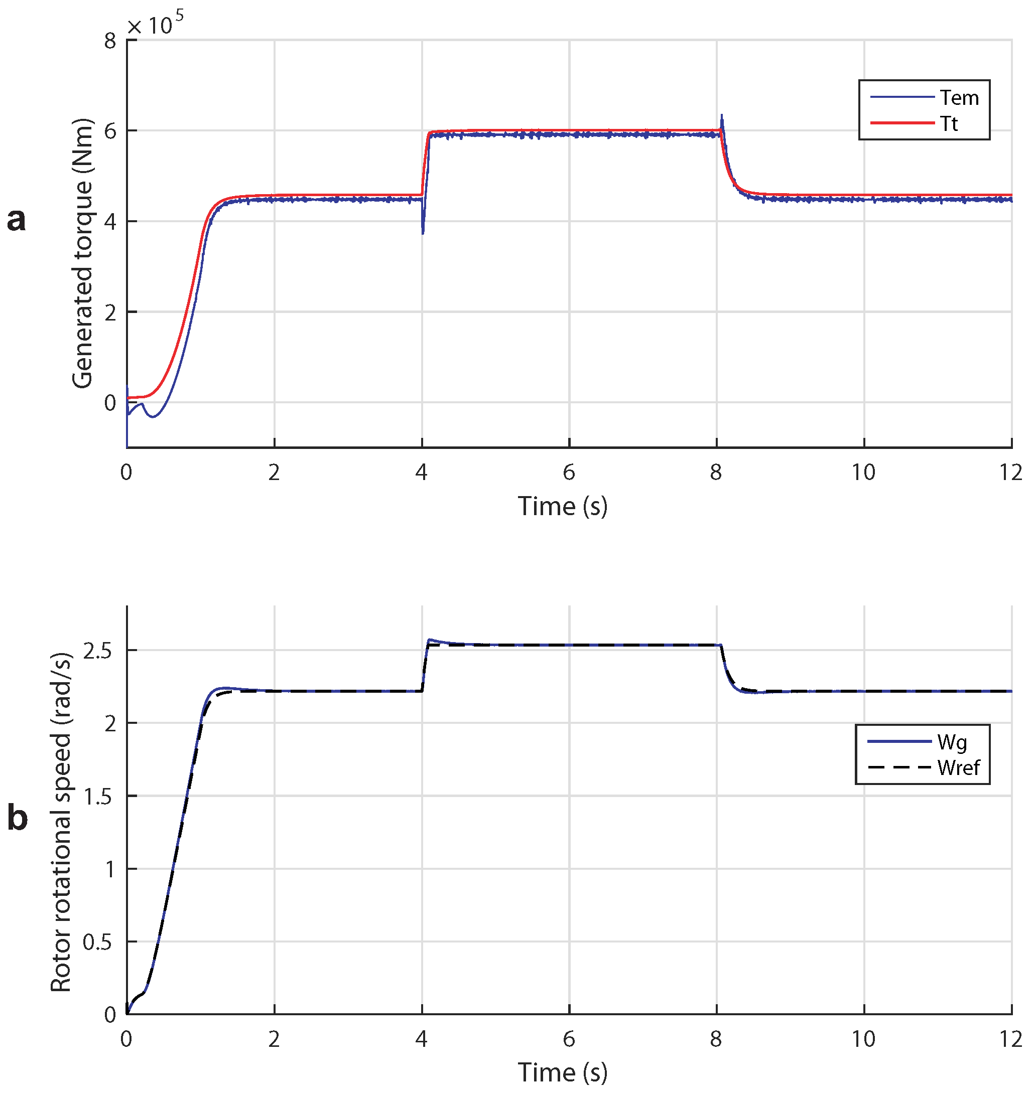
5.2. Case 2: High Tidal Speed (Power Limitation Mode)

In this case study, the pitch angle control is tested within the power limitation mode, which imposes an average tidal velocity over V n = 3 . 2 m / s . The tidal speed is stepped up from V n to V = 3 . 6 m / s at t = 3 s as shown in Figure 19.
The blade pitch angle β should increase to prevent the rotor speed from becoming too high, which would result in alleviation of intense mechanical loads, and consequently, the power coefficient should decrease as shown in Figure 20a,b. The responses of C p and β begin with a value of 0 . 44 and 0 deg, respectively, when V < V n - ε . Then, they achieve a value of 0 . 31 ° and 7 . 79 °, respectively, when V > V n + ε . The resulting hydrodynamic and electromagnetic torques are presented in Figure 21a. The value of the generated torque is limited to a value of 6 . 01 × 10 5 Nm when V exceeds the threshold value. The rotor rotational speed is maintained constant below the limit speed according to the reference signal from the switch controller as depicted in Figure 21b. The figure shows good tracking performances of the rotor speed.
Thus, as Figure 22a shows, the extracted power rises with the tidal step, then it is maintained at the rated power P n as the pitch angle β augments. The reactive power is kept oscillating around zero regardless of the change in tidal speed input, as shown in Figure 22b. We note that specifying a rated flow speed, at which the turbine produces its peak power and shedding power at low speeds in excess of the rated value, will increase the capacity factor of the turbine and reduce the cost per kWh of electricity generated.

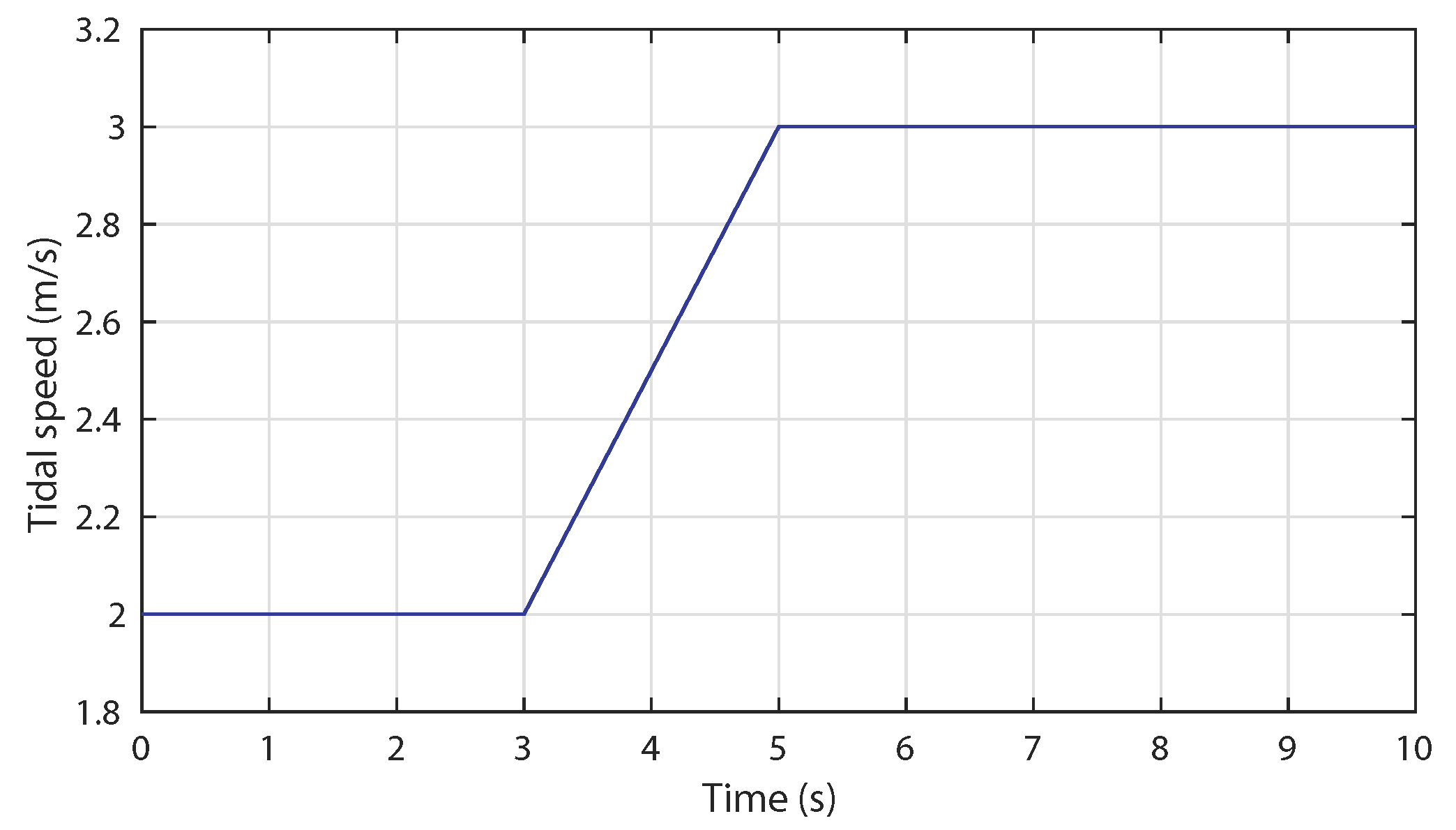
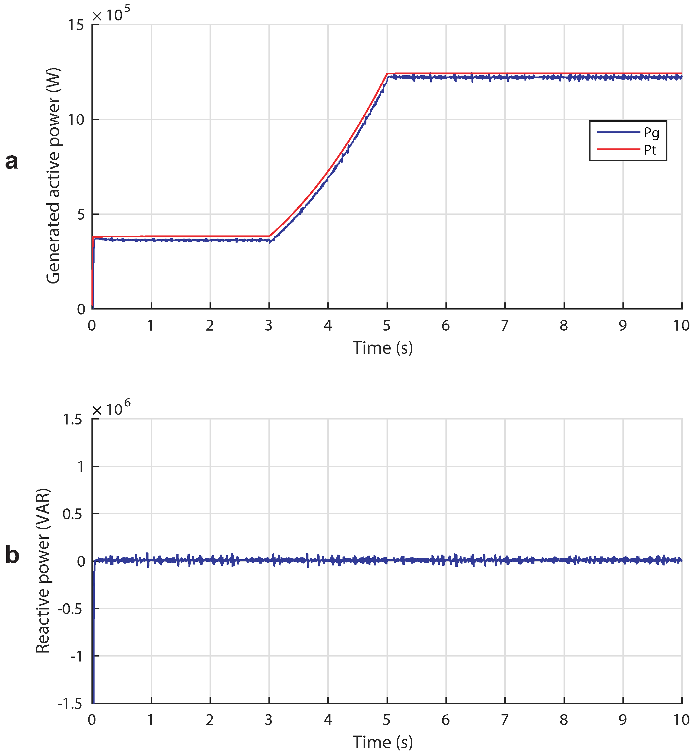
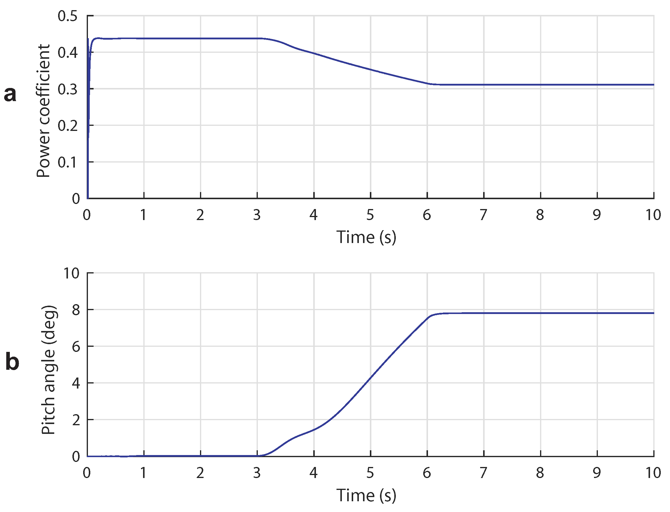
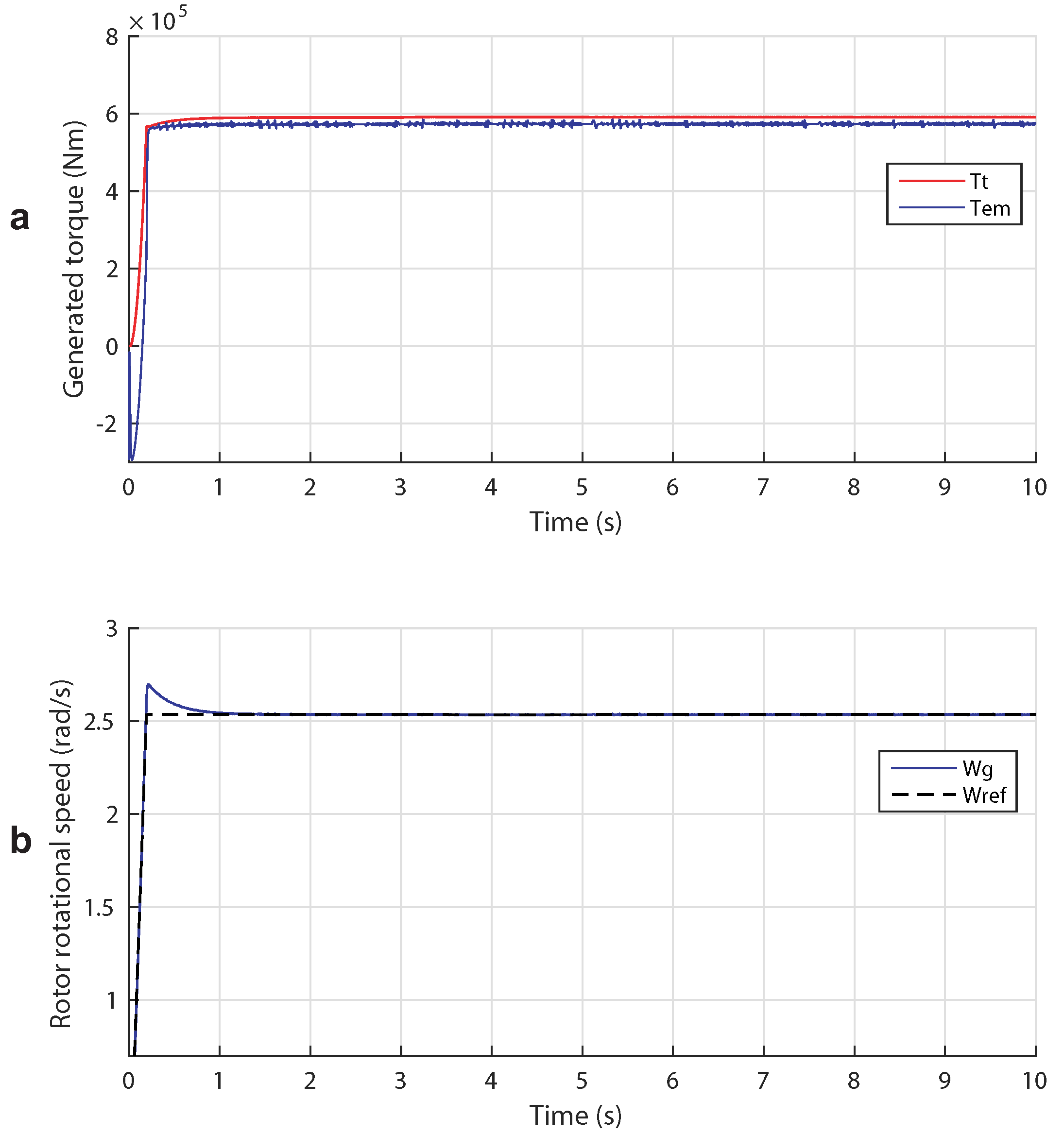
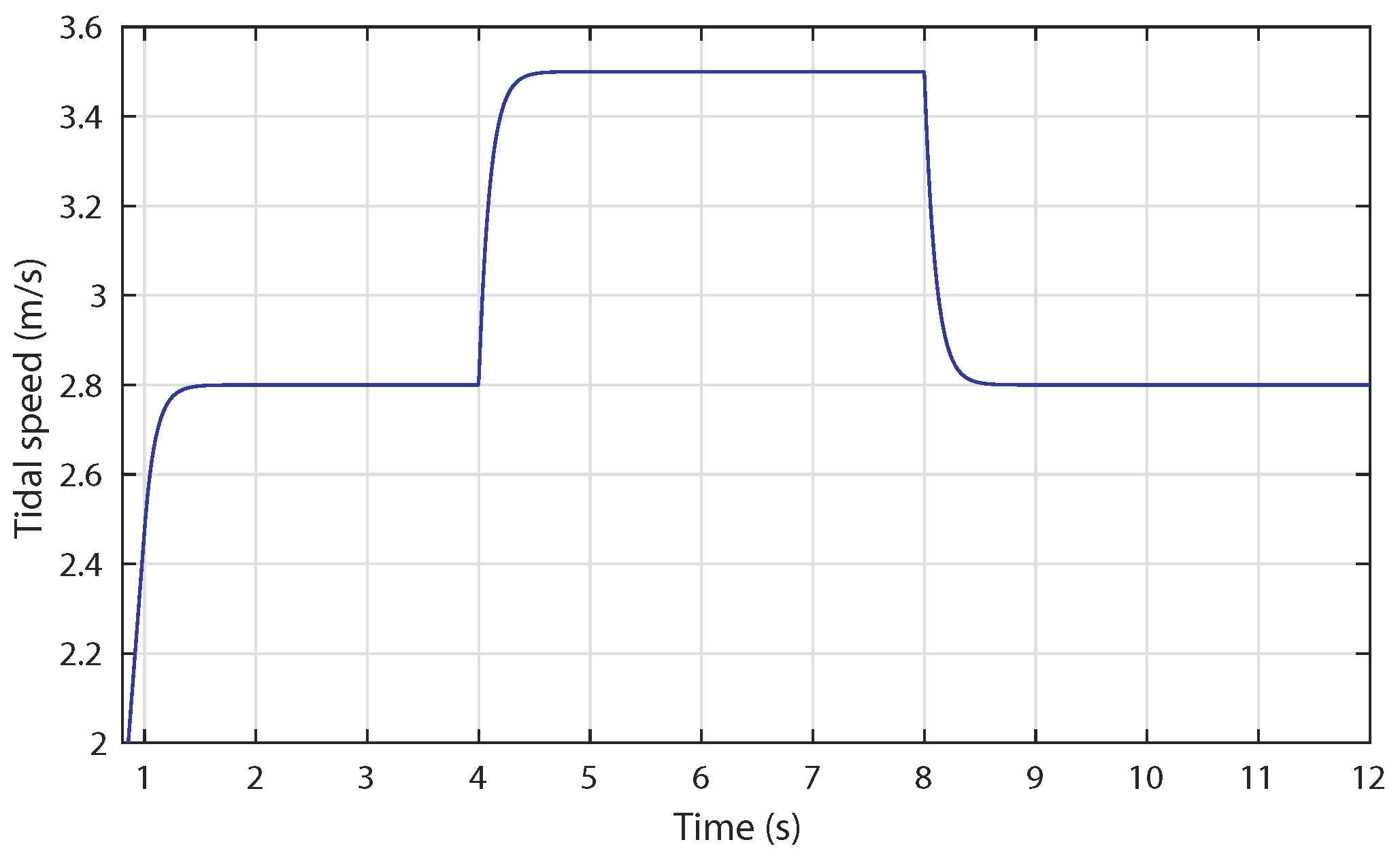
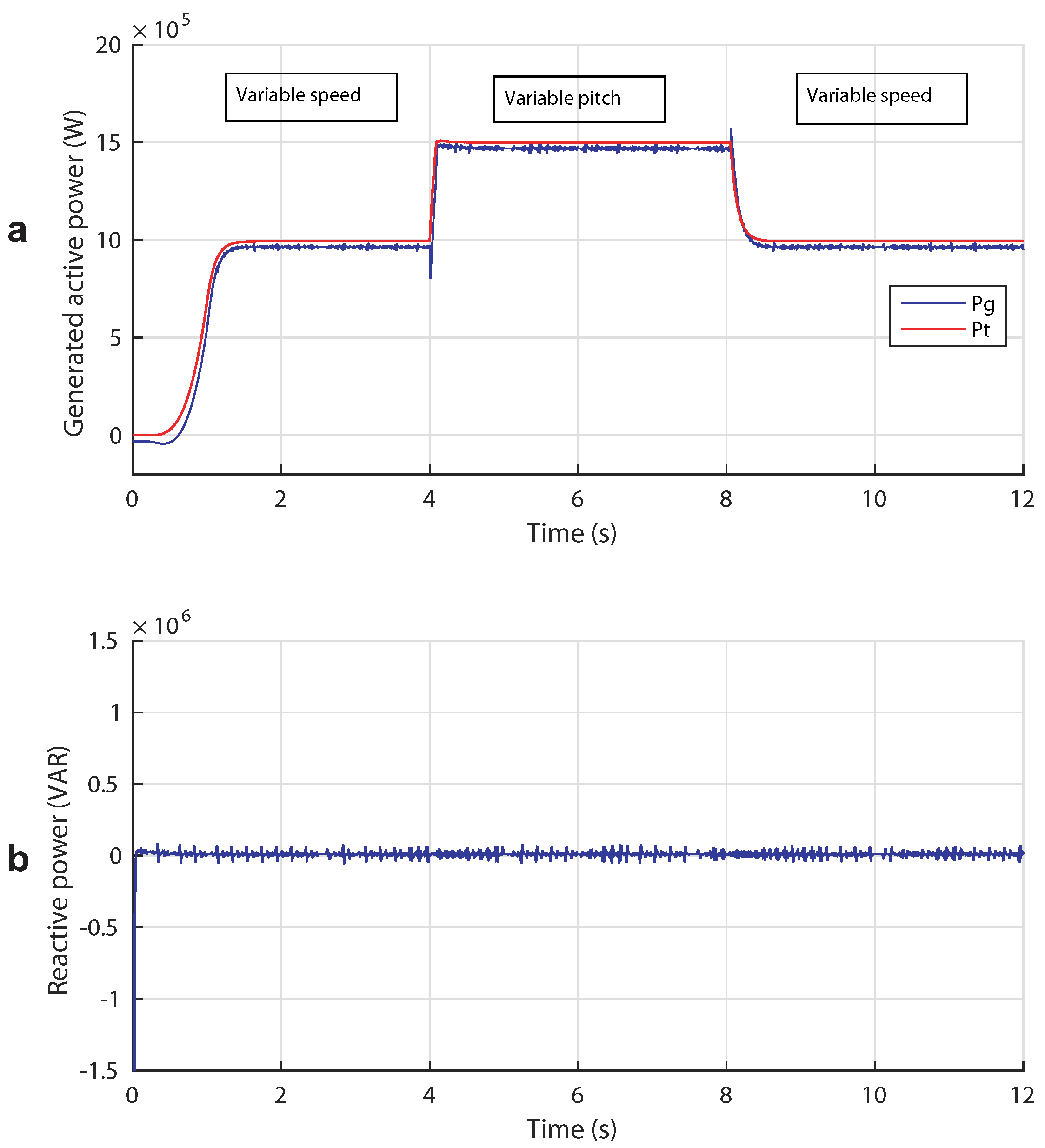
5.3. Case 3: Broad Tidal Speed Range (Complementary Control)

This case study examines the novel switching control between the functioning in variable speed and power limitation modes. The shape of the tidal speed input used in this case is depicted in Figure 23. Tidal speed steps from 2 . 8 m / s up to 3 . 5 m / s and then down again.
According to Figure 24, it can be concluded that the switching controller performs well because the power coefficient is maintained at its optimal value ( C p = 0 . 44 ) and then decreases as shown in Figure 24a. To the contrary, the pitch angle is kept null in the variable speed operation and rises accordingly to reach a value of the angular position of approximately ( β r e f = 5.5°) in the case of power limitation mode, as illustrated in Figure 24b.
The resulting hydrodynamic and generator torques are shown in Figure 25a. The generated torque admits a value of 4 . 57 × 10 5 Nm in the case of variable speed mode and a value of 6 . 01 × 10 5 Nm when V exceeds the tolerable value. Figure 25b depicts the rotor rotational speed, which is following the MPPT strategy to track the adequate rotational speed so that the maximum power is obtained. The rotational speed is kept constant to limit the power above nominal tidal speed.
The expected operating regions are labeled in Figure 26a which illustrates the generated power. In both the first and third regions, where the variable speed mode is used, the power is maximized to 955 . 1 kW ; whereas, in the second region, the variable pitch control is set limiting the maximum power to 1 . 43 MW . However, the switching within the two modes does not occur immediately due to the time response of the switch controller. We note that the power increases below the rated tidal speed, but it decreases, at high tidal speed, as the rate limiter forces β to increase. The blades take about 0.5 s to reach the desired value. The reactive power transferred to the grid, as shown in Figure 26b, is held around zero.

6. Conclusions

This paper dealt with the modeling and control of a DFIG-based TST system connected to the grid through a back-to-back power converter. The common problem with TST is the low power generated at low tidal speed and the excess power at high tidal speed. In this sense, two control strategies were proposed for both cases, and a novel complementary control combining both approaches was implemented.
When the flow speed is below the rated value, a control scheme that maximizes the power output of the TST by allowing the rotor speed to be varied has been developed and evaluated. Stator flux-oriented control was used for the RSC, and variable-speed operation of the rotor is achieved using the generator rotational speed. An MPPT strategy is used to track the optimum rotational speed in order to achieve the maximum power. On the grid-side, the voltage-oriented control scheme was used. The performance of the system was successfully implemented. When tested for a step change in the tidal speed, the RSC adequately varies the rotational speed, improving power extraction, whereas the GSC regulated the flow of active power to the grid, as well as controlling the flow of reactive power. Above the rated tidal current speed, a pitch angle control was investigated to limit the generated power. The switching control was tested among the operations in the variable-speed and power limitation modes. It may be seen that this complementary control presents an improved performance since it prevents frequent transitions when the power generated is at the limits of the two operation modes. Furthermore, the sensitivity of the proposed control strategies was analyzed regarding different tidal speed ranges. The controllers, designed to satisfy a predefined set of criteria, provide a satisfactory performance and are able to optimize the power output from the tidal stream generator system.
Three case studies were proposed to test the performance of both control strategies separately, then combined. The obtained results show that the proposed controls provide output power performance improvement in different operating modes.

Acknowledgments

This work was supported in part by the University of the Basque Country (Universidad del Pais Vasco UPV/ Euskal Herriko Unibertsitatea EHU) through Project PPG17/33 and by the MINECO through the Research Project DPI2015-70075-R (MINECO/FEDER, EU). (Ministerio de Economa, Industria y Competitividad/Fondo Europeo de Desarrollo Regional, European Union). The authors would like also to thank the anonymous reviewers for the useful comments that have helped to improve the initial version of this manuscript.

Author Contributions

All authors contributed to the modeling and implementation of the entire system. Khaoula Ghefiri developed the control strategies and analyzed the results with guidance from Izaskun Garrido and Aitor J. Garrido. All authors collaborated to prepare the manuscript.

Conflicts of Interest

The authors declare no conflict of interest.

References

  1. Kempener, R.; Neumann, F. IRENA Ocean Energy Tech Brief 3; Tidal Energy Technology Brief; IRENA: Abu Dhabi, UAE, 2014. [Google Scholar]
  2. Ocean Energy Forum. Draft Ocean Energy Strategic Roadmap Building Ocean Energy For Europe; Technical Report; European Commission: Brussels, Belgium, 2015. [Google Scholar]
  3. European Commission. Ocean Energy Europe and TP Ocean; Issue Paper on Ocean Energy Industry Response; European Commission: Brussels, Belgium, 2016. [Google Scholar]
  4. Hess, H.L.; Abdul Melek, N.A.; Muljadi, E. Power converter for wind turbine application. In Proceedings of the 2000 IEEE Power Engineering Society Summer Meeting, Washington, DC, USA, 16–20 July 2000; Volume 2, pp. 1275–1276. [Google Scholar]
  5. Blaabjerg, F.; Iov, F.; Terekes, T.; Teodorescu, R. Power electronics-key technology for renewable energy systems. In Proceedings of the 2011 2nd Power Electronics, Drive Systems and Technologies Conference (PEDSTC), Tehran, Iran, 16–17 February 2011; pp. 445–466. [Google Scholar]
  6. Zhou, D.; Blaabjerg, F.; Lau, M.; Tonnes, M. Optimized reactive power flow of DFIG power converters for better reliability performance considering grid codes. IEEE Trans. Ind. Electron. 2015, 62, 1552–1562. [Google Scholar] [CrossRef]
  7. Hu, J.; Nian, H.; Xu, H.; He, Y. Dynamic modeling and improved control of DFIG under distorted grid voltage conditions. IEEE Trans. Energy Convers. 2011, 26, 163–175. [Google Scholar] [CrossRef]
  8. Blaabjerg, F.; Liserre, M.; Ma, K. Power Electronics Converters for Wind Turbine Systems. IEEE Trans. Ind. Appl. 2012, 48, 708–719. [Google Scholar] [CrossRef]
  9. Magagna, D.; Uihlein, A. 2014 JRC Ocean Energy Status Report; Joint Research Centre Institute for Energy and Transport: Luxembourg, 2015. [Google Scholar]
  10. Bae, Y.H.; Kim, K.O.; Choi, B.H. Lake Sihwa tidal power plant project. Ocean Eng. 2010, 37, 454–463. [Google Scholar] [CrossRef]
  11. Milne, I.A.; Sharma, R.N.; Flay, R.G.J.; Bickerto, S. The role of onset turbulence on tidal turbine blade loads. In Proceedings of the 17th Australasian Fluid Mechanics Conference, Auckland, New Zealand, 5–9 December 2010. [Google Scholar]
  12. Filipot, J.F.; Prevosto, M.; Maisondieu, C.; Le Boulluec, M.; Thomson, J. Wave and turbulence measurements at a tidal energy site. In Proceedings of the 2015 IEEE/OES Eleventh Current, Waves and Turbulence Measurement (CWTM), St Petersburg, FL, USA, 2–6 March 2015; pp. 1–9. [Google Scholar]
  13. Bouaziz, B.; Bacha, F.; Gasmi, M. Variable Switching Frequency Direct Power Control based on Sliding Mode approach for grid connected voltage source converters. In Proceedings of the 15th International Conference on Sciences and Techniques of Automatic Control and Computer Engineering (STA), Hammamet, Tunisia, 21–23 December 2014; pp. 878–883. [Google Scholar]
  14. Khaligh, A.; Onar, O.C. Energy Harvesting: Solar, Wind, and Ocean Energy Conversion Systems; CRC Press: Boca Raton, FL, USA, 2009; pp. 1–382. [Google Scholar]
  15. Benelghali, S.; Benbouzid, M.E.H.; Charpentier, J.F. Generator systems for marine current turbine applications: A comparative study. IEEE J. Ocean. Eng. 2012, 37, 554–563. [Google Scholar] [CrossRef]
  16. Jahromi, M.J.; Maswood, A.I.; Tseng, K.J. Design and evaluation of a new converter control strategy for near-shore tidal turbines. IEEE Trans. Ind. Electron. 2013, 60, 5648–5659. [Google Scholar] [CrossRef]
  17. Liu, C.; Xu, D.; Zhu, N.; Blaabjerg, F.; Chen, M. DC-voltage fluctuation elimination through a DC-capacitor current control for DFIG converters under unbalanced grid voltage conditions. IEEE Trans. Power Electron. 2013, 28, 3206–3218. [Google Scholar]
  18. Ben Elghali, S.E.; Benbouzid, M.E.H.; Charpentier, J.F. Modeling and Control of a Marine Current Turbine Driven Doubly-Fed Induction Generator. IET Renew. Power Gener. 2010, 4, 1–11. [Google Scholar] [CrossRef]
  19. Whitby, B.; Ugalde-Loo, C.E. Performance of Pitch and Stall Regulated Tidal Stream Turbines. IEEE Trans. Sustain. Energy 2014, 5, 64–72. [Google Scholar] [CrossRef]
  20. Wang, L.; Hsiung, C.T. Dynamic stability improvement of an integrated grid-connected offshore wind farm and marine-current farm using a STATCOM. IEEE Trans. Power Syst. 2011, 26, 690–698. [Google Scholar] [CrossRef]
  21. Kirke, B.K.; Lazauskas, L. Limitations of fixed pitch Darrieus hydrokinetic turbines and the challenge of variable pitch. Renew. Energy 2011, 36, 893–897. [Google Scholar] [CrossRef]
  22. Ben Elghali, S.E.; Balme, R.; Le Saux, K.; Benbouzid, M.E.H.; Charpentier, J.F.; Hauville, F. A Simulation Model for the Evaluation of the Electrical Power Potential Harnessed by a Marine Current Turbine. IEEE J. Ocean. Eng. 2007, 32, 786–797. [Google Scholar] [CrossRef]
  23. Ghefiri, K.; Bouallègue, S.; Haggège, J. Modeling and SIL simulation of a Tidal Stream Device for Marine Energy Conversion. In Proceedings of the 6th International Renew. Energy Congress (IREC) IEEE, Sousse, Tunisia, 24–26 March 2015; pp. 1–6. [Google Scholar]
  24. Ben Elghali, S.E.; Benbouzid, M.E.H.; Charpentier, J.F.; Tarek, A.A.; Munteanu, I. Experimental Validation of a Marine Current Turbine Simulator: Application to a Permanent Magnet Synchronous Generator-Based System Second-Order Sliding Mode Control. IEEE Trans. Ind. Electron. 2011, 58, 118–126. [Google Scholar] [CrossRef]
  25. Ben Elghali, S.E.; Benbouzid, M.E.H.; Charpentier, J.F. Marine Tidal Current Electric Power Generation Technology: State of the Art and Current Status. In Proceedings of the IEEE International Electric Machines and Drives Conference, Antalya, Turkey, 21–24 May 2007; Volume 2, pp. 1407–1412. [Google Scholar]
  26. Grifoll, M.; Fontan, A.; Ferrer, L.; Mader, J.; Gonzalez, M.; Espino, M. 3D hydrodynamic characterisation of a meso-tidal harbour: The case of Bilbao (northern Spain). Coast. Eng. 2009, 56, 907–918. [Google Scholar] [CrossRef]
  27. Hammons, T.J. Tidal power. Proc. IEEE 1993, 81, 419–433. [Google Scholar] [CrossRef]
  28. Bryden, I.G.; Grinsted, T.; Melville, G.T. Assessing the potential of a simple tidal channel to deliver useful energy. Appl. Ocean Res. 2004, 26, 198–204. [Google Scholar] [CrossRef]
  29. Bryden, I.G.; Couch, S.J. ME1-marine energy extraction: Tidal resource analysis. Renew. Energy 2006, 31, 133–139. [Google Scholar] [CrossRef]
  30. Myers, L.E.; Bahaj, A.S. Power output performance characteristics of a horizontal axis marine current turbine. Renew. Energy 2006, 31, 197–208. [Google Scholar] [CrossRef]
  31. Wang, L.; Li, C.N. Dynamic Stability Analysis of a Tidal Power Generation System Connected to an Onshore Distribution System. IEEE Trans. Energy. Convers. 2011, 26, 1191–1197. [Google Scholar] [CrossRef]
  32. Fernandez, L.M.; Jurado, F.; Saenz, J.R. Aggregated dynamic model for wind farms with doubly fed induction generator wind turbines. Renew. Energy 2008, 33, 129–140. [Google Scholar] [CrossRef]
  33. Alberdi, M.; Amundarain, M.; Garrido, A.J.; Garrido, I.; Casquero, O.; De la Sen, M. Complementary Control of Oscillating Water Column-Based Wave Energy Conversion Plants to Improve the Instantaneous Power Output. IEEE Trans. Energy Convers. 2011, 26, 1021–1032. [Google Scholar] [CrossRef]
  34. Amundarain, M.; Alberdi, M.; Garrido, A.J.; Garrido, I. Modeling and Simulation of Wave Energy Generation Plants: Output Power Control. IEEE Trans. Ind. Electron. 2011, 58, 105–117. [Google Scholar] [CrossRef]
  35. Carrasco, J.M.; Franquelo, L.G.; Bialasiewicz, J.T.; Galván, E.; Guisado, R.P.; Prats, M.A.M.; León, J.I.; Moreno-Alfonso, N. Power-electronic systems for the grid integration of renewable energy sources: A survey. IEEE Trans. Ind. Electron. 2006, 53, 1002–1016. [Google Scholar] [CrossRef]
  36. Pena, R.; Clare, J.C.; Asher, G.M. Doubly fed induction generator using back-to-back PWM converters and its application to variable speed wind-energy generation. IEE Proc. Electr. Power Appl. 1996, 143, 231–241. [Google Scholar] [CrossRef]
  37. Alberdi, M.; Amundarain, M.; Garrido, A.J.; Garrido, I.; Maseda, F.J. Fault-Ride-Through Capability of Oscillating-Water-Column-Based Wave-Power-Generation Plants Equipped With Doubly Fed Induction Generator and Airflow Control. IEEE Trans. Ind. Electron. 2011, 58, 1501–1517. [Google Scholar] [CrossRef]
  38. Alberdi, M.; Amundarain, M.; Garrido, A.J.; Garrido, I. Neural control for voltage dips ride-through of oscillating water column-based wave energy converter equipped with doubly-fed induction generator. Renew. Energy 2012, 48, 16–26. [Google Scholar] [CrossRef]
  39. Nunes, M.V.A.; Pecas, J.A.; Zurn, H.H.; Bezerra, U.H.; Almeida, R.G. Influence of the variable-speed wind generators in transient stability margin of the conventional generators integrated in electrical grids. IEEE Trans. Energy Convers. 2004, 19, 692–701. [Google Scholar] [CrossRef]
  40. Blaabjerg, F.; Teodorescu, R.; Liserre, M.; Timbus, A.V. Overview of Control and Grid Synchronization for Distributed Power Generation Systems. IEEE Trans. Power Electron. 2006, 53, 1398–1409. [Google Scholar] [CrossRef]
  41. Astrom, K.J.; Hagglund, T. PID Controllers: Theory, Design and Tuning, 2nd ed.; ISA: Research Triangle Park, NC, USA, 1995. [Google Scholar]
  42. Astrom, K.J.; Hagglund, T. Advanced PID Control; ISA-The Instrumentation, Systems and Automation Society: Research Triangle Park, NC, USA, 2006. [Google Scholar]
  43. Vilanova, R.; Visioli, A. PID Control in the Third Millennium; Springer: London, UK, 2012. [Google Scholar]
  44. Benelghali, S.; Benbouzid, M.; Charpentier, J.F.; Ahmed-Ali, T.; Gahery, J.M.; Denis, A. Modeling and MPPT Sensorless Control of a DFIG-Based Marine Current Turbine. In Proceedings of the 2008 18th International Conference on Electrical Machines (ICEM), Vilamoura, Portugal, 6–9 September 2008; Volume 2, pp. 1–6. [Google Scholar]
  45. Munteanu, I.; Bratcu, A.I.; Cutululis, N.A.; Ceanga, E. Optimal Control of Wind Energy Systems: Towards a Global Approach; Springer: London, UK, 2008; ISBN 978-1-84800-079-7. [Google Scholar]
  46. Multon, B. Marine Renewable Energy Handbook; John Wiley & Sons: Hoboken, NJ, USA, 2013. [Google Scholar]
  47. Harries, T.; Kwan, A.; Brammer, J.; Falconer, R. Physical testing of performance characteristics of a novel drag-driven vertical axis tidal stream turbine; with comparisons to a conventional Savonius. Int. J. Mar. Energy 2016, 14, 215–228. [Google Scholar] [CrossRef]
  48. Twining, E.; Holmes, D.G. Grid Current Regulation of a Three-Phase Voltage Source Inverter with an LCL Input Filter. IEEE Trans. Power Electron. 2003, 18, 888–895. [Google Scholar] [CrossRef]
  49. Slootweg, J.G.; Polinder, H.; Kling, W.L. Dynamic modelling of a wind turbine with doubly fed induction generator. In Proceedings of the 2001 IEEE Power Engineering Society Summer Meeting, Vancouver, BC, Canada, 15–19 July 2008; Volume 1, pp. 644–649. [Google Scholar]
Figure 1. Effect of the Sun and the Moon on the tides.
Energies 10 00862 g001
Figure 2. Tidal velocity variation per hour.
Energies 10 00862 g002
Figure 3. Flux density versus current speed.
Energies 10 00862 g003
Figure 4. General scheme for a DFIG-based TST system.
Energies 10 00862 g004
Figure 5. System control description.
Energies 10 00862 g005
Figure 6. Voltage-oriented control structure for the Grid Side Converter (GSC).
Energies 10 00862 g006
Figure 7. Outer DC-link voltage loop design.
Energies 10 00862 g007
Figure 8. Inner current control loop design.
Energies 10 00862 g008
Figure 9. Power versus rotational speed for different tidal speeds.
Energies 10 00862 g009
Figure 10. Power versus rotational speed for different pitch angles at rated tidal speed.
Energies 10 00862 g010
Figure 11. Stator flux-oriented control structure for the Rotor Side Converter (RSC).
Energies 10 00862 g011
Figure 12. Block diagram of the pitch controller.
Energies 10 00862 g012
Figure 13. Power coefficient versus pitch angle.
Energies 10 00862 g013
Figure 14. Block diagram of the switch controller.
Energies 10 00862 g014
Figure 15. Flowchart of the switching algorithm.
Energies 10 00862 g015
Figure 16. Tidal speed input: Case Study 1.
Energies 10 00862 g016
Figure 17. Case Study 1: (a) responses of the hydrodynamic and generator torques to a step change in tidal speed; (b) rotor rotational speed curve and its reference.
Energies 10 00862 g017
Figure 18. Case Study 1: (a) generated turbine and generator power curves; (b) reactive power curve.
Energies 10 00862 g018
Figure 19. Tidal speed input: Case Study 2.
Energies 10 00862 g019
Figure 20. Case Study 2: (a) power coefficient curve; (b) pitch angle response.
Energies 10 00862 g020
Figure 21. Case Study 2: (a) responses of the hydrodynamic and generator torques; (b) rotor rotational speed curve and its reference.
Energies 10 00862 g021
Figure 22. Case Study 2: (a) generated turbine and generator power curves; (b) reactive power curve.
Energies 10 00862 g022
Figure 23. Tidal speed input: Case Study 3.
Energies 10 00862 g023
Figure 24. Case Study 3: (a) power coefficient curve; (b) pitch angle response.
Energies 10 00862 g024
Figure 25. Case Study 3: (a) responses of the hydrodynamic and generator torques; (b) rotor rotational speed curve and its reference.
Energies 10 00862 g025
Figure 26. Case Study 3: (a) generated turbine and generator power curves; (b) reactive power curve.
Energies 10 00862 g026
Table 1. System parameters.
TurbineDrive-TrainDFIGConverter
ρ = 1027 kg/m3 H t = 3 s P n = 1.5 MW V d c = 1150 V
R = 8 m H g = 0 . 5 s U r m s = 690 VC = 0.01 F
C p max = 0 . 44 K s h = 2 × 10 6 Nm/rad f r e q = 50 Hz
λ o p t = 6 . 96 D s h = 3 . 5 × 10 5 Nms/rad R s = 2.63 m Ω
V n = 3.2 m/s R r = 2.63 m Ω Choke
L s = 0.168 mH R g =0.595 m Ω
L r = 0.133 mH L g = 0.157 mH
L m = 5.474 mH
p = 2

