1. Introduction
Offshore wind turbines are a new frontier in wind power development. Their foundations are significantly affected by the horizontal force and large bending moment at the top. Considering the mechanical properties, cost-effectiveness, and construction feasibility, the main forms of offshore wind turbine structures usually consist of concrete structures, such as elevated pile caps, monopile foundations, and gravity foundations. Bucket foundations are a new type of foundation currently used in offshore wind power construction. They are also called suction anchors, because they used to be applied to the mooring system as a suction pile. The bucket foundation looks like an inverted cup that is closed at the top and opened at the bottom. Steel bulkheads divide the seven rooms inside the composite bucket foundation (CBF). Hence, it is a relatively special construction layout, whose main mechanism is based on the principle of negative pressure penetration.
In recent years, studies on bucket foundations have been carried out in China and abroad. Helfrich et al. [
1] first carried out a model test in sand to study the characteristics and failure modes of suction anchors, and provided test data associated with a 400-mm diameter suction anchor. Le et al. [
2] presented the bearing capacities of bucket foundations in normally consolidated uniform clay under undrained conditions, and reported that the vertical capacity consisted of an end-bearing resistance and a skin friction resistance, whereas the horizontal capacity consisted of a normal resistance, a radial shear resistance, and a base shear resistance. Barari et al. [
3] proposed a new equation for calculating the horizontal and vertical bearing capacities. Moreover, they carried out an experiment of moment loading on small-scale (30 cm diameter) bucket foundation models installed on Yoldia clay, and presented the yield loci to describe the load combinations at failure in the horizontal, vertical, and moment loading coordinate system (
H-V-M). Park et al. [
4] conducted a two-dimensional (2D) axisymmetric finite element simulation to investigate the vertical load transfer mechanism of a bucket foundation installed in sand, indicating that the calculated bearing capacity of bucket foundation was larger than the sum of the end-bearing capacity of shallow foundation and the skin friction of pile [
5]. Meanwhile, Kim et al. [
5] conducted numerical analyses and three centrifugal tests to investigate the behavior of a suction anchor in cohesionless soil. Vahdatirad et al. [
6] introduced a load-displacement-based approach to assess the bearing capacity and the deformation of a mono-bucket foundation subjected to combined loading, presented a p-y curve to quantify the lateral soil response around the foundation and compared those with the field test results for a bucket foundation installed in sandy and silty soil. Lian et al. [
7] analyzed a pre-stressed bucket foundation to discuss the characteristics of an arc-type transition part with 40–60 channels arranged with pre-stressed steel strands under the same boundary conditions and ultimate load. Zhang et al. [
8] conducted a test on muddy soil reinforcement by negative pressure and electro-osmosis inside a cover-bearing-type bucket foundation for offshore wind turbines, compared the results obtained by using the electro-osmotic and negative pressure methods, and obtained the most reasonable current value for scale model testing. Li et al. [
9] conducted finite element and experimental analyses on the bearing capacities of modified suction caissons in saturated marine fine sand under a static horizontal loading condition, and reported the relationship between the location of rotation center and external skirt dimensions, and proposed an expression for estimating the combined capacity. In 2014, Liu et al. [
10] set up a three-dimensional (3D) finite element model (FEM) to define the failure mode of a wide-shallow bucket foundation by calculating the shape of the yield envelope of the bucket foundation in the
V-H,
V-M,
H-M, and
V-H-M spaces. Ding et al. [
11] conducted several field tests on the horizontal bearing capacity of CBF in saturated clay off the coast of China, revealing the soil-structure interaction, deformation mechanism, and the ultimate bearing capacity of CBF. Moreover, they described the envelope curve of the ultimate bearing capacity of the CBF in the
H-M load space, thus clarifying the load-bearing characteristics of CBF under combined loads. In 2015, Liu et al. [
12] performed a model test to observe the vertical bearing capacity of composite bucket shallow foundation, and also employed a new empirical parameter to describe the soil damage rate and discussed the relationship of friction angle with the bearing capacity factors at specific soil damage rates.
In one word, scholars have mainly focused on proposing methods for calculating the bearing capacity, suction penetration mechanism, and the failure mode of various loads. Discriminant and calculation methods were also proposed to define the bearing capacities of different bucket foundations and their failure mechanisms [
13,
14,
15,
16,
17,
18,
19,
20,
21]. However, the studies mentioned above are mostly based on traditional bucket foundations with small diameters, and research on new and large-scale CBFs is relatively scarce.
Large-scale CBF systems for offshore wind turbines have been an ongoing study topic for the offshore wind group at Tianjin University (China) [
17,
19,
20,
22,
23]. At present, the preliminary project has been completed, and the prototype test has already been carried out.
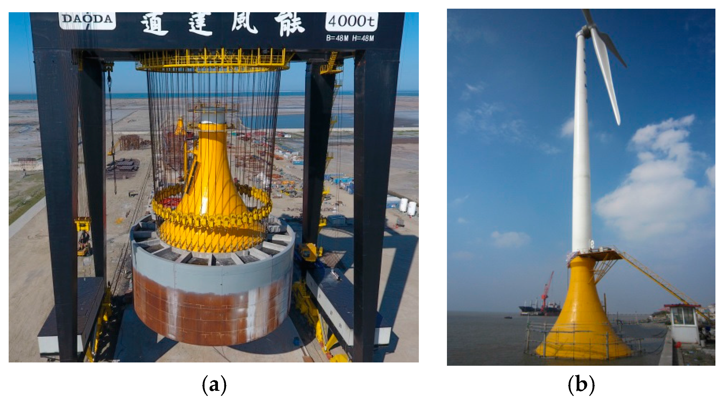
Figure 1 presents the images of the offshore test facility located in Qidong (Jiangsu Province, China).
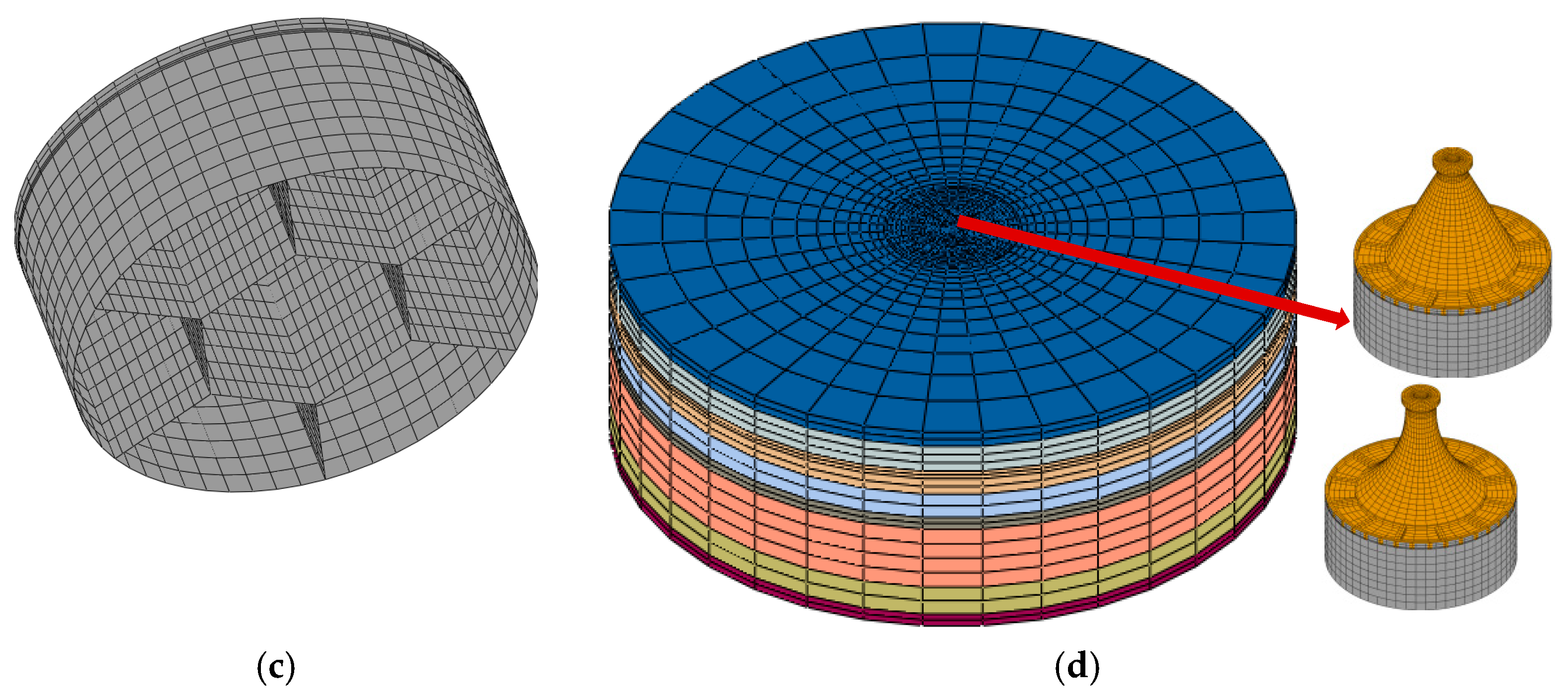
Figure 2c shows the difference between the traditional bucket foundation and the new CBF. The overall structural system mainly consists of the upper transition section (yellow part shown in
Figure 1), a beam-slab system on the top cover, and the steel cylinder with honeycomb rooms, whose bucket is a large cylindrical structure that is opened at the bottom and closed at the top. The cylindrical part is denoted as the bucket skirt, and the upper plate that closes the bucket is denoted as the bucket lid. The entire composite bucket has a clear wall height of 12 m and a diameter of 30 m. At present, two forms of transition sections are considered: arc- and line-type. The offshore wind turbine foundation is subjected to huge horizontal load and bending moment, and in actual designs, it must find a reasonable structural form to effectively transfer loads to the seabed soil through the cooperation of each part.
In this paper, a numerical 3D FEM based on engineering practices in China was set up to investigate the load transfer characteristics, bearing modes, and the contribution of each part of the composite foundation under monotonous and ultimate load conditions. The impact of arc-type curvature was also studied.
2. Finite Element Models of Two Typical Foundations
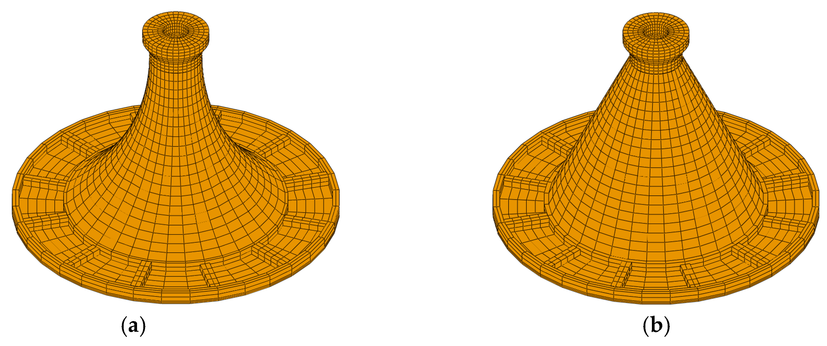
The CBF for offshore wind turbines consists of an upper transition section, a beam-slab structure, and a steel bucket with honeycomb skirt, which includes a concrete transition segment of hollow thin-walled structures, as shown in
Figure 2. According to the upper transition section structure, two different foundations are used in the project: arc-type (
Figure 2a) and line type (
Figure 2b). The CBFs have a clear wall height of 12 m and an outer diameter of 30 m, including a magnified area that is 3 m high on the top. The wall thickness (
T) of hollow thin-walled transfer segment is 0.6 m, the center distances on the top opening (
D1) and bottom (
D2) are 4.4 m and 19.5 m, respectively. The arc transition section has a curvature radius (
R) of 21.7 m, and the entire transition section height
H1 is 19.8 m. The main and secondary beams are arranged in the radial direction; the cross-section heights of the main beam and the secondary beam are 0.9 m and 0.6 m, respectively. The slab on the top cap is a concrete structure with a thickness of 0.3 m. Moreover, the composite bucket has a height (
H2) of 12 m and a diameter (
D) of 30 m. In this model, the ratio between
D2 and
D is 0.65. The overall FEM is shown in
Figure 2.
The CBF system has a complex shape, which makes it difficult to determine the transfer characteristics and bearing mechanism in layered soil. A 3D FEM is established by using ABAQUS, and both the pre-stressed and non-pre-stressed models are considered.
The transition section and beams are made of concrete C50, with a characteristic strength of 50 MPa. The concrete, steel bucket skirt and subdivision plates are assumed to form an ideal elastoplastic model. The Young’s modulus of the concrete is 34.5 GPa and that of steel is 206 GPa. The Poisson’s ratio of steel is 0.3 and that of concrete is 0.17. The two types of pre-stressed transition section consist of the same steel strand and tension control stress of 1320 MPa. The number of pre-stressed channels along the circumference is 48, and each layer is 24 m in thickness along the wall. Each channel has 11 steel strands consisting of seven pre-stressed steel wires; the corresponding Young’s modulus is 2.0 × 10⁵ MPa, and the yield strength is 1860 MPa.
The geological conditions at the present and potential future sites for offshore wind farms in China, which feature silty sands, silty clays, muddy silty clays, etc., are complex. The typical soil used in this paper is from a planned wind farm site located off the coast of Jiangsu Province. Based on the soil test results listed in
Table 1, the height of the soil is 150 m and the diameter is 50 m; the soil is modeled as an elastic-plastic model according to the Mohr-Coulomb failure criterion.
For convenience, the soils are all simulated by a standard element of C3D8R. The contact pair algorithm in ABAQUS is employed to simulate the contact features of the interface between the foundation and soil, and the friction coefficient is 0.35. To estimate the tangential ultimate frictional resistance, Coulomb’s friction law is used. The foundation and soil are tied together, thus no slip will occur when the shear stress on the contact surface is less than the ultimate frictional resistance. The bottom surface of soil is subjected to the constraint of fixed end and the normal constraint is applied to the lateral boundary. Prior to loading, stress balance is eliminated, and the additional deformation due to the gravity of structure is eliminated.
3. Analysis of the Force Transfer Characteristics of Bucket Foundations
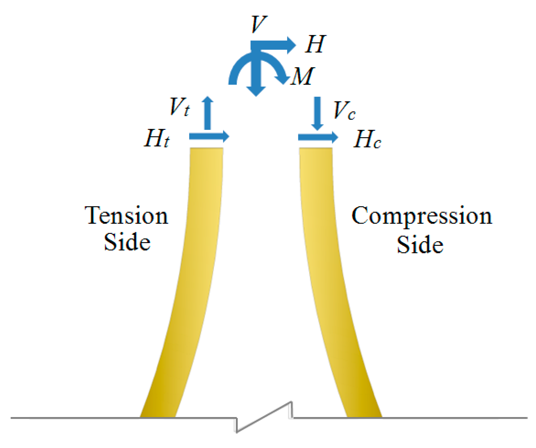
From the mechanical perspective, the main load transfer to the top of transition section is bending moment (
M), horizontal load (
H), and vertical load (
V). The combination of loads is a simplified calculation under various load conditions. A simplified structure is necessary when performing structural analysis and design. Therefore, beam theory is used to calculate the transfer segment during the design. The load conversion diagram of the transition section under external load is shown in
Figure 3.
As shown in
Figure 3, under composite loads, the transfer section is compressed on one side and tensile on the other. The external load is converted to horizontal or vertical force alone or into a combination of both of them on the transfer section. The calculation methods are presented below.
For vertical force only, the maximum normal stress of each cross-section is:
For bending moment only, the maximum normal stress of each cross-section is:
where
ymax represents the outer radius of each cross-section.
The second moment of the transfer segment is given by:
where
d1 is the outer diameter of the section,
d2 is the inner diameter of the section,
t is the thickness of the transition section, and
A is the circular cross-section area.
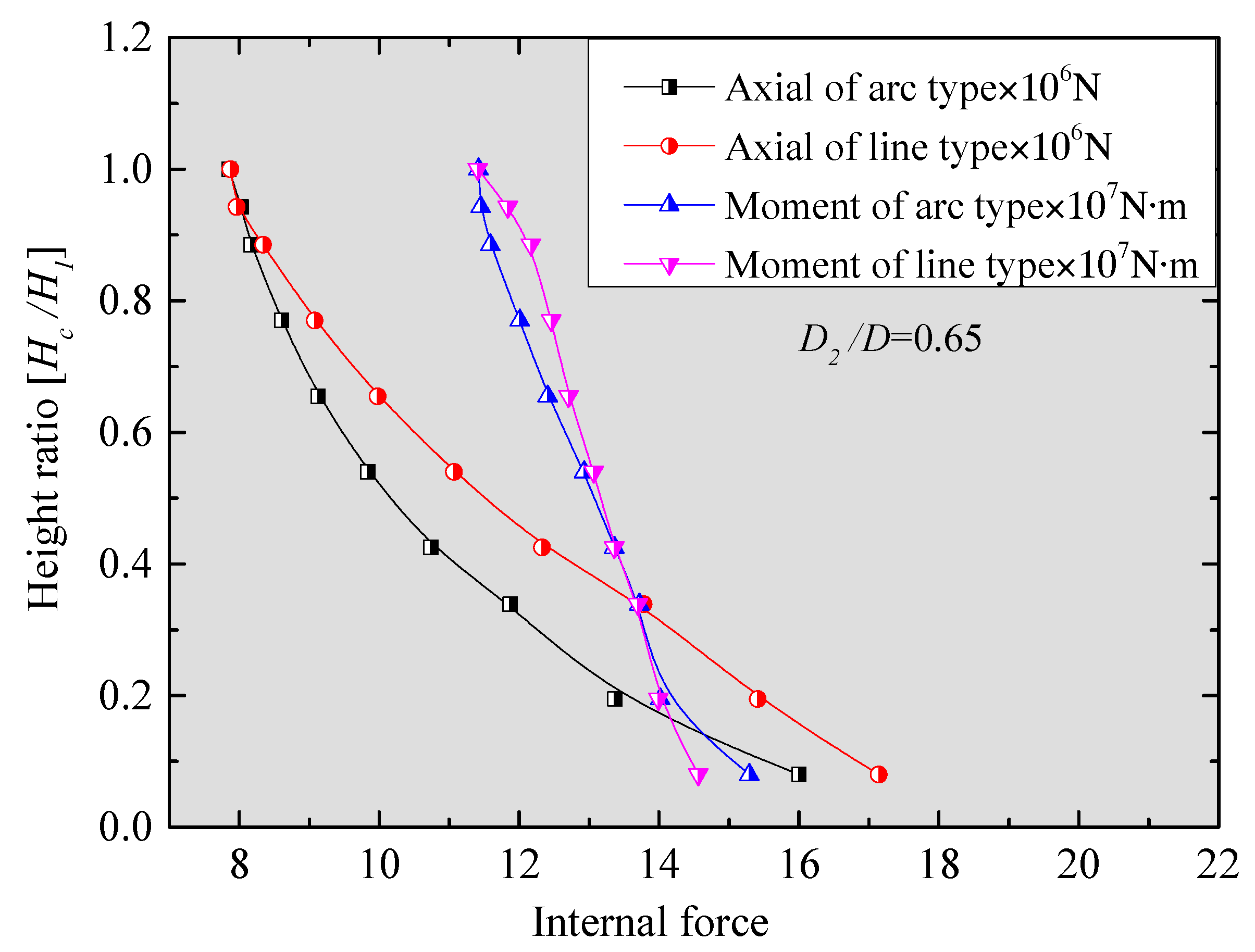
The internal force of each cross-section is respectively calculated, as shown in
Figure 4.
The CBF transition section is located in sea water. For the concrete transfer section, when concrete cracking occurs in the tensile zone, the compressive strength of concrete does not reach the design value, indicating that the structure is already facing the threat of corrosion. Hence, in order to adjust the tension and compression force balance as well as to prevent the occurrence of cracks, the transition section should be designed as a pre-stressed structure. The vertical force on each cross-section of the transition segment is primarily generated by the pre-stressed tendons.
The compressive stress on each cross-section of the transition section resulting from the pre-stressed tendons is given by:
where
Fp is the resultant force produced by the pre-stressed tendons, and
A is the area of each cross-section.
According to the above calculations, the tensile and compressive stress of each cross-section under the combined action of a bending moment and the pre-stressed steel are respectively given by:
where
σC,max is the max stress on compressive side of cross-section, and
σT,max is the max stress on tension side of cross-section.
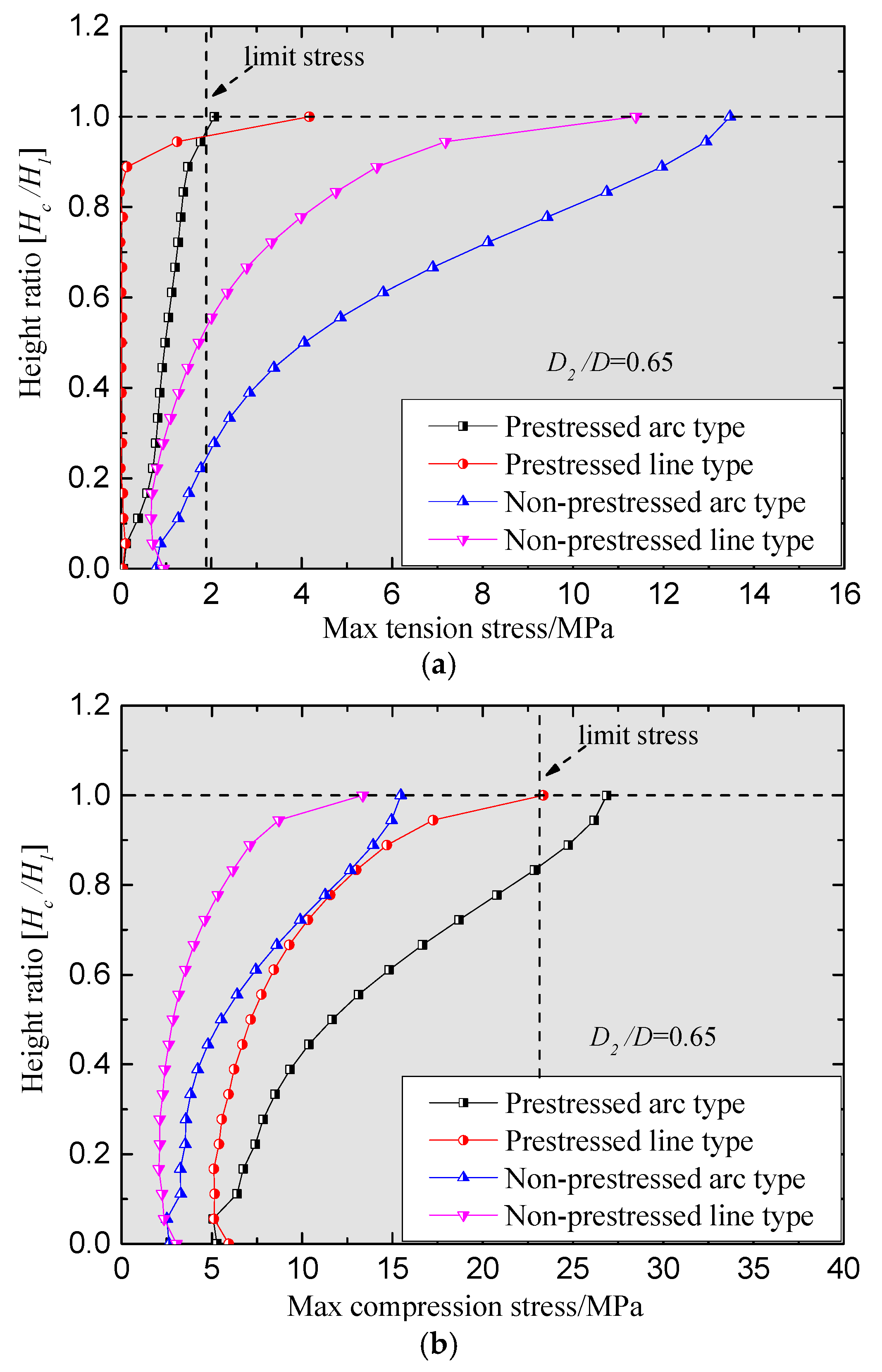
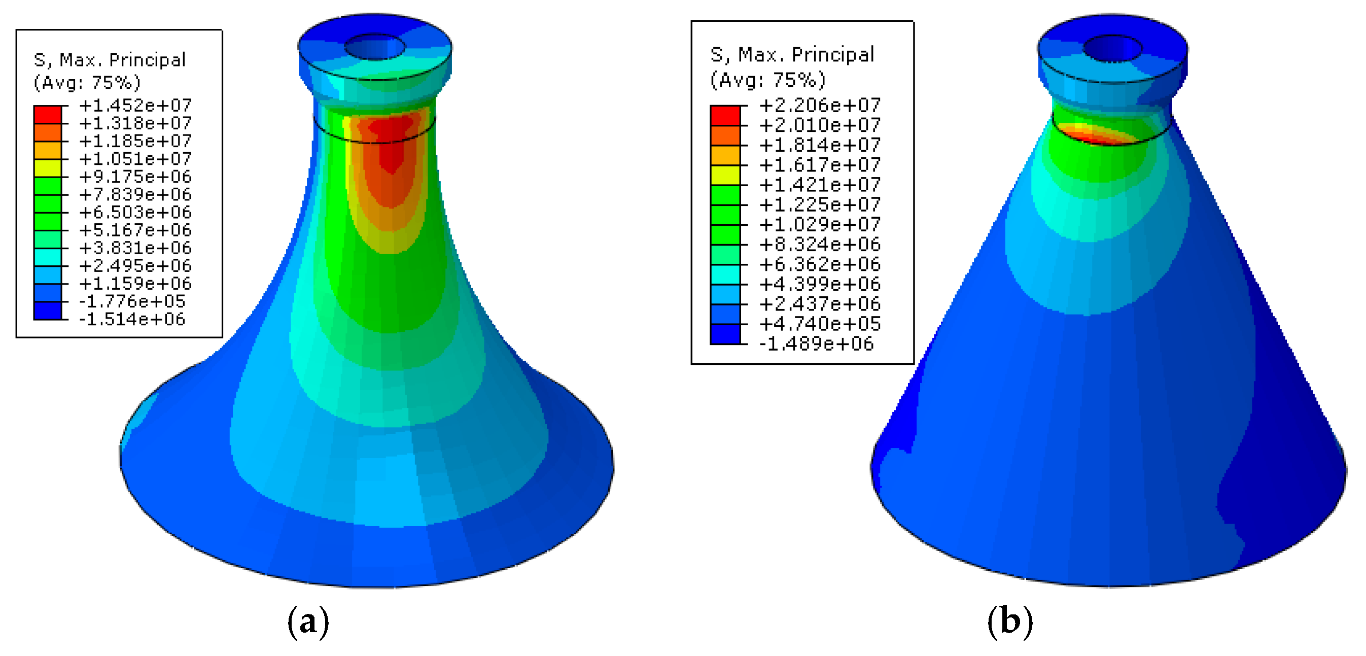
The maximum compressive and tension stress of the two types of CBF under the ultimate load of 50-year return periods are shown in
Figure 5a,b, respectively. As shown in
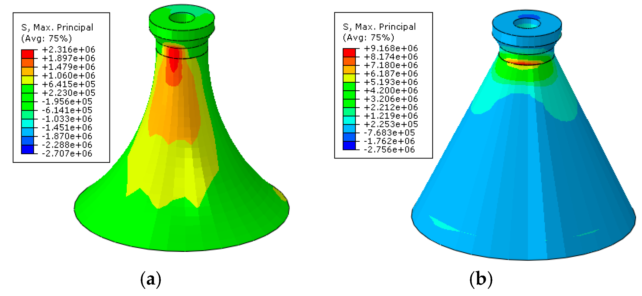
Figure 5a, the line- and arc-type have significantly different force transfer characteristics, showing that the compressive and tensile stresses are greatest at the top of the transfer segment. The tensile stresses of the non-pre-stressed arc and line structures are approximately 14.5 MPa and 13.2 Mpa, respectively, and the compressive stresses are approximately 15.5 MPa and 16.9 MPa, respectively. On the tension side, the maximum stress on each section exceeds the ultimate strength of C50 concrete. Meanwhile, the stress does not reach the limit value on the compression side of the transition section. As shown by the curve of the pre-stressed model, the peak tensile stresses on each section of line-type and arc-type are less than the limit value of 1.89 MPa. Most cross-section stresses of line-type are even close to zero. Meanwhile, the compression stresses on each section of the pre-stressed model increases, but they are always lower than the limit value. For the line-type, the compression stresses on each section of arc-type are less than the limit value of 23.1 MPa.
For the arc-type, the compression stress increase ratio is 49%, and the average tension stress reduction ratio is 78%. For the line-type, the corresponding values are 55% and 93%, respectively.
The tension and compression stress distribution results calculated by FEM are shown in
Figure 6 and
Figure 7. Both regulations between the pre-stressed line and arc-type or the non-pre-stressed model can be clearly seen, which are essentially consistent with the calculation results shown in
Figure 5. The pre-stressed line-type has better load-bearing performance than the arc one; the former can also maintain a lower stress level in most cross-sections throughout the entire transitional segment, except at the top. Therefore, the line structure has better capability to resist cracks. Owing to the special structural form, the arc structure can help gradually diffuse and distribute stress along the height and circumferential directions.
In contrast, both transitional segments can gradually transfer the huge bending moment load downwards at the upper structure of the turbine with the pre-stressed tendons until the load becomes relatively smaller, and further changes into controllable tensile and compressive stresses. However, the section area of line-type is larger than that of arc-type at the same height, representing one disadvantage of wave loading diffraction theory.
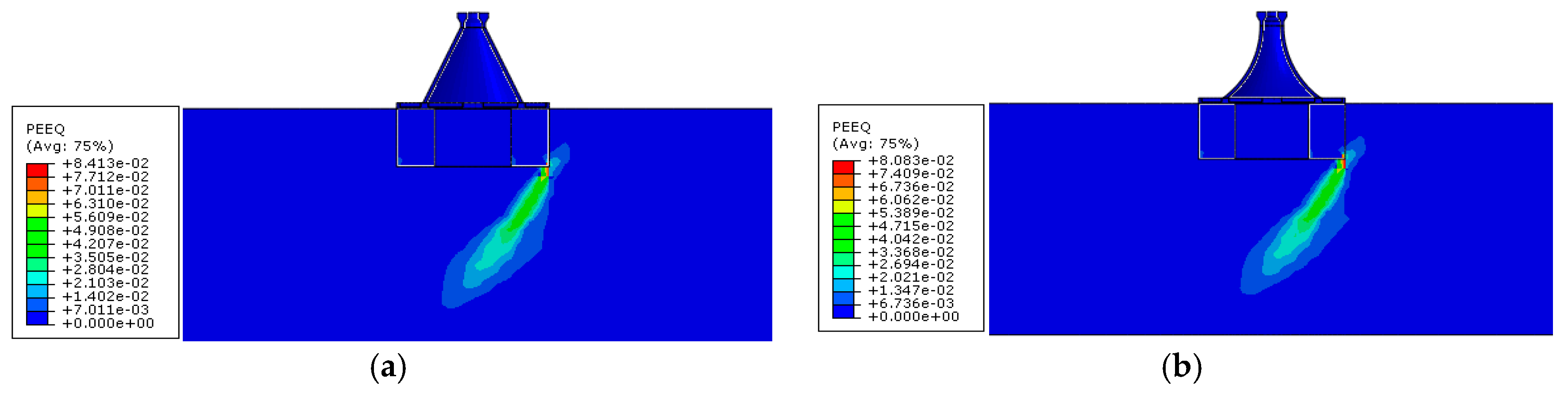
Figure 8 shows the computation results of equivalent plastic strain under ultimate load condition. When the equivalent plastic strain is larger than 0, the soil will yield.
Figure 9 shows the displacement distribution field of two kinds of foundation under ultimate load condition, illustrating that the two failure modes are essentially similar, i.e., the failure region first occurs in front of the bucket wall and then extends along the loading direction to the bottom of the bucket. The failure modes include wedge-shaped failure and sliding-shear failure. In addition, the plastic strain area of line-type is slightly larger than that of arc-type; their maximum values are 8.41 × 10
−2 and 8.08 × 10
−2, respectively. As can be seen from
Figure 9, under combined loading, as the load increases, the deformations of arc- and line-type are also the same, which further develop to a rotational failure. The deformation of line-type is relatively larger than that of arc-type; their maximum values are 62.82 mm and 69.92 mm, respectively. The line foundation transfers more loads to the soil, and a wider soil area around the foundation is involved in load bearing. According to the design provisions of wind turbine foundation, the CBF of 3 MW has a limit tilt rate of 3‰, and a settlement value of 100 mm. In summary, the line composite bucket shows better performance in terms of deformation control and transmission mechanism.
4. Analysis of the Load-Bearing Mode
The CBF bucket has a diameter of 30 m, and the insertion depth of bucket wall is about 12 m; these are significantly different from those of traditional bucket foundations. The resistance of a bucket foundation under monotonous and combined load conditions mainly includes the front soil pressures inside and outside the bucket wall, the back soil pressures inside and outside the bucket wall, and the earth pressures on the top cover and separating plate. Therefore, the relationship between the upper structure form and the bearing mode requires further investigation. The height to diameter ratio of the bucket foundation is 0.4, and the internal space of the bucket is divided into seven rooms by separating plates. According to [
2], the separating plate is designed mainly for controlling the suction process; they can also provide safety reserves for the bearing capacity of CBF. Therefore, the effect of partition plates is not considered in the current calculation.
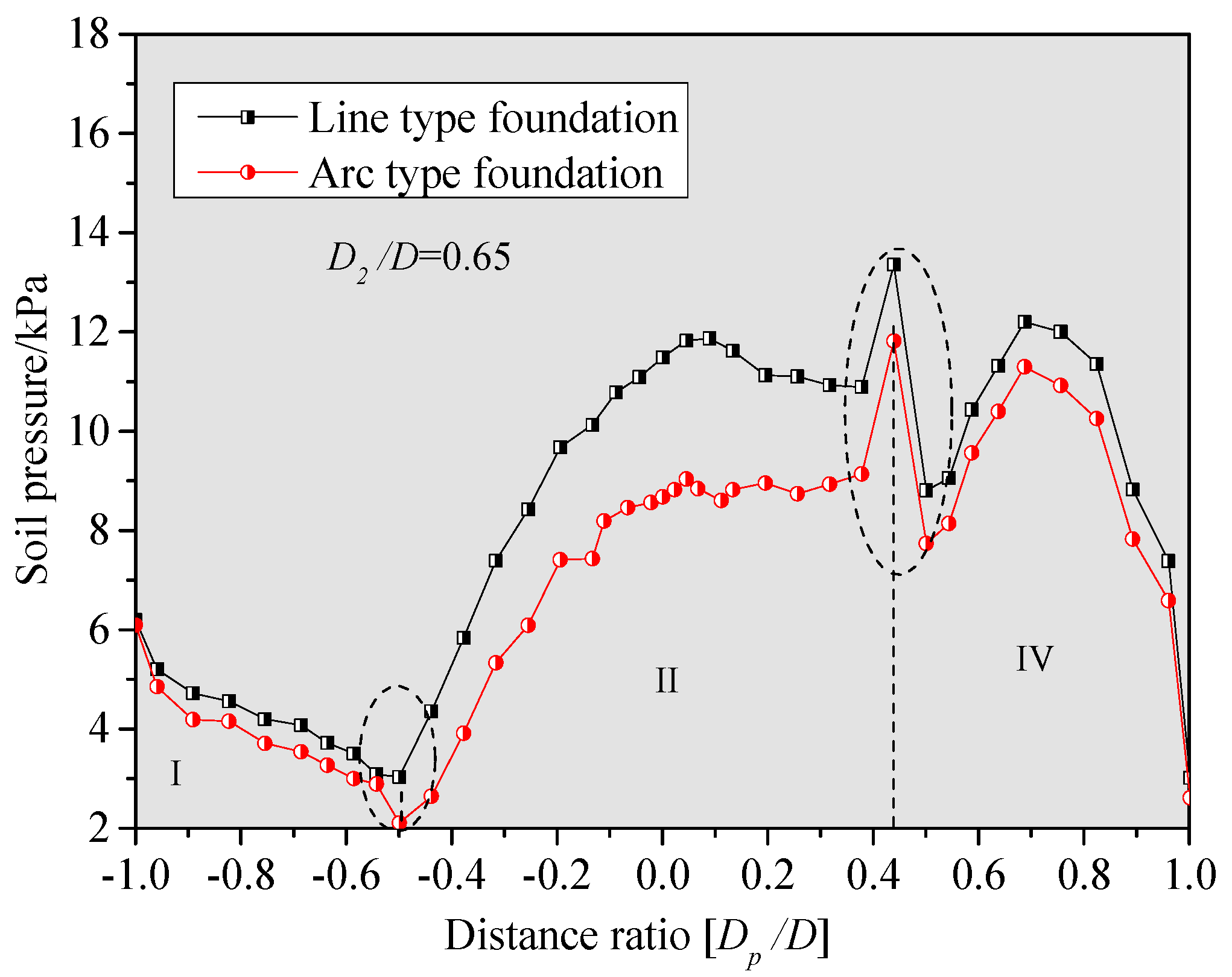
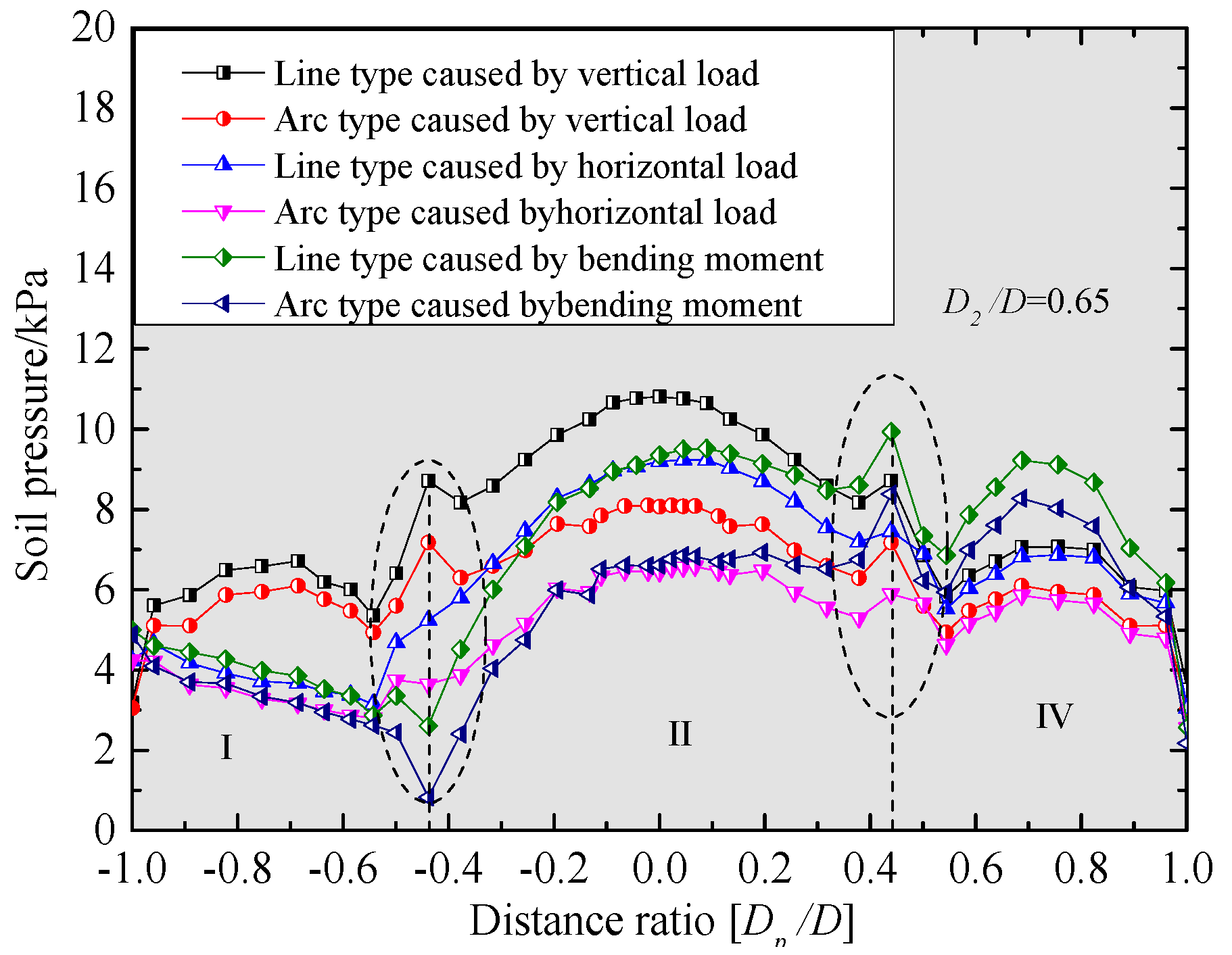
Figure 10 shows all the distributions of the earth pressure on the top cover of arc- and line-type foundations under horizontal, vertical, and bending loadings.
Figure 11 shows the soil pressure inside and outside the front bucket wall, whereas
Figure 11 presents the back soil pressure inside and outside the bucket wall under monotonic loads along three directions
As can be seen from
Figure 10, the earth pressure on two sides of the top cover center presents a symmetrical distribution under vertical load. The maximum soil pressure is relatively large near the center of the top lid, and two increasing points can be found at the location where the distance ratio is close to 0.4. This can be mainly attributed to the fact that the upper structural load is transferred to the inner-ring beam on the top cover through the transition segment, and that the ring beam diameter is approximately 19 m. Therefore, a significant amount of load is transferred to the annular region (I and III) between the inner- and outer-ring beam, and then distributed in the surroundings.
Figure 9 also shows that the line-type foundation can bear more earth pressure than the arc one. The soil pressure distribution due to the bending moment and horizontal loads are roughly the same as that due to the vertical load. In the calculation results, the overall deformation of the foundation under the bending moment is a combined deformation of rotation and movement. Therefore, the calculation results in region I are reduced, and the soil pressure in region III significantly increase simultaneously. Overall, the soil pressure on the top lid of line-type foundation is greater than that of arc-type under monotonic load.
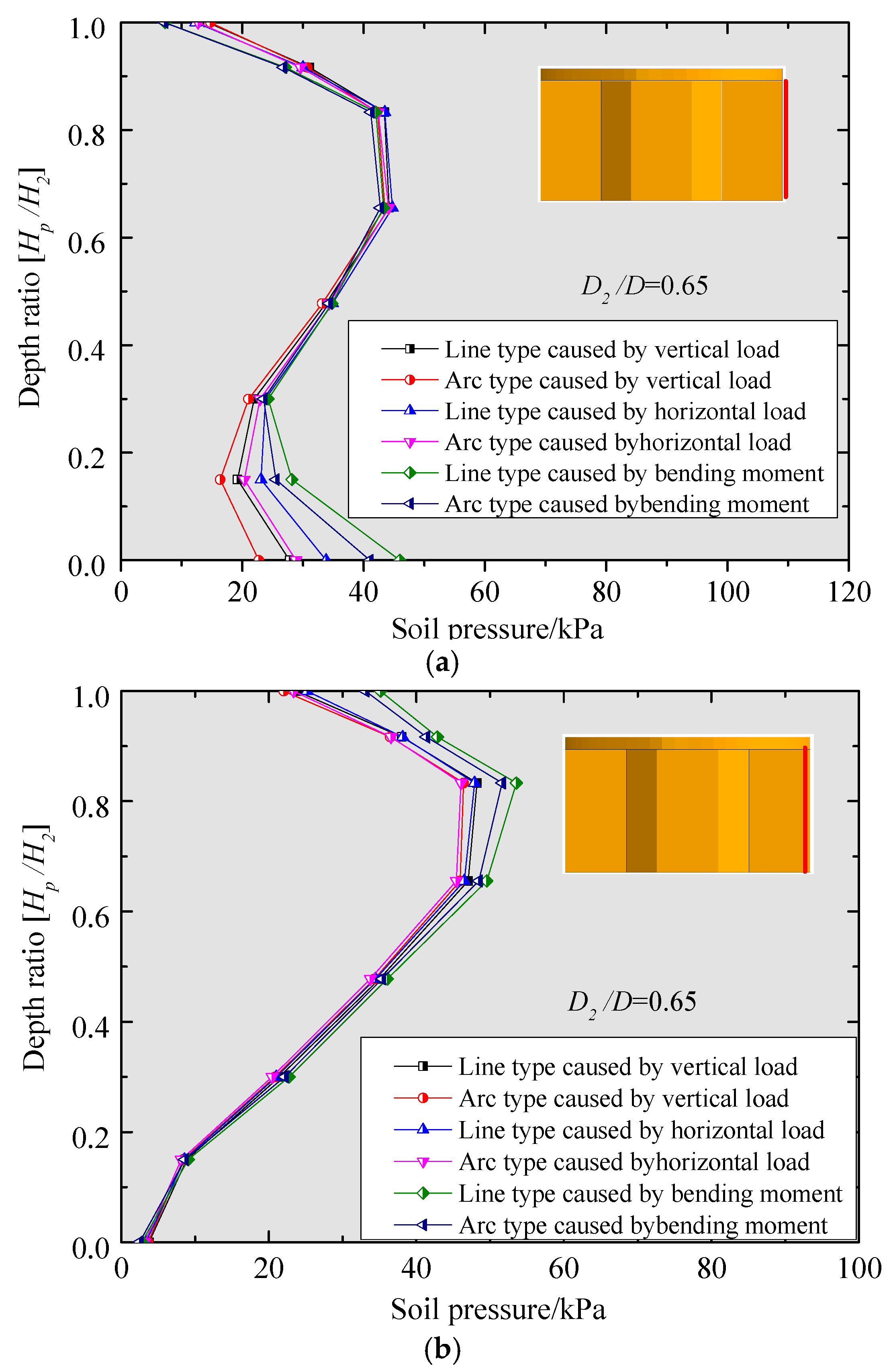
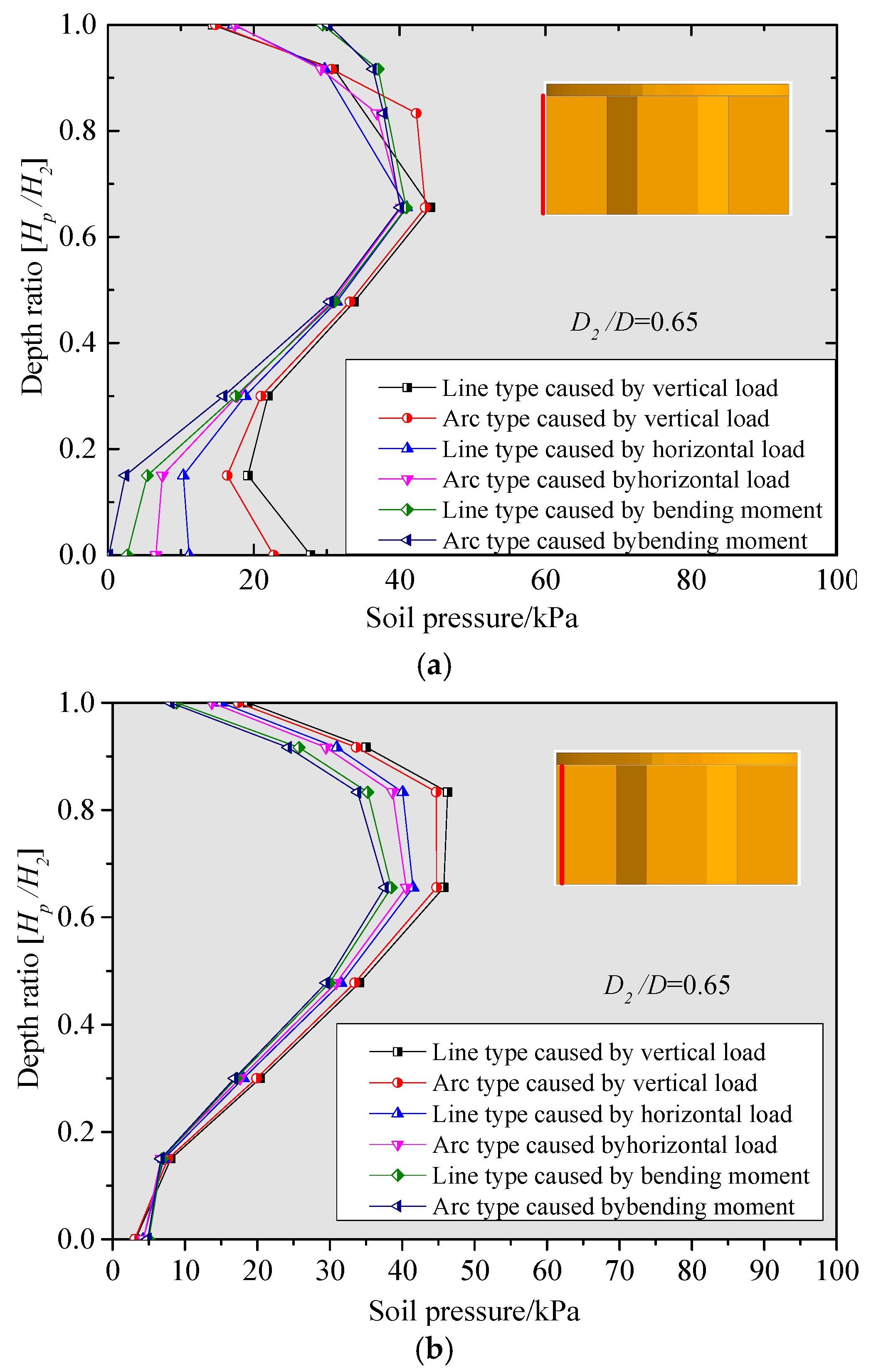
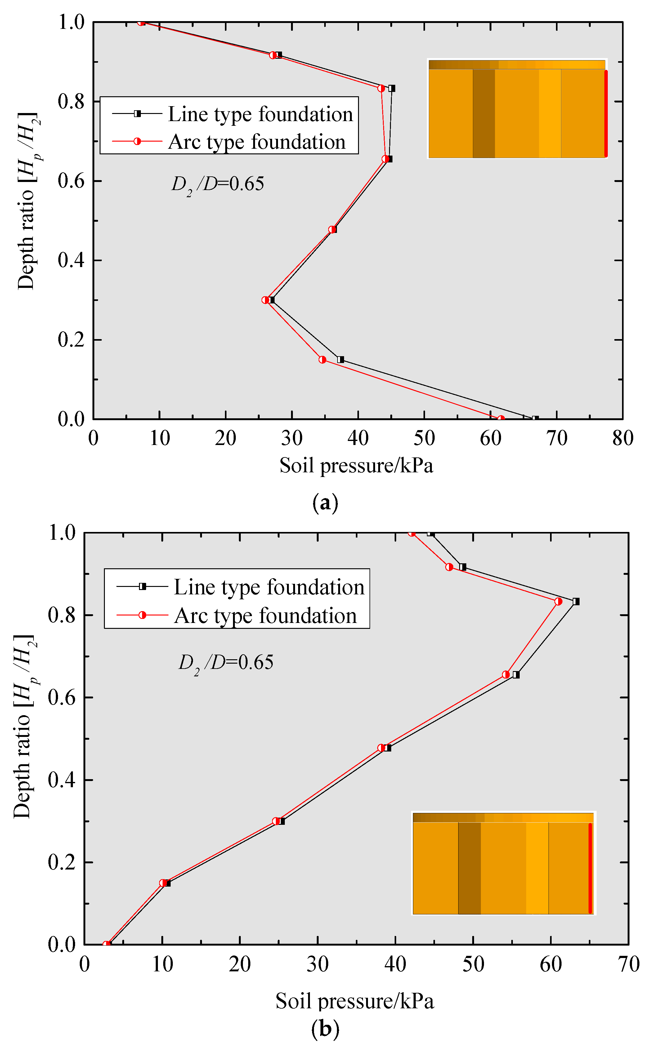
Figure 11 shows the soil pressures inside and outside the front bucket wall under the monotonic vertical, horizontal, and bending moment loads. As can be seen from
Figure 11a, the external earth pressure along the front bucket wall of the two types of foundation shows the same S-shaped distribution under monotonic load. The maximum value is on the skirt top.
Figure 11b illustrates the external earth pressure along front bucket wall, showing that it increases gradually from the skirt top and decreases close to bottom at a depth ratio of 0.7.
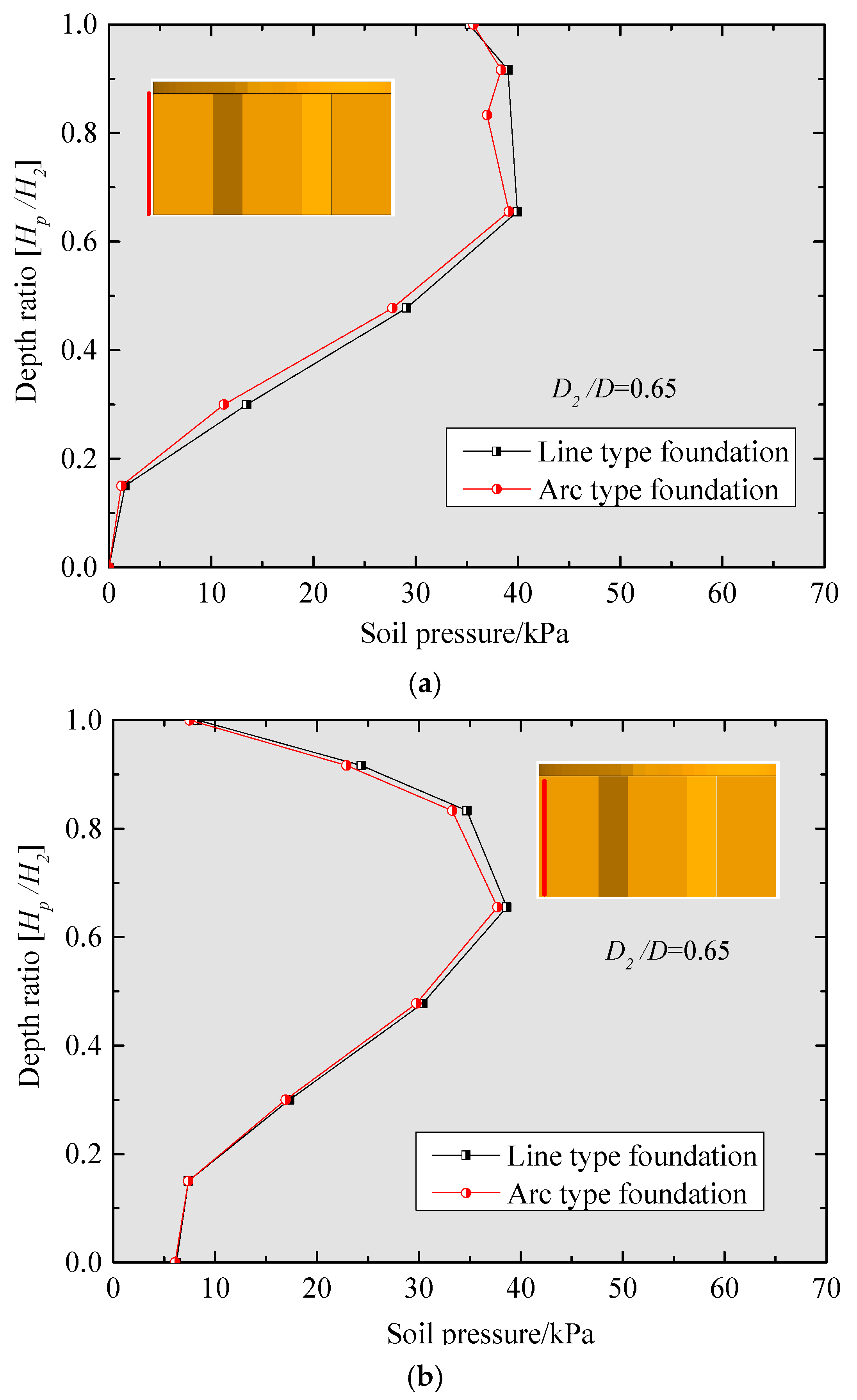
Figure 12 presents the soil pressure distribution inside and outside the back bucket wall. It can be seen that the regular soil pressure patterns on the back skirts are the same as those in the front bucket wall. This is because the inner and outer sides of the bucket are divided into a passive (in the direction of the load) and active region (in the opposite direction). In any case, the soil pressure of line-type is greater than that of arc-type. Therefore, the line-type foundation is capable of transferring more loads in the vertical, horizontal, and bending moment directions through its bucket wall.
Figure 13,
Figure 14 and
Figure 15 show the soil pressure distributions on the top lid and bucket wall of different foundation types under the ultimate load of a 50-year return period. As shown in
Figure 13, the soil pressure distributions in regions I, II, and III undergo changes. Most of the soil pressure is located on the top lid along the direction of the load. The soil pressure is almost close to zero at the position where the distance ratio is 0.5. This finding indicates that the soil inside the bucket lid is about to be disengaged with the top cover. The calculation results show that, under the ultimate load, the overall deformation of the two foundations is a combination of rotation and movement, as well as the bending moment. Moreover, the soil pressure on the top lid of the line-type foundation is greater than that of arc-type.
Meanwhile,
Figure 14 reveals the soil pressures inside and outside the front bucket wall. As shown in
Figure 14a, the external earth pressures along the front bucket wall of the two types of foundation types have an S-shaped distribution under the monotonic load. The soil pressures inside and outside the front bucket wall of line-type foundation are close to those of the arc-type. Hence, the distribution is consistent.
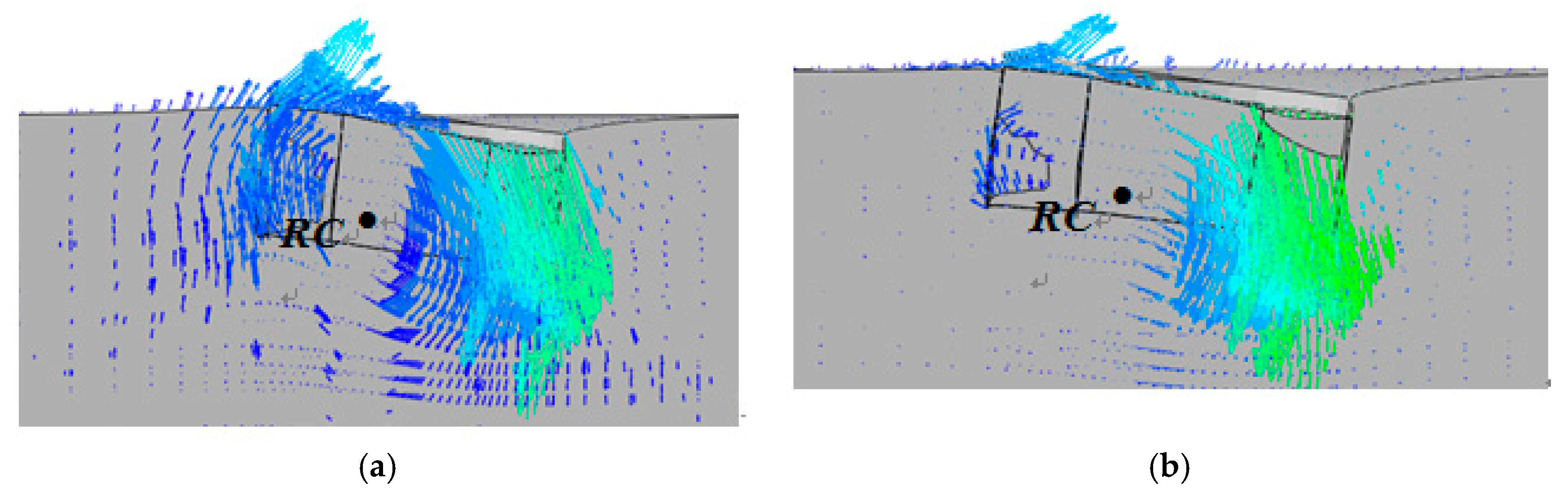
Figure 16 present the deformation vectors for the two types of foundation based on the FEA calculation result. Taking the bending moment load condition as an example, we can see that the deformations of both foundations are mainly rotational under bending moment load, and that the location of rotation center changes continually in the deformation process.
The location of rotation center is identified at the point that is located near and on the left side of the central axis of bucket foundation in the opposite direction of the load. The depth ratio of rotation center is approximately 0.65 times of that of the bucket wall height, and this can be set as shown in
Figure 17.
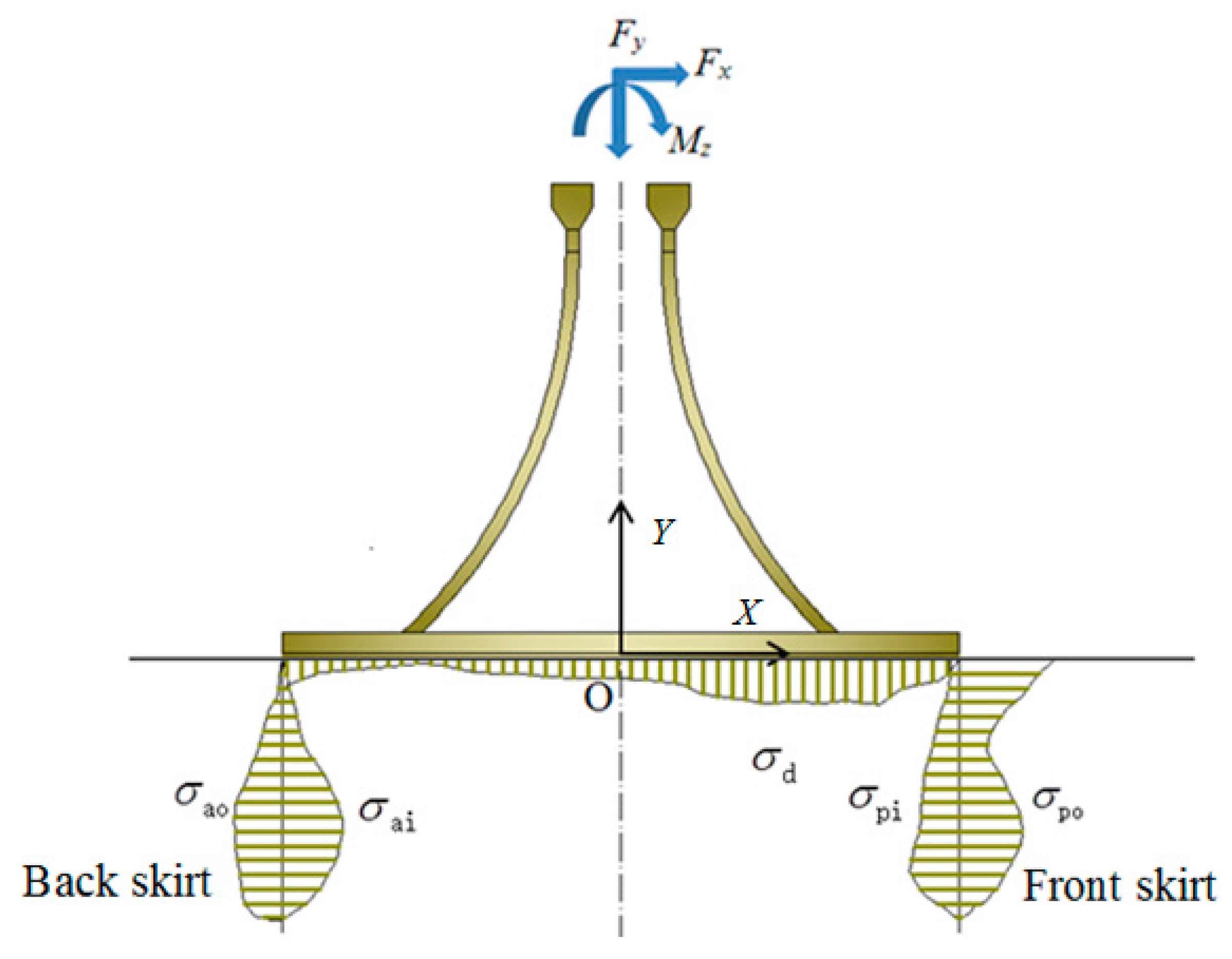
To further investigate the contribution ratio of each part of the bucket foundation and to identify the bearing mode of two types of CBF, the distribution characteristics of soil pressure on the top lid and on the front and back skirts are shown in
Figure 17. It can be seen that larger soil pressures can be found on both sides of the front and back bucket walls. Moreover, the soil pressures on the skirts are in opposite directions; therefore, the soil pressure on bucket wall is extremely small after the counteraction. The structure is in a limit equilibrium state under the ultimate load of a 50-year return period. The resultant forces on the top cover and the bucket wall are calculated according to Equations (7)–(9), with results listed in
Table 2.
The resultant forces on the front bucket wall, back bucket wall, and bucket top lid are respectively given by the following equations:
where
H represents the height of bucket wall;
R represents the diameter of bucket;
σpo represents the soil pressure outside the front skirt;
σpi represents the soil pressure inside the front skirt;
σao represents the soil pressure outside the back skirt;
σai represents the soil pressure inside the back skirt; and
σd represents the soil pressure on the bucket top cover.
Ignoring the influence of the honeycomb partition plate, the bearing ratios of top cover to the front and back skirts under monotonic and ultimate load are listed in
Table 3. It can be seen that under vertical and horizontal load conditions, the bearing proportion of the top cover of line-type is approximately 52%, whereas that of arc-type is approximately 49%. For the action of bending moment, the proportions are almost 56.4% and 54.7%, and they can reach 65.8% and 65.2%, respectively, especially under the condition of the ultimate load of a 50-year return period. Therefore, the top cover of CBF is the main part of load bearing with the bucket wall as its auxiliary. This means that the bearing mode of CBF is a “top-cover bearing”. For the top lid bearing foundation, the above results are in accordance with the conclusion obtained in
Section 2 and
Section 3, indicating that the line-type foundation conforms better to the design concept of CBF for offshore wind turbines in terms of the load-bearing mode of bucket top cover.
5. Analysis of the Curvatures of Different Arc Type Foundations
From the above analysis, we can see that the upper structural type of transition section significantly affects the distribution of soil pressure on the top lid but not on the bucket skirt. The bearing capacity of two foundation types tends to converge substantially on the bucket skirt under the combined and monotonous load conditions, without a significant difference. For an arc transition section, the structure type is determined by the curvature radius, which is related to the ratio between D2 and D. Hence, the arc transition section with a different curvature radius can affect the force transfer and bearing mode.
In this section, FEM is established to determine the impact of curvature radius on the top cover bearing mode of the arc-type bucket foundation.
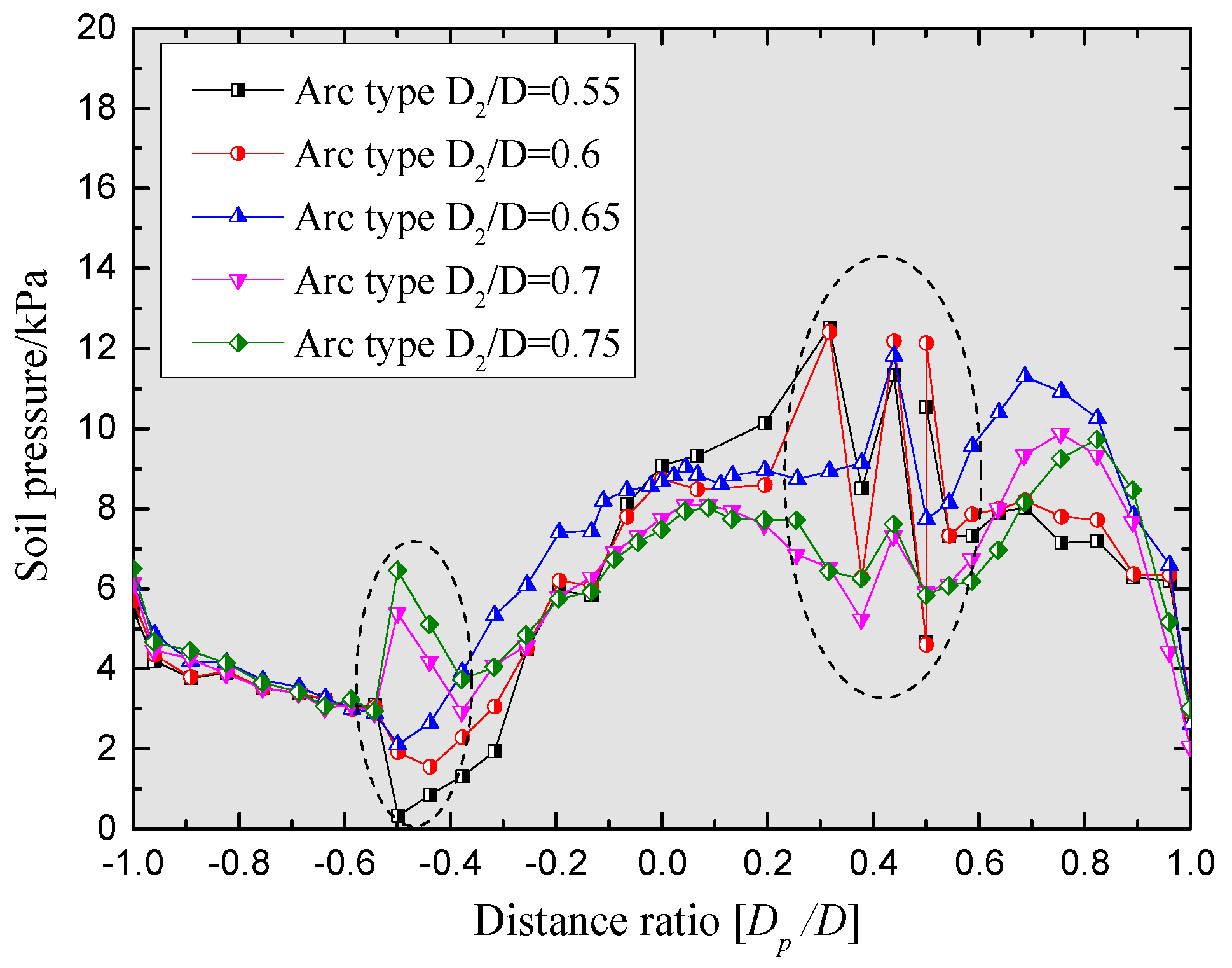
Figure 18 presents the distribution of soil pressure on the bucket top lid of the arc-type foundation with different curvature radii.
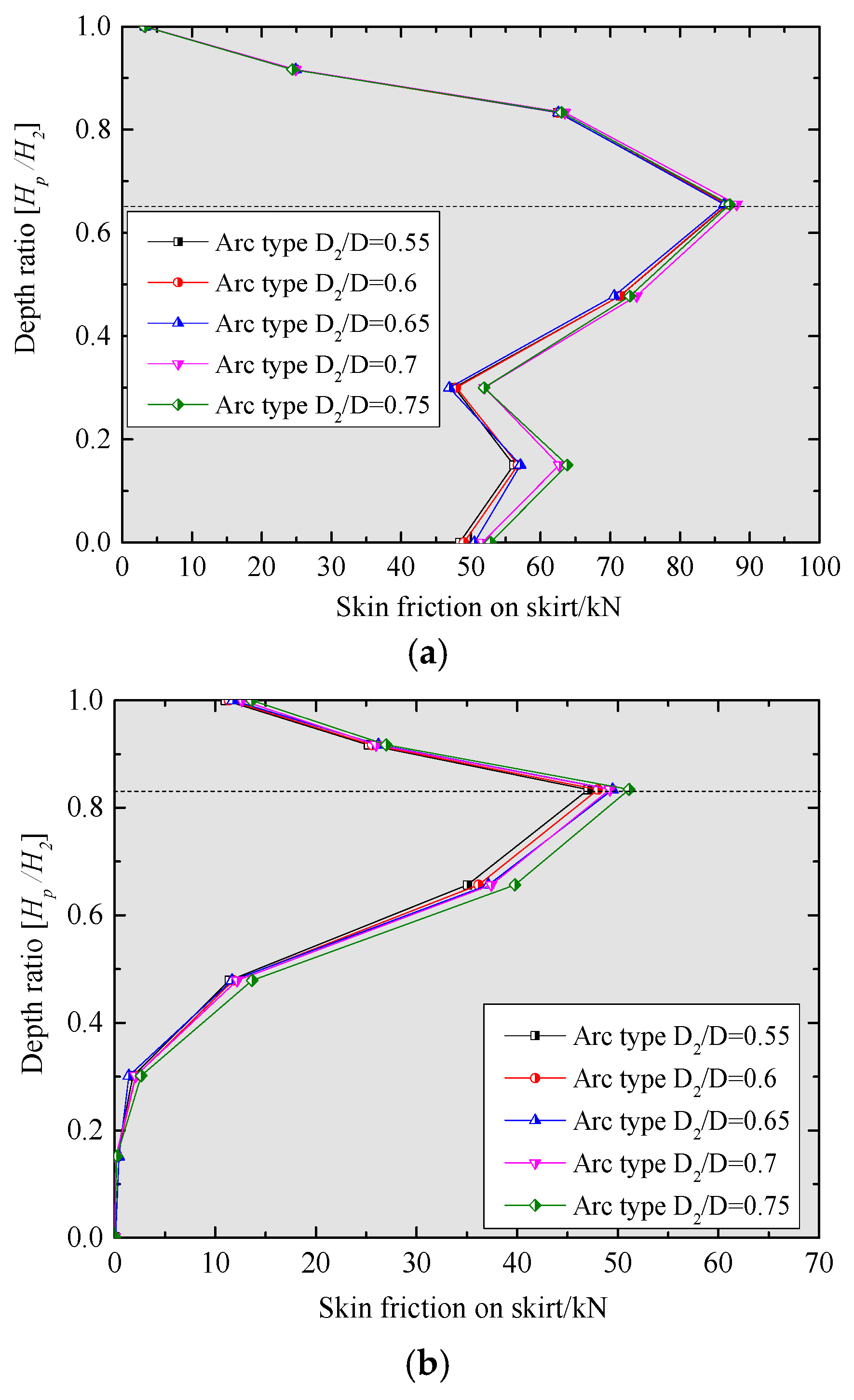
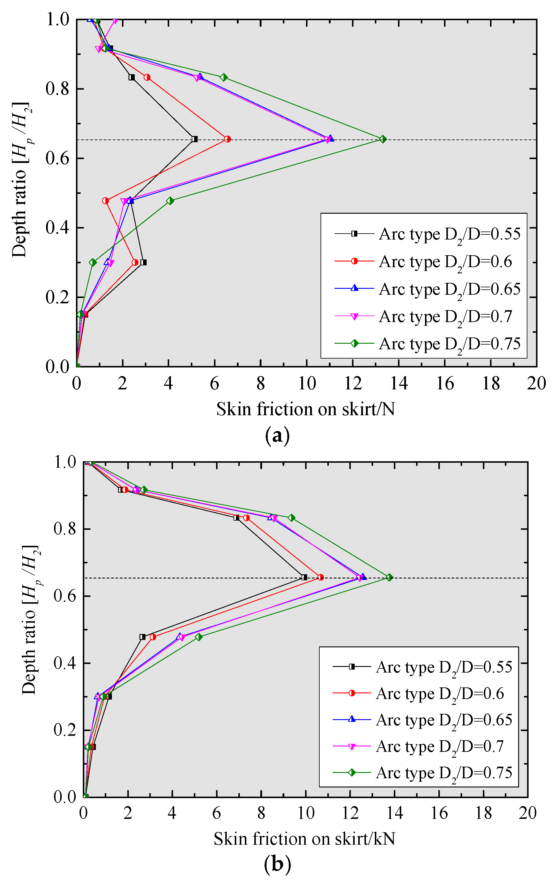
Figure 19 present the skin friction distributions outside and inside the back bucket wall.
Figure 20 presents the skin friction distributions on the front bucket walls of different arc foundations.
As shown in
Figure 18, the curvature of arc-type transition section has certain effects on the top cover load-bearing mode. The earth pressure on the top lid increases with the increase of diameter ratio, and decreases when the ratio is larger than 0.65. This finding means that the top lid bears more loads when
D2/
D is 0.65. Meanwhile, we can see from
Figure 19 that the regular pattern of skin friction on the back skirt is the same as those on the front bucket wall; moreover, the skin friction increases gradually from skirt top to a depth ratio of 0.65, and decreases from this depth ratio to the skirt bottom. The maximum value of skin friction is also obtained when
D2/
D is 0.75.
Figure 20 reveals that the skin friction is larger outside the bucket wall than that inside the bucket wall. For the arc-type, the change of skin friction on the back bucket wall is not obvious with the enlarged diameter ratio
D2/
D.
The above results can be explained as follows. The force transfer function of top cover is gradually attenuated when the margin of transition section extended to that of the bucket wall; meanwhile, the upper load is directly transferred to the bucket wall margin through the transition segment. These findings indicate that the maximum utilization ratio of the bucket top lid is reached when D2/D is 0.7. When D2/D is less than 0.7, the transition segment is not extended to the edge of the bucket; instead, the load is transferred to the top cover with the transition section, and further to the bucket wall margin.
Compared with the above results shown in
Section 4, the structural type of the upper transition structure must be closely associated with the force transfer and load-bearing mode of CBF. Moreover, the line-type structure outperforms the arc-type at the same ratio; hence, the effect of
D2/
D can be considered negligible. Consequently, optimizing the structural type is critical to the foundation design. The arc-type could preferably convert the load and control cracking through an arch force transfer pathway. However, according to the design concept of the bucket foundation with the top cover force bearing, the line-type transition section must have a thicker top cover to transfer the load to the subgrade.


