1. Introduction
With the increasing penetration of wind power integrated into the power system [
1,
2,
3,
4], power system operators (PSOs) have enforced more stringent connection requirements on the doubly-fed induction generator (DFIG) based wind turbines [
5]. One of these requirements is the low voltage ride-through (LVRT) capability of wind turbines, i.e., the ability of the power plant to remain connected to the grid during voltage sags [
6,
7].
Several research has been carried out to improve the LVRT capacity of DFIG. One common LVRT solution is to install a crowbar circuit across the rotor terminals to damp the over-current in the rotor circuit in order to protect the rotor-side converter (RSC) [
8]. However, it is already recognized that the decoupled control of active and reactive power of the DFIG is temporarily unavailable during the crowbar protection. The DFIG actually works as a conventional induction generator absorbing a large amount of reactive power from the grid which further deteriorates the terminal voltage during the faults [
9,
10]. Therefore, the conservative crowbar protection should be the last choice to limit rotor currents [
11,
12].
In order to cure the drawbacks of the crowbar protection, some control strategies on the RSC and the grid-side converter (GSC) [
13] have been adopted to protect the converters of DFIG. Typically, the control strategy proposed in [
14] was used to accelerate the rotor to convert the excessive electric energy that could not be sent to the grid to kinetic energy. Thus, the surge of the rotor current as well as the DC-link voltage could be reduced. Nevertheless, this approach is limited due to the maximum allowable rotor speed, especially for the generator operating near the rated speed.
Many other advanced hardware aided methods, such as the series GSC [
15,
16], additional resistance circuits [
17], dynamic voltage restorer (DVR) [
18], energy storage system (ESS) [
19,
20], and electric vehicles [
21,
22], have been developed to tackle the LVRT operation. Among these hardware modification solutions, ESS is the most promising method. This is because ESS can help not only realize the uninterrupted operation in fault condition, but also smoothen the power output in the normal operation without using extra power electronic devices [
23].
Another stringent requirement for wind turbines is the reactive power support by DFIG during the grid fault. In [
24], the reactive power capability of DFIG under the steady state condition is investigated. A similar study has been reported in [
25]. The GSC is reconfigured as a reactive power source during grid faults which has been proposed in [
9] and [
11]. However, the reactive power capability of disabled RSC has not been effectively used in these research. In [
8], RSC is put in parallel with the GSC to inject the reactive power into the grid during grid faults. However, the reactive power capability is strictly limited, especially when the voltage drops to a low value. In [
26], a coordinated voltage control scheme is present by using the RSC in collaboration with an on-load tap changer. However, it does not consider the GSC contribution. A coordinated reactive power control of the RSC and GSC is present in [
27]. However, it only considers shallow voltage sags with the minimum remnant voltage of 0.6 p.u.. Another coordinated control of RSC and GSC is suggested in [
13], where the GSC contributes to the reactive power control together with the RSC during large disturbances. However, the reactive power of GSC and RSC is limited since most of them are used to transfer the active power to the grid during grid faults.
In this paper, by installing ESS into the DFIG, a novel coordinated control strategy of LVRT capability and reactive power support capability adapted to different depth of voltage sags for DFIG-ESS is proposed to improve the dynamic performance of the DFIG-ESS system during the grid fault. The key point to realize the LVRT is to handle the excessive energy between the captured wind power and the power injected to the grid by the DFIG that cannot be transmitted into the grid during the transient process. Thus, the ESS connected to the DC-link capacitor of the DFIG is controlled to regulate the DC-link voltage during normal and fault operations. This is equivalent to absorb or compensate the unbalanced power. When the supply voltage suffers a low-level drop, RSC is used to control the maximum power production of the stator while the GSC operates to provide the reactive power before participating into the voltage support. As the supply voltage continues to drop, the rotor speed is increased by controlling the RSC to realize the LVRT capability, and helps the GSC further enhance the reactive power support capability. In the meanwhile, the whole capacity of GSC is dedicated to inject the reactive power into the grid. Moreover, an auxiliary transient pitch angle controller is used to protect the over speed of the generator. Both RSC and GSC act as reactive power sources to further enhance the voltage support capability when the supply voltage suffers a serious voltage sag.
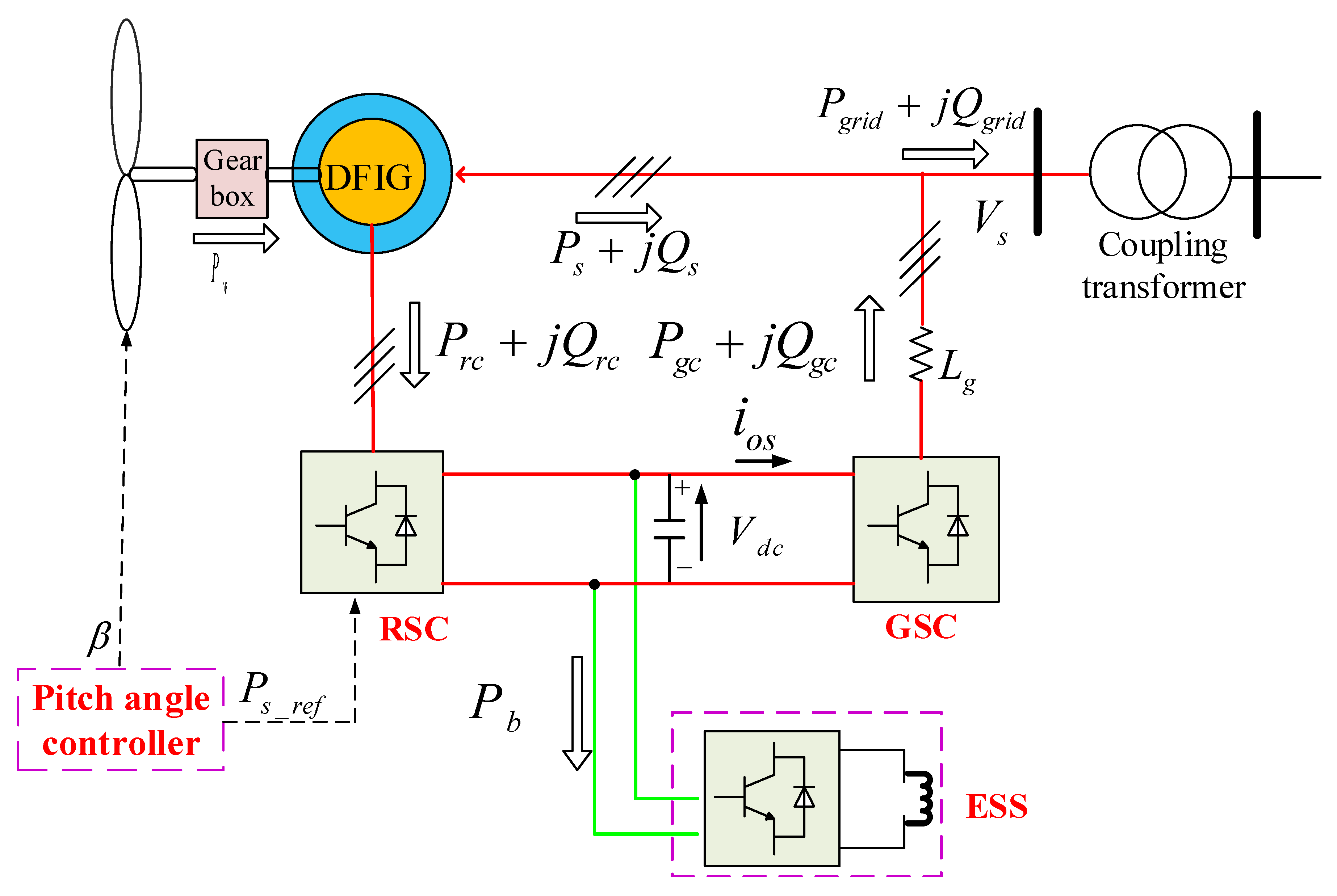
2. Topology of DFIG Incorporated with ESS
The structure of a wind power generator integrated with the ESS is shown in
Figure 1. In conventional configurations, the ESS and the switches connected to the DC-link are absent. The RSC is used to keep the maximum available wind power production and regulate the stator voltage, while the GSC is responsible for regulating the DC-link voltage.
If the stator and rotor copper losses are neglected, the amount and direction of the power flow through the rotor circuit can be approximately expressed as:
where
,
, and
represent the captured wind power, rotor power, and stator power, respectively. Normally, the power flow flocking into the rotor circuit (
) equals 20–30% of the captured wind power (
) during the normal operation at the super-synchronous operation. When the power grid is subject to a short-circuit fault, the transmitting capability of the active power
is extremely restricted due to the decline of the supply voltage. Consequently, it can be seen from (
1) that the large transient wind power flows into the DC-link capacitor through the rotor circuit due to the low response of the generator and wind turbine, especially when the DFIG suffers a serious voltage drop.
According to the reference direction of different power shown in
Figure 1, the instantaneous dynamic response of the DC-link capacitor without ESS can be described as:
where
is the instantaneous input power of the GSC.
and
are the d-axis components of the grid’s voltage and current, respectively.
For the traditional DFIG, the main task of GSC is to maintain the DC-link voltage and provide a path for the rotor power to/from the grid. Hence, the DC-link capacitor can be protected and the adequate voltage on the rotor can also be provided. However, it is difficult to realize that
in (
2) equals zero when
drops to a low value [
28]. This is because the rotor power is large and the instantaneous power
is small and determined by the current limitation of the converter semiconductor
. Therefore, the excessive power
cannot be transmitted to the grid.
It is noted that the DFIG dynamics are exasperated due to the excessive power that cannot be transmitted into the grid during the grid fault. The rotor control might be affected by the DC-link voltage fluctuation when the DFIG is running back to its normal operation [
28]. Therefore, from the energy balance point of view, the key point of suppressing the over-current in the rotor and stator circuits as well as over-voltage in the DC-link is to reduce the power surplus between the captured wind power and the power injected into the grid provided by the DFIG [
14].
By adding an ESS and its converter to the DC-link, Equation (
2) can be re-expressed as:
where
is the power absorbed by the ESS.
By tuning appropriate control parameters of ESS, the left side of Equation (
3) is zero, which means the DC-link voltage can be maintained as a constant value. Equation (
3) can be represented as:
where
and
represent the captured wind power and the active power injected to the grid by the DFIG, respectively.
It can be seen from Equations (
3) and (
4) that the ESS can regulate the DC-link voltage by absorbing or compensating the power from/to the rotor circuit during normal or fault operations. Therefore, there is little risk of over-voltage in the DC-link capacitor, even if the GSC is controlled to transfer zero active power to the grid. In addition, the difference between the absorbed power
and
is essentially equal to those between
and
. Consequently, the excessive power flocking into the DFIG can be handled by the ESS, which is actually equivalent to regulate the transient DC-link voltage during grid faults. Furthermore, the oscillation of the current in the rotor and stator can be reduced since the variation of the DC-link voltage is suppressed. This will be verified by simulation results in
Section 5. Therefore, the ESS connected to the DC-link can enhance the LVRT capacity of the DFIG during voltage dips.
3. Methodology of DFIG LVRT Enhancement with ESS
Modern grid codes require the wind turbine to remain in the continuous operation during voltage drops, which is termed as the low voltage ride through capability, as well as the voltage support capability by providing the reactive power into the grid [
5,
13]. For the traditional DFIG, there is not enough free capacity for GSC to participate into the voltage support, especially when the DFIG operates at the rated power production during grid faults. Therefore, the reactive power support capability of the DFIG is achieved by the RSC, which means the RSC changes to the reactive current priority. Consequently, the active power production of DFIG needs to be sacrificed for the sake of injecting reactive power. However, with increasing penetration levels of wind power integrated into the grid, the active power reduction of wind farms during grid disturbances may surpass the available reserve capability of the system, especially in islanded power systems. Consequently, the system security may be threatened due to a fall of the system frequency below the load shedding threshold [
9]. Based on this knowledge, it is also important for wind turbines to deliver the active power as much as possible to the grid during the non-voltage drop.
The key point to suppress the over-current in the rotor and over-voltage in the DC-link voltage is to handle the power produced by wind turbines under fault conditions. Hence, the control system and hardware have to be modified to reduce the excessive power flow through the DFIG during fault conditions. It can be seen from (
1) and (
2) that the excessive power flocking into the rotor is determined by
,
, and
.
During the non-serious voltage drop, the RSC have the free capacity to maintain
constant. This will be discussed in the
Section 4. It can be seen from Equation (
2) that
can be kept constant and the over-current is not induced in the rotor. ESS can regulate the bidirectional power balance between the GSC and RSC. Therefore, the GSC can be controlled to inject the reactive power into the grid for the voltage support according to the depth of voltage drops, while the RSC is controlled to keep the maximum power production to support the system frequency. As the terminal voltage drops to a low value, the regulation capability of
is strictly restricted due to the limited capacity of the RSC. Consequently, the surplus power flow flocking into the rotor circuit may exceed the capacity of the RSC and result in the transient excessive current in the rotor circuit [
29]. Moreover, the reactive power support capability is also restricted due to the low voltage dig. Therefore, a novel control strategy is presented to enhance the LVRT and further reactive power support capability of DFIG-ESS during voltage drops.
The captured wind power
is given by:
where
is the power coefficient.
is the wind speed.
ρ is the air density.
R is the radius of the rotor blade.
β is the pitch angle.
λ is the tip-speed ratio, and
.
is the generator rotor speed.
p is the pole number of the generator.
f is the power system frequency.
is the rear ratio.
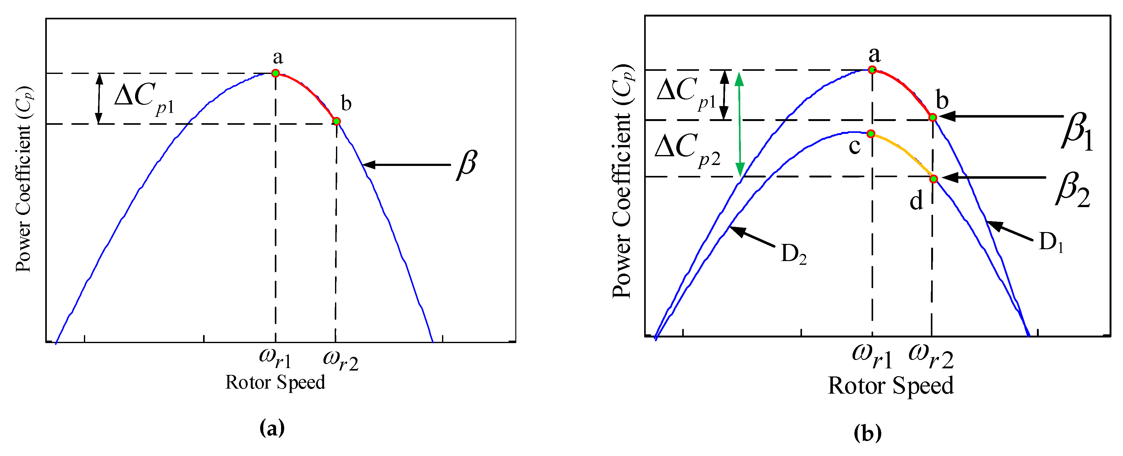
determines the “maximum power” that the wind turbine can absorb from the available wind power for a given wind turbine at a given wind speed. It is a function of the tip-speed ratio
λ and the pitch angle
β. A typical curve of
is illustrated in
Figure 2.
As can be seen in
Figure 2a that the power coefficient
reduces from
to
as the rotor speed of wind generators increases from
to
at a given
β, which causes the reduction of the captured wind power
. The generator speed acceleration can be achieved by reducing the electromagnetic torque with the proper control strategy of RSC. The dynamic response of the generator rotor can be described by Equation (
6), where
and
J are the generator rotor speed and the moment of inertia of the rotating mass connected to the rotor, respectively.
and
are the mechanical torque and electromagnetic torque, respectively.
The increase of the rotor speed converts the partial wind power into the rotor inertia energy. The stored mechanical energy
in the generator rotor at time
t is relevant to the increase of the rotor speed, given by:
The acceleration of the rotor speed reduces the surplus power flowing to the rotor speed by reducing the captured wind power and convert partial captured wind power into the inertia energy in the rotor inertia, as shown in Equation (
7). Under the stator-flux oriented reference frame, the decrease of
causes the decrease of the q-axis active current in the rotor immediately [
14]. Thus, the proposed control strategy of RSC reserves considerable potential reactive power capacity for the RSC to participate into the voltage-reactive power control, which will further enhance the voltage support capability during voltage drops.
When the supply voltage seriously drops (e.g., 0.1 p.u.), the grid code in UK [
5] requires that the wind turbine must provide the maximum reactive current during serious grid faults to support the voltage. Thus, the whole capacity of RSC is dedicated to inject the reactive power to the grid. With this control strategy, the total amount of the reactive power from a large scale wind farm should be rather considerable, which probably leads to the favorable improvement of the voltage at the point of common coupling (PCC). Interestingly, if the voltage of the PCC is improved during the grid fault, it means that the stator voltage drop is reduced. Hence, the peak of the transient excessive power also declines [
28].
However, the generator speed can accelerate quickly since reduces to zero. The acceleration of the rotor speed may increase the thrust and centrifugal force, when DFIG is operating at or close to the rated speed. When applied to the rotor construction, this may endanger the wind turbine mechanical system. Thus, the acceleration of the rotor speed is finite due to the maximum allowable rotor operation speed. Moreover, the mass stored inertia energy is large if the rotor speed increases far beyond to the prefault value. Once the stored energy is released in a very short time duration, the large over-current will be induced without any special control. Therefore, it is preferable to keep the rotor speed close to the prefault value.
As shown in
Figure 2b, if the pitch angle increases from
to
, the
curve will transfer from curve D1 to curve D2. Accordingly, the power coefficient
reduces from
to
, which causes a perceptible reduction in the aerodynamic power extraction and mechanical torque. In addition to the increase of the rotor speed beyond the optimal value, an improved auxiliary pitch angle controller is proposed to reduce the captured wind power and suppress the over-speed of the rotor, when the amplitude of the supply voltage drop exceeds a certain threshold.
4. Reactive Power Control Strategy and Controller Design for DFIG-ESS
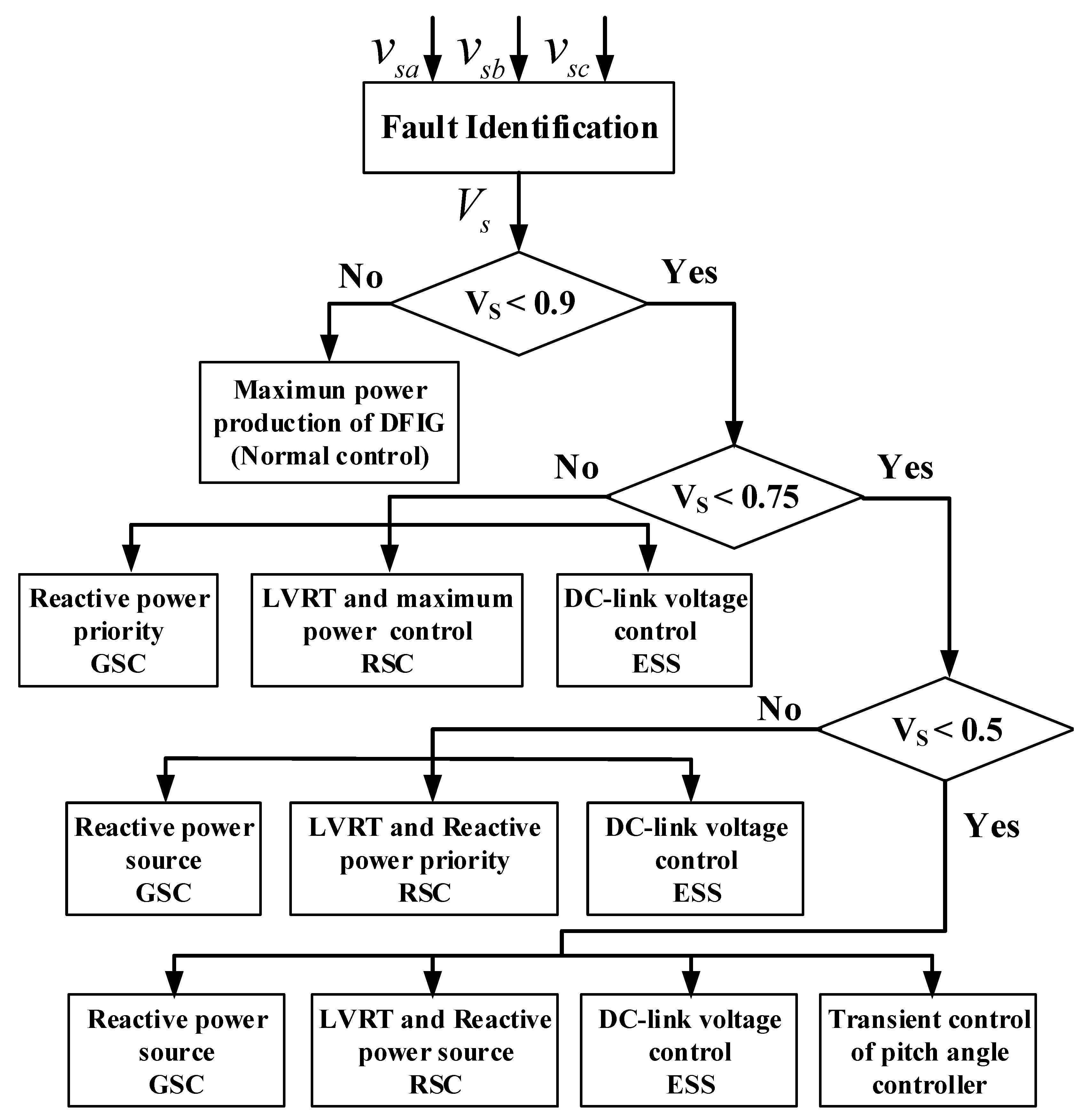
The transient response of DFIG-ESS varies with the different depth of voltage dips. Therefore, different control strategies can be designed for DFIG according to the depth of the voltage dip. The flow chart of the integrated LVRT and enhanced reactive power support scheme is shown in
Figure 3. It can be seen from
Figure 3 that the three-layer control strategy of DFIG is proposed according to the magnitude of the supply voltage during the fault period. Different control strategies of GSC, RSC, and pitch angle control are designed for different layers.
In
Figure 3, ESS is responsible for the DC-link voltage regulation during the normal and fault operations. When the supply voltage drops below 0.9 p.u., the RSC is used to control the maximum power production of the stator, while the GSC operates at the reactive power before participating into the voltage support. As the voltage drops between 0.75 p.u. and 0.5 p.u., the GSC acts as a reactive power source to inject the reactive power to the grid. The RSC is controlled to realize the LVRT capability and helps the GSC further enhance the reactive power capability of the DFIG under fault conditions. When the supply voltage suffers a serious voltage drop (e.g., below 0.5 p.u.), the whole capacities of RSC and GSC are used to deliver the reactive power to the grid to boost the AC voltage. Furthermore, an auxiliary transient pitch angle controller is proposed to protect the rotor and realize the LVRT capability of DFIG.
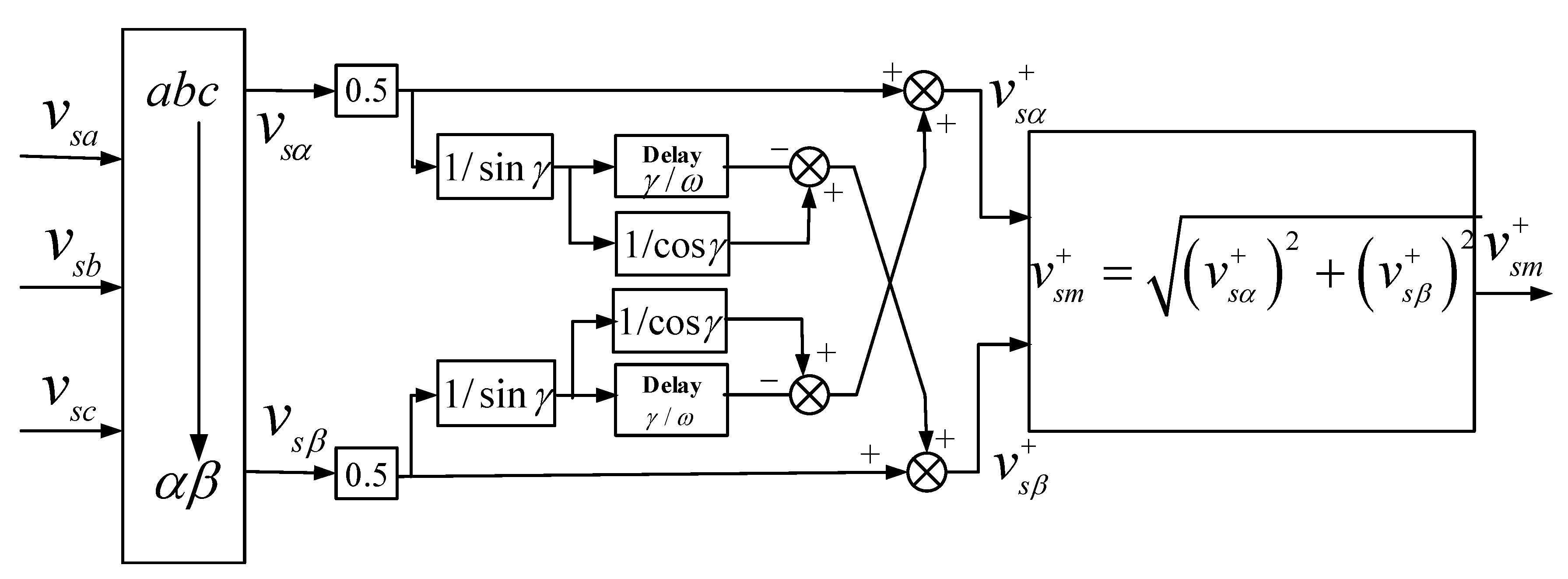
4.1. Grid Faults Identification
In order to rapidly switch the normal controllers to the LVRT controllers, a good monitoring of the supply voltage dip is a crucial issue in the implementation of the proposed control strategy for the DFIG [
30]. Different fast identification algorithms of grid voltage dip have been employed by several researchers [
12,
30]. In this paper, a sequence component decomposition method in [
12], where its accuracy and fast identification of voltage variables under balance and unbalance conditions have been verified, is implemented in order to detect the magnitude of the supply voltage. The block diagram of this method is shown in
Figure 4, where
γ is the delay angle. The amplitude (
) of the calculated positive sequence component of the stator voltage (
) can be derived as:
where
and
are the
α- and
β-axis positive sequence components of the stator voltage
, respectively.
4.2. Control Strategy of ESS
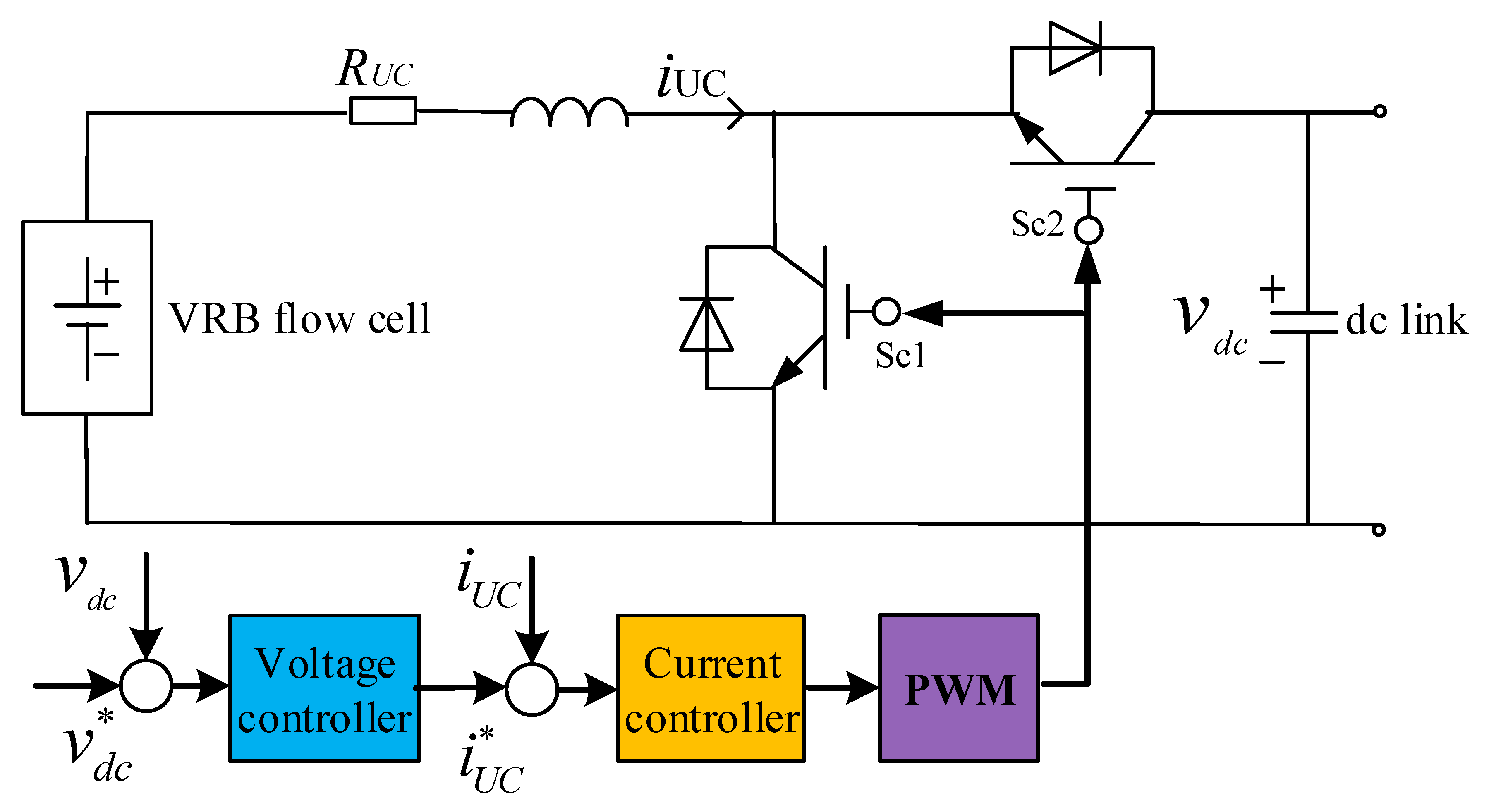
The ESS can be readily integrated into the design of the DFIG using a two-quarter IGBT-based DC/DC converter as described in
Figure 5. The control objective of the ESS is to regulate the DC-link voltage by keeping the power balance between RSC and GSC to make a good performance for the DFIG during normal and fault operations.
Figure 5 shows the overall vector control scheme of the ESS. The control strategy uses the cascade control, whereby slower outer control loops regulate d- and q-axis current reference set point and inner faster current loops regulate the current to track the reference current.
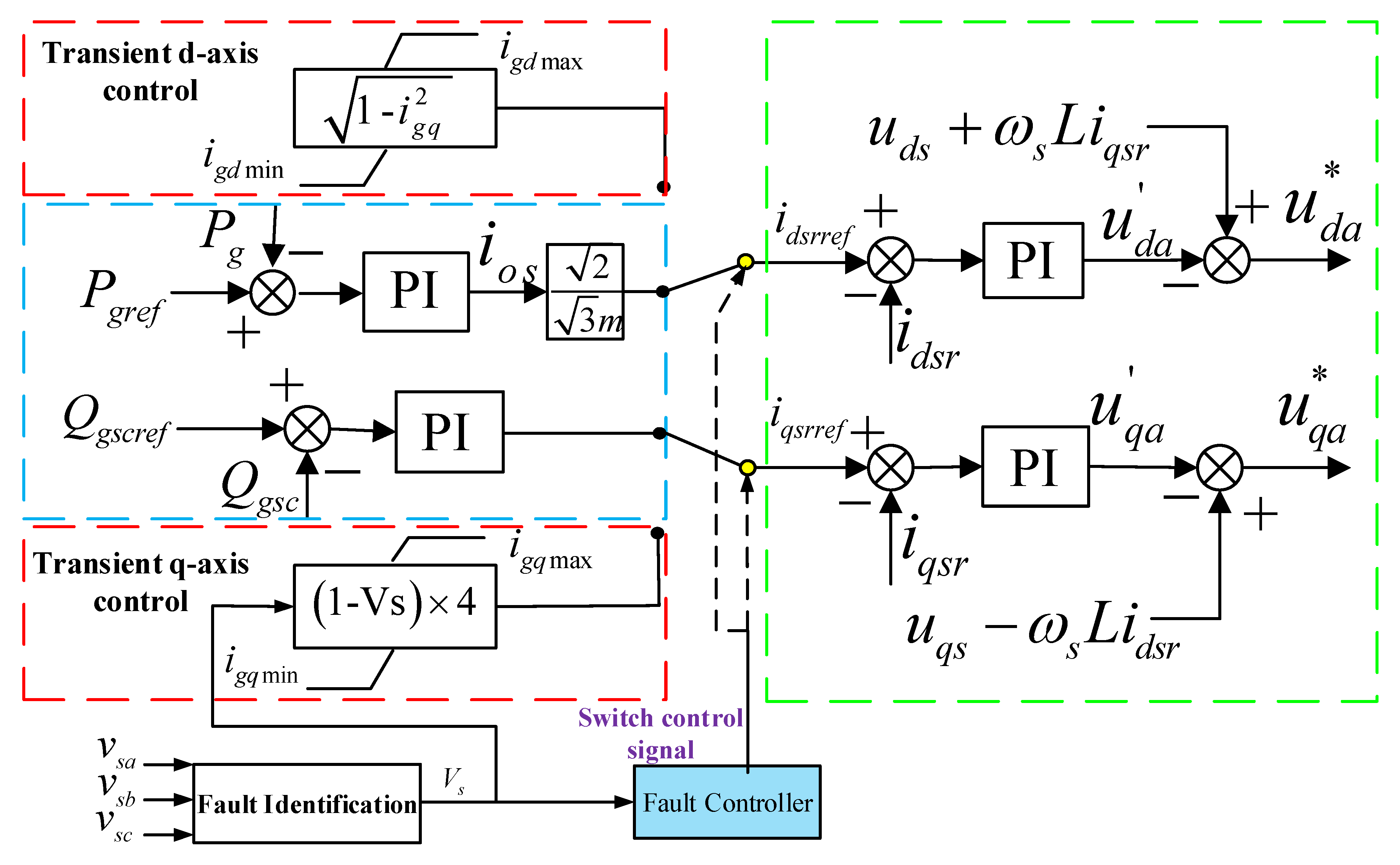
4.3. Controller and Reactive Power Control Strategy of GSC
The GSC can be free from managing the DC-link voltage since ESS is responsible for the DC-link voltage regulation. The control strategy used in [
23] is applied here to modify the active power outer loop of the GSC, where the output active power of DFIG is regulated to the command value that comes from the system operator. It can also provide a limited reactive power support. Normally, the reference reactive power can be set to zero for the unity power factor operation for economic operations. The overall vector control scheme of the GSC during the normal operation is shown in
Figure 6.
Based on Equation (
4), the relation between the currents of RSC (
), GSC (
), and ESS (
) can be derived as:
where
m is the factor of the PWM modulation depth.
It is known from (
9) that the ESS maintains the DC-link voltage constant. This is also equivalent to regulate the current balance between
and
. If the controller of ESS is fast enough, the DC-link voltage can be kept constant even if
or
reduces to zero. This reserves considerable potential reactive current capacity for GSC to participate in the voltage support during voltage sags. Therefore, it is proposed that the GSC can be contributed to the voltage support by injecting 4% reactive current for 1% supply voltage drop when the supply voltage falls below 0.9 p.u. to satisfy the requirement of grid codes, while the residual current capacity of GSC is used to deliver the active current to the grid.
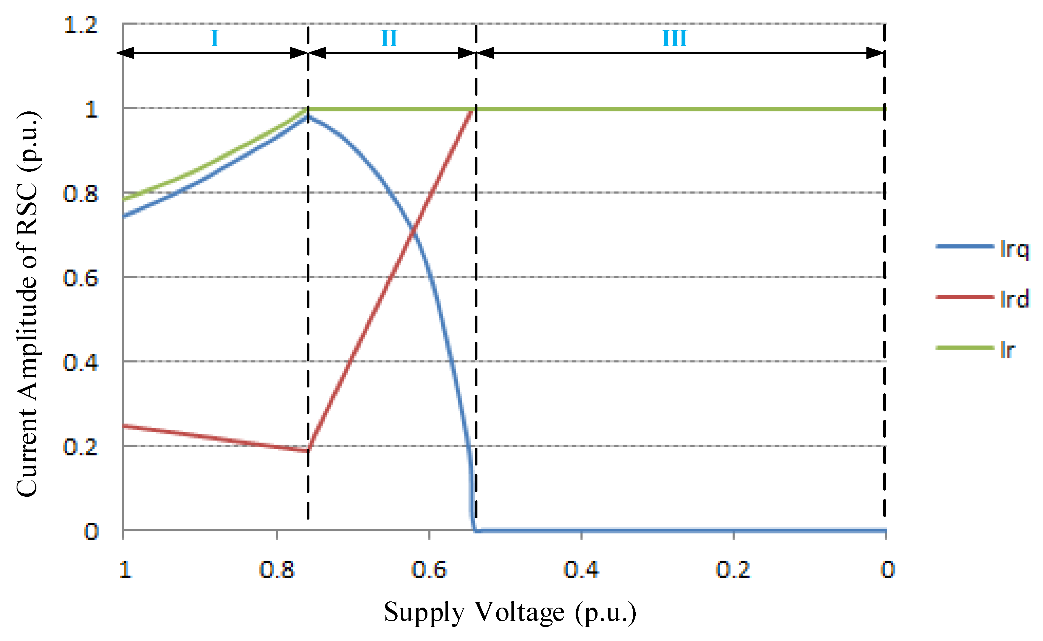
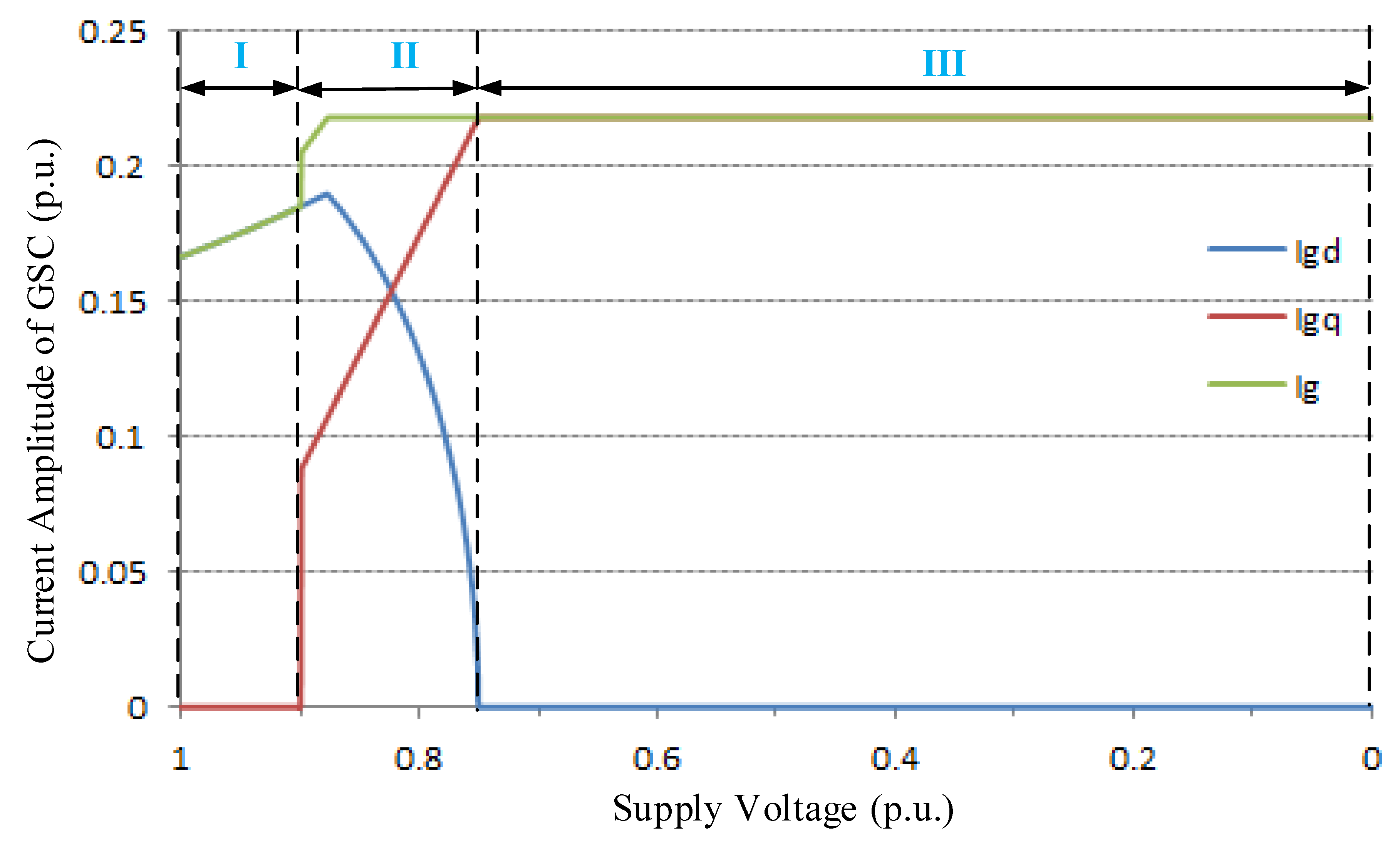
Figure 7 shows the coordinated control strategy of
and
for GSC during grid fault under the rated power active production condition as this is the most onerous situation that can be experienced by a wind turbine. The control strategy with a slight modification can meet the regulation of the other scenario.
Three different operation stages are observed in
Figure 7. In Stage I,
increases from the initial value of 0.17 p.u., while
maintains zero to deliver its rated active power at the unity power factor as the supply voltage drops from 1 p.u. to 0.9 p.u.. As the supply voltage continues to drop below 0.9 p.u. in Stage II,
starts to linearly increase from 0.4 p.u. by 4% for each 1% reduction in the supply voltage magnitude.
must decrease so that the grid current is constrained within the limits of semiconductor switches to ensure
. Consequently, the active power output of GSC is partially sacrificed for the sake of the reactive power injection. Finally, when the supply voltage drops to 0.75 p.u.,
equals to 1.0 p.u. and
reduces to zero, which means the GSC acts as a reactive power source and the power flowing into the rotor circuit is completely absorbed by the ESS.
For the GSC, the dynamic response of the outer power control loop is slower than that of the inner current control loop [
28]. Thus, a single inner current control loop is proposed to provide a fast initial reactive current injection following the voltage drop which can help fulfill dynamic demanding requirements.
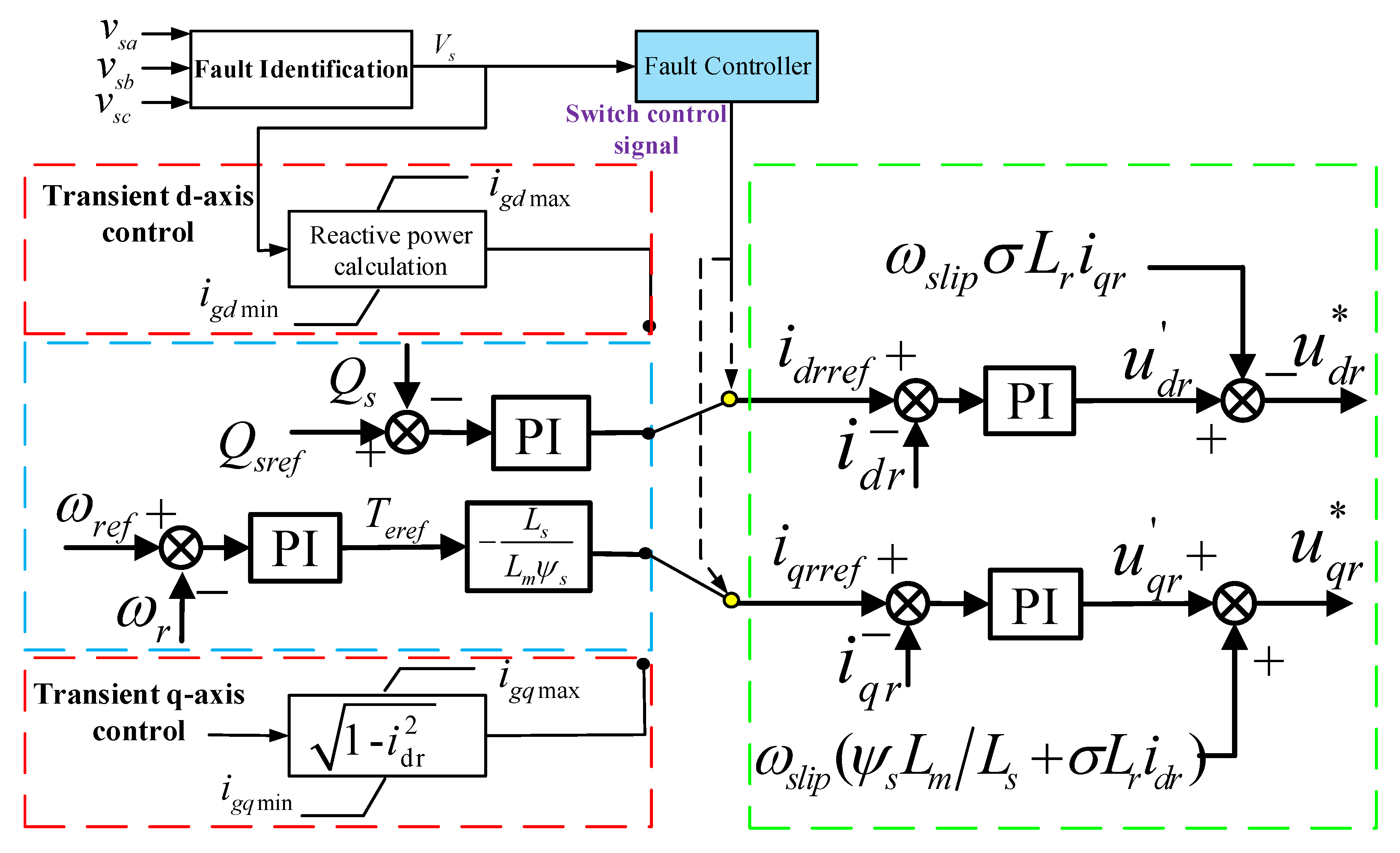
4.4. Controller and Reactive Power Control Strategy of RSC
In the normal mode, the RSC is used to extract the maximum available wind power and regulate the stator voltage (reactive power) in a decoupled manner. Accordingly, the block diagrams of the controllers are presented in
Figure 8, where dual-loop controls of torque-current and reactive power-current are applied in q- and d-axis, respectively.
The independent control of the stator active power (
) and reactive powers (
) can be achieved through regulating the q-axis current (
) and d-axis current (
) of rotor current, given by:
Normally,
equals to 75% of the current capacity of the RSC when DFIG extracts rated power at the unity power factor, and
can be kept constant by increasing
to compensate the voltage dip during fault conditions. Therefore, it is proposed here as shown in
Figure 8 that the DFIG works at the rated power production when the magnitude of voltage remains between 0.75 p.u. and 1 p.u..
When the voltage drops below 0.75 p.u., the output power of the stator is seriously decreased since the current of RSC reaches its limitation. This leads to a significantly instantaneous imbalance power between the incoming power from the wind and the power flowing into the grid. It has been analyzed above that the key point to realize the LVRT is to reduce the imbalance power flocking into the DFIG during grid faults. The imbalance power can be reduced by decreasing the captured wind power, which can be achieved by increasing the generator speed to make the operation mode of DFIG shift to the non-optimal operation.
The electrical torque
can be expressed as a function of q-axis current of RSC as shown in
Figure 8, given by:
One can easily deduce that the reduction of electrical torque can be obtained by reducing the active current (). The imbalance torque between the electrical torque and the mechanical torque causes the acceleration of the generator speed and consequently reduces the captured wind power. Besides, the increase of the rotor speed converts the partial wind energy into the rotor kinetic energy, which further reduces the imbalance power flow through the DFIG. Therefore, the transient over-current is not induced. DFIG can keep the continuous operation during gird faults. Moreover, the reduction of the during fault condition reserves considerable potential reactive power capacity for the RSC to participate in the voltage control. It further enhances the voltage support capability of GSC which is limited as the voltage drops to a low value.
In order to meet the reactive power requirement by the stringent grid code, the RSC changes into the reactive current priority where the
increases by 4% for 1% drop of the supply voltage amplitude while
is reduced to make the rotor current constrained within the limits of the RSC. A single control loop is also applied for RSC to make a fast response. The block diagrams of RSC controllers during the fault transient are shown in
Figure 9.
It can been seen from
Figure 8 that the active power reduces to zero as the supply voltage drops to 0.5 p.u. and consequently
also reduces to zero which causes the over-speed of the generator rotor and over-current in the stator after the fault clearance. This problem is addressed in the flowing subsection.
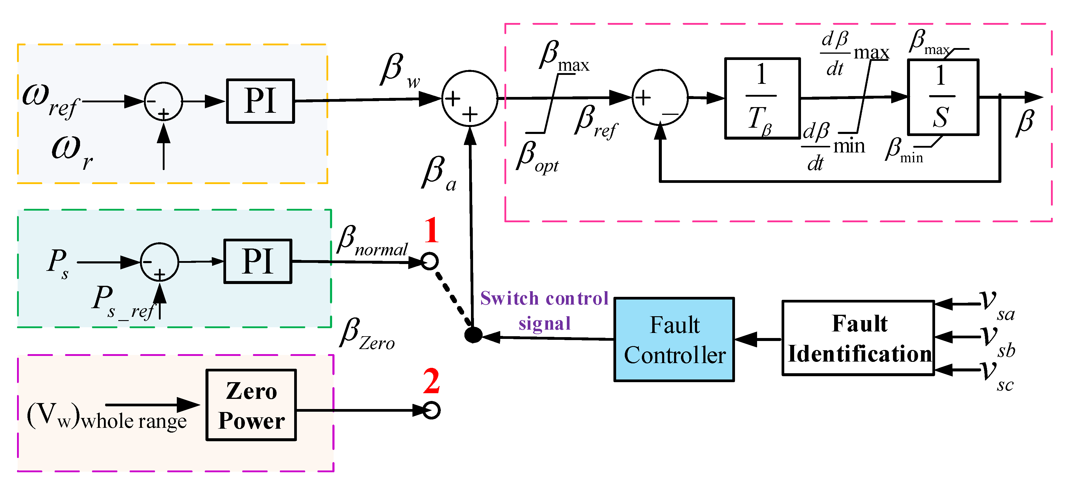
4.5. Pitch Angle Controller
Based on Equation (
6), the relation between the angular rotor speed, the captured wind power, and output power of DFIG can be obtained:
This formulation shows that the generator speed decreases due to the decrease of
. Compared to the generator speed, the increase of pitch angle has a more significant impact on the reduction of aerodynamic power extraction. Generally, the mechanical servo system is able to change the pitch angle of the blades at a rate around
[
31]. This indicates that the pitch angle can be only altered several degrees during the grid fault transient (0.6–1s). For a given wind speed, if the blade pitch angle increases from 0 degrees to 10 degrees, the power coefficient drops from 0.48 to around 0.20 in a second. Consequently, the captured wind power decreases around 30% [
32].
For the conventional PI controller, the wind turbine blade pitch angle is not controlled until the upper generator speed or rated power is reached. Therefore, it cannot effectively help in the reduction of the captured wind power. It can be seen from Equation (
12) that if the captured wind power is reduced as soon as possible, the maximum generator speed will be significantly decreased. Consequently, the maximum generator speed and the over-current after fault clearance are seriously suppressed. Therefore, an auxiliary improved pitch angle controller (as shown in
Figure 10) is proposed. For this improved pitch angle controller, the turbine blade pitch angle is controlled at the instant of voltage dips, when the generator speed is below the rated speed.
The switcher works at position 1 in the normal operation to prevent over-rated power production under high speed winds. As the amplitude of the supply voltage is below a certain threshold (0.5 p.u.), the fault controller is triggered to change the switcher to position 2. Thus, the pitch angle increases at the maximum rate to the desired value which is obtained from the zero power block storing the pitch angle values corresponding to zero power output of the turbine over the whole range of wind speeds.
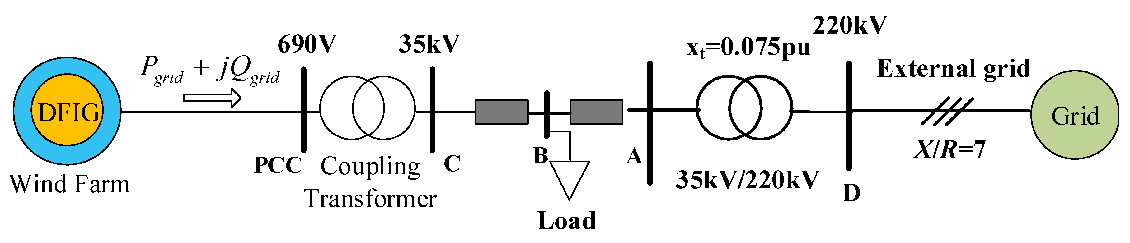
5. Case Studies
In this section, simulations are carried out on a single-machine-infinite-bus system (as shown in
Figure 11) with a 1.5 MW DFIG based wind farm to validate the proposed method in enhancing the LVRT capability of the DFIG as well as supporting the terminal voltage during grid faults. Three different cases are studied as follows:
Case 1: examining the LVRT capability of the DFIG-ESS with the proposed control strategy during serious balanced voltage drops.
Case 2: evaluating the reactive power support capability of the DFIG-ESS during serious unbalanced voltage drops.
Case 3: evaluating the maximum power production of the DFIG-ESS during low-level voltage dips.
Case 4: investigating the reactive power support capability of DFIG-ESS during medium-level voltage dips.
5.1. Case 1: LVRT Capabilities of DFIG With Serious Balanced Voltage Drops
Besides the case where the proposed method (Method A) is used, the conventional crowbar protection (Method B) is also employed during grid faults to give comprehensive comparisons. For the crowbar protection, the resistor is chosen to be 0.5 p.u.. The crowbar threshold is set to 1.5 times of the rated current. Note that the DC-chopper which is usually installed with the crowbar circuit in the method B is not used here, in order to investigate the capability of the ESS in controlling the DC-link voltage.
The RSC is controlled to extract the rated power and maintain zero reactive power output of the stator during the normal operation, which is corresponding to the super-synchronous operation mode of DFIG. A three-phase 85% supply voltage drop of 625 ms duration is assumed to occur at Bus B at t = 2 s.
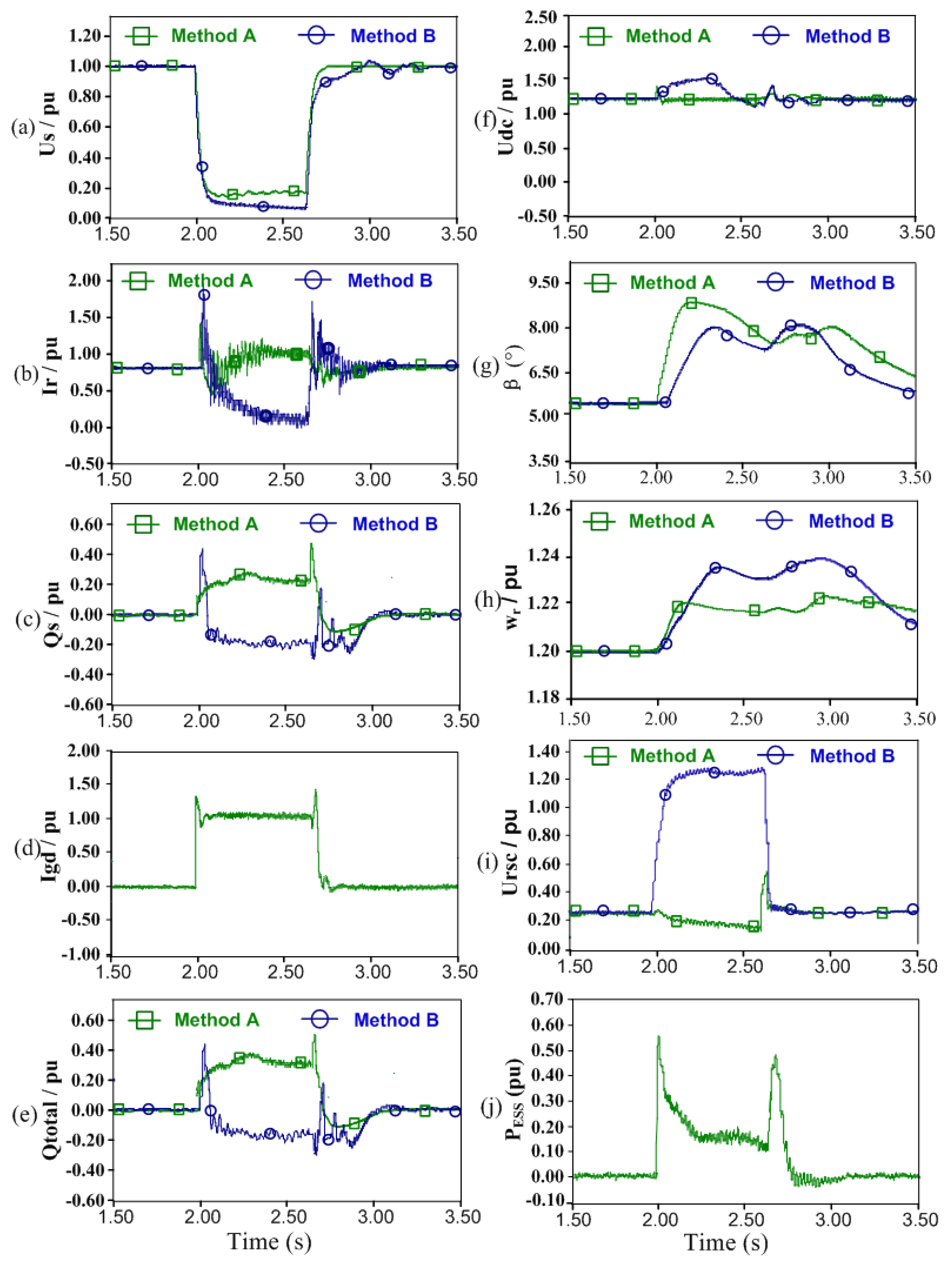
The transient behaviors of the DFIG with two different control strategies A and B with serious balanced voltage drops are depicted in
Figure 12. It is observed that the transient behaviors in the case of Method A are better than those in the case of Method B. The rotor current and DC-link are suppressed below the crowbar threshold with Method A (see
Figure 12a,f). The DFIG can keep the continuous operation without the interruption of the crowbar and participate into the voltage support by injecting the reactive power to the grid (see
Figure 12c,e). However, the DFIG with Method A starts to draw the reactive power from the grid (see
Figure 12c). This reactive power consumed by the DFIG further reduces the voltage of the DFIG stator terminals (0.1 p.u. as shown in
Figure 12a). This is not acceptable when considering the grid codes [
11]. Moreover, Method A can response much faster to increase the pitch angle than Method B. It indicates less unbalance power flow into rotor and less power stored in the rotor inertia energy. Consequently, the voltage on RSC, the maximum generator speed, and stator and rotor current after fault clearance in Method A are less than those in Method B.
The comparative analysis is investigated to evaluate the effectiveness of the
ratio of the 220 kV/500 kV transmission grid on the transient voltage support capability of DFIG by using the proposed control strategy.
Table 1 compares the improvements of voltage profiles at bus D with different
ratios of the external grid impedance. As can be observed in
Table 1, the voltage improvement at bus D increases to a high level with the
ratio at the fixed reactive power output of DFIG. Hence, the proposed control strategy of DFIG has a positive impact on the voltage improvement of the transmission grid during the fault period.
5.2. Case 2: Reactive Power Support Capabilities of DFIG With Serious Unbalanced Voltage Drops
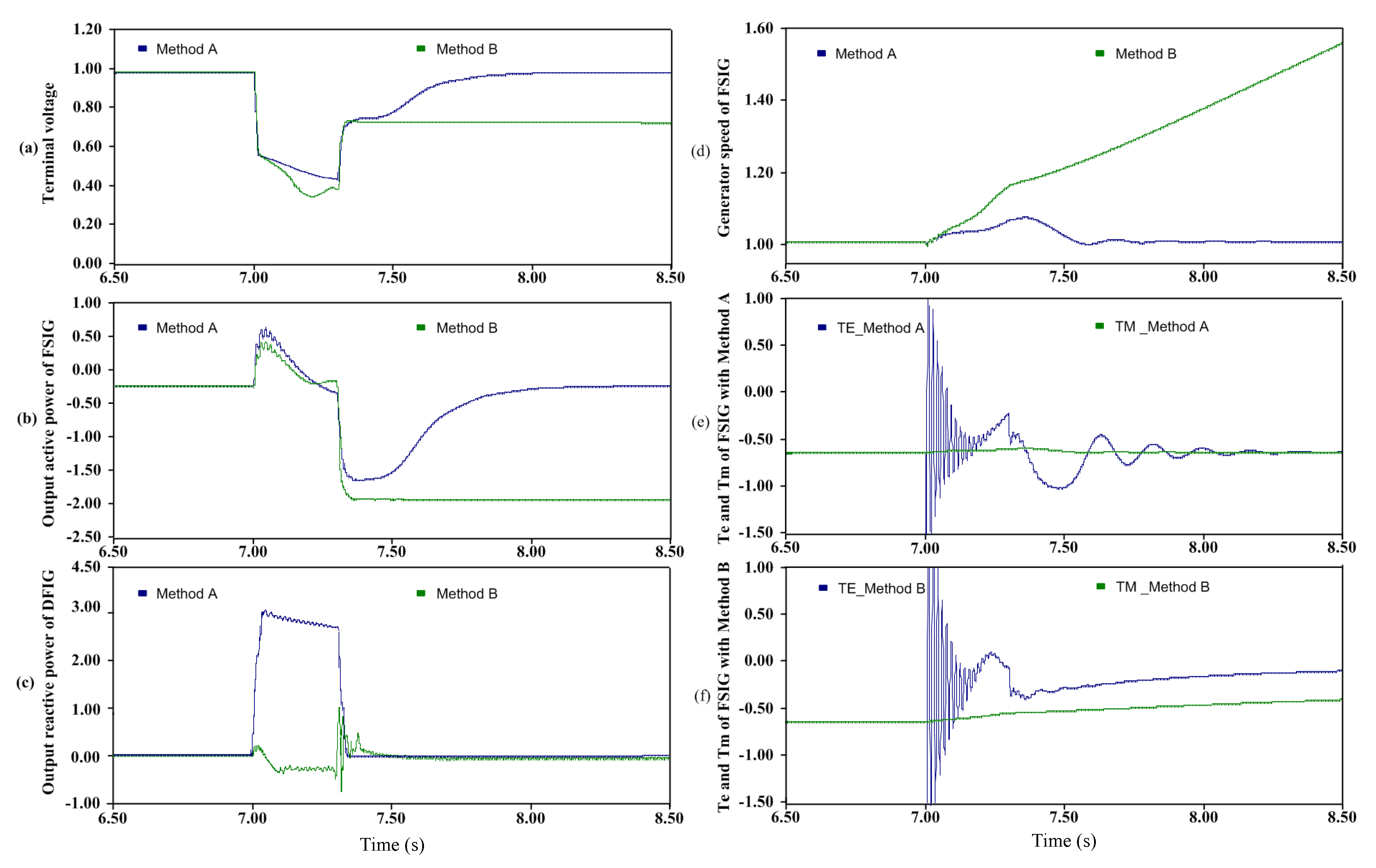
This simulation case is performed to further verify the LVRT and reactive power support capabilities of DFIG by using the proposed control strategy. The LVRT capability of the fixed-speed induction generator (FSIG) nearby the DFIG is improved when the unbalanced serious voltage drop occurs. In
Figure 11, a 1.5 MW FSIG is connected at bus B and the DFIG in this case presents a 12 MW wind farm. Under the normal operation, the FSIG speed is set as 1.01 p.u. with the active power output 0.4 p.u. and the reactive power absorption capability of 0.17 p.u. At time
t = 7 s, a two-phase ground short circuit fault occurs with the duration of 300 ms at bus B. The voltage drops to about 0.6 p.u. The simulated transient behaviors of the FSIG when the DFIG-based wind farm is controlled by the proposed control strategy (Method A) are compared with those when the DFIG-based wind farm is controlled by the conventional design strategy (Method B), as shown
Figure 13.
In
Figure 13, the DFIG-based wind farm can deliver about 1.86 p.u. reactive power to the grid by using Method A, while the DFIG-based wind farm absorbs approximately 0.35 p.u. by using Method B [see
Figure 13c]. Consequently, the terminal voltage with Method A is higher than that with Method B during the unbalanced grid faults [see
Figure 13a]. The generator speed with Method B accelerates faster than that with Method A due to the larger torque difference between the electrical torque and mechanical torque [see
Figure 13d–f]. It is observed the terminal voltage with Method B remains relatively low because of the high reactive power consumption by the FSIG after the fault [see
Figure 13b]. Consequently, the electrical torque of FSIG is always smaller than the mechanical torque, and its speed continues to increase, which makes the voltage collapse [see
Figure 13f]. Finally, the FSIG fails to ride through the unbalanced fault when the DFIG is controlled by Method B without the reactive power support during the fault period. In contrast, due to the lower acceleration of the generator speed and the higher initial voltage recovery with Method A, the electrical torque is larger than the mechanical torque [see
Figure 13f]. Thus, the generator speed starts to decrease [see
Figure 13d]. As a result, both the generator speed and terminal voltage of the FSIG [see
Figure 13a] restore to the prefault values when the fault is cleared.
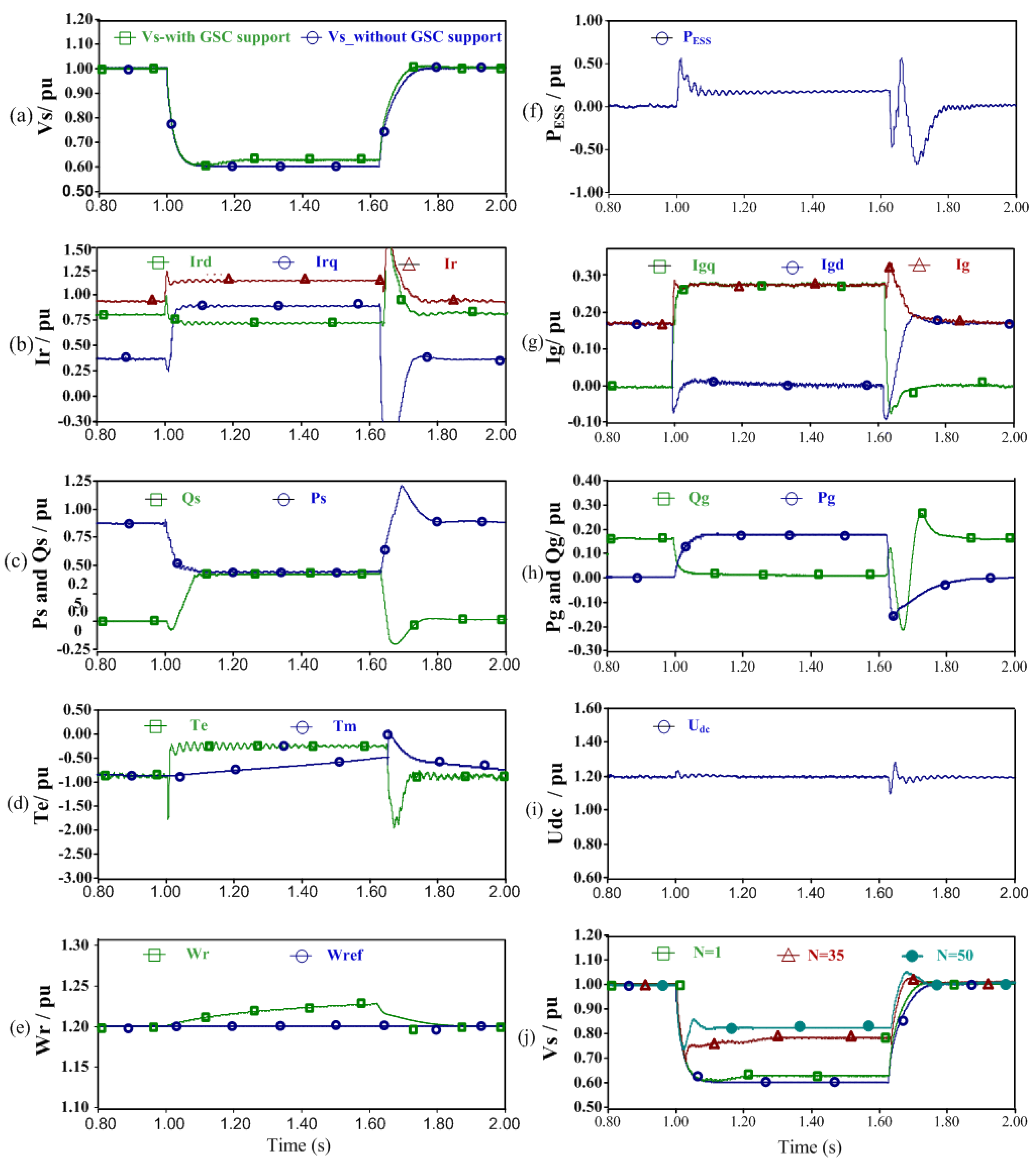
5.3. Case 3: Maximum Power Production of DFIG-ESS During Fault Period
This case is developed to assess the maximum power producing capability of the DFIG-ESS during fault period. The operation condition is the same as that in the previous case. The fault remnant voltage drops to 0.8 p.u. at t = 1.0 s.
The simulated responses of the DFIG-ESS with the proposed maximum power producing control strategy are shown in
Figure 14. As the fault takes place,
increases from 0.83 p.u. to 1.02 p.u. to maximum the active power that can be exported from the DFIG to the grid. The excitation current
reduces from 0.33 p.u. to 0.27 p.u. since the supply voltage drops (see
Figure 14c). The current of RSC is constrained within the current limitation (1.14 p.u.). Moreover, the electromagnetic torque is kept constant due to the increase of
. The generator speed does not accelerate during this period (see
Figure 14d). In order to satisfy the grid codes requirement, the GSC injects 0.21 p.u. reactive current to the gird which accounts for 80% of the capacity of GSC. The active current of GSC reduces from 0.17 p.u. to 0.15 p.u.. Hence, the current carrying capacity of GSC does not exceed. Accordingly, the output active power of the GSC decreases from 0.17 p.u. to 0.13 p.u.. The reduction of the output power of GSC is quickly absorbed by the ESS in
Figure 14d, which keeps the DC-link voltage stable (see
Figure 14e).
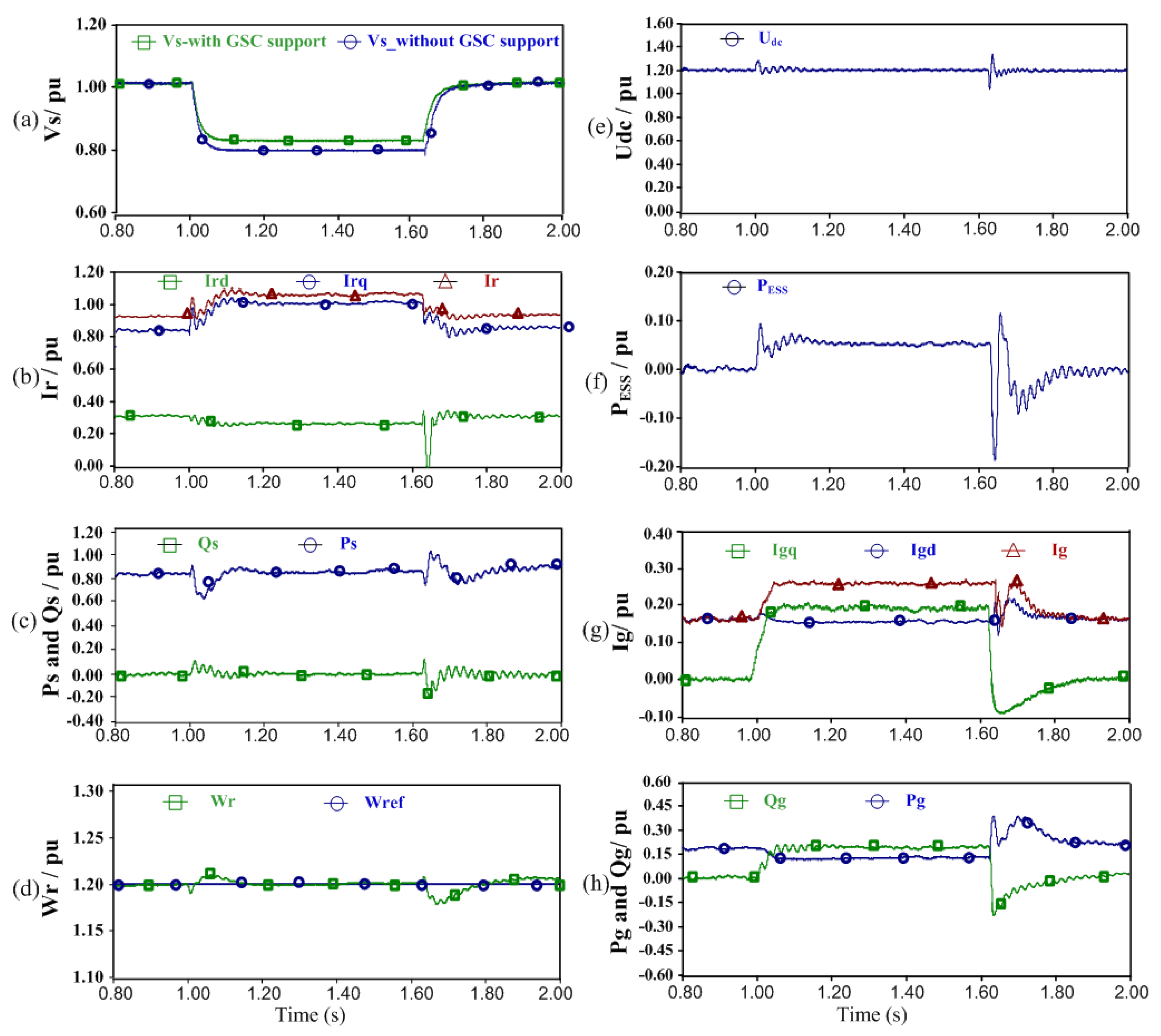
5.4. Case 4: Reactive Power Support Capability of DFIG-ESS During Voltage Dips
This simulation test is used to further verify the reactive power support capability of DFIG-ESS during grid voltage sags. The operations of the RSC and GSC are the same as those in Case 2, and 625ms three phase fault with remnant voltage of 0.6 p.u. occurs on bus B.
Figure 15 shows the system response of the DFIG-ESS with the reactive power support priority scheme.
Figure 15b shows the reactive power priority of the DFIG-ESS during voltage dips. It is obvious that the priority of the RSC gives the reactive current to support the supply voltage recovery upon the fault occurs. The reactive current increases from 0.33 p.u. to 0.90 p.u., while the active current decreases from 0.83 p.u. to 0.70 p.u.. The current of RSC is constrained within its limitation. As a result, the reactive power increases to 0.45 p.u. while the active power reduces from 0.83 p.u. to 0.45 p.u. (see
Figure 15c). The reduction of active current causes the decrease of the electromagnetic torque, which results in the gradual increase of rotor speed from 1.20 to 1.22 p.u.. However, this is not serious. Furthermore, the GSC is acted as a reactive power source to boost the supply voltage (see
Figure 15f,g), since the rotor power can be handled by the ESS (see
Figure 15e).
Generally, the improvement of Method A in the nadir part of the voltage is very limited when the wind farm is simulated by only one DFIG. The provided reactive power is limited (see
Figure 15a). However, it is very clear from
Figure 15j that such voltage enhancement becomes increasingly obvious as the number of the DFIG in the wind farm increases. Therefore, the promising prospects of applying the proposed method to large scale wind farms are confirmed for voltage support during the grid faults.


