
Robust Frequency and Voltage Stability Control Strategy for Standalone AC/DC Hybrid Microgrid


1
School of Electronics and Information Engineering, Kunsan National University, Kunsan 573-540, Korea
2
Department of Control and Robotics Engineering, Kunsan National University, Kunsan 573-540, Korea
*
Author to whom correspondence should be addressed.
Energies 2017, 10(6), 760; https://doi.org/10.3390/en10060760
Submission received: 21 March 2017
/
Revised: 18 May 2017
/
Accepted: 25 May 2017
/
Published: 30 May 2017
(This article belongs to the Special Issue Advanced Operation and Control of Smart Microgrids)
Abstract
:The microgrid (MG) concept is attracting considerable attention as a solution to energy deficiencies, especially in remote areas, but the intermittent nature of renewable sources and varying loads cause many control problems and thereby affect the quality of power within a microgrid operating in standalone mode. This might cause large frequency and voltage deviations in the system due to unpredictable output power fluctuations. Furthermore, without any main grid support, it is more complex to control and manage the system. In past, droop control and various other coordination control strategies have been presented to stabilize the microgrid frequency and voltages, but in order to utilize the available resources up to their maximum capacity in a positive way, new and robust control mechanisms are required. In this paper, a standalone microgrid is presented, which integrates renewable energy-based distributed generations and local loads. A fuzzy logic-based intelligent control technique is proposed to maintain the frequency and DC (direct current)-link voltage stability for sudden changes in load or generation power. Also from a frequency control perspective, a battery energy storage system (BESS) is suggested as a replacement for a synchronous generator to stabilize the nominal system frequency as a synchronous generator is unable to operate at its maximum efficiency while being controlled for stabilization purposes. Likewise, a super capacitor (SC) and BESS is used to stabilize DC bus voltages even though maximum possible energy is being extracted from renewable generated sources using maximum power point tracking. This newly proposed control method proves to be effective by reducing transient time, minimizing the frequency deviations, maintaining voltages even though maximum power point tracking is working and preventing generators from exceeding their power ratings during disturbances. However, due to the BESS limited capacity, load switching (load shedding scheme) as last option is also introduced in this paper. Simulation results prove the effectiveness of the proposed control strategy from both frequency and voltage perspectives.
1. Introduction
Recently, remote microgrids (MGs) [1] have been widely developed, especially for rural and distant areas, where providing electric energy from the main utility grid is costly and has destructive environmental effects. With increasing environmental awareness, renewable generation penetration has increased gradually [2,3,4,5,6]. There are several MGs already installed for providing the electricity for rural areas [7,8,9,10,11,12]. However, microgrid control in standalone mood is more difficult than in grid connected mode because they are vulnerable to frequency and voltage deviations as they are isolated power systems that have smaller equivalent inertia, more dynamic complexity, and a weaker grid than conventional utility power grid and furthermore, the distributed energy resources have an intermittent nature. Therefore, if a mismatch between generation and load occurs, deviation of the microgrid frequency and voltage from the standard value is unavoidable. In standalone mode, some microgrid resources should compensate this fluctuation in generation (wind power and solar irradiation) and load.
Several research studies have examined methods to support frequency and voltage control. In [13], a frequency droop control was applied to photovoltaic (PV) power generation. In [14], techniques enabling wind power to operate in a manner similar to a conventional power plant were suggested to dispatch power at the operator’s request. However, frequency control strategies using intermittent renewable generation are not economically profitable as these systems are unable to maximize their free energy utilization ability.
Several other researchers [15,16,17] have focused on droop control techniques for frequency and voltage stabilization. Reference [18] involves an alternative droop control method for synchronous generators operating with voltage source converters (VSCs) by treating generators like VSCs, but the system stability and dynamics are highly affected by the selected droop gains. Furthermore, microgrids can face oscillations and instabilities due to high droop gains to achieve accurate power sharing, whereas, our newly proposed control method can be an economical replacement of the abovementioned droop control techniques used in different forms with diesel generators (DGs) as a droop controller regulates the generator output gains, which makes it unable to operate at maximum efficiency. Also, with droop control we have to neglect maximum power tracking to extract the maximum possible power from renewable sources to stabilize dc link voltages, but in our designed microgrid model, we can stabilize the voltage and frequency even after using maximum power point tracking (MPPT) and DGs at maximum efficiency. Furthermore, as the declining feature of the droop controller has only one regulatory parameter, so more than one control target cannot be reached.
Recently, some researchers have proposed methods to support the frequency and voltage in a multisource microgrid that includes renewable distributed generation and energy storage systems. In [19], an improved grid-forming control scheme is developed, which can keep the charging voltage of a battery bank under control without physical communication. In [20,21], a coordinated control architecture for power management of standalone microgrids is presented in which power control of each generation unit can be achieved with seamless mode changes. However, the results of these studies show that frequency deviation from the nominal value is very high. Moreover, the existing control strategies greatly increase the complexity of microgrid energy management. Therefore, it is necessary to develop an efficient and intelligent stability control approach with high applicability and reliability, where the operation modes and power supply scheduling can be regulated according to power sources, load condition and battery state of charge.
Keeping in mind the aforementioned difficulties, this paper introduces a new control strategy that comprises battery energy storage system (BESS)-based frequency and voltage stabilization along with supercapacitors and a fuzzy logic-based intelligent control system for energy management in generation and load imbalance conditions. The BESS will assist in preventing the system frequency from deviating far from its nominal value. The supercapacitor is used to maintain the DC bus voltage by consuming big current spikes generated due to intermittent nature of renewable sources and maximum power point tracking. Power stored in the supercapacitor is used to charge the BESS when required. The fuzzy logic-based supervisory controller will maintain the frequency and voltage at the nominal value and also control dump loads in a positive way and load shedding scenarios in severe cases to avoid microgrid collapse.
The main architecture of the proposed system is composed of: a PV-based distributed generation, small wind turbine system (WT), synchronous diesel generator (SG), battery energy storage system, DC heat generation system as dump load, fuzzy logic based supervisory control and management system, bidirectional buck-boost converter, super capacitors, inverter between DC and AC (alternating current) bus. The whole system is then connected with the various primary and secondary loads as shown in Figure 1.
2. Hybrid AC/DC Microgrid Model
This paper focuses on a standalone hybrid microgrid based on wind turbine generator, PV system, DG, supercapacitor, BESS, primary and secondary AC loads, DC heat generation system as dump load and a fuzzy logic-based supervisory controller for power management, frequency and voltage stability. Figure 1 illustrates the proposed hybrid microgrid model. As shown, distributed resources are connected to AC/DC bus by power electronic devices such as AC/DC converters, DC/DC boost converter and DC/DC buck boost converter for the battery energy storage system. The microgrid system design parameters are listed in Table 1.
Total power generation of distributed resources, for supplying the demand side comprises the output power of the diesel generator, wind turbine, photovoltaic system and battery energy storage system as shown in Equation (1):
The power source on the AC side of the microgrid is a 70 kW diesel generator whereas the AC load is composed of a 116 kW primary load and two secondary loads of 45 kW and 20 kW respectively. Power sources on the DC side of microgrid are a 60 kW PV system, 10 kW wind turbine and a battery energy storage system with a rating of 30 kW. Power management and frequency/voltage stabilization is performed by a fuzzy logic-based supervisory controller. The hybrid microgrid is modelled using Simulink-Matlab to simulate system operations and control. The microgrid operates solely in standalone mode to demonstrate frequency and voltage deviations that result from power imbalance due to fluctuating renewable generation or varying loads.
2.1. Diesel Generator System
A diesel generator (DG) is a reliable backup source in case of an emergency like a power outage to prevent discontinuity of daily work activities. It is a source that can supply power demand up to rated power at constant frequency [22]. A DG usually is composed of a synchronous generator, excitation system and a diesel engine with governor. A 70 kW synchronous generator with its basic controlling principles is discussed here.
The DG is modeled in Simulink using the SimScape toolbox. A DG is a system that converts mechanical energy obtained from external source into electrical energy. The generator uses mechanical energy to force the electrical charge movement in its windings through some electric circuit. This flow is the reason for the generator’s electric current output. Power produced by a diesel engine is small without any load whereas with load, the machine speed decreases for a short time and the mechanical power input to the generator terminals also decreases.
The system stabilizes itself after a short period of time due to the operation of a speed control system and the power input to the generator stabilizes to the required level. Due to the operation of the excitation system [23], voltages at the generator terminals are also maintained at the load demand. If the load demand is greater than the generated power, then it eventually results in a decrease in the frequency of the output. In diesel engine governor block, the reference rotor speed is already defined and using a feedback system, the rotor speed of the generator is also input to get the error value between two speeds to perform the function of controlling fuel combustion which results in power with the desired frequency. The internal configuration of a diesel generator governor is shown in Figure 2.
2.2. Photovoltaic System
The PV array block from the Simulink SimPowerSystems toolbox is used in this work. Photovoltaic module “SPR-305-WHT” of “SunPower Inc.” is used. Technical data per unit for this module is as follows:
PPVModule = 305 W, VMPP = 54.7 V, IMPP = 5.58 A, SPV = 1.63 m2.
Here PPVModule represents the PV module power, VMPP and IMPP represent the PV module voltage and current at maximum power point. The PV system [24] output power can be varied due to solar irradiation. The total number of PV modules, modules in series and parallel can be calculated using Equations (2)–(4):
where NT represents the total number of modules, NS to be connected in series, NP in parallel, Vnominal is the rated voltage (220 V) and Ppvamax is the PV maximum size w.r.t power according to the irradiation, whereas, corresponding area of PVA can be calculated as:
where SPVModule represents the PV system single module area.
The PV generation system studied in this section is connected to an inverter through a boost converter, which is commonly used in a multi-source renewable energy systems. A boost converter [25] is used to regulate the voltages according to the supercapacitor requirements. The boost converter output is controlled by switching the IGBT’s (insulated-gate bipolar transistor) duty cycle.
As for PV maximum power point tracking (MPPT), over the years many MPPT techniques have been developed and implemented to extract the maximum available power from the solar photovoltaic system. These methods [26,27] vary in several aspects, including convergence speed, cost, effective range, hardware implementation and complexity. In this PV system, we use the incremental conductance technique to calculate the MPP. In this method, array terminal voltage is always adjusted according to the MPP voltage; it is based on the incremental and instantaneous conductance of the PV array.
2.3. Wind Turbine
Wind turbine is a system that converts wind’s kinetic energy into mechanical and then electrical power by driving machines and electric generators. The wind turbine model used in this study comprises a wind source, turbine aerodynamics model and permanent magnet synchronous generator (PMSG). The considered turbine model is a horizontal-axis turbine with three blades. The output power of a wind turbine can be calculated by Equation (6):
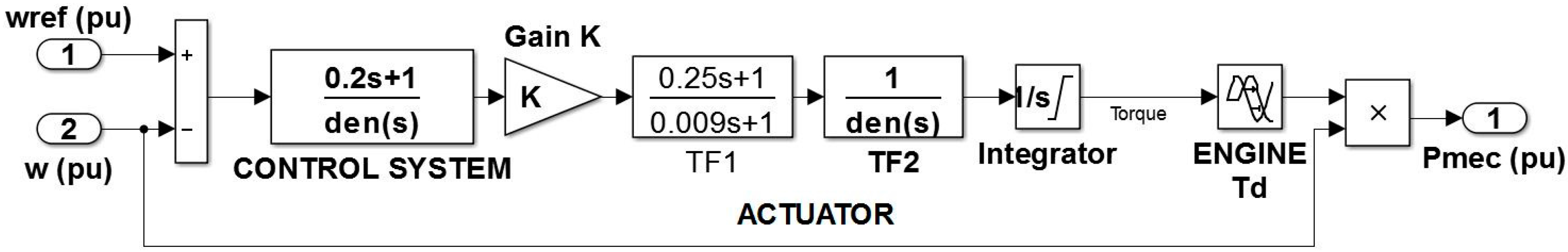
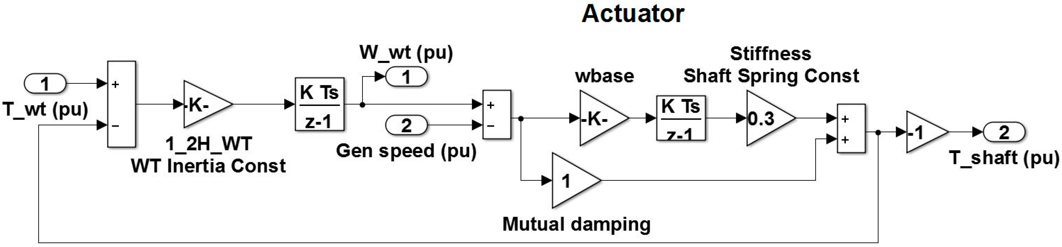
where ρ represents the air density (lb/ft3), νω represents the wind speed (mph), A is the rotor swept area (ft2) and Cp is the maximum power coefficient, which ranges from 0.25 to 0.45. Pitch angle for the pitch controller and wind speed are input to this module. The basic internal configuration of the wind turbine governor can be seen in Figure 3.
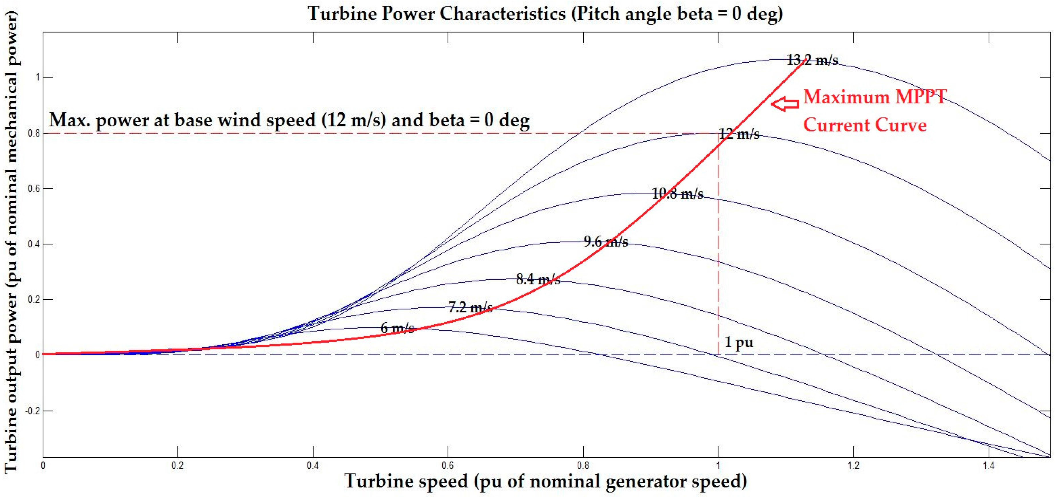
For WT maximum power point tracking, efficient and accurate current control technique [28] is used. This technique takes a reference current point according to system output voltages. Wind turbine generated voltages are directly proportional to wind speed. WTG characteristic curve is used to derive the reference current equation as shown in Figure 4.
The mathematical equations of this curve is derived by Matlab curve fitting tool. Furthermore, the calculated reference current points with respect to each voltage value are used in highly tuned PID (propotional-integral-derivative) controller to control the current independently.
2.4. Supercapacitor as DC Link
A supercapacitor is a high capacity capacitor with much larger capacitance as compare to other electrolytic capacitors. These capacitors can store almost 100times more energy than usual capacitors, can charge or discharge much faster than batteries and have longer lifetime.
Smooth energy flow can be achieved by using these capacitors with dc link. These capacitors are effective in containing big current spikes and high fluctuations. MPPT plays a vital role in extracting maximum available power from renewable sources but it causes high current fluctuations in intermittent nature of renewable sources. In this research work, supercapacitors are implemented with dc link to operate the designed system on best possible level [29]. Here, supercapacitors are connected is parallel with the DC-link via a DC/DC buck converter to maintain the DC-link voltage within the specified range while the system is operating at MPPT. The DC/DC buck converter is controlled by a standard PID controller, which is responsible for maintaining the DC-link voltage to 500 V DC. Further increases in voltage will be consumed and stored in current form in the supercapacitors. Stored power in supercapacitors is also used to charge the battery energy storage system.
2.5. Battery Energy Storage System
Li-ion rechargeable batteries are used to store surplus power generated by renewable energy resources and use this stored power in emergencies when the load demand is high or the renewable generation is low. Battery capacity in ampere-hours and battery power in kWhr can be calculated by Equations (7) and (8):
where Cbattery is the total capacity in Ah, Ebattery is the power to be supplied by the battery, Vbattery are the voltages of the battery, Pt is the total power to be supplied by the battery and T is the time in hr. Also the battery power can be calculated using battery terminal voltages and current as shown in Equation (9):
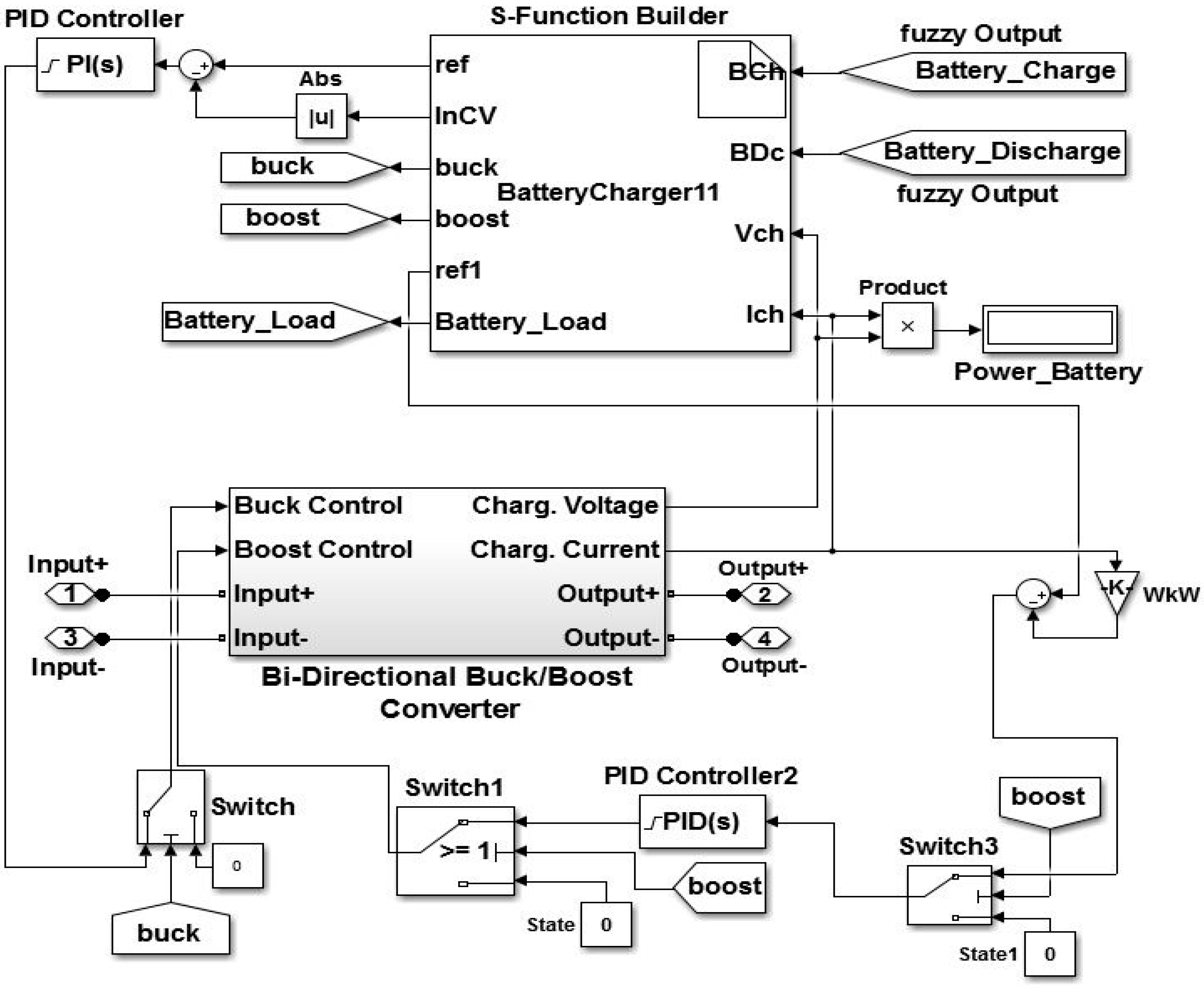
In this equation, Vbat and Ibat are the battery voltages and current, respectively. A 250 V, 120 Ah lithium-ion battery system is used in our proposed system. The battery SOC is limited to 50% as minimum discharging level. The efficient battery charging and discharging mechanism is shown in Figure 5 and explained below. As shown, a bidirectional buck boost converter is used to regulate the voltages according to the battery charging or discharging requirements. A PID controller is also part of the proposed system to adjust PI (proportional-integral) gains depending on the difference of error magnitude between modes to make the system performance smooth and efficient.
2.5.1. Bidirectional Buck Boost Converter
The purpose of the bidirectional DC-DC converter is to shift the input DC voltage and current to a desired output DC voltage or current such as for a given input voltage and current, the corresponding outputs can be different. In practice, voltage shifts are achieved by turning discrete switches on and off very fast, choppering the input voltages. Specifically if Vi > Vo, the device is working in buck mode and is a step-down converter, and if Vi < Vo then it’s in boost mode and is a step-up converter. In our designed model, the buck converter will work when surplus power is generated and needs to be stored in the battery storage system. We have a high voltage at the input side at that time; the bidirectional converter will work as a buck converter to step-down the voltages to the battery charging voltage level, whereas it will work as a boost converter in battery backup mode where we need to step-up the stored power voltages to synchronize with the DC link voltage level. Two PI controllers are used to control the stored voltage level and current limitation to avoid any damage.
2.5.2. Battery Charging Controller
The battery charger controller is designed to control the battery charging during constant current (CC) and constant voltage (CV) modes [30] in an effectual, systematic and dynamic way. Buck converter with charging voltages from DC link as input is used for BESS charging in CC-CV mode.
Charging current in CC mode and charging voltages in CV mode are maintained by buck converter. It provides maximum current and battery overcharging protection by shifting the battery from CC to CV mode when the battery voltage reaches to its gassing voltages. In this control system, a PI controller is used to regulate and adjust the PI gains when the battery charging shifts from CC to CV mode for smooth performance.
2.6. Dump Load Controller
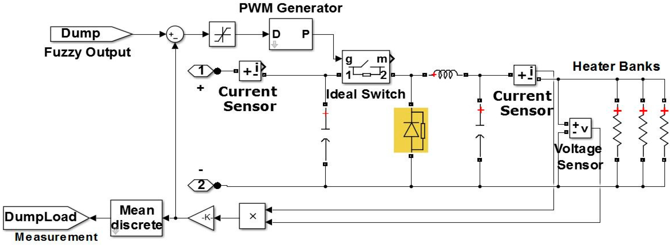
A dump load like a heat generation system [31,32] is installed in this work to ensure a safe and economic way to disperse surplus power produced by renewable systems to stabilize the system performance.
The dump load controller takes any extra power that needs to be consumed as input from the fuzzy logic-based energy management system as shown in the internal configuration of dump load controller in Figure 6. After that, this surplus power is consumed by several heater banks in the dump load block to keep the power flow in the system steady and efficient by generating heat.
2.7. Three Phase Inverter and Load Model
A sinusoidal pulse width modulation (SPWM) three phase inverter is used for DC-AC conversion in this system. A 175 kW AC load composed of a primary and two secondary loads is used in the proposed system. Two secondary loads of 45 kW and 20 kW can be turned on or off to assist frequency stabilization in case of emergency (low-frequency) whereas an additional flexible DC dump load (heat generating system) is available to consume power in an over-frequency case.
3. Fuzzy Logic Based Frequency and Voltage Stability Controller
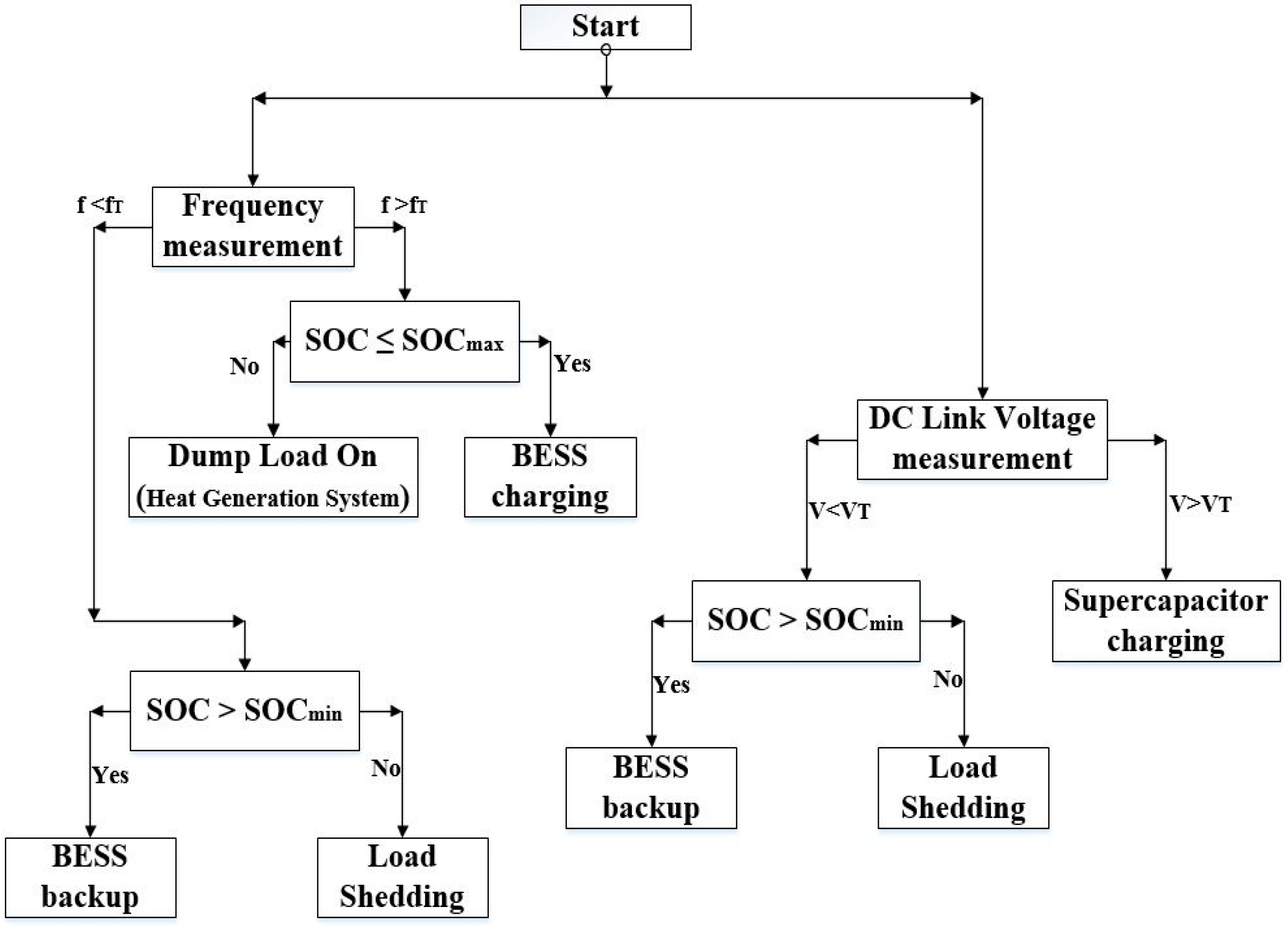
As microgrids operating in standalone mode don’t have a large amount of inertia like utility grids with synchronous rotating machines, renewable power generation or load variations can severely affect the frequency and DC link voltages in a microgrid. The main contribution of this research work is to show that droop control with a diesel generator can be replaced economically by a fuzzy logic and battery storage system to stabilize the system frequency. Droop control is normally used with diesel generators to help change their power references proportionally to frequency deviations from nominal value, but in this case, diesel generator cannot be operated at maximum capacity, whereas in our proposed system, we will supply or consume power causing frequency deviation and system degradation controlled by a fuzzy logic scheme. A flow diagram of the proposed control method is shown in Figure 7.
3.1. Frequency and Voltage Stabilization
In a standalone situation, if the output power of sources cannot satisfy its load demand, the security of the system might be deteriorated. Frequency and voltage stabilization are crucial in distributed generated system-based standalone microgrids. Active and reactive powers are fundamental factors to consider while designing a stable power distribution system. A slight deviation from the maximum active and reactive power limit will induce frequency and voltage stability issues.
Active power consumption is directly related to the frequency of a diesel generator. If the active power shoots beyond the maximum threshold limit, it increases the induced torque within the generator (T = P/w), which means that induced torque exceeds the rotor torque, causes the generator to slow down and decreases its output frequency. The output frequency must stay within permissible limits for safe operation. Similarly, excessive reactive power extraction causes over-excitation in the alternator of a diesel generator and the excitation voltage drops below the rated value which causes a terminal voltage drop. Therefore, various control schemes have been introduced by researchers to overcome these serious issues leading to degradation of the power grid. Droop control is a very common and old technique used in various configurations. The most common technique is master-slave frequency droop where multiple parallel units with the same droop characteristics can respond to falls in frequency by increasing their active power output. Generally, two or more parallel diesel generators are connected as slaves. A master DG controls the slave output power and commands them to provide a predetermined amount of power for frequency stabilization. In this scenario, slave diesel generators work as standby power sources. This droop technique prevents the slaves from providing maximum power, which reduces the overall efficiency because of higher fuel consumption with respect to the output power of diesel generators.
Droop control methods are not competent in renewable energy-based microgrid systems due to their limited power delivery capability. MPPT is an essential process to extract the peak power from renewable sources, whereas, droop control voltage stabilization restricts the system to a limited output power which causes enormous renewable energy losses. Therefore, a supercapacitor-based voltage and frequency stabilization technique is introduced, which offers MPPT with output voltage and frequency stabilization in hybrid standalone microgrids.
The proposed system consists of a supercapacitor-based DC-link voltage stabilizer and battery energy storage system (BESS)-based frequency stabilizer. Supercapacitors are connected is parallel with the DC-link via a DC/DC buck converter to maintain the DC-link voltage within the specified range while the system is operating at MPPT. The DC/DC buck converter is controlled by a standard PID controller, which is responsible for maintaining the DC-link voltage to 500 V DC. Further voltage increase will be consumed and stored in current form in the supercapacitors. Energy stored in supercapacitors is further used to charge the BESS that is attached to the DC link and supercapacitors via s bidirectional DC/DC buck-boost converter. In case, if the BESS is fully charged and the generated power is still more than the load demand, extra generated power will be supplied to the heat generating system used as dump load. This dump load system will keep consuming the extra power to generate heat until the system scenario changes. In general, any dump load system can be selected to meet the requirement, such as a water pump system, heat generating system, etc. The rest of the system works in normal condition until the DC-link voltage stays within the limits. Another case is an overload scenario, where the diesel generator and renewable energy sources fall short of holding the increased load demand either in form of active power or reactive power. As mentioned earlier, any increase in active power directly affects the frequency and causes a frequency drop, while reactive power drops the output voltage. A fuzzy logic-based supervisory controller is designed for voltage and frequency stabilization. If the active power demand is increased, the diesel generator output frequency will keep dropping below its nominal range. In that case, the fuzzy logic-based controller will detect the frequency drop and generate commands to the bidirectional DC/DC buck-boost converter to provide deficit power. Energy stored in the BESS provides the required power to maintain the output frequency. In the reactive power case, the diesel generator output voltage tends to drop, eventually causing the DC-link voltage to drop too. The fuzzy logic-based supervisory controller will sense this disruption and control the BESS system to provide the required power to maintain the DC-link voltage. If the BESS reaches its minimum capacity as discussed in the next section for a loadshedding case, the secondary loads can be disconnected from the main system to avoid overall system degradation and a complete blackout.
3.2. Fuzzy Logic Based Control System
The supervisory controller is a system which supervises different modes of operation and manages the power flow in a system. Furthermore, this master control system also controls the different components functioning mode in order to ensure efficient optimum operation. By using a fuzzy logic-based control system, frequency and voltage stabilization is performed to maintain the power quality, efficiency and reliability of the hybrid standalone microgrid system.
The fuzzy logic technique [33] is used as supervisory controller for the frequency control system in our proposed model. Fuzzy logic is a computing approach based on “degrees of truth” rather than the usual “true or false” (1 or 0) Boolean logic on which modern computers are based. Fuzzy logic seems closer to the way our brains work. We aggregate data and form a number of partial truths which we aggregate further into higher truths which in turn, when certain thresholds are exceeded, cause certain further results such as a motor reaction.
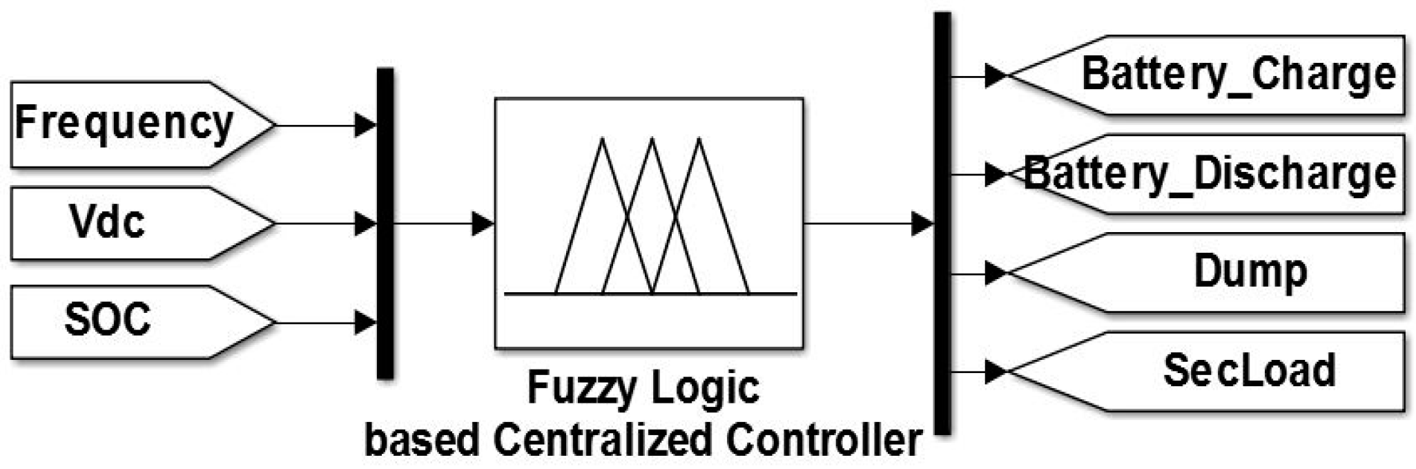
Our proposed fuzzy logic-based frequency and voltage stabilization system controls the battery energy storage system and secondary AC loads based on frequency, voltages and state of charge in case of emergency in a much more efficient, reliable and dynamic way.
It also improves the system response as it doesn’t require any separate process for power and other calculations. Frequency from the PLL block and voltages from the DC link along with battery state of charge are the inputs of the fuzzy-based frequency and voltage controller. The fuzzy logic rules used to maintain the system efficiency can be seen in Table 2. This controller manages the operation of the battery storage system, dump load and secondary loads (load shedding case) as output as shown in Figure 8.
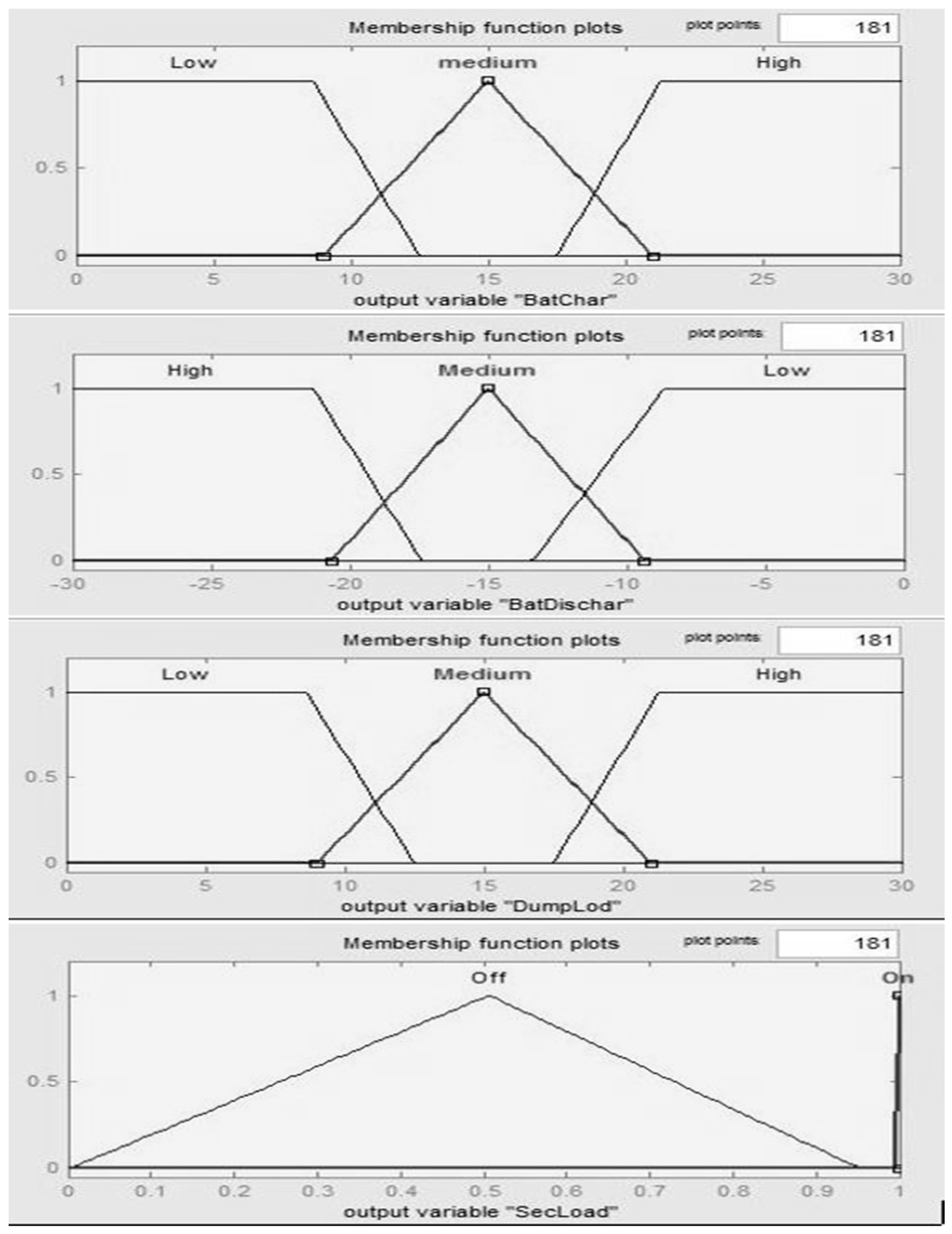
Fuzzy sets can be represented graphically by membership functions. For any set X, a membership function on X is any function X to the real unit interval [0,1]. Membership function on X represent fuzzy subsets. Here, each element of X is mapped to a value between 0 and 1 called degree of membership. There is a high possibility of multiple membership functions for fuzzification of single numeric value. Membership functions for the input and output variables can be seen in Figure 9 and Figure 10. Since the fuzzy system accepts linguistic variables and hence these have to be changed by fuzzification followed by max-min method to set the rules of the controller as expressed by Equation (10), where, α1 and α2 are input variables, μ1 and μ2 are the corresponding membership value:
Similarly, since hybrid microgrid systems cannot respond directly to the fuzzy controls, the fuzzy control output generated by the fuzzy algorithm has to be changed back by using the defuzzification method. Subsequently, the approximate center of gravity (COG) method, which is supposed to be the most accurate method to get an output as crisp value, has been used and is shown in Equation (11):
The weighted average of membership function of the area bounded by its curve is considered as most crisp value of fuzzy quantity. This equation is used to check the strength of rules. Fuzzy logic rules have been developed keeping in mind the practical aspects of system operation. Triangular and trapezoidal membership functions of inputs and outputs are shown in Figure 9 and Figure 10.
Overlapping membership functions are considered to avoid fluctuations and carry out smooth transitions during switching of various controls and shifting between different modes. There are various membership functions for input such as frequency, DC link voltage and SOC whereas output variables are battery charging/discharging control, dump load controller and secondary loads. Fuzzy logic generates output values with respect to input membership functions according to the designed rule base. Operation of the fuzzy logic-based frequency and voltage stabilization system is briefly discussed in Section 4, where it can be seen working in different scenarios according to current conditions.
4. Simulation Studies
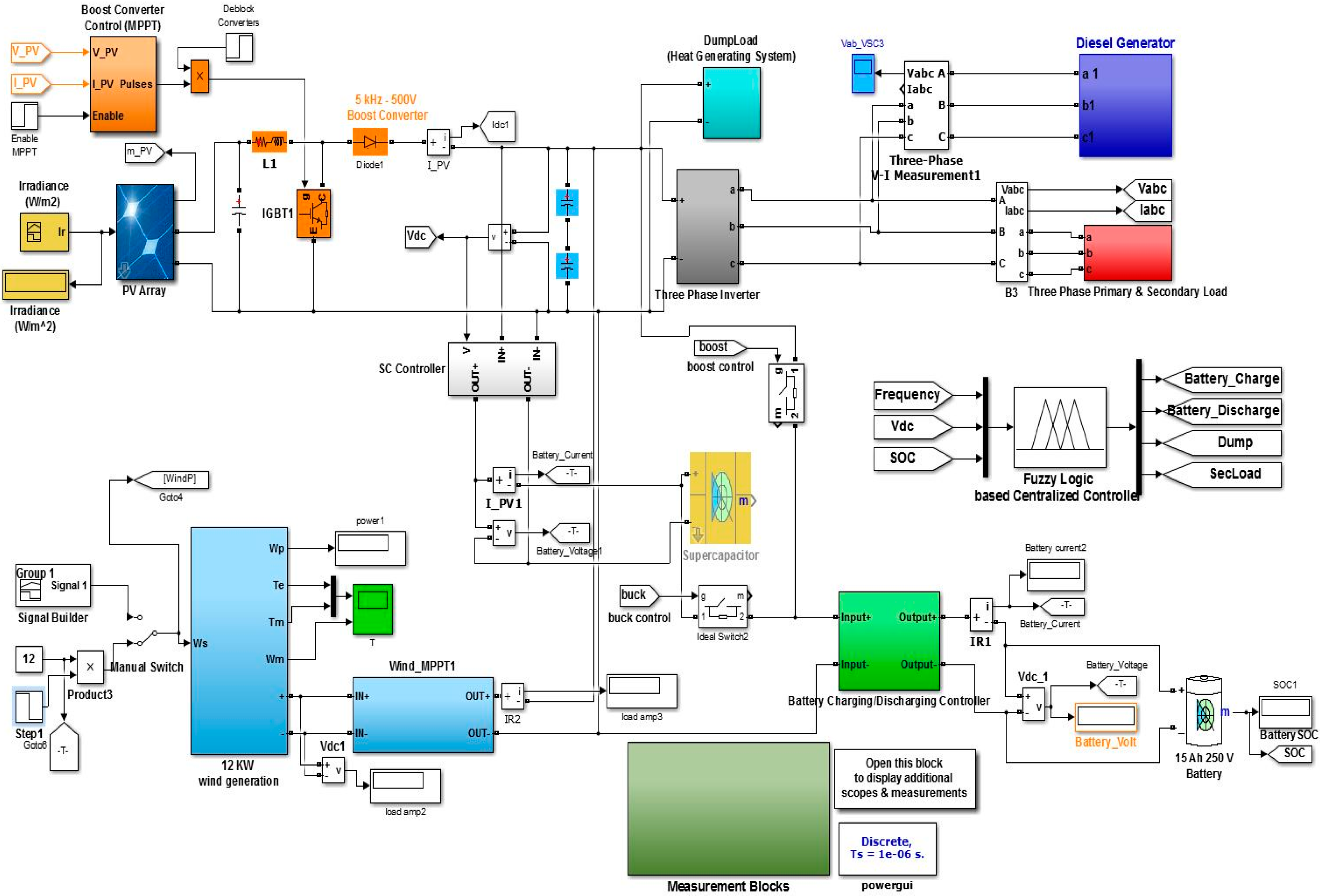
Frequency and voltage stabilization of an AC/DC hybrid standalone microgrid system is briefly described in Section 2 and Section 3. Now the corresponding Matlab/Simulink simulation study is examined in this section. The whole configuration of the proposed system is shown in Figure 11.
The proposed system simulation study is carried out in different scenarios to verify the system performance. The different cases mentioned are the following:
- Frequency and Voltage Stability with Battery Charging and Discharging
- System Overloading (Load Shedding)
These cases are discussed below with the output characteristics of the system response while operating in these specific modes.
4.1. Frequency and Voltage Stabilization with Battery Charging and Discharging
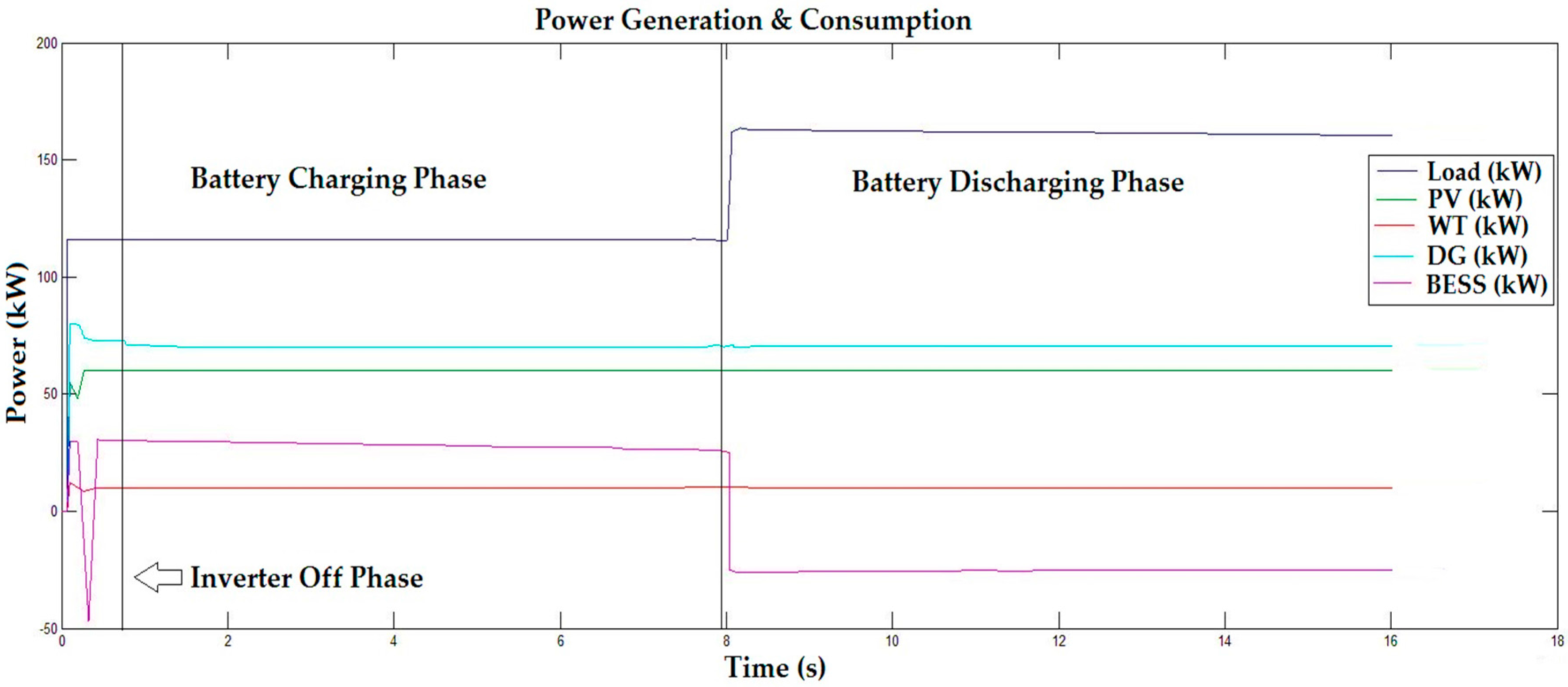
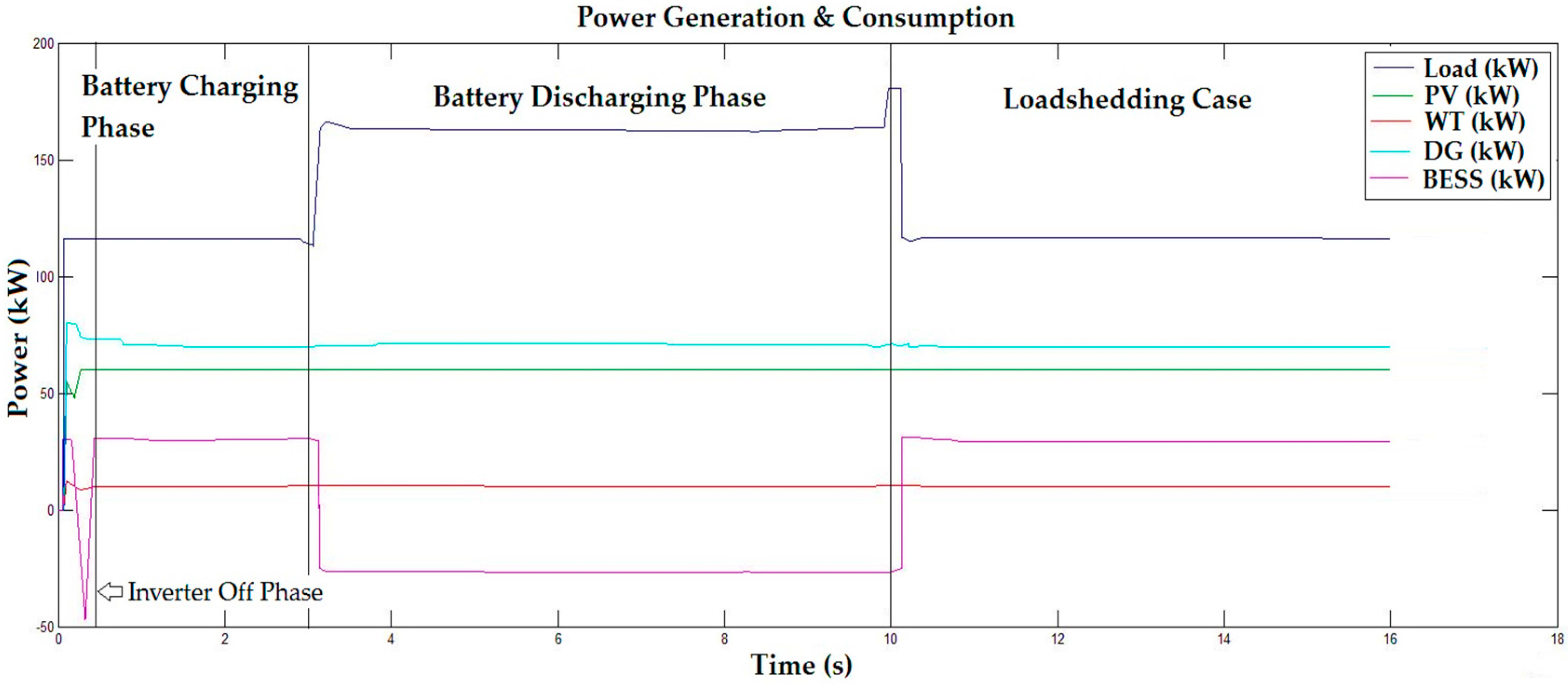
This mode is divided into two parts; i.e., battery charging and battery discharging. Battery charging mode is also the normal mode of operation for our proposed system. Minimum and maximum capacity of the BESS system are 50% and 100%, respectively. Proposed system will work in battery charging mode only if renewable generation system is generating excessive power than load demands and battery system is not charged up to defined level. This will also help to keep microgrid DC link voltage and frequency stabilize. In this situation, the fuzzy logic-based supervisory control system will make the system work in battery charging mode as shown in the first part of Figure 12.
In case, if the load demand is increased or the renewable generation is decreased, it will affect the microgrid frequency or DC link voltages. In that situation, the fuzzy logic-based controller will operate the system in battery discharging mode to avoid frequency or voltage destabilization and bring it back to the normal value as shown in the second part of Figure 12.
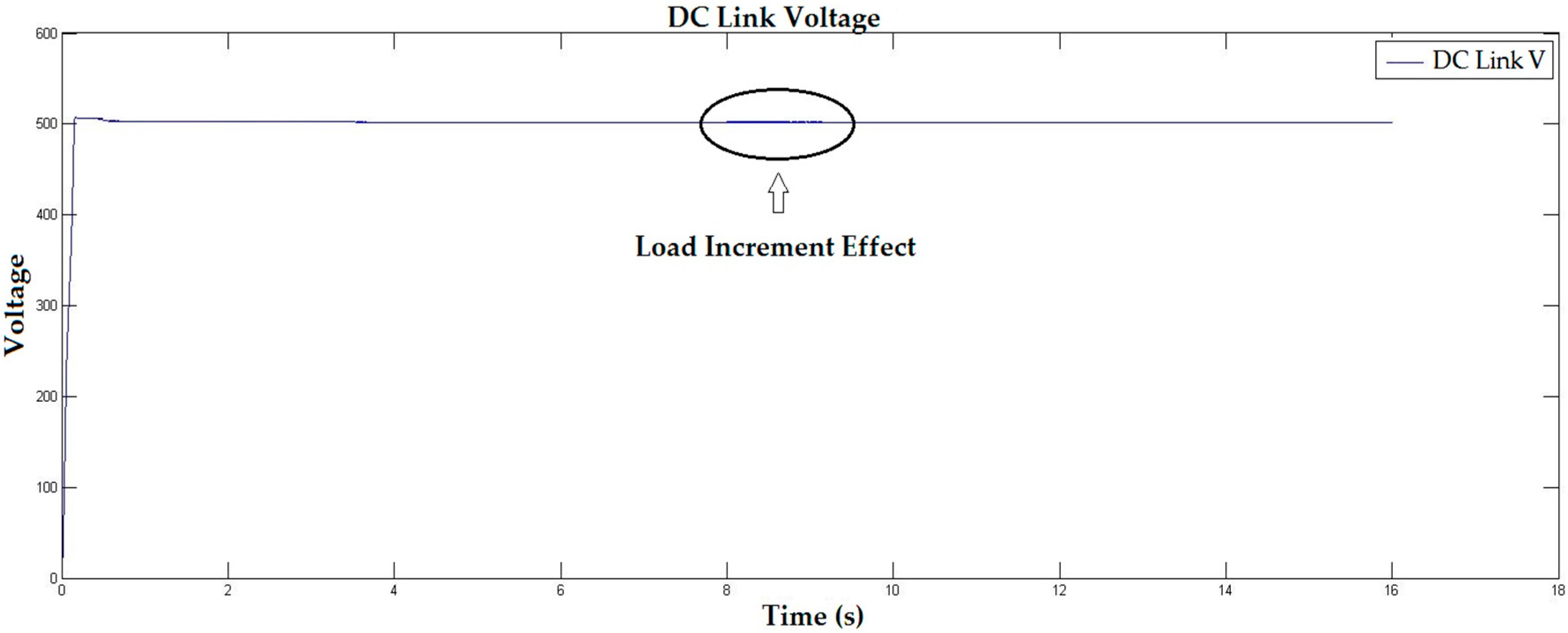
Also the effect of load increment and proposed system efficient response can be seen in the case of DC link voltage and frequency in Figure 13 and Figure 14, respectively.
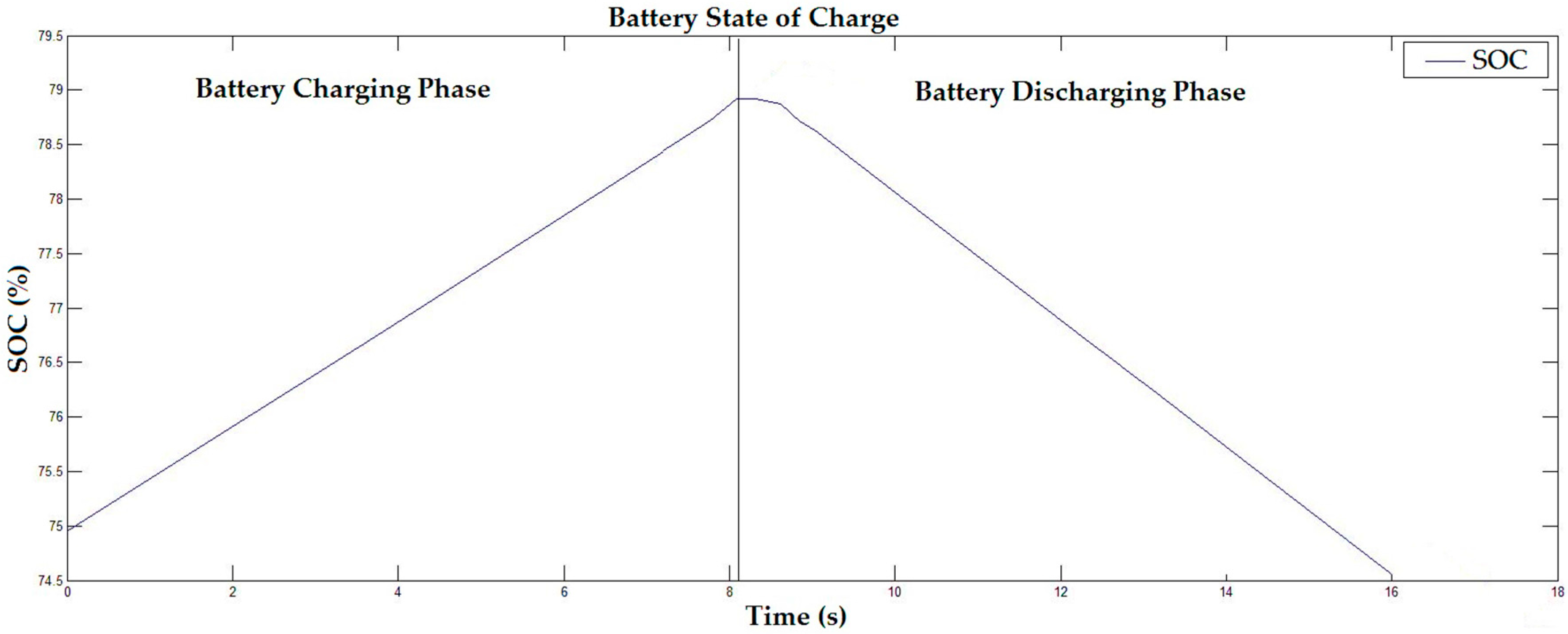
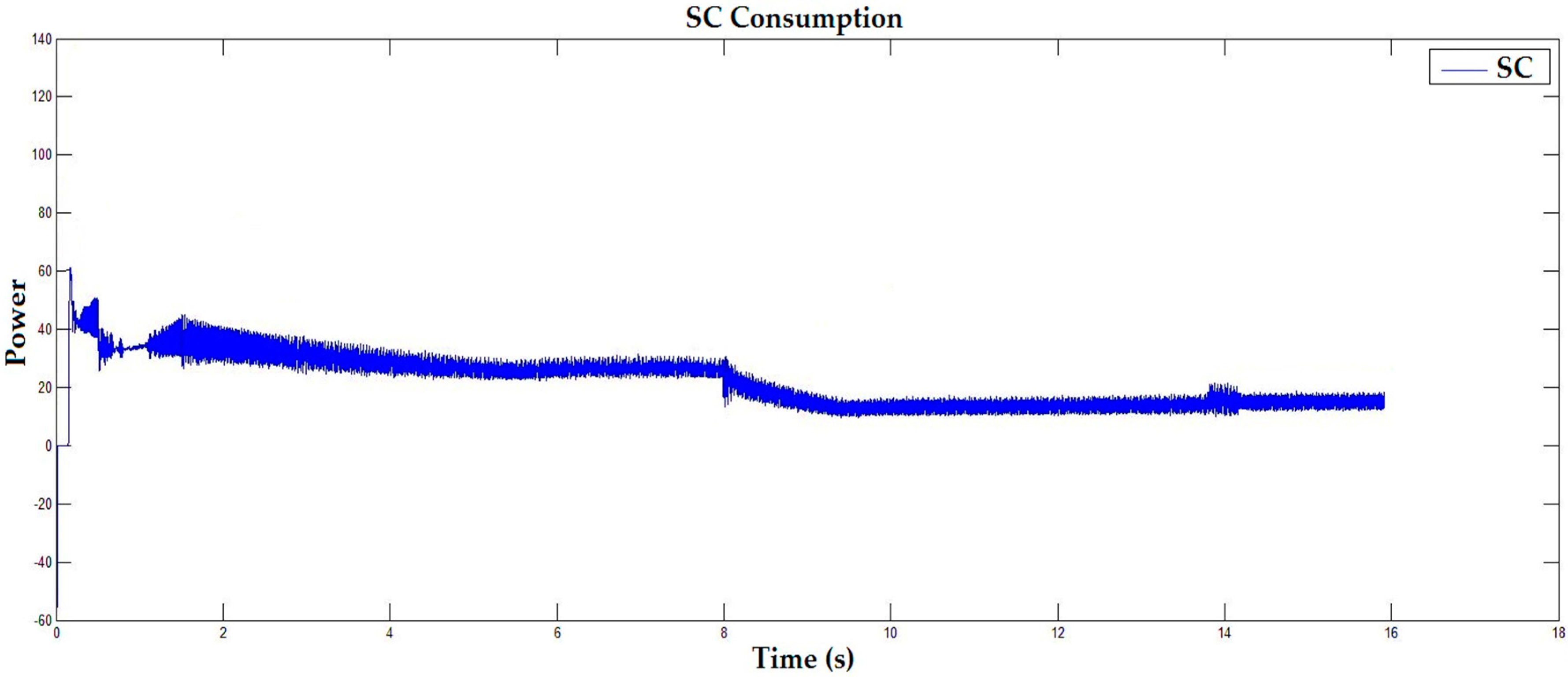
It can be seen that as soon as the frequency drops below the standard value of 60 Hz, the fuzzy controller enables the battery backup system to supply the deficit power to maintain the frequency and system stability. As shown, the frequency is stabilized at 60 Hz again in short time span, even keeping the deviation between the permissible limit of (±0.5). The battery SOC and supercapacitor power consumption can also be seen in Figure 15 and Figure 16.
4.2. System Overloading (Load Shedding)
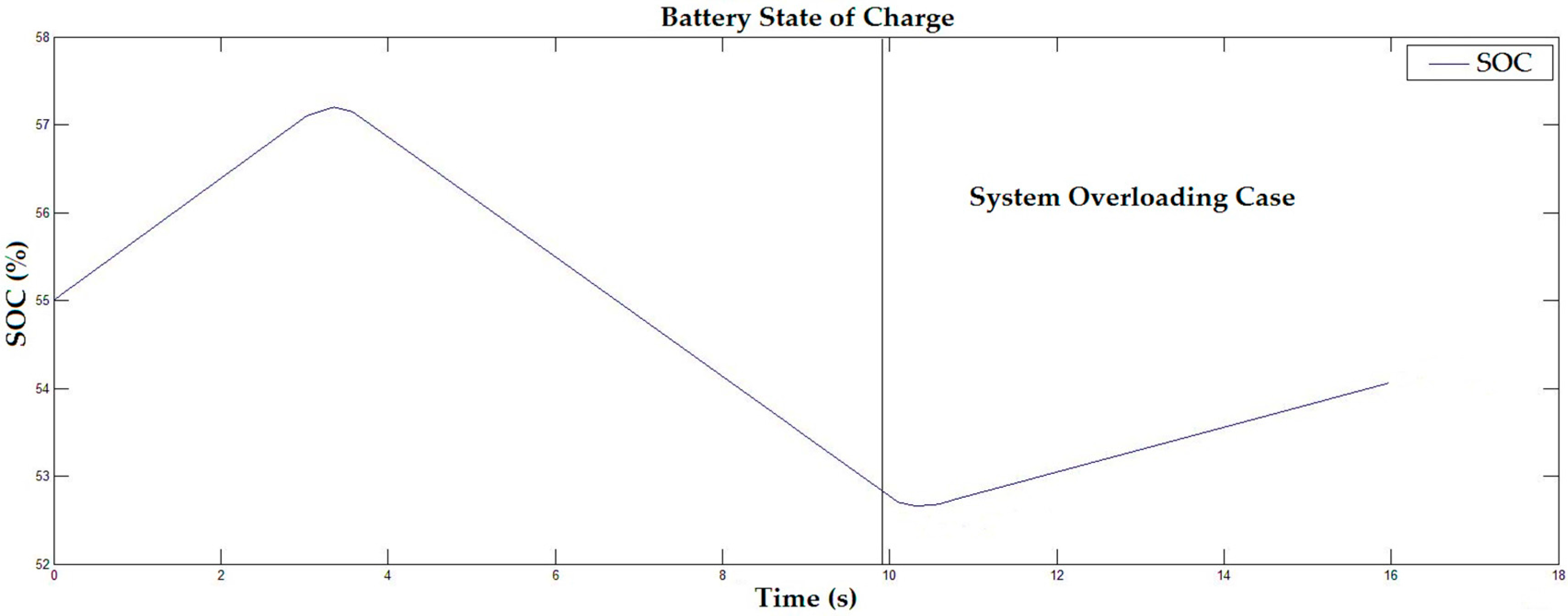
Keeping in mind the limited capacity of a BESS, a load shedding scenario is considered in the proposed system to avoid microgrid degradation and in severe cases, system collapse. In this case, if the battery SOC reaches to its minimum level during discharging mode to maintain frequency and voltage or load increases beyond the capacity of the microgrid system current generation, the fuzzy logic-based system will cut off the flexible secondary loads to maintain system frequency and avoid a complete blackout. The hybrid system output response in this case can be seen in the third part of Figure 17. At that point, load increases more than the generated power and battery SOC is at its minimum level, which activates the overloading mode and flexible secondary loads are cut off from the main load. As the generated power increases more than the AC load after cutting the flexible secondary loads, the battery system will start charging again. The effect on frequency and voltage can be seen in Figure 18 and Figure 19, respectively. Battery SOC can also be seen in Figure 20.
As we can see in Figure 18 and Figure 19, frequency and voltage increase from their nominal value due to the cutting off of the flexible load. This happens because the generated power is increased as mentioned above, and the BESS will start charging to bring back them to the standard value. Figure 20 also shows that when the fuzzy logic-based controller switches system operation to load shedding mode, the battery starts charging as reduce the load due to cutting off the flexible secondary loads. Flexible secondary loads will connect again to the system as soon as the renewable generation increases.
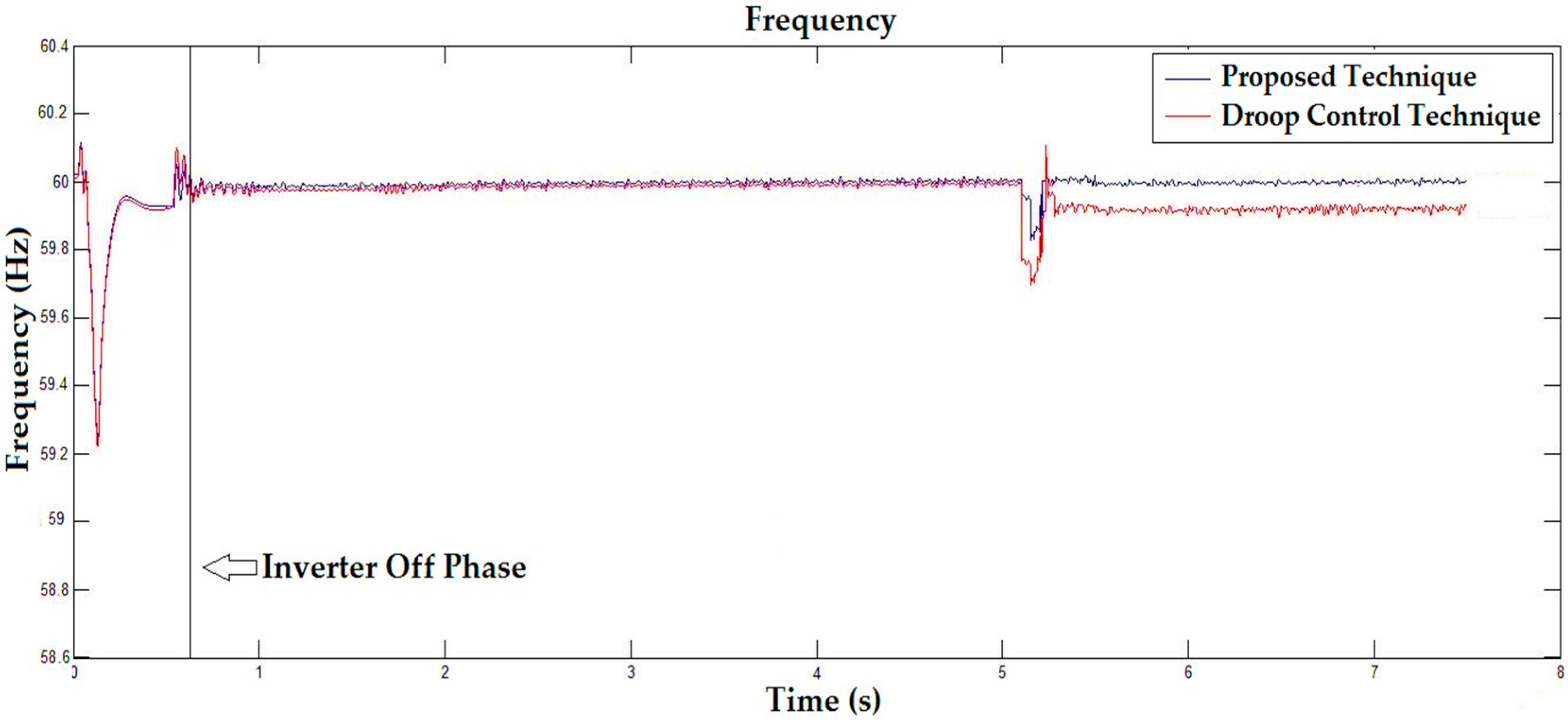
From Figure 21, one can notice that the system frequency restoration and settling around the nominal frequency is much better with the proposed control technique as compared to the previously used droop control technique, as it can be seen that the frequency using the proposed controller settled at almost 60 Hz, whereas using droop control, after high fluctuations it stabilizes on 59.84 Hz approximately.
5. Conclusions
In this research work, an efficient and reliable strategy for frequency and voltage stabilization of a standalone hybrid microgrid is presented. This study aims to solve the problem of stable operation of standalone microgrids, especially concerning the frequency and voltage stability. A BESS is used to stabilize the frequency and voltage in emergency cases. The rapid response of the BESS results in the frequency being maintained at a standard value and kept within permissible limits, even when it deviates. Furthermore, a supercapacitor is introduced to keep the DC bus voltage stabilized even though MPPT is used to extract the maximum possible power from renewable resources. Finally, a fuzzy logic supervisory controller based on 21 rules has demonstrated its advantages by ensuring a smart power management system, even when the system faces load-shedding scenarios.
Acknowledgments
This work (Grants No. C0268141) was supported by Business for Academic-industrial Cooperative establishments funded Korea Small and Medium Business Administration in 2015.
Author Contributions
Furqan Asghar surveyed the background of this research, designed the hybrid system with control strategy, performed Matlab simulations and wrote the paper. Muhammad Talha reviewed the paper to add his thoughts for manuscript improvement and then revised manuscript for proofreading. Sung Ho Kim supervised and support this research study.
Conflicts of Interest
The authors declare no conflict of interest.
Nomenclature
| PLoad | Total Load Power |
| PDG | Diesel Generator Power |
| PWT | Wind Turbine Power |
| PPV | Photovoltaic Power |
| PBESS | Battery Energy Storage System Power |
| PPVModule | Single PV Module Power |
| VMMP | Module Voltage at Maximum Power Point |
| IMPP | Module Current at Maximum Power Point |
| NT | Total Number of Modules |
| Ns, Np | Number of Modules in Series and Parallel |
| Vnominal | Rated Voltage |
| SPVA | Photovoltaic Single Module Area |
| ρ | Air Density |
| Vω | Wind Speed |
| A | Rotor Swept Area |
| Cp | Maximum Power Coefficient for Wind Turbine Power |
| Cbattery | Battery Total Capacity |
| Ebattery | Power Supplied by Battery |
| Vbattery | Battery Voltages |
| T | Time |
| α1, α2 | Fuzzy Input Variables |
| μ1, μ2 | Corresponding Membership Values |
| COG | Center of Gravity |
References
- Ou, T.C.; Tsao, T.P.; Lin, W.M.; Hong, C.M.; Lu, K.H.; Tu, C.S. A Novel Power Flow Analysis for Microgrid Distribution System. In Proceedings of the 2013 8th IEEE Conference on Industrial Electronics and Applications (ICIEA), Melbourne, Australia, 19–21 June 2013; pp. 1550–1555. [Google Scholar]
- Thresher, R.; Robinson, M.; Veers, P. To Capture the Wind. IEEE Power Energy Mag. 2007, 5, 34–46. [Google Scholar] [CrossRef]
- Moradi, H.; Abtahi, A.; Esfahanian, M. Optimal Operation of a Multi-Source Microgrid to Achieve Cost and Emission Targets. In Proceedings of the 2016 IEEE Power and Energy Conference at Illinois (PECI), Urbana, IL, USA, 19–20 February 2016. [Google Scholar]
- Wang, H.; Huang, J. Joint Investment and Operation of Microgrid. IEEE Trans. Smart Grid 2017, 8, 833–845. [Google Scholar] [CrossRef]
- Boroojeni, K.; Amini, M.H.; Nejadpak, A.; Dragicevic, T.; Iyengar, S.S.; Blaabjerg, F. A Novel Cloud-Based Platform for Implementation of Oblivious Power Routing for Clusters of Microgrids. IEEE Access 2016, 5, 607–619. [Google Scholar] [CrossRef]
- Boroojeni, K.G.; Amini, M.H.; Nejadpak, A.; Iyengar, S.S.; Hoseinzadeh, B.; Bak, C.L. A Theoretical Bilevel Control Scheme for Power Networks with Large-Scale Penetration of Distributed Renewable Resources. In Proceedings of the 2016 IEEE International Conference on Electro Information Technology (EIT), Grand Forks, ND, USA, 19–21 May 2016; pp. 0510–0515. [Google Scholar]
- Al-Saedi, W.; Lachowicz, W.; Habibi, D.; Bass, O. Power Quality Enhancement in Autonomous Microgrid Operation using Particle Swarm Optimization. Int. J. Elect. Power Energy Syst. 2012, 42, 139–149. [Google Scholar] [CrossRef]
- Dekker, J.; Nthontho, M.; Chowdhury, S.; Chowdhury, S.P. Economic Analysis of PV/Diesel Hybrid Power Systems in Different Climatic Zones of South Africa. Int. J. Elect. Power Energy Syst. 2012, 40, 104–112. [Google Scholar] [CrossRef]
- Kamalapur, G.D.; Udaykumar, R.Y. Rural Electrification in India and Feasibility of Photovoltaic Solar Home Systems. Int. J. Elect. Power Energy Syst. 2011, 33, 594–599. [Google Scholar] [CrossRef]
- Ministry of Trade, Industry and Energy. 2014 Business Planning Report; Ministry of Trade, Industry and Energy: Sejong, Korea, February 2014. [Google Scholar]
- Unamuno, E.; Barrena, J.A. Equivalence of Primary Control Strategies for AC and DC Microgrids. Energies 2017, 10, 1. [Google Scholar] [CrossRef]
- Ou, T.-C.; Hong, C.-M. Dynamic Operation and Control of Microgrid Hybrid Power Systems. Energy 2014, 66, 314–323. [Google Scholar] [CrossRef]
- Xin, H.; Liu, Y.; Wang, Z.; Gan, D.; Yang, T. A New Frequency Regulation Strategy for Photovoltaic Systems without Energy Storage. IEEE Trans. Sustain. Energy 2013, 4, 985–993. [Google Scholar] [CrossRef]
- Chang-Chein, L.R.; Yin, Y.C. Strategies for Operating Wind Power in Similar Manner of Conventional Power Plant. IEEE Trans. Energy Convers. 2009, 24, 926–934. [Google Scholar] [CrossRef]
- Sao, C.; Lehn, P.W. Autonomous Load Sharing between Converters and Generators in Microgrids. In Proceedings of the 2011 IEEE Power Energy Society General Meeting, Detroit, MI, USA, 24–29 July 2011; pp. 1–8. [Google Scholar]
- Kahrobaeian, A.; Ibrahim Mohammed, Y.A.R. Network Based Hybrid Distributed Power Sharing and Control for Islanded Microgrid Systems. IEEE Trans. Power Electron. 2015, 30, 603–617. [Google Scholar] [CrossRef]
- Hu, J.; Zhu, J.; Dorrell, D.G.; Guerrero, J.M. Virtual Flux Droop Method- A New Control Strategy of Inverters in Microgrid. IEEE Trans. Power Electron. 2014, 29, 4704–4711. [Google Scholar] [CrossRef]
- Vandoorn, T.L.; Meersman, B.; Kooning, J.D.M.D.; Vandevelde, L. Directly Coupled Synchronous Generators with Converter Behavior in Islanded Microgrids. IEEE Trans. Power Syst. 2012, 27, 1395–1406. [Google Scholar] [CrossRef]
- De Matos, J.G.; Silva, F.S.F.E.; Ribeiro, L.A.S. Power Control in AC Isolated Microgrids with Renewable Energy Sources and Energy Storage Systems. IEEE Trans. Ind. Electron. 2015, 62, 3490–3498. [Google Scholar]
- Wu, D.; Tang, F.; Dragicevic, T.; Vasquez, J.C.; Guerrero, J.M. A Control Architecture to Coordinate Renewable Energy Sources and Energy Storage Systems in Isolated Microgrids. IEEE Trans. Smart Grid 2015, 6, 1156–1166. [Google Scholar] [CrossRef]
- Fadoul, S.T.; Hamadi, A.; Chandra, A.; Ndtoungou, A. Optimization of Standalone Microgrid Considering Active Damping Technique and Smart Power Management using Fuzzy Logic Supervisor. IEEE Trans. Smart Grid 2017, 8, 475–484. [Google Scholar]
- Muljadi, E.; Wang, C.; Nehrir, M.H. Parallel operation of wind turbine, fuel cell, and diesel generation sources. In Proceedings of the 2004 IEEE Power Engineering Society General Meeting, Denver, CO, USA, 6–10 June 2004; pp. 1927–1932. [Google Scholar]
- Bawaney, P.; Sridhar, B. Power Distribution of Wind Diesel Generator in Isolated Network. Int. J. Sci. Eng. Res. 2012, 3, 364–369. [Google Scholar]
- Moradi, H.; Abtahi, A.; Messenger, R. Annual Performance Comparison between Tracking and Fixed Photovoltaic Arrays. In Proceedings of the 2016 IEEE 43rd Photovoltaic Specialists Conference Plenary Speakers, Portland, OR, USA, 5–10 June 2016; pp. 3179–3183. [Google Scholar]
- Choudhary, D.; Saxena, A.R. Incremental Conductance MPPT Algorithm for PV System Implemented using DC-DC Buck and Boost Converter. Int. J. Eng. Res. Appl. 2014, 14, 123–132. [Google Scholar]
- Hong, C.M.; Ou, T.C.; Lu, K.H. Development of Intelligent MPPT (maximum power point tracking) Control for a Grid-Connected Hybrid Power Generation System. Energy 2013, 50, 270–279. [Google Scholar] [CrossRef]
- Saravana, S.D. Modeling and Simulation of Incremental Conductance MPPT Algorithm for Photovoltaic Applications. Int. J. Sci. Eng. Technol. 2013, 2, 681–685. [Google Scholar]
- Kumar, S.S.; Jayanthi, K.; Kumar, N.S. Maximum Power Point Tracking for a PMSG based Variable Speed Wind Energy Conversion System using Optimal Torque Control. In Proceedings of the International Conference on Advanced Communication Control and Computing Technologies, Ramanathapuram, India, 25–27 May 2016; pp. 347–352. [Google Scholar]
- Cihak, T.; Jakopovic, Z. Supercapacitors in Power Converter DC Link. In Proceedings of the 34th International Convention Mipro 2011, Opatija, Hrvatska, 23–27 May 2011. [Google Scholar]
- Stott, P.A.; Mueller, M.A. Modelling Fully Variable Speed Hybrid Wind Diesel Systems. In Proceedings of the 41st International Universities Power Engineering Conference, Newcastle-upon-Tyne, UK, 6–8 September 2006; pp. 212–216. [Google Scholar]
- Asghar, F.; Kim, S.-Y.; Kim, S.H. Development of Heat Generating System based on Small Wind Turbine System. In Proceedings of the 2014 Joint 7th International Conference on and Advanced Intelligent Systems (ISIS), Kitakyushu, Japan, 3–6 December 2014; pp. 1209–1212. [Google Scholar]
- Moradi, H.; Abtahi, A.; Esfahanian, M. Optimal Energy Management of a Smart Residential Combined Heat, Cooling and Power. Int. J. Technol. Phys. Probl. Eng. 2016, 8, 9–16. [Google Scholar]
- Bisht, M.S. Fuzzy Logic based Intelligent Control Strategy in Standalone Hybrid AC Microgrid. In Proceedings of the 2014 IEEE Conference on Control Applications, Juan Les Antibes, France, 8–10 October 2014; pp. 873–878. [Google Scholar]
Figure 1.
Proposed hybrid microgrid with fuzzy-based frequency and voltage controller.
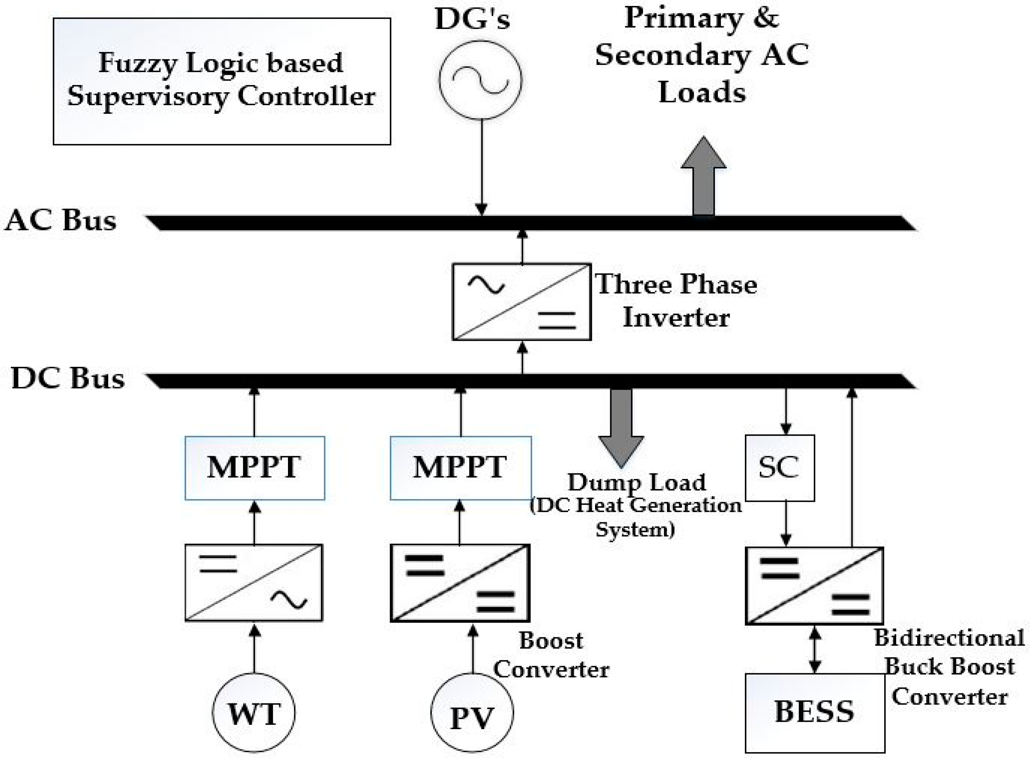
Figure 2.
Governor control of the diesel generator.

Figure 3.
Governor control of a wind turbine.

Figure 4.
Wind turbine reference current curve.

Figure 5.
Battery charging and discharging controller.

Figure 6.
Internal configuration of the dump load controller.

Figure 7.
Flowchart of the proposed control method.

Figure 8.
Fuzzy logic-based frequency and voltage control system.

Figure 9.
Membership functions for input variables.
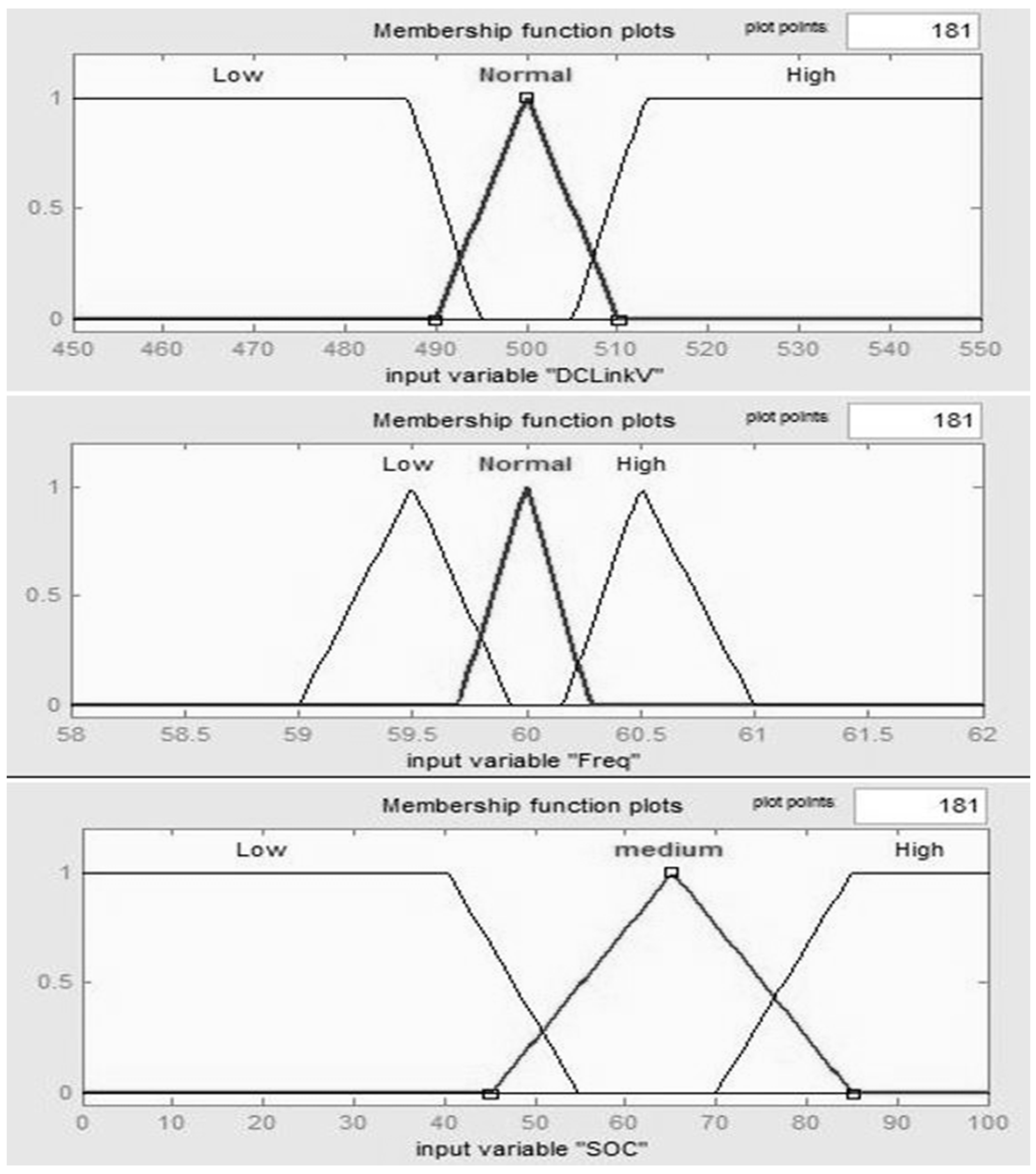
Figure 10.
Membership functions for output variables.

Figure 11.
Proposed system Simulink diagram.

Figure 12.
System output characteristics in battery charging and discharging mode.

Figure 13.
Load effect on DC link voltages.

Figure 14.
Frequency response in battery charging and discharging mode.
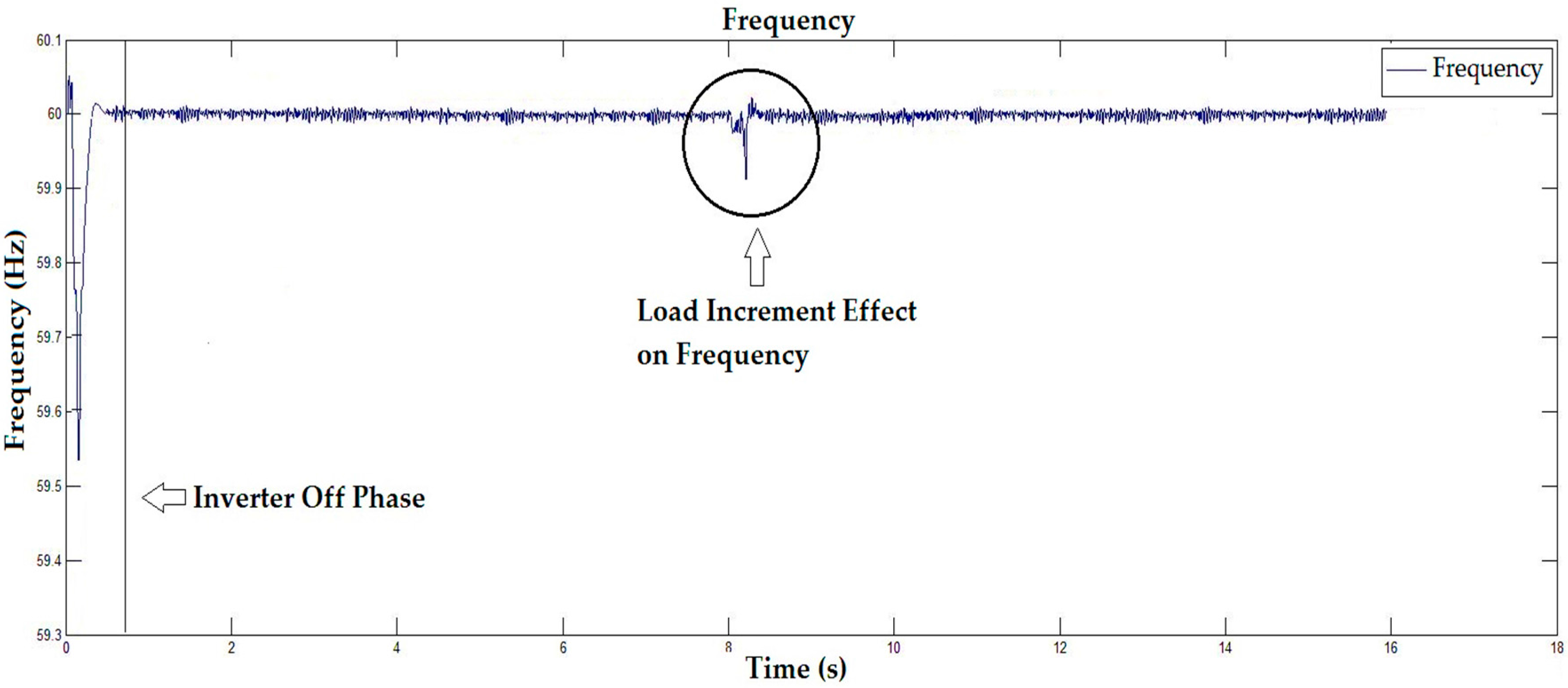
Figure 15.
Battery SOC in battery charging and discharging mode.

Figure 16.
Supercapacitor power consumption.

Figure 17.
System output characteristics in system overloading mode (load shedding).

Figure 18.
Frequency response in system overloading mode.
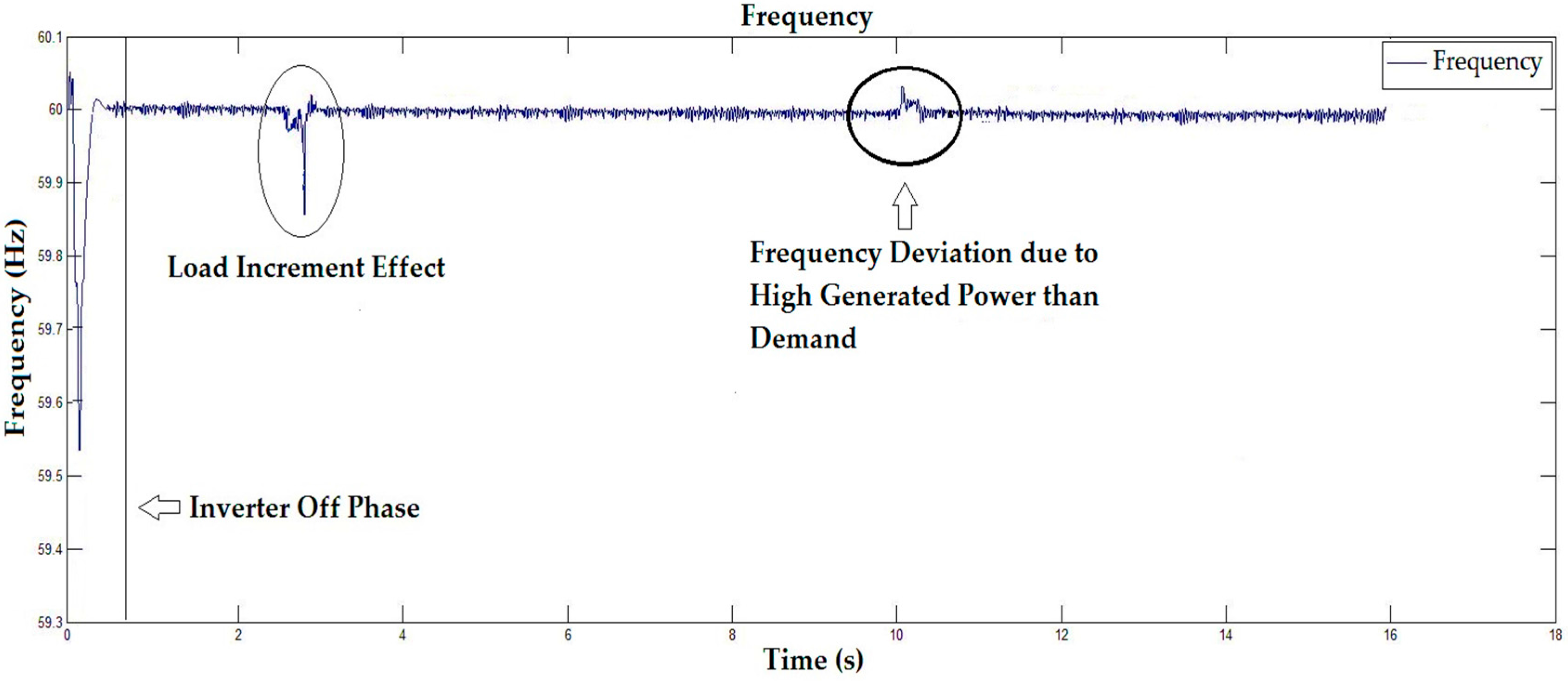
Figure 19.
DC link voltage response in system overloading mode.
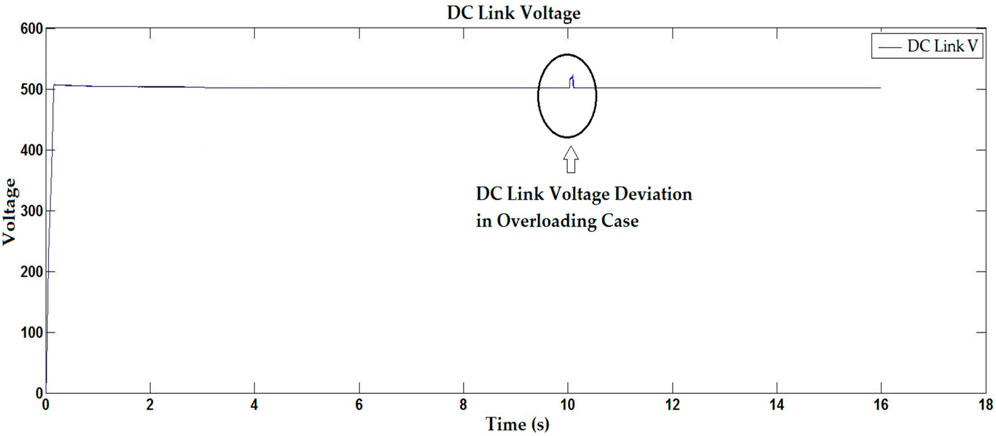
Figure 20.
Battery SOC in system overloading mode.

Figure 21.
Frequency response comparison of between proposed control system and conventional droop control method.
Figure 21.
Frequency response comparison of between proposed control system and conventional droop control method.


Table 1.
Designed microgrid system configuration.
| Input Date & Parameters | Value | Unit |
|---|---|---|
| PDG | 70 | kW |
| PPV | 60 | kW |
| PWT | 10 | kW |
| Lprimary | 116 | kW |
| Lsecondary | 45,20 | kW |
| Nominal Frequency | 60 | Hz |
| DC Link Voltage | 500 | V |
| SOCmin | 50 | % |
| SOCmax | 100 | % |
| Sample time_Control | 1 × 10⁻⁶ | s |
Table 2.
Fuzzy logic rules.
| Fuzzy | Fuzzy Input | Fuzzy Output | |||||
|---|---|---|---|---|---|---|---|
| Rules | Frequency | DC Link Voltage | DOC | Battery Charging | Battery Discharging | Dump Load (Heating System) | Secondary Loads |
| 1 | L | L | L | Z | Z | OFF | OFF |
| 2 | L | L | M | Z | H | OFF | ON |
| 3 | L | L | H | Z | H | OFF | ON |
| 4 | L | N | L | Z | Z | OFF | OFF |
| 5 | L | N | M | Z | H | OFF | ON |
| 6 | L | N | H | Z | H | OFF | ON |
| 7 | N | L | L | Z | Z | OFF | OFF |
| 8 | N | L | M | Z | H | OFF | ON |
| 9 | N | L | H | Z | H | OFF | ON |
| 10 | N | N | L | H | Z | OFF | OFF |
| 11 | N | N | M | Z | M | OFF | ON |
| 12 | N | N | H | Z | H | OFF | ON |
| 13 | N | H | L | H | Z | OFF | ON |
| 14 | N | H | M | H | Z | L | ON |
| 15 | N | H | H | L | Z | H | ON |
| 16 | H | N | L | H | Z | OFF | ON |
| 17 | H | N | M | H | Z | M | ON |
| 18 | H | N | H | L | Z | H | ON |
| 19 | H | H | L | H | Z | L | ON |
| 20 | H | H | M | H | Z | M | ON |
| 21 | H | H | H | L | Z | H | ON |
N = Normal, L = Low, H = High, M = Medium, Z = Zero.
© 2017 by the authors. Licensee MDPI, Basel, Switzerland. This article is an open access article distributed under the terms and conditions of the Creative Commons Attribution (CC BY) license (http://creativecommons.org/licenses/by/4.0/).
Share and Cite
MDPI and ACS Style
Asghar, F.; Talha, M.; Kim, S.H. Robust Frequency and Voltage Stability Control Strategy for Standalone AC/DC Hybrid Microgrid. Energies 2017, 10, 760. https://doi.org/10.3390/en10060760
AMA Style
Asghar F, Talha M, Kim SH. Robust Frequency and Voltage Stability Control Strategy for Standalone AC/DC Hybrid Microgrid. Energies. 2017; 10(6):760. https://doi.org/10.3390/en10060760
Chicago/Turabian StyleAsghar, Furqan, Muhammad Talha, and Sung Ho Kim. 2017. "Robust Frequency and Voltage Stability Control Strategy for Standalone AC/DC Hybrid Microgrid" Energies 10, no. 6: 760. https://doi.org/10.3390/en10060760
Note that from the first issue of 2016, this journal uses article numbers instead of page numbers. See further details here.