
Experimental Study on the Influence of the Rotating Cylinder Block and Pistons on Churning Losses in Axial Piston Pumps


1
State Key Laboratory of Fluid Power and Mechatronic Systems, Zhejiang University, Zheda Road 38, Hangzhou 310027, China
2
Department of Mechanical Engineering, University of Bath, Bath BA2 7AY, UK
*
Author to whom correspondence should be addressed.
Energies 2017, 10(5), 662; https://doi.org/10.3390/en10050662
Submission received: 20 March 2017
/
Revised: 28 April 2017
/
Accepted: 8 May 2017
/
Published: 10 May 2017
(This article belongs to the Special Issue Energy Efficiency and Controllability of Fluid Power Systems)
Abstract
:Pressure and performance requirements of axial piston pumps and the proportion of churning losses in axial piston pumps increase significantly with increasing speed. To investigate the primary distribution of churning losses in axial piston pumps at various ranges of speed, a test rig was set up in which other friction losses can be eliminated, thus making it possible to investigate the net churning losses in an axial piston pump. The influence of the rotating cylinder block and pistons on churning losses is analyzed based on a qualitative evaluation of the various fluid flow regimes at different test speeds in an axial piston pump. The analytical results indicate that pistons have less influence on churning losses than the rotating cylinder block beyond the critical speed in axial piston pumps, because the total energy dissipation transforms laminar viscous friction losses into turbulent shear stress losses. It is concluded that more attention should be given to the effect of the rotating cylinder block on churning losses in axial piston pumps at high rotation speed.
1. Introduction
Axial piston pumps are widely used in fluid power systems for advantages such as high power-mass ratio, high limit load pressure and high overall efficiency [1,2,3]. Figure 1 illustrates the general configuration of a conventional axial piston pump consisting of several pistons mounted within the cylinder bores at equal angular intervals around the centerline of the cylinder block. The piston heads are mounted in the slippers under the action of the retainer mechanism. Since a swash plate limits the displacement of pistons, the pistons reciprocate in the cylinder bores suctioning and discharging oil through a valve plate which is fixed to the pump casing.
However, pump efficiency is relatively low with the increase of operating parameters because of increasing power losses [4,5]. According to [6,7,8,9], energy losses can be classified into three groups in the axial piston pumps. The first group is volumetric losses caused by leakage flow losses, the losses in the second group are mechanical losses due to friction losses, and the third group is churning losses caused by the internal rotating components stirring the hydraulic fluid in axial piston pumps. Theoretical and experimental studies have been published on volumetric losses and mechanical losses in axial piston pumps [10,11,12,13,14,15].
Wilson [10] firstly established the mathematical models of volumetric and mechanical losses in the conditions of laminar and turbulent flow in axial piston pumps. The leakage equations and the viscous torque losses were considered in his mathematical model. Ivantysynova and Lasaar [11] developed a non-isothermal gap flow model to predict the leakage, pressure distribution and temperature of all lubricating gaps in swash plate type axial piston machines. They integrated the Reynolds equation of lubrication, solved numerically for the connected gaps of swash plate axial piston machines. Manring et al. [12,13] carried out experimental and theoretical studies of mechanical losses based on the Stribeck curve in an axial piston pump. They derived the power loss and efficiency of a pump which related to the compressibility losses of the fluid. Bergada et al. [14] developed new algebraic leakage equations of all piston pump gaps and tested against numerical models. The effect of different leakages through pump clearances was investigated, and the main source of the leakage in piston pumps was demonstrated by means of the algebraic leakage equations in their simulation model. Xu et al. [15] explored the variation characteristics of volumetric losses of axial piston pumps over a wide operating range theoretically and experimentally, in particular for the displacement conditions. The proposed novel volumetric losses model can give a clear insight into the components of leakage.
However, there are only a few studies published on churning losses in axial piston pumps. The churning loss is usually neglected because its effect is minor for pumps with nominal speeds of 1500–3000 rpm. With increasing speed, the proportion of churning losses in axial piston pumps gradually increases, especially for pumps applied in aeronautics and astronautics due to the need for high power/weight ratio. Taking the high-speed axial piston pump of Messier-Bugatti implemented in airplane A380 as an example, the nominal speed is more than 15,000 rpm [16]. Also, the similar piston pumps of Parker [17] provided for F-35 can even be operated at rotation speed up to 20,000 rpm. The churning losses cannot be ignored when the axial piston pumps rotate at such high speed because of large centrifugal forces of piston/cylinder assemblies and high kinetic fluid energy, which can result in aggravated churning losses. The earliest report was made by Jang in 1997 [18], who first proposed the concept of churning losses in axial piston pumps. After that, Håkan [19] carried out experimental studies of churning losses and concluded that the churning loss was significant under low pressure operating conditions in axial piston pumps. They estimated that the proportion of churning losses was approximately 20% of total losses. In recent years, Ivantysynova et al. [20,21] developed the mathematical models of churning losses with the assumption of laminar flow in axial piston pumps. The churning loss was considered in their simulation model, and the temperature effects in the casing and outlet port of axial piston machines under steady state operation were examined.
A review of previous research [18,19,20,21] has been devoted to the churning losses in axial piston pumps, whereas these studies have typically focused on the models for calculating total churning power losses. Little information is available on the rotating cylinder and pistons effect on churning losses respectively, especially in high-speed conditions. Conventional theoretical and experimental analyses are commonly based on the assumption that the flow is laminar. This assumption may be practical at low rotation speeds; but when the pump attempts to operate at high rotation speeds, problems will arise and the turbulence phenomenon in the oil-filled casing will become more evident.
Despite the fact that churning losses about the turbulence have no evidence in high rotation speed axial piston pumps, there are some detailed researches in external gear machines and geared transmissions. Thiagarajan and Vacca [22,23] presented the expression for the different sources of torque losses, which took into account turbulence resistance in external gear machines. The torque losses expression was subsequently integrated into an entirely mathematical equation to evaluate the viscous friction losses in external gear machines. Changenet et al. [24] investigated the various fluid flow regimes characterized by Reynolds numbers; the production of churning loss was dominated by centrifugal effects under high-speed and high-temperature tests in geared transmissions. The contributions of gear machines play an important role in guiding the study of axial piston pumps.
The aim of this paper is to analyze the effects of the rotating cylinder block and pistons on churning losses in axial piston pumps at high rotation speeds. The proportion of the rotating cylinder block and pistons on churning losses is measured experimentally. The measured results will contribute to a targeted support for reducing churning losses and more comprehensive theoretical models for the rotating cylinder block and pistons.
2. Mathematical Analysis
Figure 2 shows the schematic representation of churning losses in axial piston pumps. It can be seen in Figure 1 and Figure 2 that the churning losses of axial piston pumps are caused by the rotation of the cylinder block together and the circling motion of the pistons in the casing filled with hydraulic fluid.
A mathematical model of churning losses due to the rotation of the cylinder block was presented under the assumption of laminar flow in axial piston pumps. The viscous friction Fv for the steady laminar motion of incompressible Newtonian fluid in Cartesian reference frame can be written as [25]:
where μ is the dynamic viscosity of the hydraulic fluid, Rc is the radius of the cylinder block, lc is the length of the cylinder block and v is the velocity of the fluid; so Equation 1 can be rewritten as:
where ω is the rotation angular velocity and t is the gap between the cylinder block and the housing internal surface.
The resulting churning losses due to the rotation of the cylinder block can be expressed as the viscous friction power losses Pcm because the cylinder block rotates in the casing filled with the hydraulic fluid:
In Reference [26], the pressure drag Fi due to the pistons for incompressible Newtonian fluid in Cartesian reference frame can be written as:
where Cd is the drag coefficient related to the Reynolds number [27], ρ is the density of the hydraulic fluid, R is the pitch circle radius of piston bores, and li is the length of the ith piston out of the cylinder block at one point; so Equation (4) can be rewritten as:
where γ is the swash plate angle and l0 is the length of the piston out of the cylinder block at the outer dead point.
It remains to be noted that Cd is less than the reference [27] because multi-pistons may have a positive influence on the flow state among pistons, according to [26]. However, no experimental studies were found on these theoretical considerations. The resulting churning losses due to the pistons can be expressed as the pressure drag power losses Ppm due to the pistons circling in the casing filled with the hydraulic fluid:
where z is the number of pistons.
From the above description of the mathematical model of churning losses, it can be concluded that pressure drag torque has more influence than the viscous friction torque on churning losses, according to [28]. However, no evidence was found in the experimental studies about the influence of the main rotation part on churning losses in previous research. This paper aims to investigate the effect of the rotating cylinder block and pistons on churning losses experimentally, especially in high rotation speed conditions.
3. Experimental Method
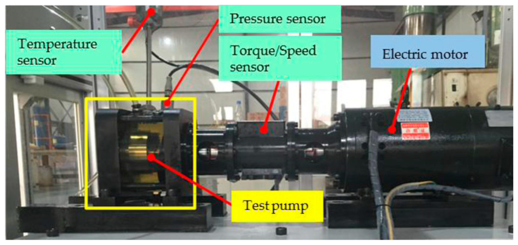
The experiments were carried out on the test rig shown in Figure 3. The shaft is driven by an electric motor via a flexible coupling transmitting the rotation speed up to 16,000 rpm. A torque-speed sensor is installed between the electric motor and the test pump, which can obtain shaft speed and pump torque. A temperature sensor and a pressure sensor are installed at the top of the test pump, which can obtain the temperature and pressure in the test pump. A test pump can be used to simulate the churning losses due to rotating parts in axial piston pumps. The casing of the test pump is an annular cylinder with 32.5 mm thickness made of Plexiglas in order to observe the flow state. Table 1 gives the details of sensors related to this study.
The churning losses can be represented as the shaft torque losses determined by torque measurements using a torque speed sensor. The shaft is supported by one pair of identical shielded and sealed ball bearings whose contributions to the friction torque have been experimentally determined and subtracted from total torque measurements to obtain the net contributions of churning torque losses. To maintain a constant pressure in the casing of the test pump, the pump is tested under the no-load operating condition which means that the outlet is directly connected to the pipeline without a pressure valve, and the casing pressure depends on the drain line. To maintain a constant temperature in the casing of the test pump, the auxiliary pump is arranged for the circulation of the oil; the oil cooler and overflow heating system are arranged to control the oil temperature in the oil tank. Thus, churning losses power is deduced by subtracting the wet casing torque acting on the shaft from the dry casing torque acting on the shaft on the same test stand. The experimental churning losses power can be written as:
where Mc is the experimental churning losses torque, Mw is the experimental torque acting on the shaft with oil in the casing, and Md is the experimental torque acting on the shaft without oil.
In fact, the above method for the churning losses measurement of axial piston pumps was somewhat similar to the one for measuring churning losses in bent-axis piston motors proposed by Rahmfeld et al. in References [29,30]. Rahmfeld et al. also measured the churning losses in a bent-axis piston motor with full and dry casing operation by testing the different torque losses, as shown in Equation (7). However, the test rig built by Rahmfeld et al. adopted a motor operated in pumping mode to measure the churning losses in the bent-axis motor. As a result, this test measured the influence of the operation conditions on total churning losses of piston pumps. However, in this way, the mechanical friction losses in three friction pairs under different lubrication conditions would affect the test accuracy. The churning losses due to the rotating cylinder block and pistons have not been measured respectively. In this paper, the cylinder block and pistons rotated while all other friction pairs were removed (see Figure 4).
The test pump was designed based on a high-speed axial piston pump prototype used for aircraft in References [31,32]. Table 2 provides the geometric dimensions and information regarding the test pump, which is the same as the high-speed axial piston pump prototype. Considering that the high-speed axial piston pump prototype operates at a high speed and low pressure at take-off and landing of the aircraft, the test pump operating conditions which have been included in the investigation can be summarized in Table 3.
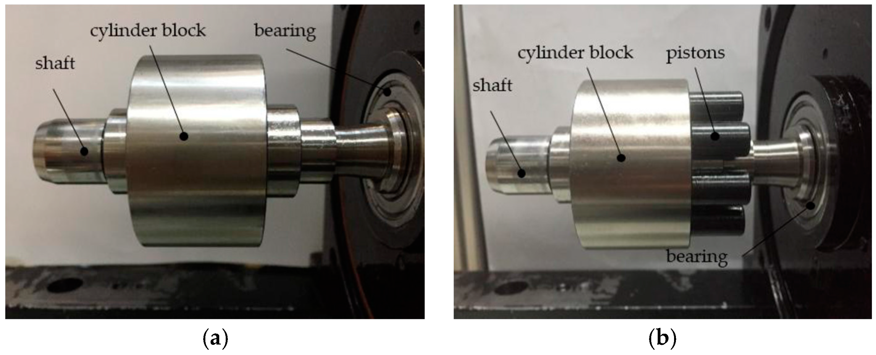
As shown in Figure 4, the test pump has only a piston/cylinder pair and ignores the small influence on the churning losses of non-rotating parts, such as the swash plate and valve plate. The churning losses due to the rotating cylinder block can be obtained by measuring the subtraction of churning losses torque acting on the shaft by the cylinder block rotating alone in the casing filled with oil and dry casing (see Figure 5a). The test of churning losses power due to the rotation of the cylinder block Pcc can be expressed as:
where Mcc is the experimental churning losses torque due to the rotation of the cylinder block, Mwcc is the experimental torque acting on the shaft due to the rotation of the cylinder block with oil in the casing, and Mdcc is the experimental torque acting on the shaft due to the rotation of the cylinder block without oil in the casing.
Figure 5 shows the churning losses due to the pistons by measuring the subtraction of churning losses of the piston/cylinder and cylinder block. The test of churning losses power due to pistons Pcp can be expressed as:
where Mcp is the experimental churning losses torque due to the pistons, Mccp is the experimental churning losses torque due to the pistons and the rotating cylinder block, Mwccp is the experimental torque acting on the shaft due to the pistons and the rotating cylinder block with oil in the casing, and Mdccp is the experimental torque acting on the shaft due to the pistons and the rotating cylinder block without oil in the casing.
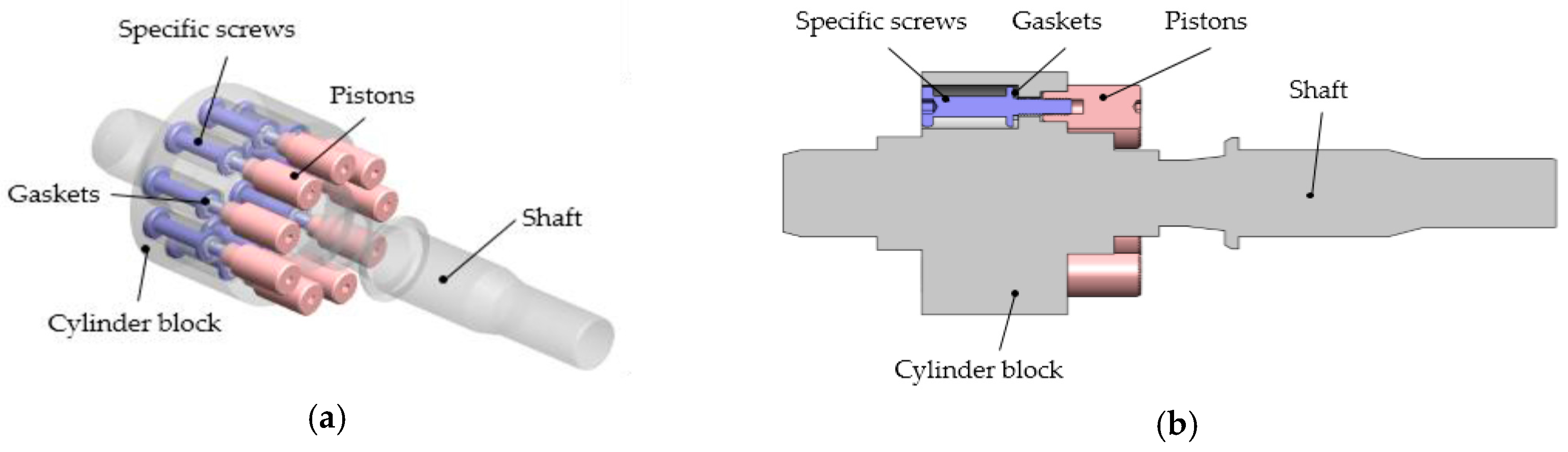
However, at the same time, this new attempt also brings some challenges on testing the churning losses. The first challenge is that the fixation of the pistons becomes a problem due to removing the structure of the swash plate. As shown in Figure 6, test pistons are fixed by the specific screws and gaskets mounted within the cylinder block bores at equal angular intervals around the centerline of the cylinder block. The cylinder block and shaft are integrated together in the test pump to remove the spline friction torque losses on the impact of the churning losses.
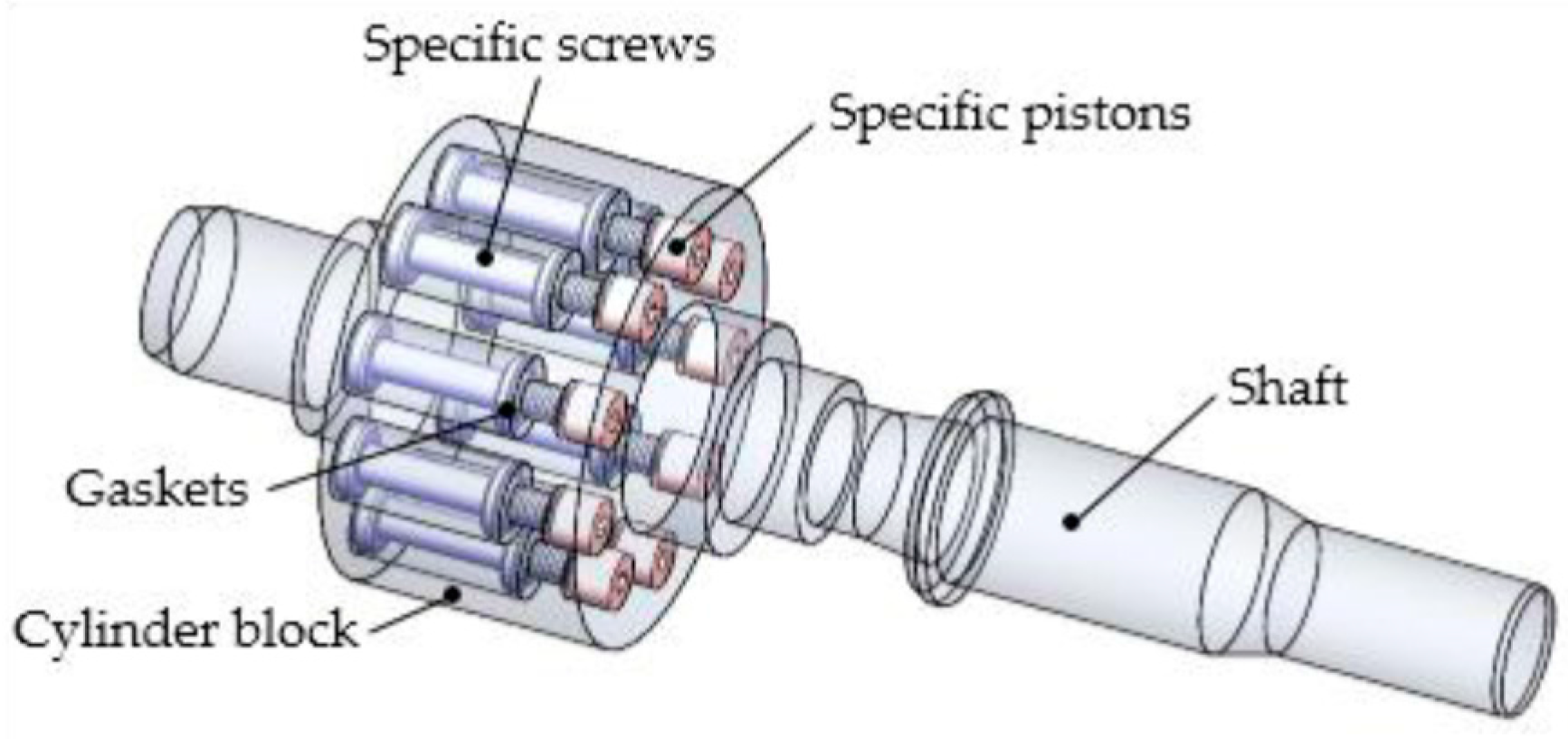
The second challenge is associated with accurately estimating the influence of the cylinder block and pistons on churning losses. The integration of the cylinder block and shaft churning losses test results can be considered as the effect of the rotating cylinder block on churning losses. As can be seen in Figure 7, the piston bores are filled with specific screws to prevent these effects on the test of churning losses due to the rotating cylinder block.
The fixed pistons only rotate in the test pump without reciprocating motion, and the dimensions of the pistons are the same as the pistons immersed in the real pump oil-churning parts. It can effectively test the influence of the pistons on churning losses under small displacement (i.e., small swash-plate angle) working conditions.
4. Results
4.1. Effects of the Rotating Cylinder Block
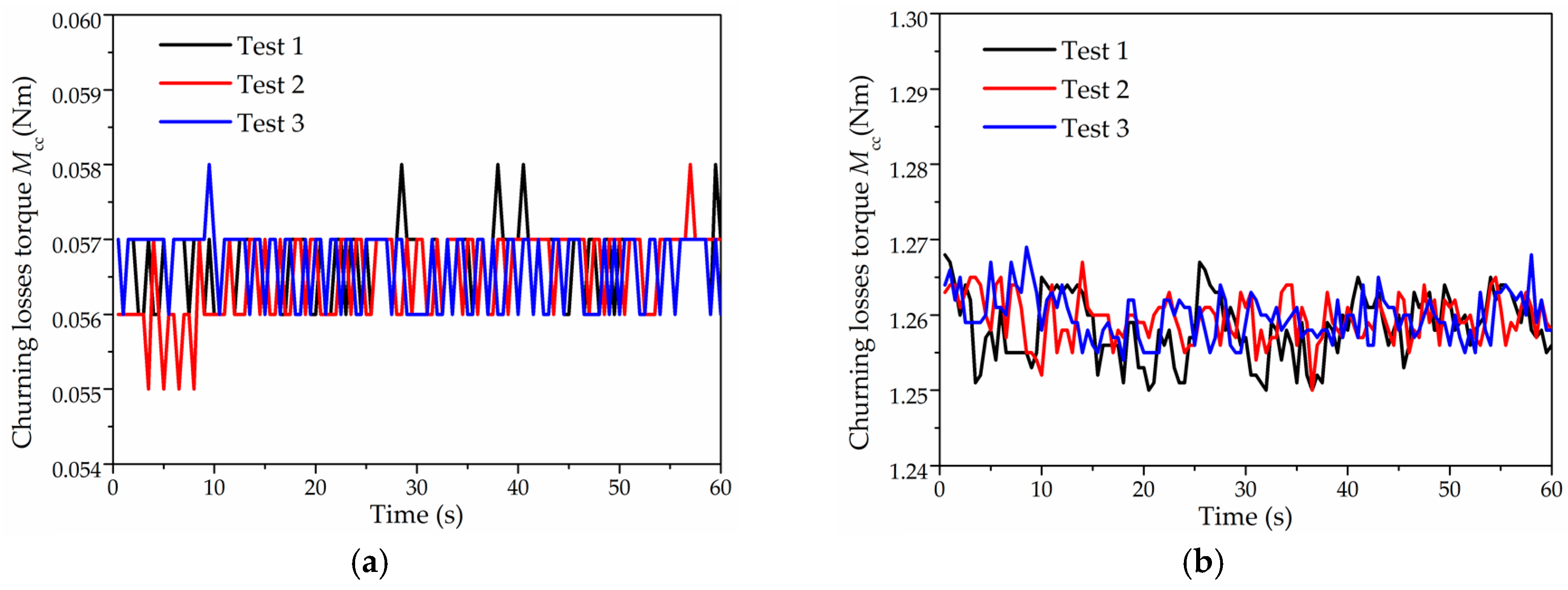
Figure 8 shows the original test results of the rotating cylinder block at 1500 rpm and 12,000 rpm. Tests were performed three times under the same conditions, where oil temperature was maintained at (35 ± 1) °C and oil pressure was maintained at (1.02 ± 0.01) bar. The deviation of churning losses torque after three times is small, which indicates that the tests have excellent repeatability at low and high speed.
As shown in Figure 9, the results of the rotating cylinder block at various speeds are presented in the form of mean values acquired under the same conditions. In contrast to the existing model, Figure 9a shows that the deviation of the measured churning losses due to the rotating cylinder block is small in comparison with the calculated results before 3000 rpm. However, the measured churning losses due to the rotating cylinder block increase significantly after 3000 rpm. This can be explained by the fact that fluid flow states change from laminar flows to turbulent flows with the Reynolds number increased in Reference [27], as the Reynolds number is a function of the rotation speed as shown in Re = ωRctρμ−1 in Reference [20]. The flow states may change from laminar flows to turbulent flows because the Reynolds number increases from 103 to 104 with the speed increasing from 3000 to 12,000 rpm. Also, churning losses due to the rotating cylinder block change from friction losses to turbulent losses, with the Reynolds increasing greatly. Laminar flow assumption in the mathematical model is not appropriate; turbulent shear stress is far greater than the laminar viscous friction [33,34]. Thus, the calculated results are tiny for the churning losses due to laminar viscous friction, in contrast with the measured results due to the turbulent shear stress losses at high rotation speeds. It is also shown in Figure 10 that there is a difference in fluid condition outside the cylinder block at two different speeds of the test pump. The flowing area outside the cylinder block is small and regular at low rotation speeds. However, the flowing area outside the cylinder block is significantly increased and tends to be disordered at high rotation speeds.
Furthermore, when comparing Figure 9a,b, it is noticeable that churning losses torque increases by about 22 times and the churning losses power increases by about 177 times produced by the rotating cylinder block, with increased speed from 1500 rpm to 12,000 rpm. The results indicate that the churning torque losses due to the rotating cylinder block change relatively little, while the churning power losses will increase seriously with speed increased by 8 times. Therefore, the rotating cylinder block has a significant influence on churning losses, particularly at the high rotation speed. The effects of the pistons on churning losses will be discussed in the following sections.
4.2. Effects of the Pistons
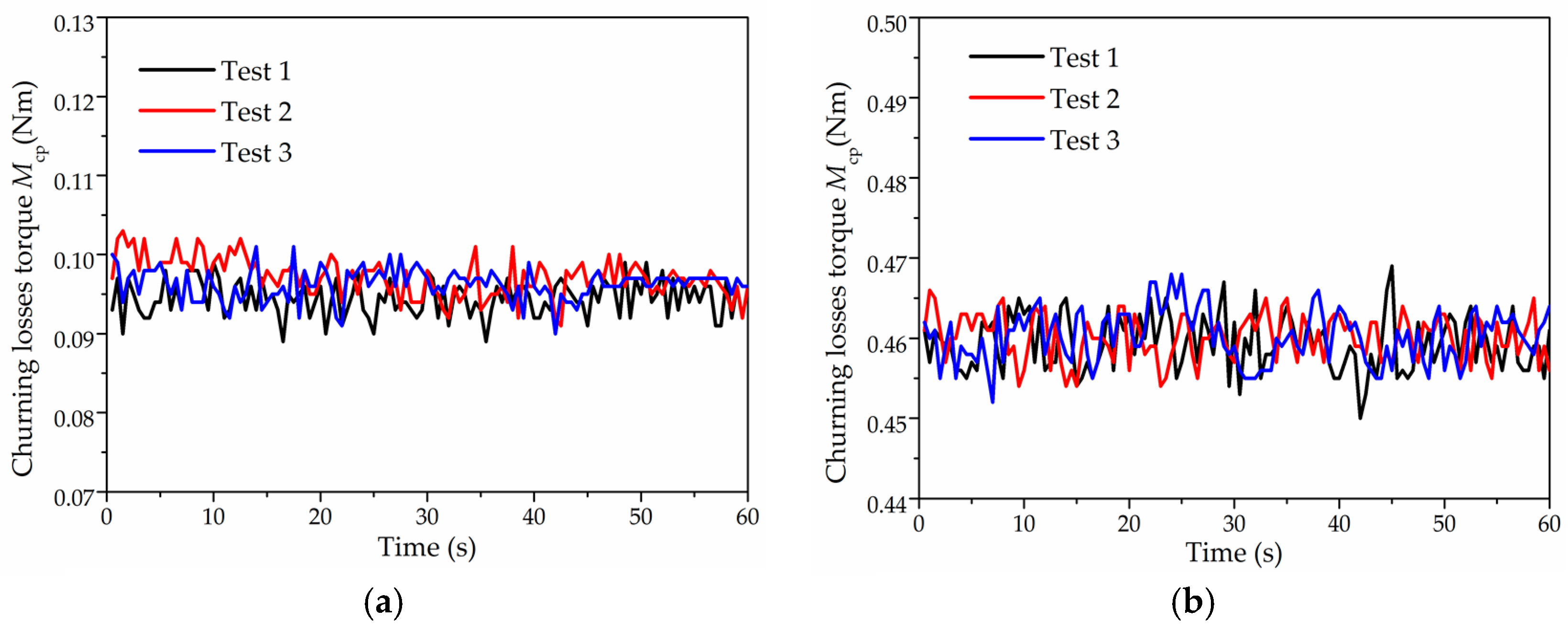
Figure 11 shows the test results of pistons at 1500 rpm. Tests were performed three times under the same conditions, where oil temperature maintained at (35 ± 1) °C and oil pressure were maintained at (1.01 ± 0.01) bar. As shown in Figure 11, the deviation of the churning losses torque is higher than the results of the rotating cylinder block, because the motion of the pistons leads to vibration. However, the size of the deviation value is still small, which indicates that the repeatability of the tests is good at low and high speed.
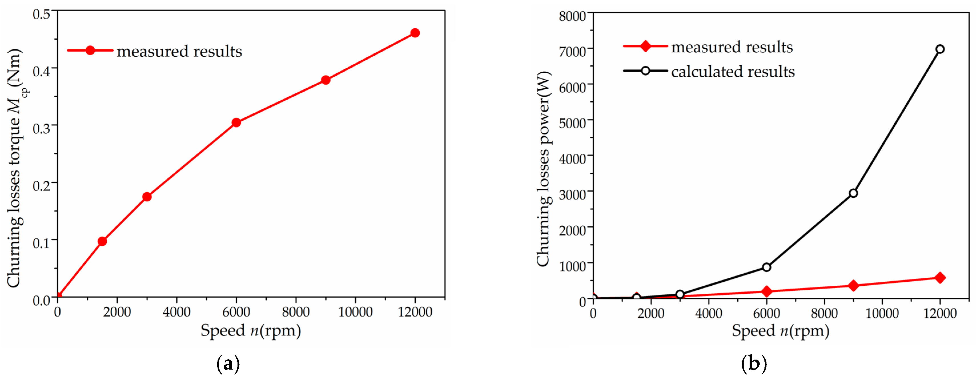
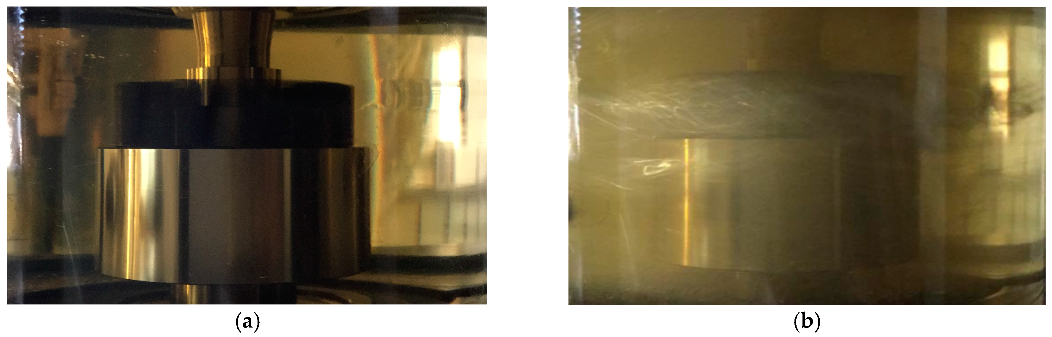
In Figure 12, the results of pistons at various speeds are presented in the form of mean values acquired under the same conditions. An average drag coefficient of the calculated pistons is 0.96 in Figure 12b, because the drag coefficient Cd is related to the Reynolds number, according to [27]. It can be seen from Figure 12b that the churning losses due to the pistons increase with rotation speed in a similar trend as the calculated results before 3000 rpm. However, the churning losses due to the pistons increase relatively slowly after 3000 rpm, in comparison with those in the rotating cylinder block, because multi-pistons cover the circling flow which leads to the decrease of fluid flow velocity and reduction of flow resistance among the pistons. The literature [35,36,37,38] indicates that there is a reduction factor in the flow resistance around the multi-pistons, and the reduction factor may increase because of the effect of the pistons covering each other as rotation speed increases. The higher the rotation speed, the greater the flow rate in the area without pistons, and the smaller the flow velocity between the pistons. Thus, the measured results are low for the churning losses due to the reduction factor, in contrast with the calculated results at high rotation speed. Moreover, Figure 13 shows the difference in a fluid condition outside the pistons at two test pump speeds; it can be obtained that the cavitation phenomenon occurs in fluid flow outside the pistons. The fluid tends to flow to the area without pistons due to the effects of pistons covering at high rotation speeds. The flow resistance among the pistons decreases due to the cavitation, especially at high rotation speeds. Finally, circling flow resistance relatively decreases with increasing speed, in comparison to the mathematical model which ignores the cavitation and the reduction factor in flow resistance around the multi-pistons.
Furthermore, when comparing Figure 12a,b, it is noticeable that churning losses torque increased by about five times and the churning losses power increased by about 38 times, produced by the pistons as rotation speed increased from 1500 rpm to 12,000 rpm. From the results, one may conclude that the increased rate of the churning losses torque produced by the pistons decreased as rotation speed increased, in comparison with those produced by the rotating cylinder block. However, there is still relatively big churning losses power due to the pistons, as shown in Figure 12b. It is also observed that small torque losses may bring high churning energy losses with the increase of rotation speed.
5. Discussion
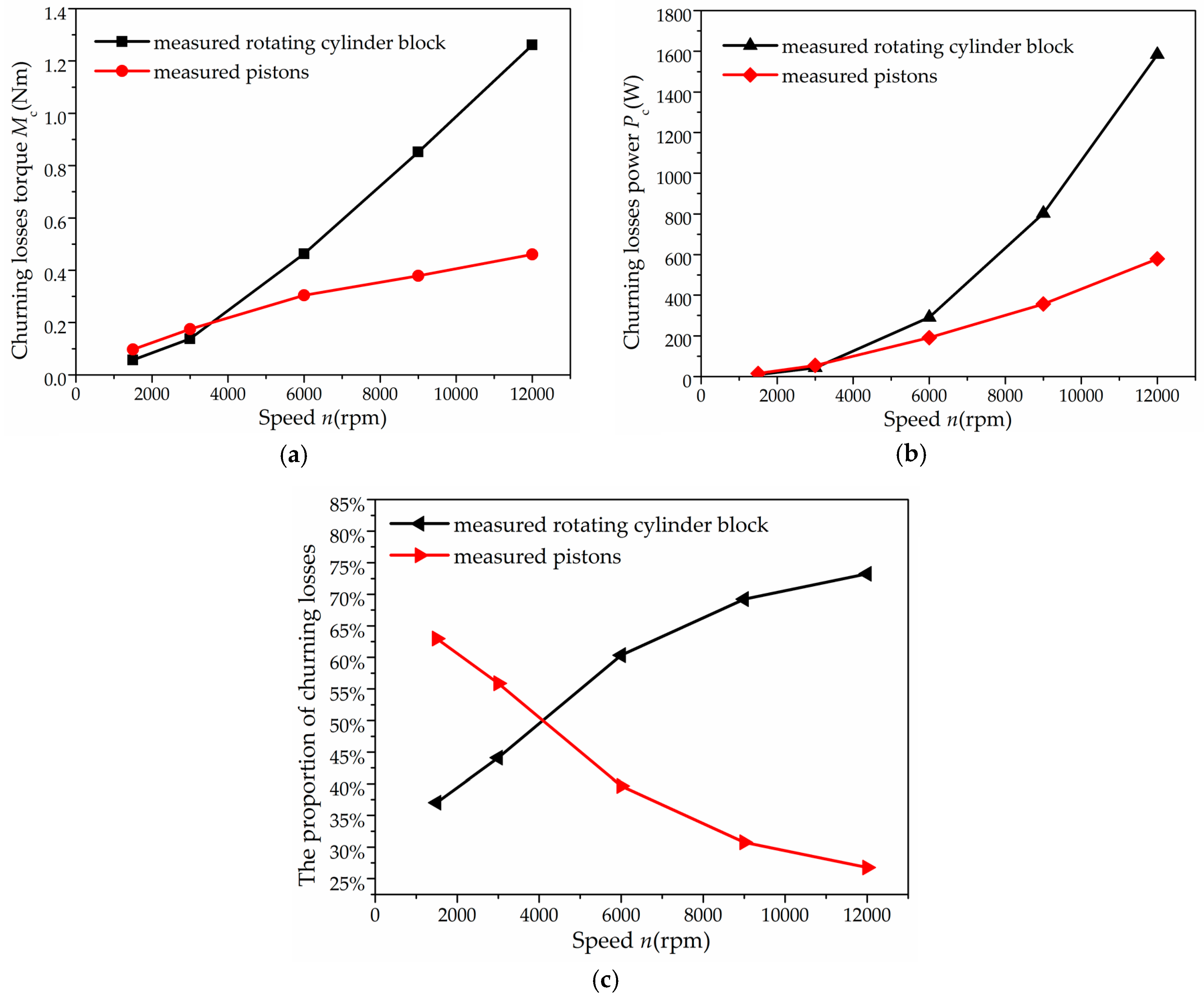
As a result of the previous analysis, two investigated factors of the rotating cylinder block and pistons contribute to churning losses, and these energy losses cannot be ignored, especially at high speed. The concept of churning losses reported in the literature was developed based on Newton inner friction, and thus entirely ignored the turbulence effects. Representative theories are Jang [18], Zecchi et al. [20], and Rahmfeld et al. [29] for churning losses due to the rotating cylinder block and pistons. The churning losses studied in these theories show that the pistons in an axial piston machine have a higher influence on the churning losses than the rotating cylinder block. However, the churning losses produced by the rotating cylinder block are significantly higher than the pistons after 3000 rpm (see Figure 14a,b). An explanation is that the resistance of one piston may be smaller due to the piston assembly, and the flow state of the rotating cylinder block may change from laminar to turbulent at high rotation speeds. The proportion of churning losses due to the rotating cylinder block increases obviously with rotation speed, and the proportion of churning losses due to the pistons decreases.
In Figure 14c, the intersection of two curves shows that the proportion of churning losses produced by the rotating cylinder block equals the churning losses produced by the pistons, and the corresponding abscissa is the speed named as the critical speed. The rotation speed of the axial piston pumps is usually lower than the critical speed for industrial application; then the energy losses caused by the rotating cylinder block are much weaker than that between the pistons. However, the energy losses caused by the rotating cylinder block are much higher than that between the pistons beyond the critical speed for the axial piston pumps used in aeronautics and astronautics. Therefore, we plan to experimentally explore the methods for reducing the churning losses produced by the rotating cylinder block of the axial piston pumps used in aeronautics and astronautics in future work.
6. Conclusions
In this study, a newly designed test rig is introduced to investigate the churning losses in an axial piston pump experimentally. The focus of this work mainly lies in the description of the effects of the rotating cylinder block and pistons on churning losses by experiments, and the presentation of the first measured results. Presented measurements exhibit the capacity of the test rig to detect the churning losses, and to further evaluate the proportion of the rotating cylinder block and pistons on churning losses. According to the experimental results, the following conclusions can be drawn:
Firstly, the churning losses increase with the rotation speed. Secondly, the mathematical model for the churning losses based on the assumption of laminar flow cannot suit under the high rotation speed condition. Finally, the pistons have less influence than the rotating cylinder block on churning losses beyond the critical speed in axial piston pumps. In other words, the rotating cylinder block is a dominant influence on churning losses at high rotation speeds.
This experimental finding may provide a new insight into churning losses. Taking advantage of the full capability of the test rig, future research on churning losses will focus on methods to reduce churning losses based on considering turbulent flow, especially churning losses produced by the rotating cylinder block at high rotation speeds.
Acknowledgments
This work was supported by the National Basic Research Program of China (973 Program) (No. 2014CB046403) and the National Natural Science Foundation of China (No. U1509204).
Author Contributions
Bing Xu and Junhui Zhang conceived and designed the experiments; Ying Li and Fei Lv performed the experiments and analyzed the data; Junhui Zhang and Ying Li contributed to the discussion of this study; Ying Li and Min Pan wrote the paper.
Conflicts of Interest
The authors declare no conflict of interest.
Nomenclature
| μ | The dynamic viscosity of the hydraulic fluid (Pa·s) |
| R | The radius of the cylinder block (m) |
| Rc | The radius of the cylinder block (m) |
| R | The pitch circle radius of piston bores (m) |
| lc | The length of the cylinder block (m) |
| ω | The rotation angular velocity (rad/s) |
| n | The rotation speed (rpm) |
| t | The gap between the cylinder block and the housing internal surface (m) |
| Cd | The drag coefficient |
| ρ | The density of the hydraulic fluid (kg/m3) |
| d | The diameter of the piston (m) |
| li | The length of the ith piston out of the cylinder block at the one point (m) |
| l0 | The length of the piston out of the cylinder block at the outer dead point (m) |
| z | The number of pistons |
| γ | The swash plate angle (°) |
| Fv | The viscous friction (N) |
| Fi | The pressure drag (N) |
| Mc | The experimental churning losses torque (Nm) |
| Mw | The experimental torque acting on the shaft with oil in the casing (Nm) |
| Md | The experimental torque acting on the shaft without oil in the casing (Nm) |
| Mcc | The experimental churning losses torque due to the rotation of the cylinder block (Nm) |
| Mcm | The mathematical churning losses torque due to the rotation of the cylinder block (Nm) |
| Mwcc | The experimental torque acting on the shaft due to the rotation of the cylinder block with oil in the casing (Nm) |
| Mdcc | The experimental torque acting on the shaft due to the rotation of the cylinder block without oil in the casing (Nm) |
| Mcp | The experimental churning losses torque due to pistons (Nm) |
| Mccp | The experimental churning losses torque due to pistons and the rotating cylinder block (Nm) |
| Mwccp | The experimental torque acting on the shaft due to pistons and the rotating cylinder block with oil in the casing (Nm) |
| Mdccp | The experimental torque acting on the shaft due to pistons and the rotating cylinder block without oil in the casing (Nm) |
| Pcm | The mathematical viscous friction power (W) |
| Ppm | The mathematical pressure drag power (W) |
| Pc | The experimental churning losses power (W) |
| Pcc | The experimental churning losses power due to the rotation of the cylinder block (W) |
| Pcp | The experimental churning losses power due to pistons (W) |
| Re | Reynolds number |
References
- Yang, H.; Zhang, B.; Xu, B. Development of axial piston pump/motor technology. Chin. J. Mech. Eng. 2008, 44, 1–8. [Google Scholar] [CrossRef]
- Yang, H.; Pan, M. Engineering research in fluid power: A review. J. Zhejiang Univ. SCIENCE A 2015, 16, 427–442. [Google Scholar] [CrossRef]
- Casoli, P.; Riccò, L.; Campanini, F.; Andrea, B. Hydraulic Hybrid Excavator—Mathematical Model Validation and Energy Analysis. Energies 2016, 9, 1002. [Google Scholar] [CrossRef]
- McCandlish, D.; Dorey, R.E. The mathematical modelling of hydrostatic pumps and motors. Proc. Inst. Mech. Eng. Part B J. Eng. Manuf. 1984, 198, 165–174. [Google Scholar] [CrossRef]
- Manring, N.D. Torque on the Cylinder Block of an Axial-Piston Swash-Plate Type Hydrostatic Pump. Ph.D. Thesis, Iowa State University, Ames, IA, USA, 1996. [Google Scholar]
- Bronshteyn, L.A.; Kreiner, J.H. Energy efficiency of industrial oils. Tribol. Trans. 1999, 42, 771–776. [Google Scholar] [CrossRef]
- Murrenhoff, H.; Piepepenstock, U.; Kohmäscher, T. Analysing losses in hydrostatic drives. In Proceedings of the JFPS International Symposium on Fluid Power, Toyama, Japan, 15–18 September 2008. [Google Scholar]
- Jeong, H.S.; Kim, H.E. A novel performance model given by the physical dimensions of hydraulic axial piston motors: Experimental analysis. J. Mech. Sci. Technol. 2007, 21, 630–641. [Google Scholar] [CrossRef]
- Gao, M.; Huang, H.; Li, X.; Liu, Z. A Novel Method to Quickly Acquire the Energy Efficiency for Piston Pumps. J. Dyn. Syst. Meas. Control 2016, 138, 1–9. [Google Scholar] [CrossRef]
- Wilson, W.E. Rotary-pump theory. Trans. ASME 1946, 68, 371–384. [Google Scholar]
- Ivantysynova, M.; Lasaar, R. An investigation into micro-and macrogeometric design of piston/cylinder assembly of swash plate machines. Int. J. Fluid Power 2004, 5, 23–36. [Google Scholar] [CrossRef]
- Shi, X.; Manring, N.D. A torque efficiency model for an axial-piston, swash-plate type, hydrostatic pump. In Proceedings of the Bath Workshop on Power Transmission and Motion Control, Bath, UK, 12–14 September 2001. [Google Scholar]
- Manring, N.D.; Zhang, Y. The improved volumetric-efficiency of an axial-piston pump utilizing a trapped-volume design. Trans. Am. Soc. Mech. Eng. J. Dyn. Syst. Meas. Control 2001, 123, 479–487. [Google Scholar] [CrossRef]
- Bergada, J.M.; Kumar, S.; Davies, D.L.; Watton, J. A complete analysis of axial piston pump leakage and output flow ripples. Appl. Math. Model. 2012, 36, 1731–1751. [Google Scholar] [CrossRef]
- Xu, B.; Hu, M.; Zhang, J.; Su, Q. Characteristics of volumetric losses and efficiency of axial piston pump with respect to displacement conditions. J. Zhejiang Univ. SCIENCE A 2016, 17, 186–201. [Google Scholar] [CrossRef]
- Axial Piston Pump of the Type Having Intersecting Axes. Available online: http://www.freepatentsonline.com/y2002/0000159.html (accessed on 9 May 2017).
- Hydraulic Innovations-Systems, Subsystems, and Components, p. 8. Available online: http://www.parker.com/Literature/Hydraulic%20Systems%20Division/Parker_HSD.6-09.pdf (accessed on 9 May 2017).
- Jang, D.S. Verlustanalyse an Axialkolbeneinheiten. Ph.D. Thesis, RWTH Aachen University, Aachen, Germany, 1997. [Google Scholar]
- Håkan, O. Power losses in an axial piston pump used in industrial hydrostatic transmissions. In Proceedings of the Eighth Scandinavian International Conference on Fluid Power, Tampere, Finland, 7–9 May 2003. [Google Scholar]
- Zecchi, M.; Mehdizadeh, A.; Ivantysynova, M. A novel approach to predict the steady state temperature in ports and case of swash plate type axial piston machines. In Proceedings of the 13th Scandinavian International Conference on Fluid Power, Linköping, Sweden, 3–5 June 2013. [Google Scholar]
- Shang, L.; Ivantysynova, M. Port and case flow temperature prediction for axial piston machines. Int. J. Fluid Power 2015, 16, 35–51. [Google Scholar]
- Thiagarajan, D.; Vacca, A. Investigation of Hydro-Mechanical Losses in External Gear Machines: Simulation and Experimental Validation. In Proceedings of the BATH/ASME 2016 Symposium on Fluid Power and Motion Control, Bath, UK, 7–9 September 2016. [Google Scholar]
- Thiagarajan, D.; Vacca, A. Mixed Lubrication Effects in the Lateral Lubricating Interfaces of External Gear Machines: Modelling and Experimental Validation. Energies 2017, 10, 111. [Google Scholar] [CrossRef]
- Changenet, C.; Leprince, G.; Ville, F.; Velex, P. A note on flow regimes and churning loss modeling. J. Mech. Des. 2011, 133, 121009. [Google Scholar] [CrossRef]
- Xu, B.; Li, Y.; Zhang, J.; Chao, Q. Modeling and analysis of the churning losses characteristics of swash plate axial piston pump. In Proceedings of the International Conference on Fluid Power and Mechatronics, Harbin, China, 5–7 August 2015. [Google Scholar]
- Enekes, C.P. Ausgewählte Maßnahmen zur Effizienzsteigerung von Axialkolbenmaschinen. Ph.D. Thesis, RWTH Aachen University, Aachen, Germany, 2012. [Google Scholar]
- Schlichting, H.; Gersten, K.; Krause, E.; Oertel, H. Boundary-Layer Theory; McGraw-Hill: New York, NY, USA, 1960. [Google Scholar]
- Theissen, H.; Gels, S.; Murrenhoff, H. Reducing Energy Losses in Hydraulic Pumps. In Proceedings of the International Conference on Fluid Power Transmission and Control, Hangzhou, China, 9–11 April 2013. [Google Scholar]
- Rahmfeld, R.; Marsch, S.; Göllner, W.; Lang, T.; Dopichay, T.; Untch, J. Efficiency potential of dry case operation for bent-axis motors. In Proceedings of the 8th International Fluid Power Conference, Dresden, Germany, 26–28 March 2012. [Google Scholar]
- Rahmfeld, R.; Marsch, S.; Göllner, W.; Lang, T.; Dopichay, T.; Untch, J. Mehr Effizienz bei hydrostatischen Einheiten. Ölhydraulik und Pneumatik 2012, 56, 7–8. [Google Scholar]
- Xu, B.; Chao, Q.; Zhang, J.; Chen, Y. Effects of the dimensional and geometrical errors on the cylinder block tilt of a high-speed EHA pump. Meccanica 2016. [Google Scholar] [CrossRef]
- Zhang, J.; Chao, Q.; Xu, B. Analysis of the cylinder block tilting inertia moment and its effect on the performance of high-speed electro-hydrostatic actuator pumps of aircraft. Chin. J. Aeronaut. 2017. [Google Scholar] [CrossRef]
- Kármán, T. Über laminare und turbulente Reibung. ZAMM J. Appl. Math. Mech./Z. Angew. Math. Mech. 1921, 1, 233–252. [Google Scholar] [CrossRef]
- Wolfshtein, M. Some comments on turbulence modelling. Int. J. Heat Mass Transf. 2009, 52, 4103–4107. [Google Scholar] [CrossRef]
- Zdravkovich, M.M. REVIEW—Review of flow interference between two circular cylinders in various arrangements. J. Fluids Eng. 1977, 99, 618–633. [Google Scholar] [CrossRef]
- Zdravkovich, M.M. Flow induced oscillations of two interfering circular cylinders. J. Sound Vib. 1985, 101, 511–521. [Google Scholar] [CrossRef]
- Igarashi, T. Characteristics of the flow around two circular cylinders arranged in tandem: 1st report. Bull. JSME 1981, 24, 323–331. [Google Scholar] [CrossRef]
- Kim, S.; Alam, M.M. Characteristics and suppression of flow-induced vibrations of two side-by-side circular cylinders. J. Fluids Struct. 2015, 54, 629–642. [Google Scholar] [CrossRef]
Figure 1.
Configuration of a conventional axial piston pump.
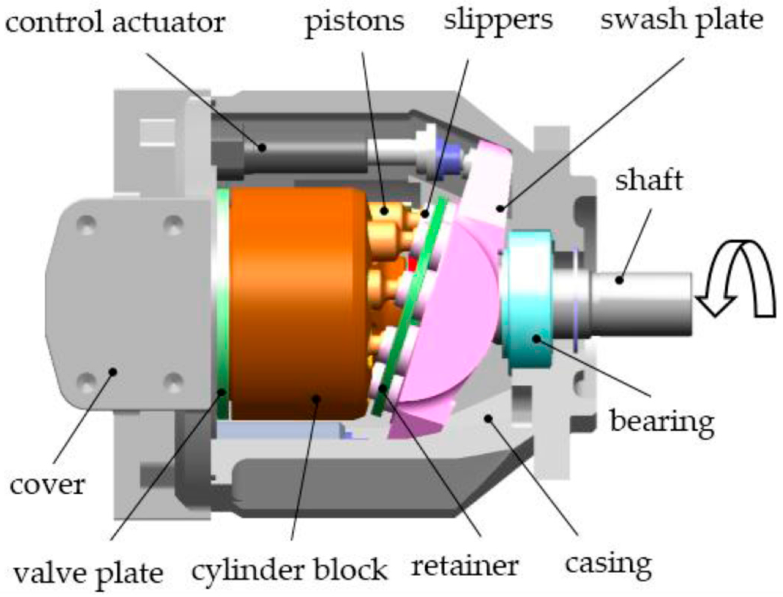
Figure 2.
Schematic representation of churning losses in axial piston pumps.
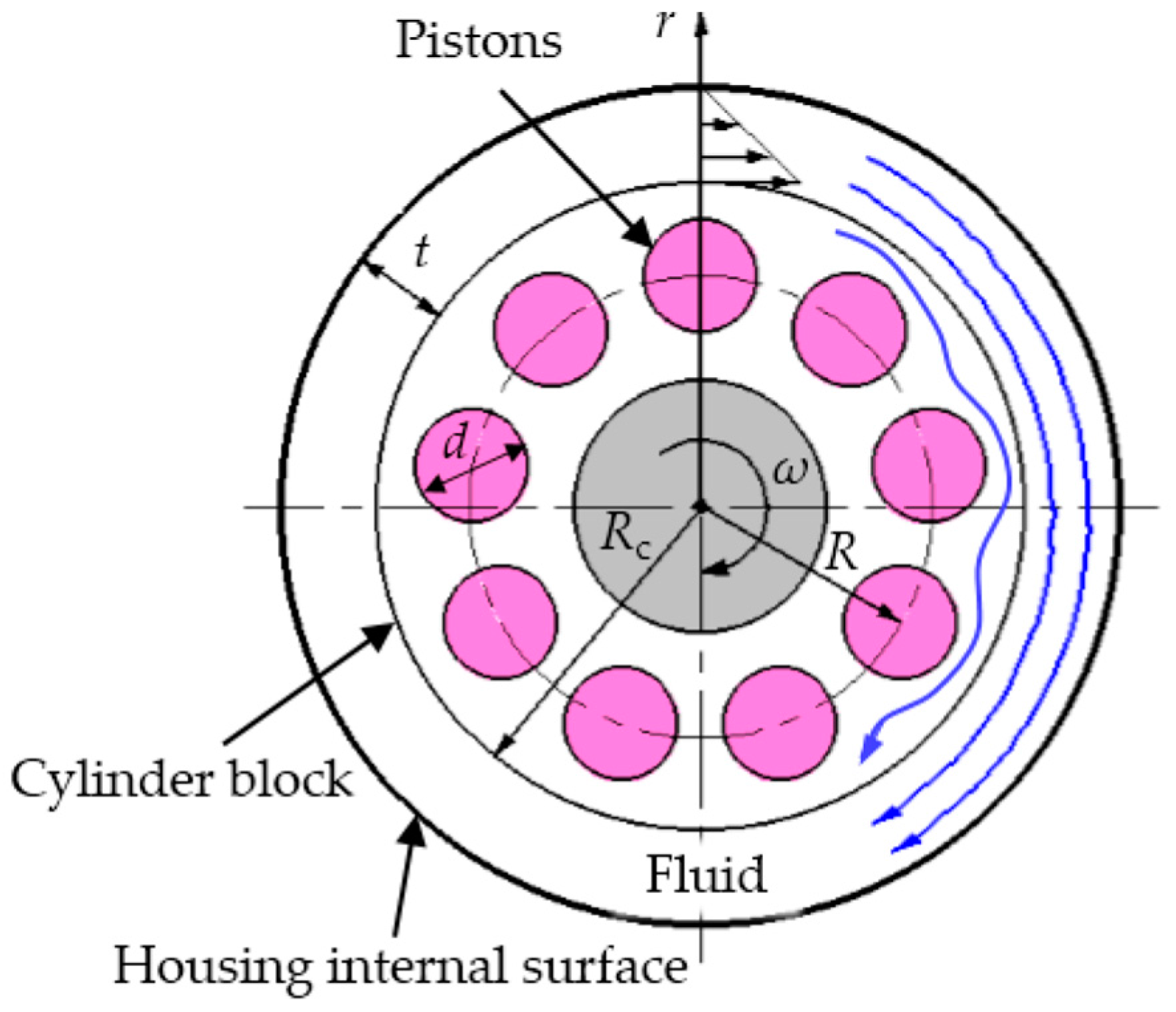
Figure 3.
The test rig that was used to conduct the experiments of this research.

Figure 4.
3D view of the test pump: (a) global 3D view of the test pump; (b) a frontal cross-section of the test pump.
Figure 4.
3D view of the test pump: (a) global 3D view of the test pump; (b) a frontal cross-section of the test pump.
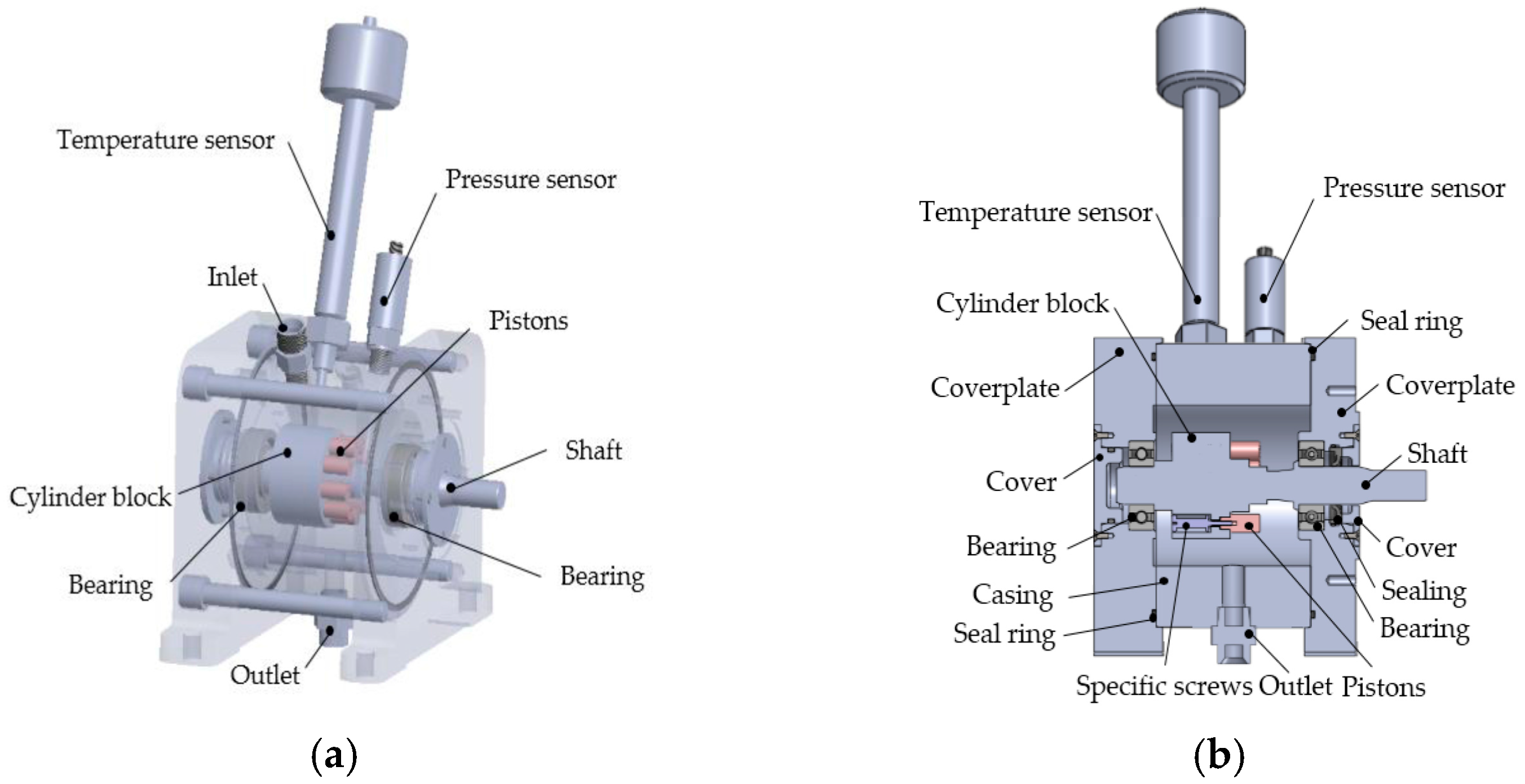
Figure 5.
Churning losses testing: (a) test of churning losses due to the rotating cylinder block; and (b) test of churning losses due to the pistons.
Figure 5.
Churning losses testing: (a) test of churning losses due to the rotating cylinder block; and (b) test of churning losses due to the pistons.

Figure 6.
3D model of test pistons and cylinder block: (a) An axonometric drawing of test pistons and cylinder block; (b) A cross-section of the test pistons and cylinder block.
Figure 6.
3D model of test pistons and cylinder block: (a) An axonometric drawing of test pistons and cylinder block; (b) A cross-section of the test pistons and cylinder block.

Figure 7.
3D view of the test piston bores.

Figure 8.
Test churning losses torque of the rotating cylinder block: (a) test churning losses torque of the rotating cylinder block at 1500 rpm; and (b) test churning losses torque of the rotating cylinder block at 12,000 rpm.
Figure 8.
Test churning losses torque of the rotating cylinder block: (a) test churning losses torque of the rotating cylinder block at 1500 rpm; and (b) test churning losses torque of the rotating cylinder block at 12,000 rpm.

Figure 9.
Experimental results of the rotating cylinder block at various speeds: (a) test churning losses torque of the rotating cylinder block at different speeds; and (b) test churning losses power of the rotating cylinder block at different speeds.
Figure 9.
Experimental results of the rotating cylinder block at various speeds: (a) test churning losses torque of the rotating cylinder block at different speeds; and (b) test churning losses power of the rotating cylinder block at different speeds.
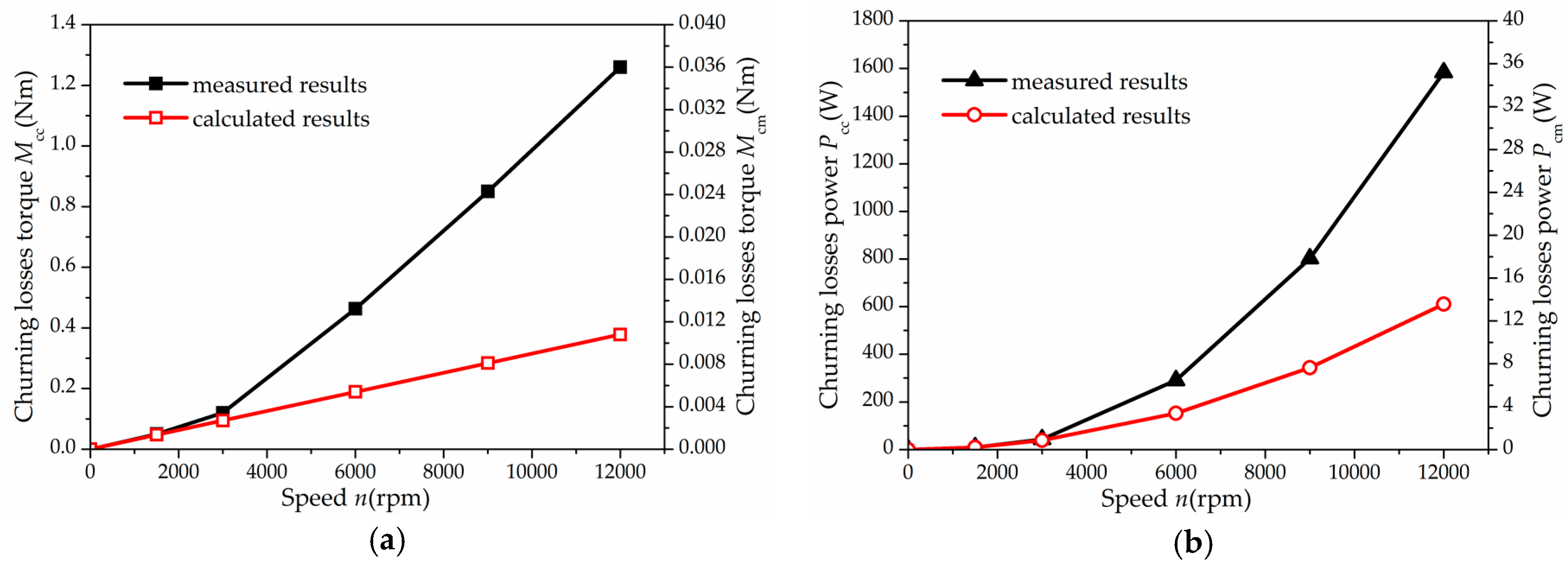
Figure 10.
Fluid condition outside the cylinder block at two test pump speeds: (a) fluid condition outside the cylinder block at 1500 rpm; (b) fluid condition outside the cylinder block at 12,000 rpm.
Figure 10.
Fluid condition outside the cylinder block at two test pump speeds: (a) fluid condition outside the cylinder block at 1500 rpm; (b) fluid condition outside the cylinder block at 12,000 rpm.
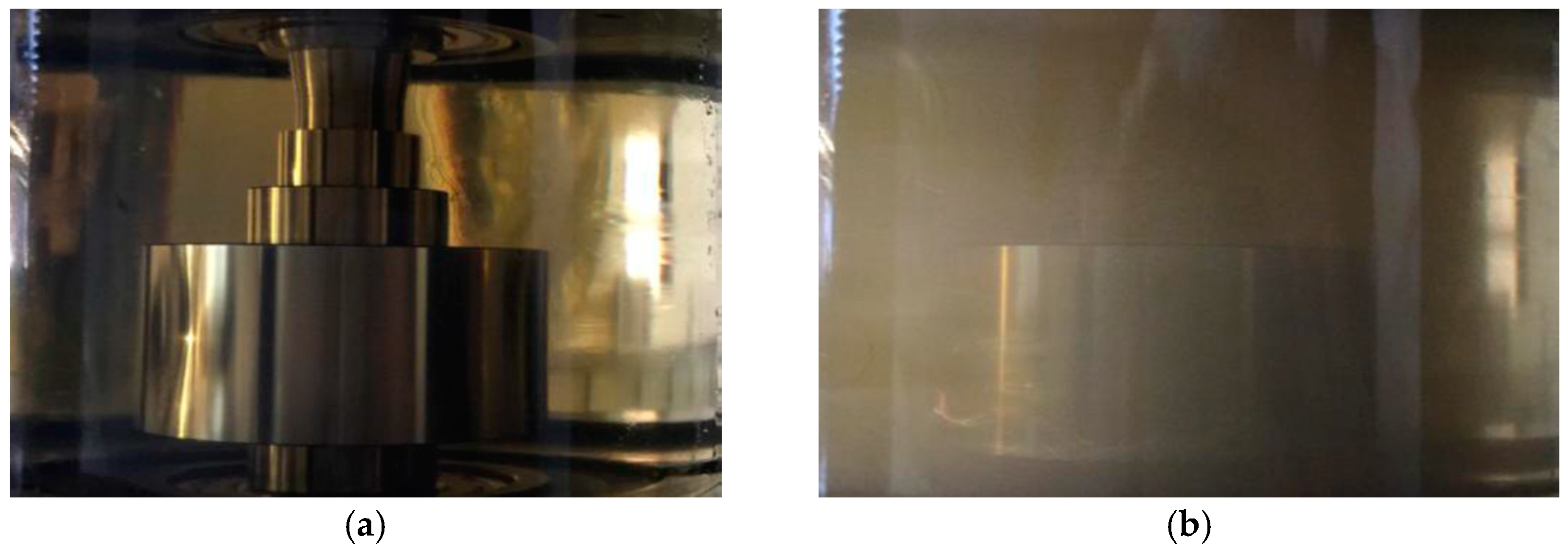
Figure 11.
Test churning losses torque of pistons: (a) test churning losses torque of pistons at 1500 rpm; and (b) test churning losses torque of pistons at 12,000 rpm.
Figure 11.
Test churning losses torque of pistons: (a) test churning losses torque of pistons at 1500 rpm; and (b) test churning losses torque of pistons at 12,000 rpm.

Figure 12.
Experimental results of pistons at various speeds: (a) test churning losses torque of pistons at different speeds; and (b) test churning losses power of pistons at different speeds.
Figure 12.
Experimental results of pistons at various speeds: (a) test churning losses torque of pistons at different speeds; and (b) test churning losses power of pistons at different speeds.

Figure 13.
Fluid condition outside the pistons at two test pump speeds: (a) fluid condition outside the pistons at 1500 rpm; and (b) fluid condition outside the pistons at 12,000 rpm.
Figure 13.
Fluid condition outside the pistons at two test pump speeds: (a) fluid condition outside the pistons at 1500 rpm; and (b) fluid condition outside the pistons at 12,000 rpm.

Figure 14.
Experimental results of the rotating cylinder block and pistons at various speeds: (a) test churning losses torque of the rotating cylinder block and pistons at different speeds; (b) test churning losses power of the rotating cylinder block and pistons at different speeds; and (c) proportion of churning losses due to the rotating cylinder block and pistons.

Table 1.
Details of the related sensors.
| Description | Detail |
|---|---|
| Torque-speed sensor | JN338, range 0–10 Nm, accuracy ±0.2%; range 0–16,000 rpm |
| Temperature sensor | NEXON, range −50–600 °C, accuracy ±0.2% |
| Pressure sensor | Huba, range 0–25 bar, accuracy ±0.3% |
Table 2.
The geometric dimensions of the investigated test pump.
| Parameters | Unit | Value | |
|---|---|---|---|
| The number of pistons | z | / | 9 |
| The diameter of the piston | d | m | 0.01 |
| The pitch circle radius of piston bores | R | m | 0.02 |
| The radius of the cylinder block | Rc | m | 0.028 |
| The length of the piston out of the cylinder block at the outer dead point | l0 | m | 0.0165 |
| The length of the cylinder block | lc | m | 0.0325 |
| The gap between the cylinder block and the housing internal surface | t | m | 0.0145 |
Table 3.
The operating conditions of the investigated test pump.
| Parameters | Unit | Value | |
|---|---|---|---|
| test speed | n | rpm | 1500/3000/6000/9000/12,000 |
| test temperature | T | °C | 35 |
| test pressure | p | bar | 1.02 |
| dynamic viscosity | μ | Pa·s | 0.0278 |
| density of test fluid | ρ | kg/m3 | 850 |
© 2017 by the authors. Licensee MDPI, Basel, Switzerland. This article is an open access article distributed under the terms and conditions of the Creative Commons Attribution (CC BY) license (http://creativecommons.org/licenses/by/4.0/).
Share and Cite
MDPI and ACS Style
Zhang, J.; Li, Y.; Xu, B.; Pan, M.; Lv, F. Experimental Study on the Influence of the Rotating Cylinder Block and Pistons on Churning Losses in Axial Piston Pumps. Energies 2017, 10, 662. https://doi.org/10.3390/en10050662
AMA Style
Zhang J, Li Y, Xu B, Pan M, Lv F. Experimental Study on the Influence of the Rotating Cylinder Block and Pistons on Churning Losses in Axial Piston Pumps. Energies. 2017; 10(5):662. https://doi.org/10.3390/en10050662
Chicago/Turabian StyleZhang, Junhui, Ying Li, Bing Xu, Min Pan, and Fei Lv. 2017. "Experimental Study on the Influence of the Rotating Cylinder Block and Pistons on Churning Losses in Axial Piston Pumps" Energies 10, no. 5: 662. https://doi.org/10.3390/en10050662
Note that from the first issue of 2016, this journal uses article numbers instead of page numbers. See further details here.