1. Introduction
Covering approximately 71% of the Earth’s surface and representing 90% of the Earth’s biosphere, oceans play a major role in the world [
1]. A comprehensive monitoring network is being established and mooring buoys are an important component of this. Fixed in place by a mooring cable, buoys can measure profile parameters over a long-term.
Presently the power for underwater sensors is normally provided by batteries, however, these must be replaced when they run low on power. To achieve the purpose of real-time measurement over a long-term, a single-receiver inductively coupled power transfer (ICPT) system can be used in a mooring buoy to transfer power. Power is stored in super-capacitors, and sensors can receive power from them to measure parameters, such as temperature or salinity, at a determine depth [
2,
3]. In order to transfer power from a buoy to underwater systems, the mooring cable acts as a transmission route. In [
4], a model of a single-receiver ICPT system for mooring buoys was established, and inductor-capacitor (LC) resonant compensation was adopted in the mooring cable to reduce the influence of inductance elements. Furthermore, the ICPT system has several advantages such as it is easy to replace sensors and it is suitable for measurement. Nevertheless, it is more significant to measure the parameters of different depths using different sensors mounted on the mooring cable. Therefore, this paper focuses on a multiple-receiver ICPT system for mooring buoys.
As for ICPT systems, both modeling and compensation have been studied over the past decade [
5,
6,
7,
8]. Series- and parallel-compensation are two common methods to improve system properties such as the output power and the power transfer efficiency [
9]. In addition, compensation like series-parallel and inductor-capacitor-inductor type (LCL-T) structures are widely applied in high power ICPT systems to eliminate the imaginary part of the system’s overall impedance [
10,
11]. Studies on different multiple-receiver models have been discussed. In [
12] an energy supply system for a system with 30 devices aligned on one solid installation rail using E-shaped magnetic cores was created. The output power of each device was more than 4 W. However, the input power and the power transfer efficiency were not mentioned. Paper [
13] discussed an electrical energy transmission system for multi-load scenarios. Coreless planar transformers were applied in the system to reduce core losses. This system is suitable for portable electric equipment rather than underwater devices mounted on a mooring cable. Nowadays, the applications of the multiple-receiver ICPT systems focus on cellphone charging, wearable devices and electric vehicles [
14,
15,
16]. However, compared with those traditional ICPT systems, in this paper the ICPT system for mooring buoys adds a mooring cable, which can transfer power as well as fix the buoy. This makes it more complex to analyze multiple-receiver ICPT systems for mooring buoys.
On the other hand, lots of papers have studied the characteristics of multiple-receiver systems with the same load [
17,
18,
19]. In order to obtain different parameters in the ocean, different sensors will be used in mooring buoy applications, and the charging status of super-capacitors will be different at the same time. Thus, the equivalent impedance of each underwater system is different, and the voltage in underwater systems will fluctuate in a large range. This may damage step-down regulators and affect the operating status of sensors. Ensuring the proper operation of underwater systems is a great challenge for a multiple-receiver system. Paper [
20] reported a multiple-receiver wireless power transfer system with arbitrary load using capacitive impedance matching networks (IMNs). Due to the charging process of lithium-ion rechargeable batteries, the charging system can be considered as a variable load. Series-parallel and parallel-series networks were analyzed for charging multiple devices. However, using parallel compensation will increase the equivalent resistance of the system, which has a great influence on the voltage division.
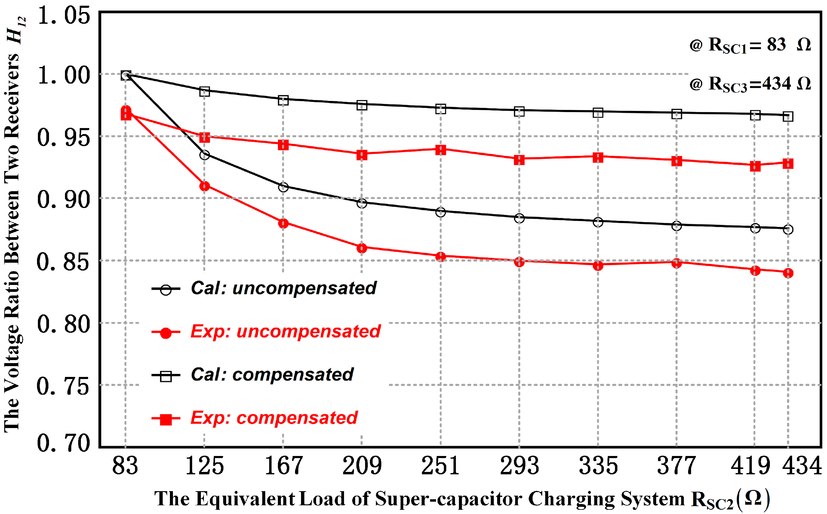
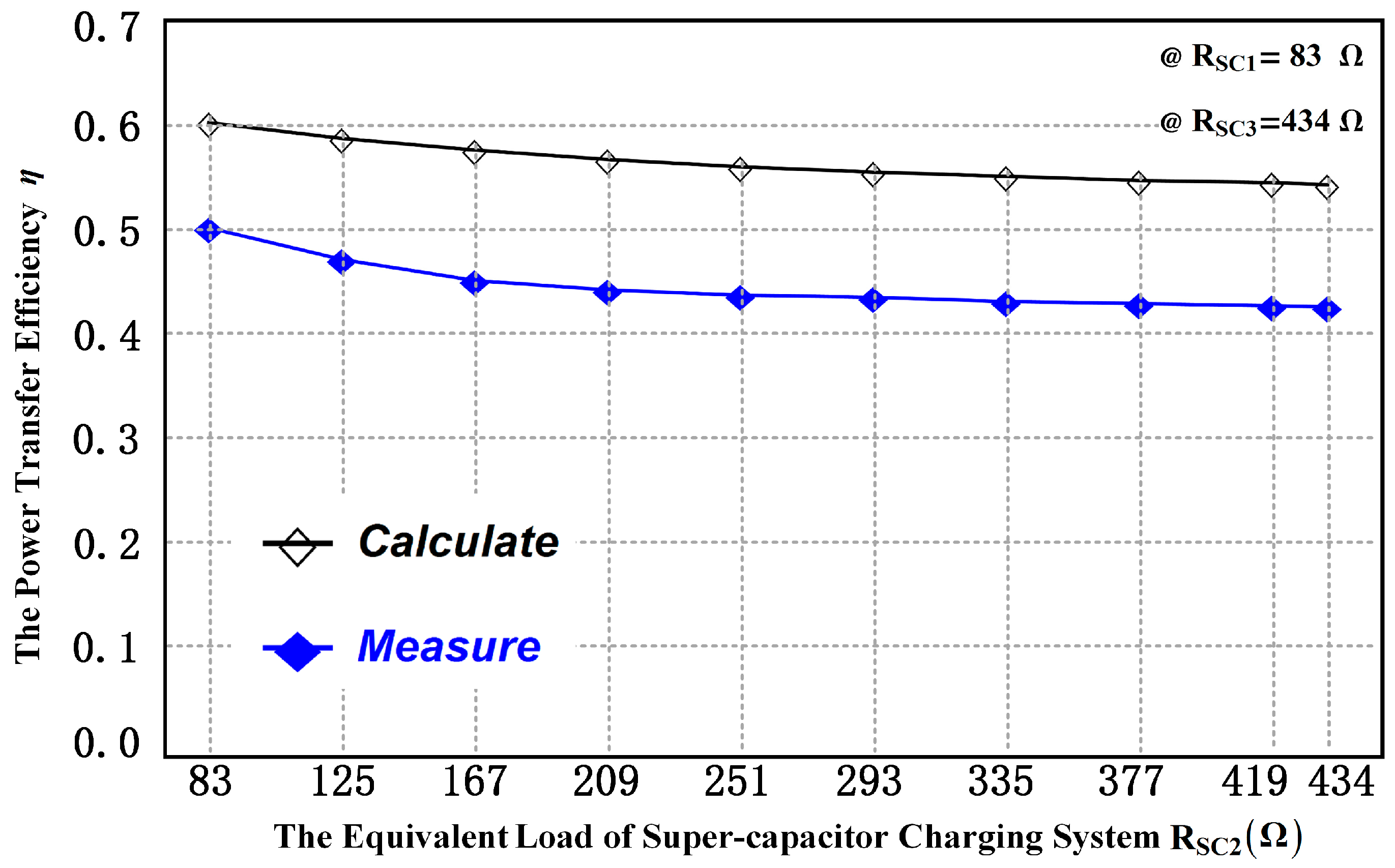
From the aforementioned review, it is envisaged that in practical applications each receiver must have a stable voltage for different underwater systems, and on that basis, the system needs to simultaneously achieve high efficiency. In this paper, a multiple-receiver ICPT system for mooring buoys is proposed, which is designed to realize the stable voltage and high efficiency of underwater systems by using series compensation for all loops based on mathematical derivation. In addition, for the prototype ICPT system with three receivers mounted on a 30 m mooring cable, the voltage division ratio between two arbitrary receivers is almost 1, while the power transfer efficiency can exceed 45%. The system proposed in this paper can be applied for measuring profile parameters in real-time, and will provide a reference for the development of multiple-receiver ICPT systems.
The rest of this paper is organized as follows: in
Section 2, a structure of the multiple-receiver ICPT system for mooring buoys is presented, and key parameters of this system are defined. In
Section 3, the double-receiver system model is analyzed in detail, and then calculated by Wolfram Mathematica to achieve load-independent voltage ratio and high efficiency. In
Section 4, the theoretical analysis is extended to an ICPT system for mooring buoys with
receivers. In
Section 5, an experimental prototype is established to verify the results of
Section 4. Finally,
Section 6 draws some conclusions about our findings.
2. System Structure
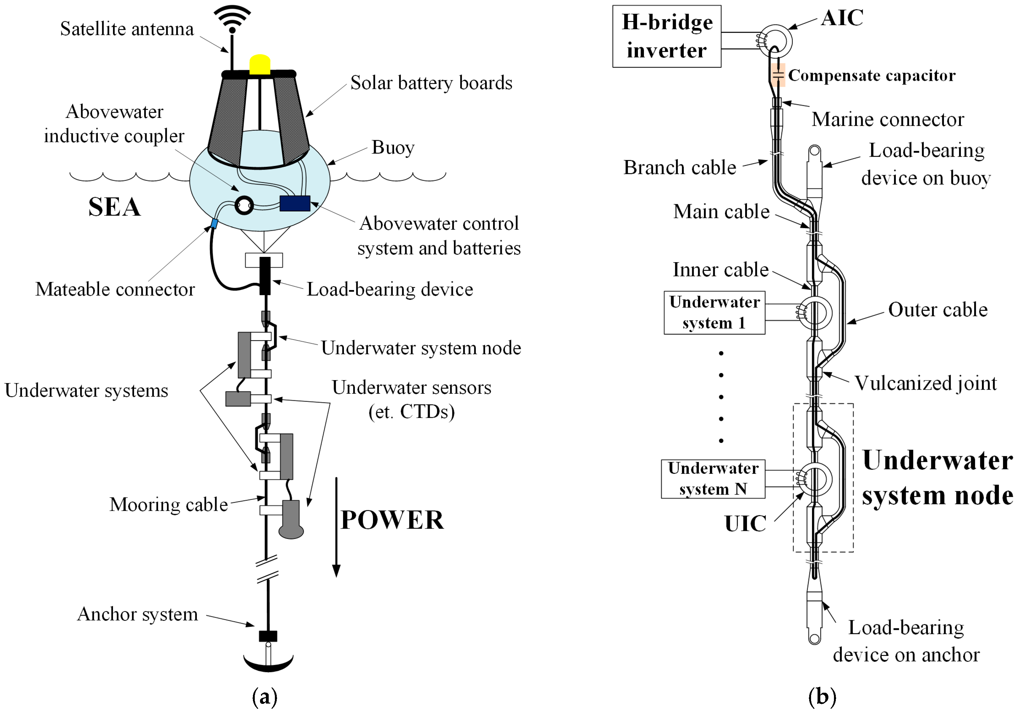
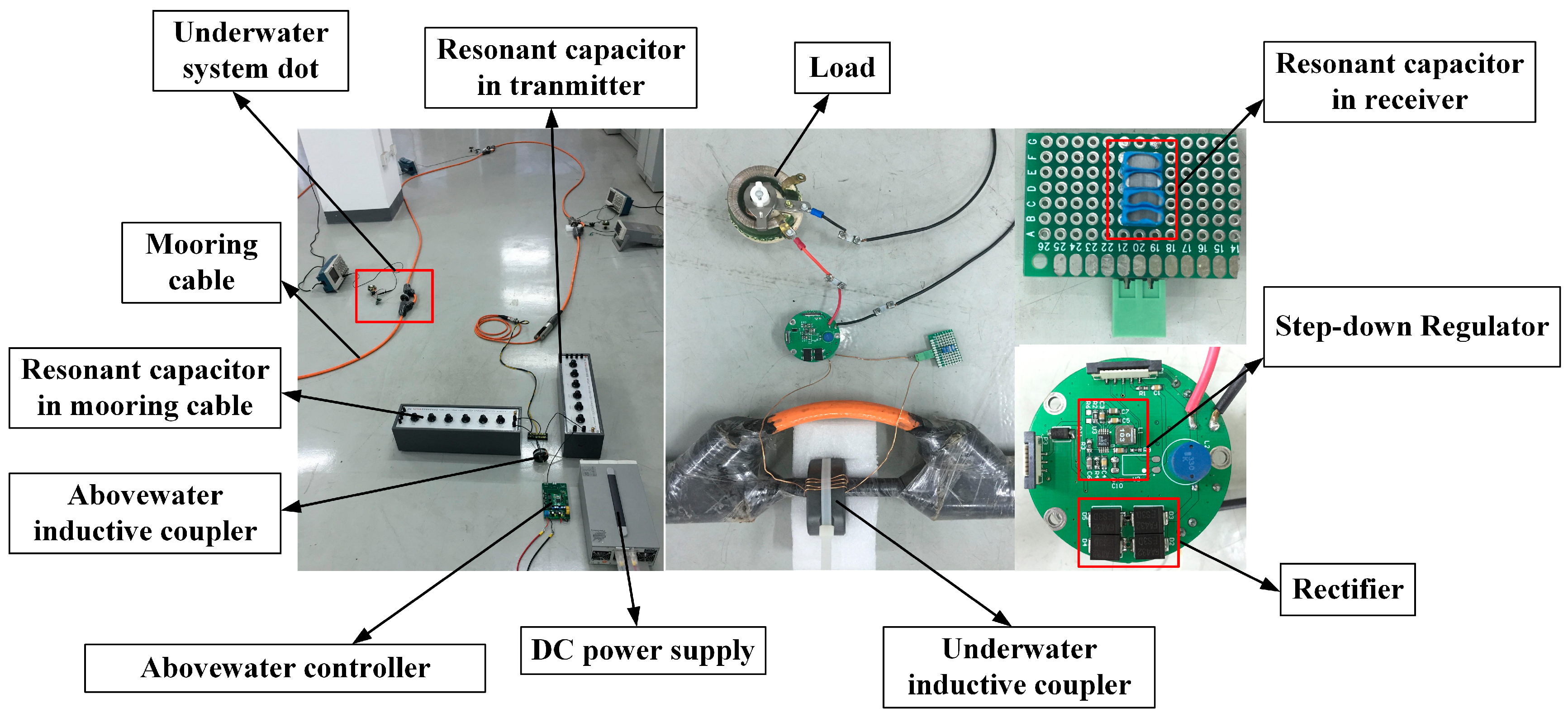
The composition of a multiple-receiver ICPT system for mooring buoys is shown in
Figure 1a. The power is converted by solar battery boards and stored in a lead-acid battery, which can provide 12 V/150 Ah electricity. The mooring cable, which fixes the buoy in a certain area with the help of an anchor system, acts as a power transmission cable. Underwater systems, which are mounted on the mooring cable, can get power from the lead-acid battery by using the mooring cable and inductive couplers.
Figure 1b reveals the design of the system circuit model with mooring cable. In this special ICPT system, the mooring cable can be divided into three sections: the secondary coil of the abovewater inductive coupler (AIC), the primary coil of underwater inductive couplers (UICs) and the main cable used for transmitting power between the AIC and UICs. The mooring cable is a closed cable as the branch cable is connected with the abovewater controller through the marine connector, and it is wrapped by a shielding layer. Therefore the self-inductance of the mooring cable is a constant and will not be affected by seawater ([
21], pp. 7–8). It is important to calculate the resonant capacitor in the resonant state. Moreover, we have measured the self-inductance of the mooring cable in the sea at different frequencies, and compared with that in the air. The results are listed in
Table 1. The number of underwater system nodes is determined by the specific application. Usually, the distance between any underwater system nodes is long (more than 3 m), and the mutual inductance between UICs can be ignored.
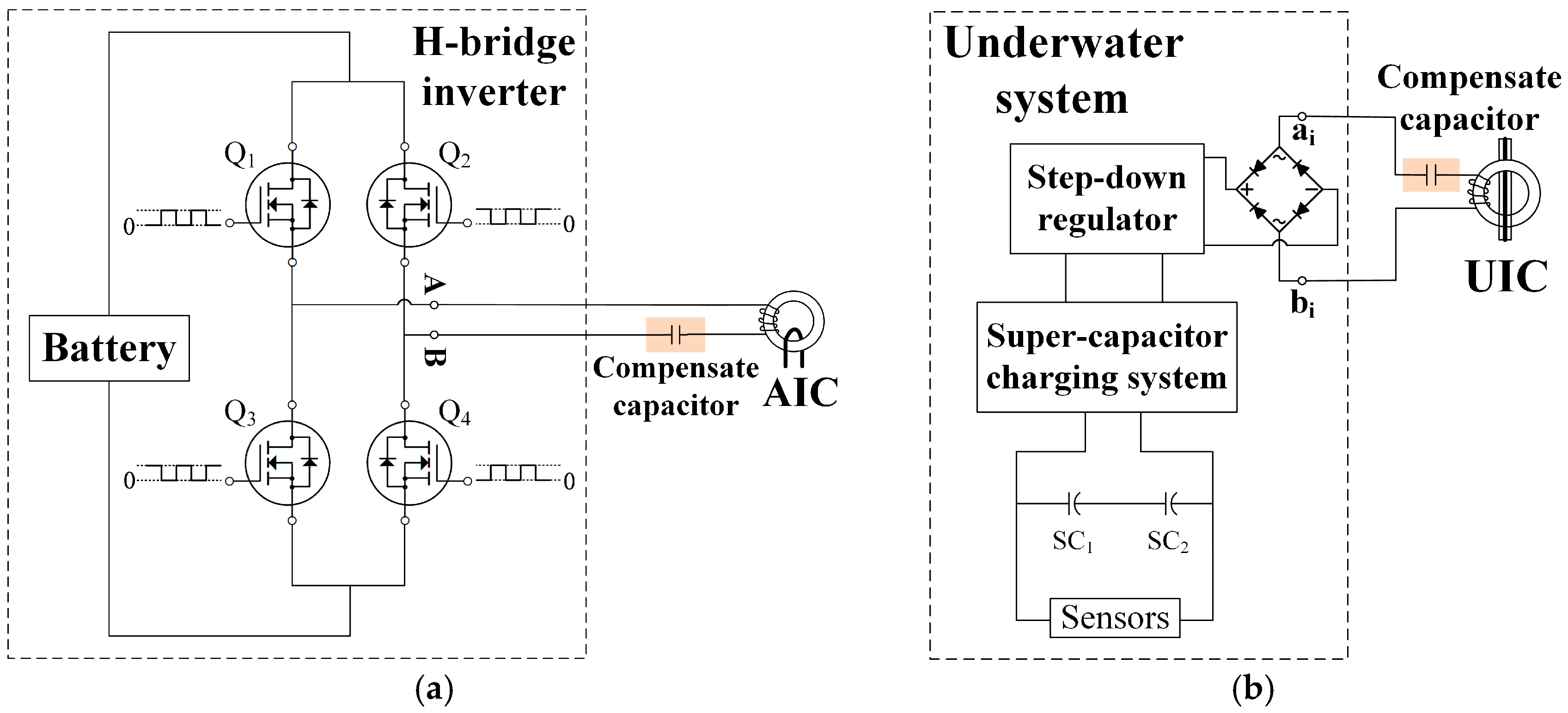
An H-bridge inverter is utilized to convert the DC power generated by the battery into a high-frequency rectangular wave. Four quality field effect transistors (QFETs) FQA38N30 (Fairchild Semiconductor, San Francisco, CA, USA) constitute the H-bridge structure as shown in
Figure 2a. Two complementary pulse width modulation (PWM) waves with dead band time are generated by the microcontroller unit, and the QFETs are driven through two driver chips IR2110 (Infineon, Neubiberg, Germany). Through the H-bridge inverter, the DC power can be inverted to rectangular wave with variable frequency. Based on Faraday’s law, a high frequency magnetic field is generated in the AIC, and the power is transmitted by the mooring cable. Through the vulcanized joints, the main cable is divided into inner cable and outer cable. UICs are mounted on the inner cable and underwater systems can obtain power from the mooring cable based on Faraday’s law as well. Finally, a full-bridge rectifier and a step-down regulator are applied to convert AC power to DC to charge the super-capacitors in each underwater system. Underwater sensors, such as conductivity-temperature-depth sensors (CTDs), can obtain power from super-capacitors and measure parameters at any time.
Figure 2b shows the composition of the underwater system. In general, a super-capacitor charging system can be regarded as a variable load with time. Considering the influence of step-down regulators and rectifiers [
22], the equivalent load resistance of underwater system
is:
where
is the duty-cycle of the step-down regulator, which is equal to 0.75 in this system.
is the equivalent resistance of super-capacitor charging system, the range of
is from 83 Ω to 434 Ω by experiments. From (1), the range of
is from 120 Ω to 625 Ω.
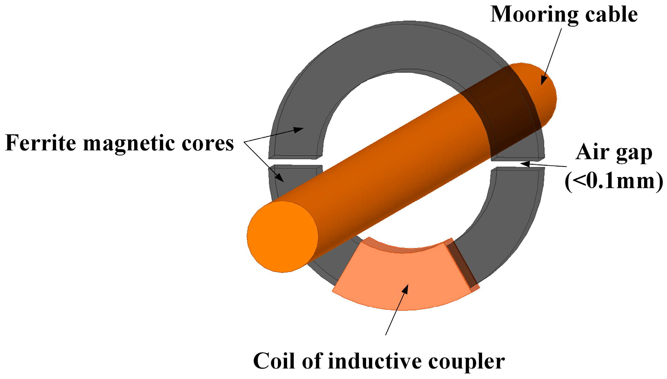
AIC and UICs have the same structure, which is shown in
Figure 3. A toroidal ferrite magnetic core is cut symmetrically in order to conveniently mount on the inner cable. The parameters of the inductive coupler are listed in
Table 2. Using a special sealing device, the inductive coupler is completely isolated from seawater, and the coupling coefficient is measured as 0.97.
In order to analyze the multiple-receiver ICPT system for mooring buoys, definitions of some key parameters are tabulated in
Table 3. The symbol
is the number of receivers in the range of 1 to
n.
3. Double-Receiver ICPT System for Mooring Buoy
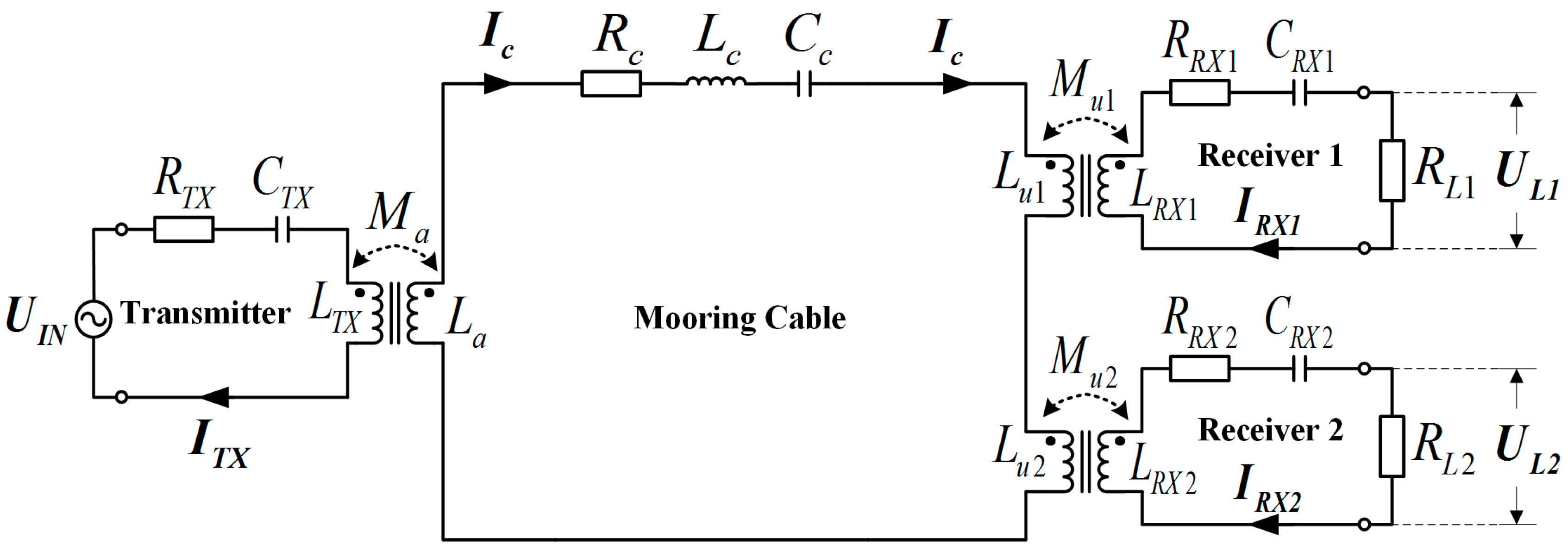
A model of double-receiver ICPT system for mooring buoy is shown in
Figure 4. It is divided into four parts: one transmitter (TX), one mooring cable, and two receivers (RX1 and RX2). Using one AIC and two UICs, TX, RX1 and RX2 are coupled to the mooring cable with mutual inductances of
,
and
respectively. The coupling coefficient between the AIC’s coils is:
and the coupling coefficient between the UICs’ coils is:
Since the distance between two receivers is sufficiently long, the mutual inductance between RX1 and RX2 can be ignored.
In
Figure 4,
is the input voltage with the frequency
between
and
shown in
Figure 2a.
is the angular frequency, which is equal to
;
and
are the voltage to the loads.
,
,
and
are the current of TX, mooring cable, RX1 and RX2 respectively;
and
are the gain of voltage and defined as
and
;
and
are the active power delivered to two equivalent loads
and
. Finally, the power transfer efficiency can be calculated as a ratio between the total active power received by equivalent loads and the apparent power supplied by the source [
23].
The equivalent impedance of each loop can be described as
, where
is the resistance and
is the reactance.
is the resistance of the coil, while the equivalent series resistance of the capacitor is ignored because it is generally small in network [
24]. Using
to substitute
,
and
, the circuit’s current
,
and
are contacted with the input voltage
employing by Kirchhoff’s voltage law (KVL):
where:
3.1. Compensate for Coils Inductance of Receivers
Solving (4) gives the relationship:
In the double-receiver ICPT system for mooring buoy, the UICs are the same, including magnetic cores and coils. Therefore, the parameters of each UIC are equal:
As shown in the
Figure 4 and Equation (7), the resistance
, and the reactance
. Normally, the resonant angular frequency and the normalized angular frequency of RX are defined as:
and, the equivalent impedance of coil in receivers:
According to the definition of
and
and hypothesize
, the voltage division ratio between two receivers can be obtained as:
In order to achieve the load-independent voltage ratio, an appropriate operating angular frequency will be chosen.
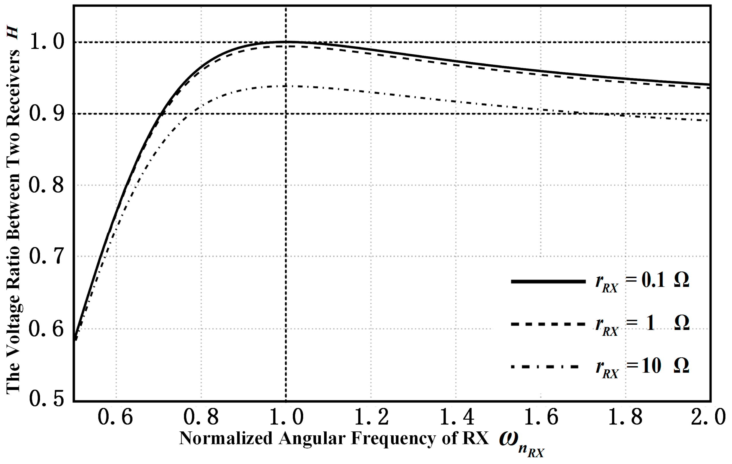
Parameters of receivers are talented in
Table 4. The voltage division ratio between two receivers
, which is a function of the normalized angular frequency of RX
is shown in
Figure 5. On the one hand, the voltage division ratio between two receivers is close to 1 when
. In other words, the operating angular frequency equals the resonant angular frequency of RX. That means the voltage to different equivalent loads in different receivers is nearly equivalent as the receiver’s coil work in the resonant state. On the other hand, the voltage division ratio between two receivers is closer to 1 as the resistance of coils decrease.
3.2. Compensate for Coils Inductance of Tranmitter and Mooring Cable
Ensuring that the voltage across the equivalent load is approximately equal by compensating for coils inductance of receivers, the most important characteristic of the ICPT system for mooring buoys is promoting the output power received by underwater systems and the power transfer efficiency, which are defined as:
where
means the conjugate of
. Solving (4) and
under the condition of
, the voltage to equivalent loads are obtained as:
where:
and the output power received by underwater systems and the power transfer efficiency can be described by following equation:
It can be observed that the output power
and the power transfer efficiency
are related to
and
. As definition from (17) and (18),
is a constant and
is function of the reactance of coil in transmitter
and of mooring cable
. When the inductive couplers are determined, parameters of coils in transmitter and receivers as well as mooring cable, such as the resistances (
,
,
,
) and the mutual inductances (
,
) are affirmative.
and
are expressed as follows:
Similarly, the resonant angular frequency and the normalized angular frequency in the transmitter and mooring cable are defined as:
and the reactance can be represented as:
According to (17)–(20), the output power and the power transfer efficiency can be written as:
where:
From (25)–(34),
and
are functions of two variables
and
as follows:
where
and
.
Since
can be adjusted easily in the system of a mooring buoy, a suitable input voltage can be chosen according to actual demand power since
. Therefore, the power transfer efficiency is attracting more attention in this situation. In order to achieve the maximum of the power transfer efficiency
, the method of getting the maximum is used as follows. Solving the equations:
Using (37) to get a stationary point
and obtain:
To check the point is whether the extreme point or not, the functions
,
and
are calculated. And then obtain
Obviously, all parameters are positive, so
as well as
. According to the necessary and sufficient condition of maximum value of two variable function, the stationary point
is the maximum point and
correspondingly ([
25], pp. 946–950).
Parameters of transmitter and mooring cable are tabulated in
Table 5.
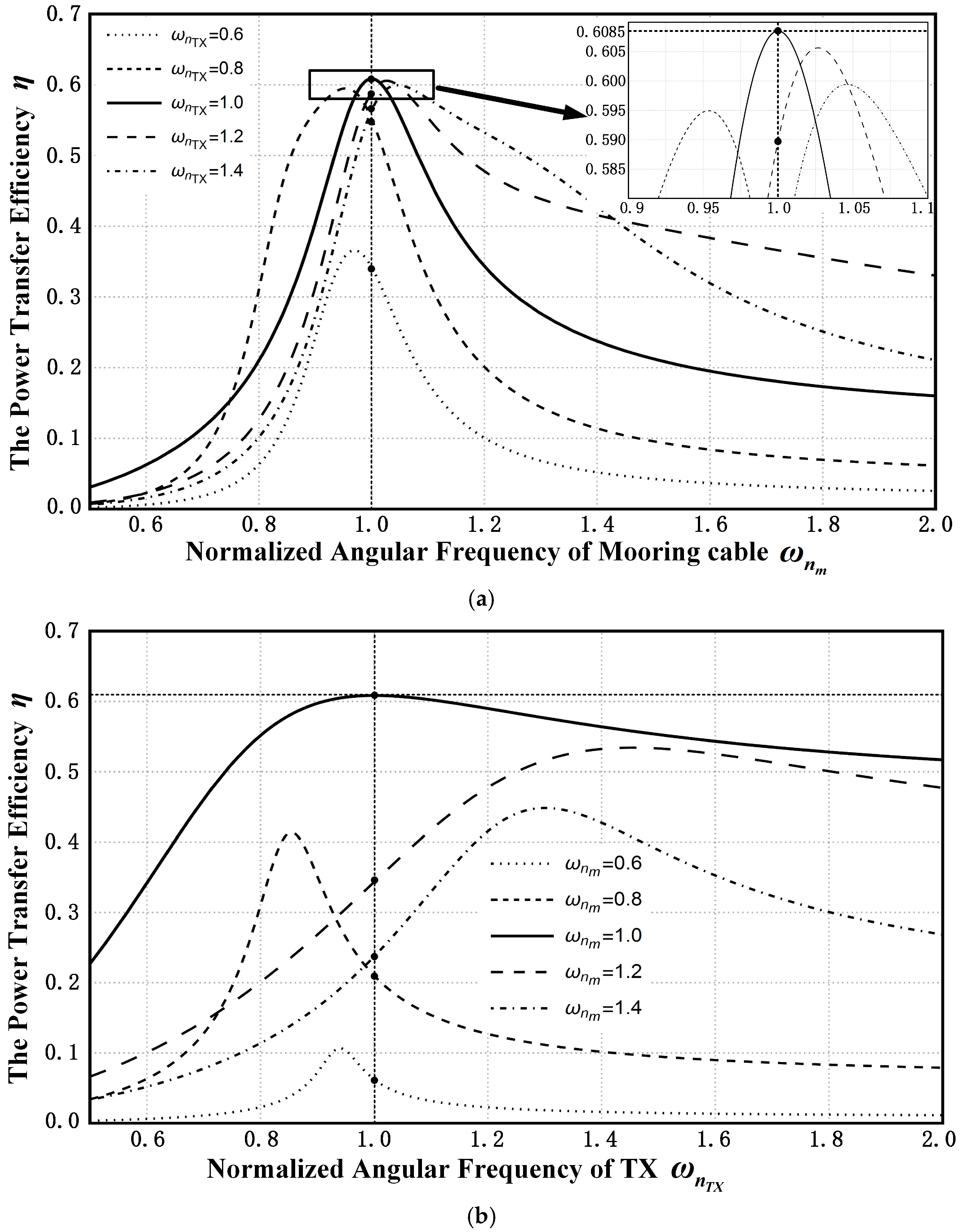
Figure 6 is drawn to verify the maximum point. On the one hand, the relationship between the power transfer efficiency and the normalized angular frequency of mooring cable is shown in
Figure 6a. For different
, the
can be obtained at different
correspondingly. Comparing these local maximum points for each curve, the absolute maximum point can be found as
and
and the maximum efficiency is 60.85%. On the other hand,
Figure 6b depicts the relationship between the power transfer efficiency and the normalized angular frequency of transmitter. This time,
is a discrete parameter while
take a continuous value from 0.5 to 2. It is clearly that the maximum
obtained at
and
as the same of
Figure 6a. Analyzing of these two graphs, efficiency has an absolute maximum at
and
. From (24),
in that condition, and the method of getting the maximum is verified. In addition, ensuring
is more important than
to achieve higher efficiency by comparing these two graphs.
4. Multiple-Receiver ICPT System for Mooring Buoy
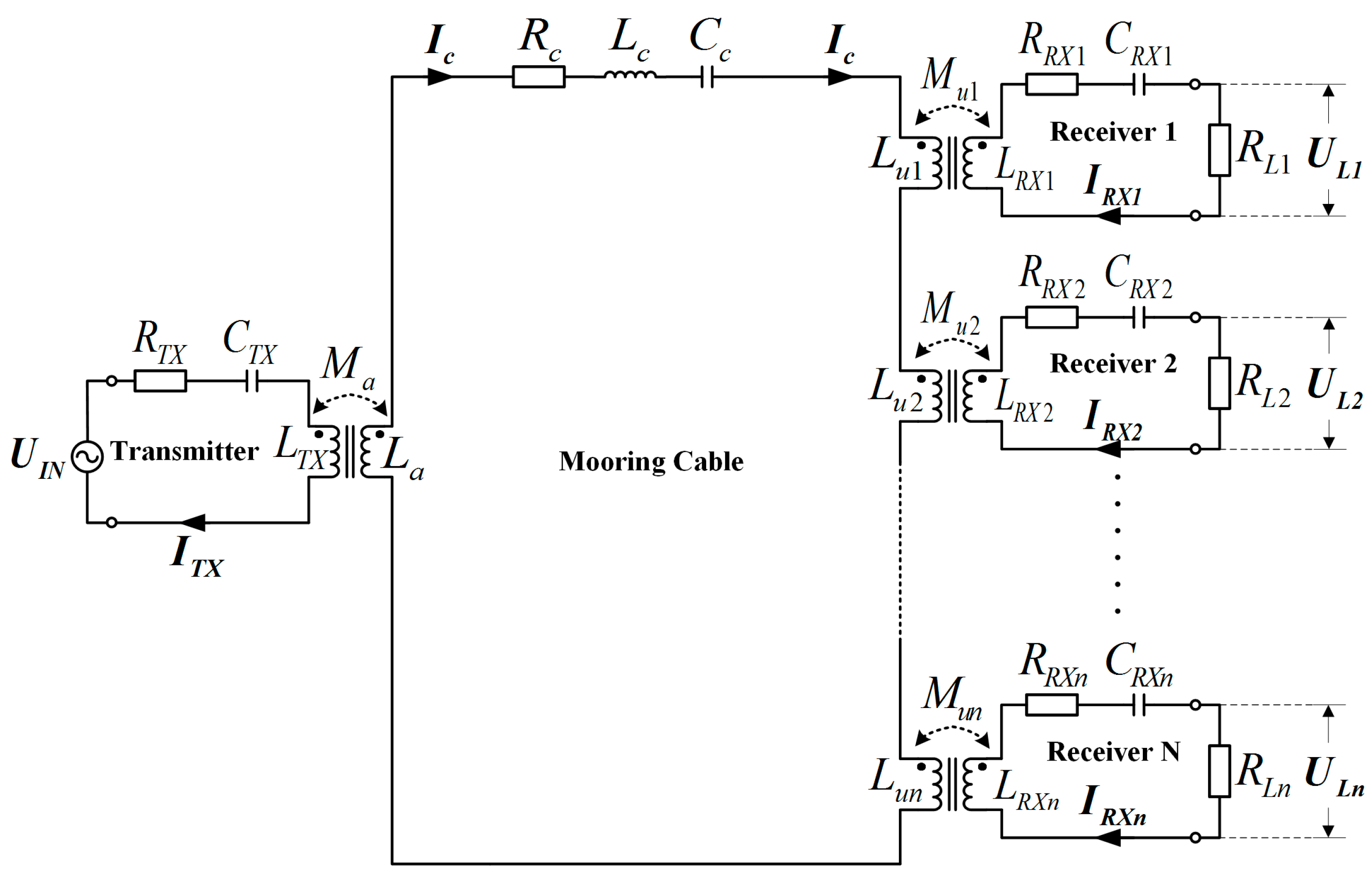
Here, the multiple-receiver ICPT system for a mooring buoy, which is similar to a two-receiver system, is shown as
Figure 7. In this model,
receivers are mounted on the mooring cable while the power is provided by one transmitter.
is the equivalent load resistant in receiver
,
as well as
and
are the parameters of receiver
. The mutual inductance for UICs is defined as
and they are identical in order to simplified analysis, while the coupling coefficient between inductive coupler’s coils are:
The KVL is applied to multiple-receiver system to get the voltage division ratio between two arbitrary receivers, the output power and the power transfer efficiency, where
and
.
Similarly, ensuring identical voltage to different loads in different receivers is the first task. From (44),
as
, where the resistances of coils are too small to the equivalent loads. In that case, the (42) can be simplified as:
where
is defined as the sum of the resistance of coils
and the resistance of equivalent loads
, for the range of
is from 1 to
. Based on (46), the voltage to equivalent loads is calculated as:
where:
And the output power and the power transfer efficiency are obtained:
Pay attention to this: when
, (47)–(51) are identical with (16)–(20). From (51),
is the function of
and
and can be described as:
where:
It is similar to (36). Based on the method of getting the maximum, circuits of the transmitter and the mooring cable are working at full resonance state, meaning
and
, the maximum power transfer efficiency can be obtained
Meanwhile, experiments are carried out in
Section 5 for three-receivers to verify the theory of the multiple-receiver ICPT system for mooring buoys.


