
Improvement of Transient Stability in a Hybrid Power Multi-System Using a Designed NIDC (Novel Intelligent Damping Controller)


Abstract
:1. Introduction
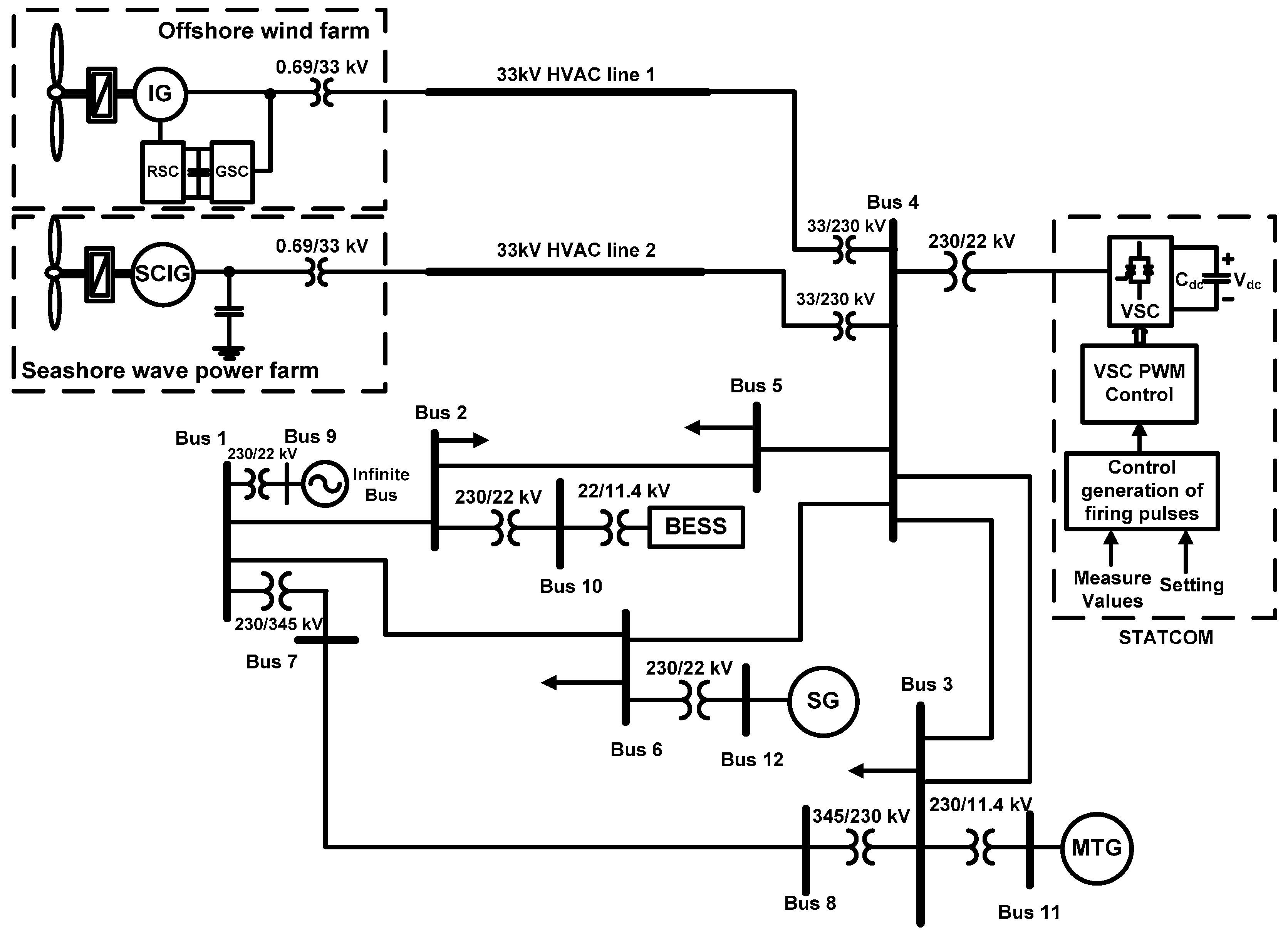
2. Analysis of System Models
2.1. Wind Turbine Characteristics
2.2. DFIG
2.3. Wells Turbine
2.4. BESS and MTG
2.5. MTG
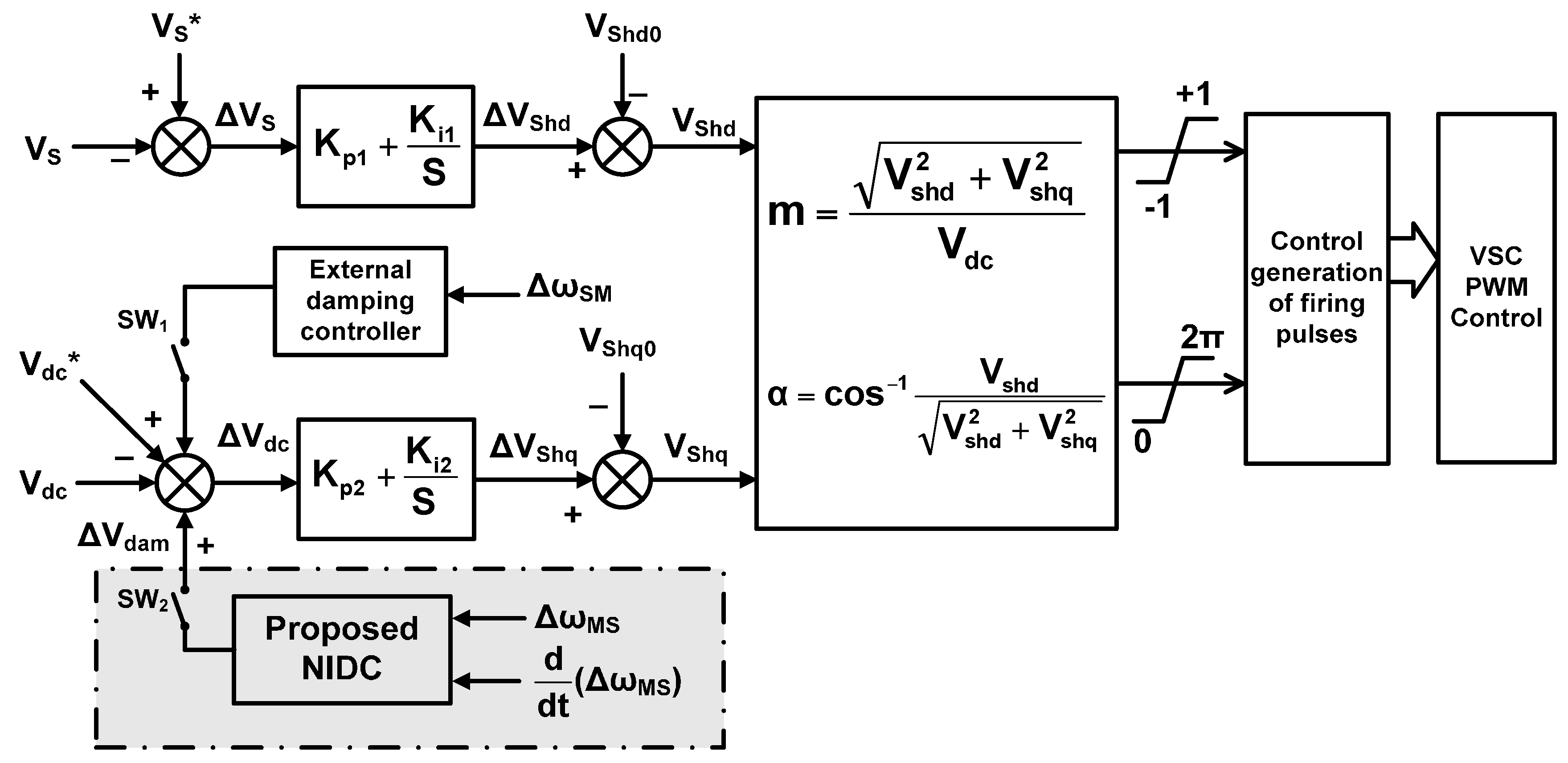
2.6. STATCOM
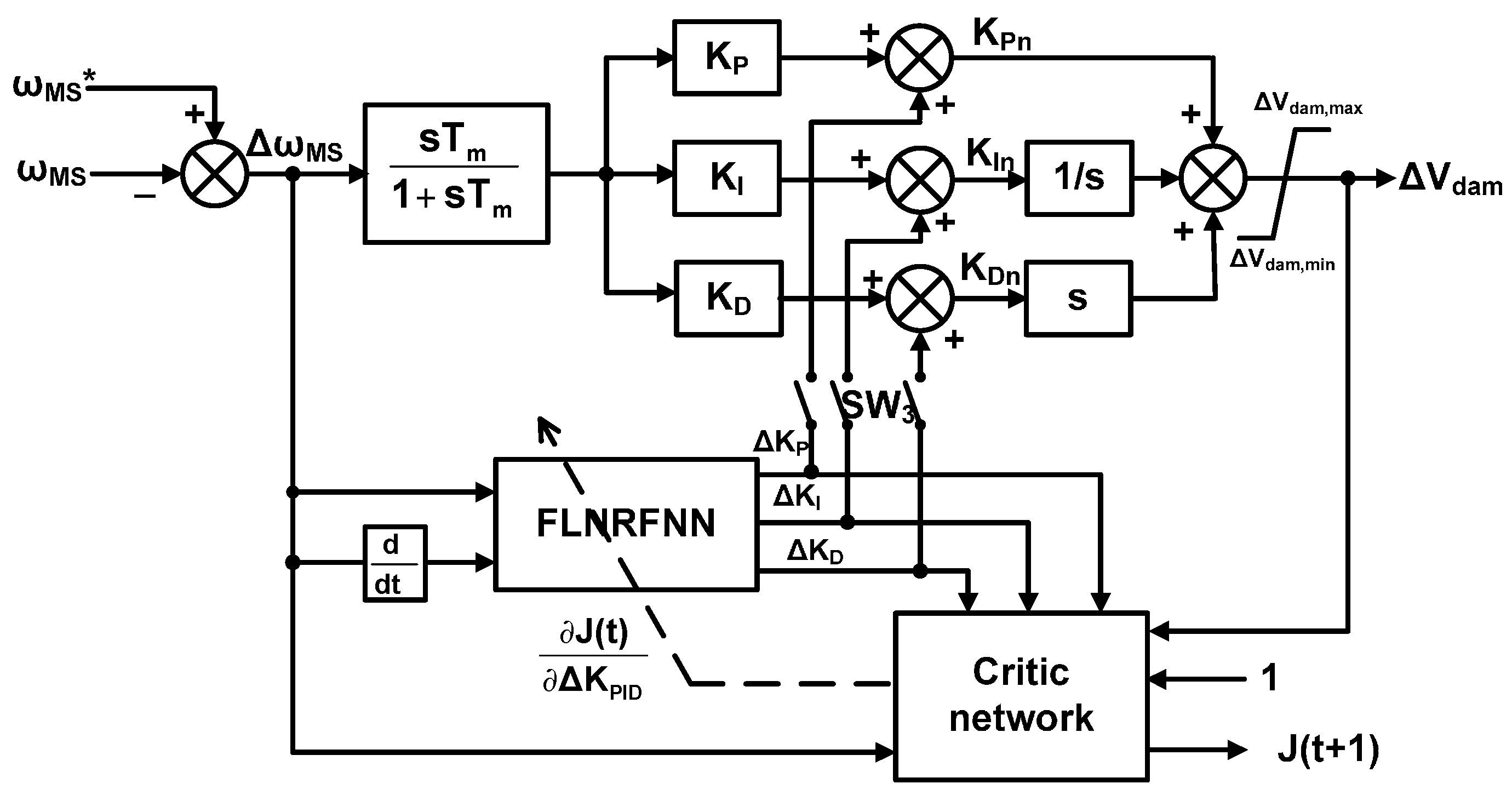
3. Design an NIDC for the STATCOM
3.1. PID Damping Controller
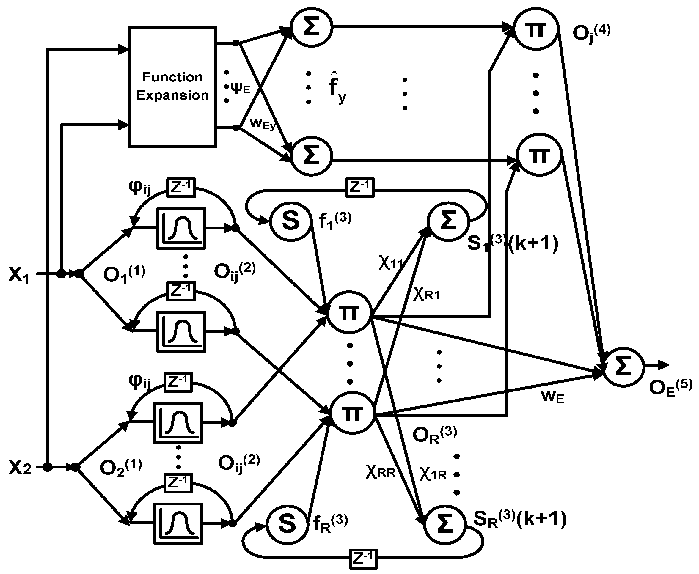
3.2. FLNFRNN
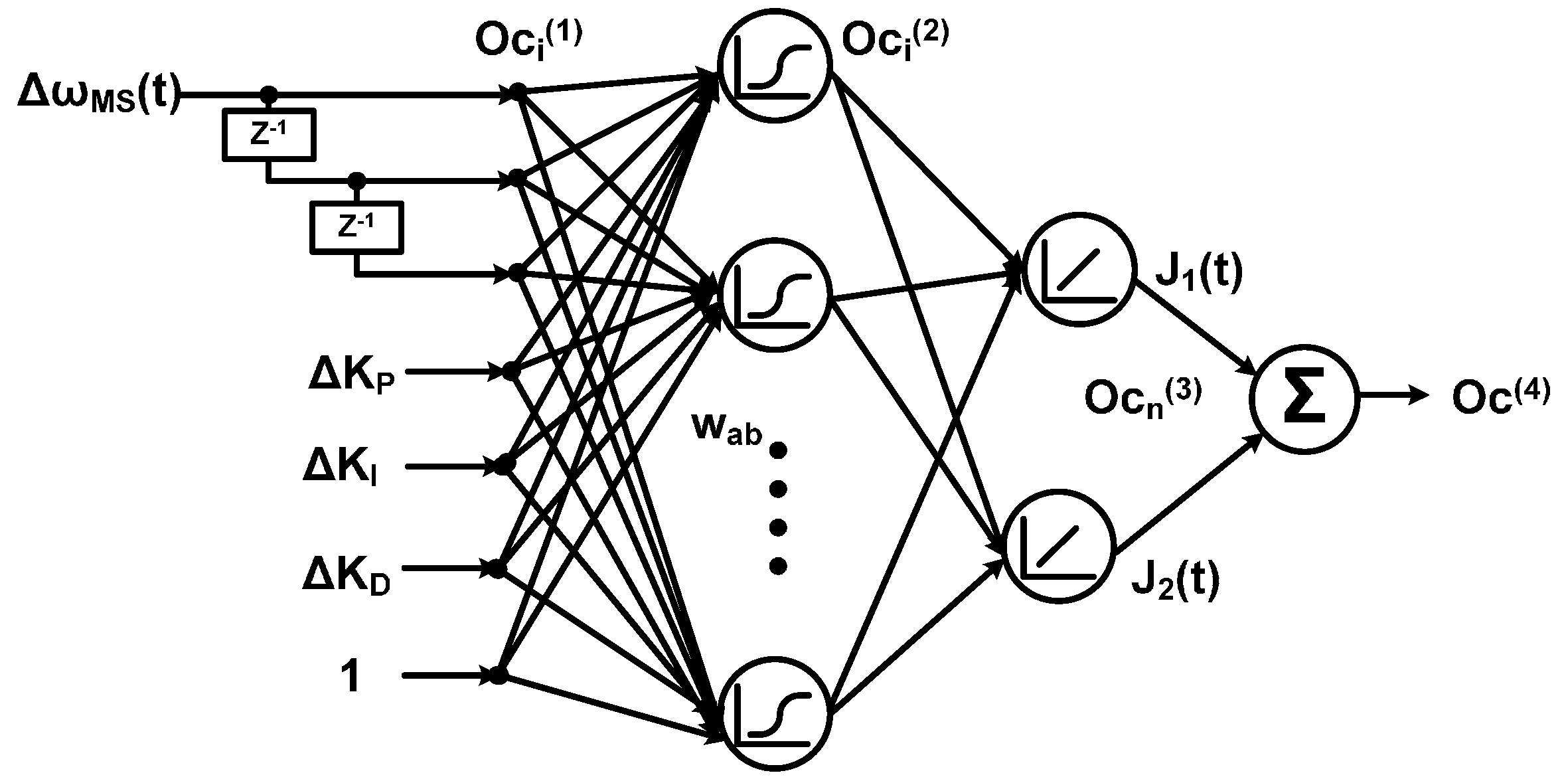
3.3. Adaptive Critic Network
3.4. The Training Process of FLNRFNN and Critic Network
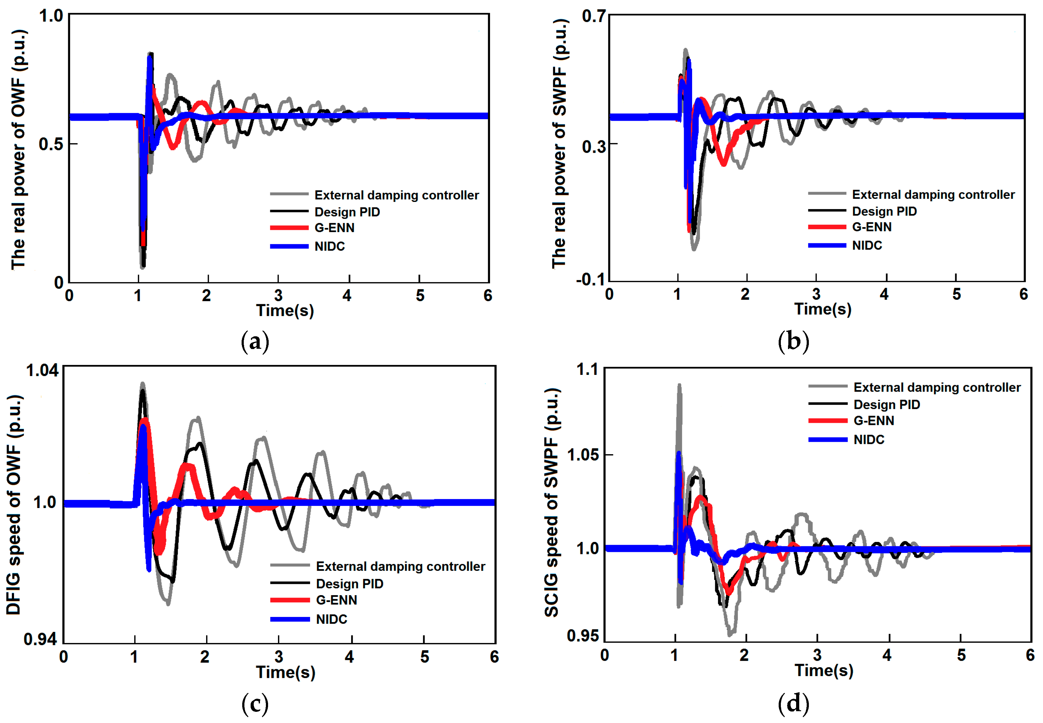
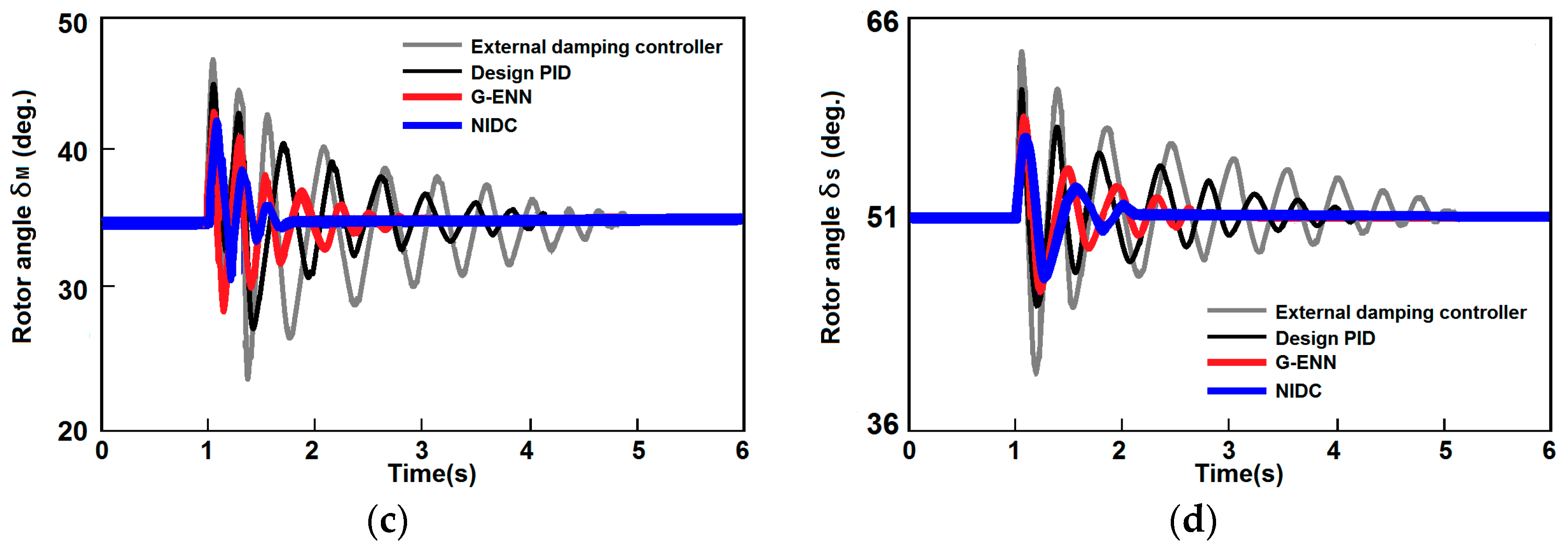
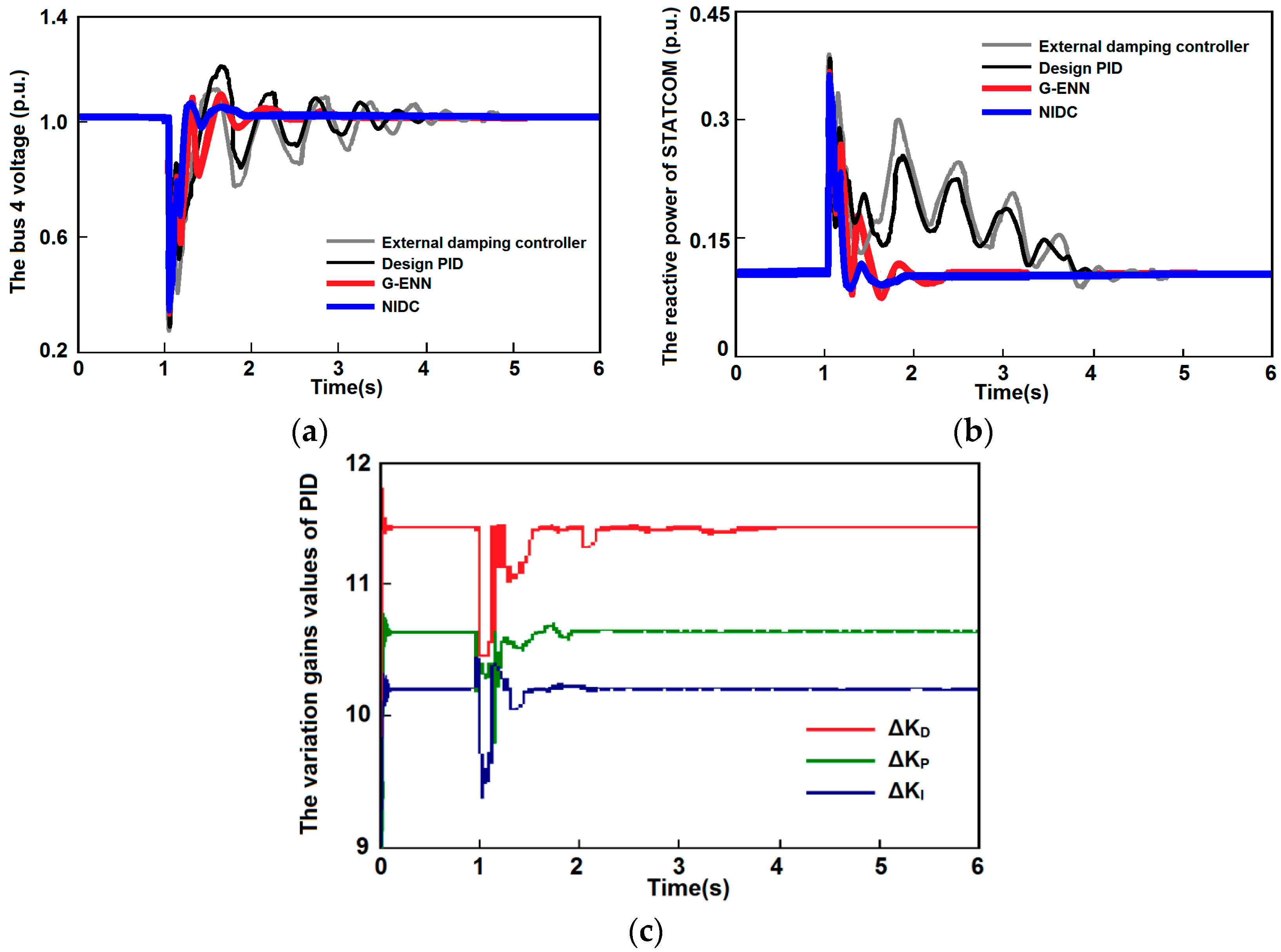
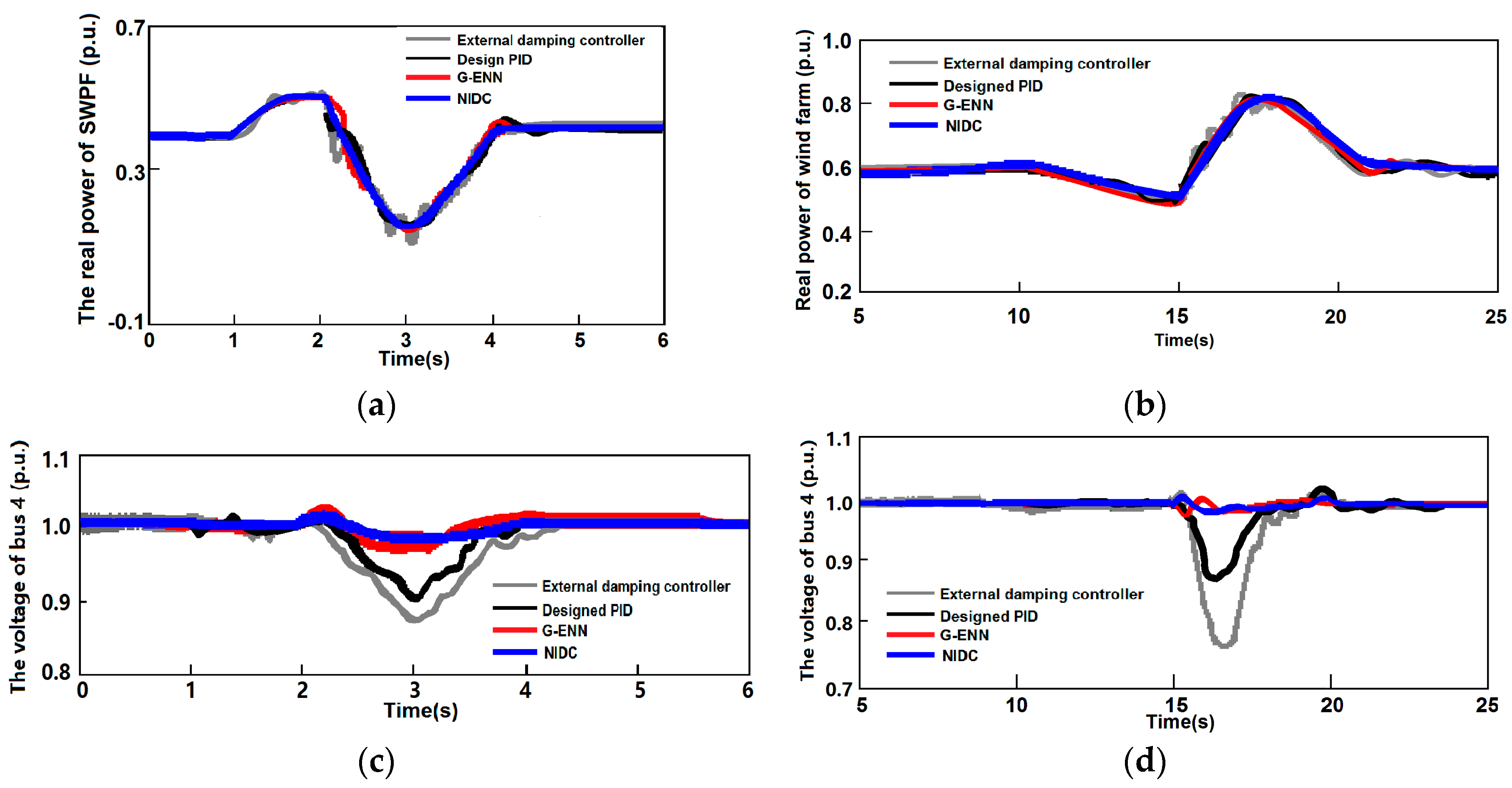
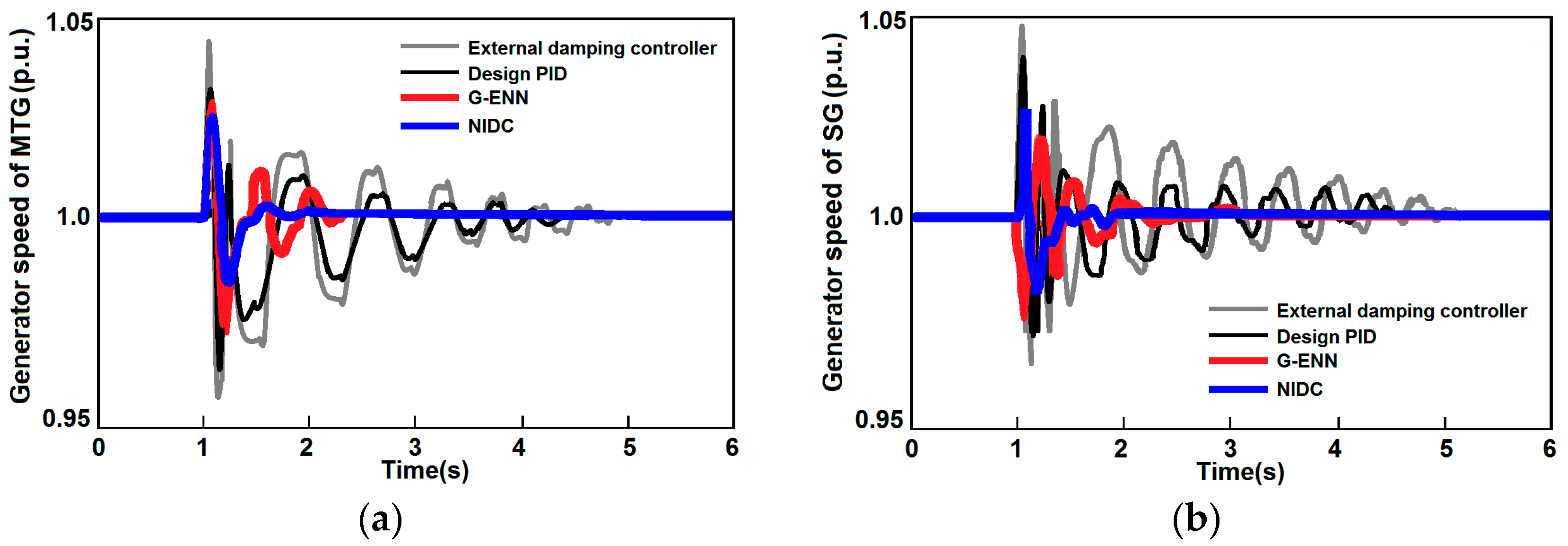
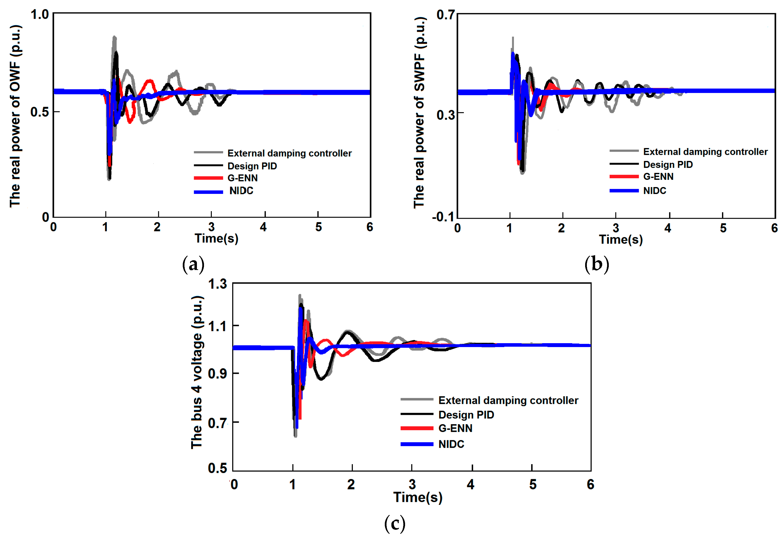
4. Case Studies and Simulation Results
5. Conclusions
Acknowledgments
Author Contributions
Conflicts of Interest
Nomenclature
| ρ | air density (kg/m3) |
| A | disk radius of the rotor blades (m2) |
| Vω | wind velocity (m/s) |
| Pm | output mechanical power of wind turbine |
| Cp | power coefficient, and is given as a nonlinear function of the |
| λ | tip speed ratio |
| turbine speed | |
| β | blade pitch angle |
| blade radius | |
| ωe | electrical angular frequency |
| Tm | mechanical torque |
| Te | electrical torque |
| np | number of poles |
| J | inertia moment of WTG |
| B | friction coefficient of the generator |
| V | axial flow velocity |
| K | coefficient of Wells turbine |
| CT | Wells turbine torque constant coefficients |
| IB | equivalent short-circuit current of BESS |
| ZB | series equivalent impedance of BESS |
| VBESS | terminal voltage of BESS |
| XOWF | state vector of the electric system of OWF |
| XSWPF | state vector of the electric system of SWPF |
| Xtur | state vector of wind and Wells turbine systems |
| XSTATCOM | state vector of STATCOM |
| VS* | reference signal for the bus voltage |
| Vdc* | reference signals for dc link voltage |
| VS | bus voltage |
| δS | phase angle of bus voltage |
| Rp | resistance of the STATCOM |
| idcd | d axis current values of STATCOM |
| idcq | q axis current values of STATCOM |
| ΔKPID | variation gains values |
| outer product term | |
| wEy | connective weight |
| ψE | function expansion output |
| θ | basic functions |
| Tm | time constant of the washout filter |
| mij | Mean |
| σij | Standard Deviation (STD) |
| E | error function |
| m | modulation index of PWM |
| α | phase shift of PWM |
| Δ | generator speed deviation |
| λ1–λ21 | complex eigenvalues |
| ij | i-term input variable in the j-term |
| J*(t) | reference value of the cost-to-go function |
| U(t) | utility function |
| discount factor (0~1) |
Appendix A
References
- Waldner, M.; Erlich, I. Variable speed wind turbines based on electromechanical differential systems. IEEE Trans. Energy Convers. 2014, 29, 101–109. [Google Scholar] [CrossRef]
- Cashman, D.P. Electrical Machine Characterisation and Analysis for Renewable Energy Applications. Ph.D. Thesis, University College Cork, Cork, Ireland, 2010. [Google Scholar]
- Clément, A.; McCullen, P.; Falcão, A.; Fiorentino, A.; Gardner, F.; Hammarlund, K.; Lemonis, G.; Lewis, T.; Nielsen, K.; Petroncini, S.; et al. Wave energy utilisation in Europe: Current status and perspectives. Renew. Sustain. Energy Rev. 2002, 6, 405–431. [Google Scholar] [CrossRef]
- Ou, T.C.; Tsao, T.P.; Lin, W.M.; Hong, C.M.; Lu, K.H.; Tu, C.S. A novel power flow analysis for microgrid distribution system. In Proceedings of the IEEE Conference on Industrial Electronics and Applications (ICIEA), Melbourne, Australia, 19–21 June 2013; pp. 1550–1555. [Google Scholar]
- Ou, T.C.; Hong, C.M. Dynamic operation and control of microgrid hybrid power systems. Energy 2014, 66, 314–323. [Google Scholar] [CrossRef]
- Ou, T.C. Ground fault current analysis with a direct building algorithm for microgrid distribution. Int. J. Electr. Power Energy Syst. 2013, 53, 867–875. [Google Scholar] [CrossRef]
- Elsamahy, M.; Faried, S.O.; Sidhu, T. Voltage support control strategies for static synchronous compensators under unbalanced voltage sags. IEEE Trans. Ind. Electron. 2014, 61, 808–820. [Google Scholar]
- Chen, W.L.; Liang, W.G.; Gau, H.S. Design of a mode decoupling STATCOM for voltage control of wind-driven induction generator systems. IEEE Trans. Power Deliv. 2010, 25, 1758–1767. [Google Scholar] [CrossRef]
- Hong, C.M.; Ou, T.C.; Lu, K.H. Development of intelligent MPPT (maximum power point tracking) control for a grid-connected hybrid power generation system. Energy 2013, 50, 270–279. [Google Scholar] [CrossRef]
- Fan, L.; Miao, Z. Mitigating SSR using DFIG-based wind generation. IEEE Trans. Sustain. Energy 2012, 3, 349–358. [Google Scholar] [CrossRef]
- Hong, Y.Y.; Luo, Y.F. Optimal VAR control considering wind farms using probabilistic load-flow and gray-based genetic algorithms. IEEE Trans. Power Deliv. 2009, 24, 1441–1449. [Google Scholar] [CrossRef]
- Mohagheghi, S.; Venayagamoorthy, G.K.; Harley, R.G. Optimal neuro-fuzzy external controller for a statcom in the 12-bus benchmark power system. IEEE Trans. Power Deliv. 2007, 22, 2548–2558. [Google Scholar] [CrossRef]
- Lin, W.M.; Hong, C.M.; Huang, C.H.; Ou, T.C. Hybrid control of a wind induction generator based on grey–elman neural network. IEEE Trans. Control Syst. Technol. 2013, 21, 2367–2373. [Google Scholar] [CrossRef]
- Lin, F.J.; Teng, L.T.; Lin, J.W.; Chen, S.Y. Recurrent functional link based fuzzy neural network controlled induction-generator system using improved particle swarm optimization. IEEE Trans. Ind. Electron. 2009, 56, 1557–1577. [Google Scholar]
- Toh, K.A.; Yau, W.Y. Fingerprint and speaker verification decisions fusion using a functional link network. IEEE Trans. Syst. Man Cybern. C 2005, 35, 357–370. [Google Scholar] [CrossRef]
- Lin, Y.Y.; Chang, J.Y.; Lin, C.T. Identification and prediction of dynamic systems using an interactively recurrent self-evolving fuzzy neural network. IEEE Trans. Neural Netw. Learn. Syst. 2012, 24, 310–321. [Google Scholar] [CrossRef] [PubMed]
- Du, Y.; Wu, Q.; Jiang, C.; Wen, J. Adaptive functional link network control of near-space vehicles with dynamical uncertainties. J. Syst. Eng. Electron. 2012, 21, 868–876. [Google Scholar] [CrossRef]
- Tang, Y.; Ju, P.; He, H.; Chuan, Q.; Feng, W. Optimized control of DFIG-based wind generation using sensitivity analysis and particle swarm optimization. IEEE Trans. Smart Grid 2013, 4, 509–520. [Google Scholar] [CrossRef]
- Ou, T.C. A novel unsymmetrical faults analysis for microgrid distribution systems. Int. J. Electr. Power Energy Syst. 2012, 43, 1017–1024. [Google Scholar] [CrossRef]
- Pai, F.S.; Huang, S.J. Design and operation of power converter for micro turbine powered distributed generator with capacity expansion capability. IEEE Trans. Energy Convers. 2008, 21, 110–118. [Google Scholar]
- Ray, S.; Venayagamoorthy, G.K. Wide-area signal-based optimal neurocontroller for a UPFC. IEEE Trans. Power Deliv. 2008, 2, 1597–1605. [Google Scholar] [CrossRef]
- Xu, X.; Hou, Z.; Lian, C. Online learning control using adaptive critic designs with sparse kernel machines. IEEE Trans. Neural Netw. Learn. Syst. 2013, 24, 762–775. [Google Scholar] [PubMed]
- Farrag, M.E.A.; Putrus, G.A. Design of an adaptive neurofuzzy inference control system for the unified power-flow controller. IEEE Trans. Power Deliv. 2012, 27, 53–61. [Google Scholar] [CrossRef]
- Lin, W.M.; Hong, C.M.; Ou, T.C.; Chiu, T.M. Hybrid intelligent control of PMSG wind generation system using pitch angle control with RBFN. Energy Convers. Manag. 2011, 52, 1244–1251. [Google Scholar] [CrossRef]
- Mitra, P.; Venayagamoorthy, G.K.; Corzine, K.A. SmartPark as a virtual STATCOM. IEEE Trans. Smart Grid 2011, 2, 445–455. [Google Scholar] [CrossRef]
- Lin, W.M.; Ou, T.C. Unbalanced distribution network fault analysis with hybrid compensation. IET Gener. Transm. Distrib. 2011, 5, 92–100. [Google Scholar] [CrossRef]


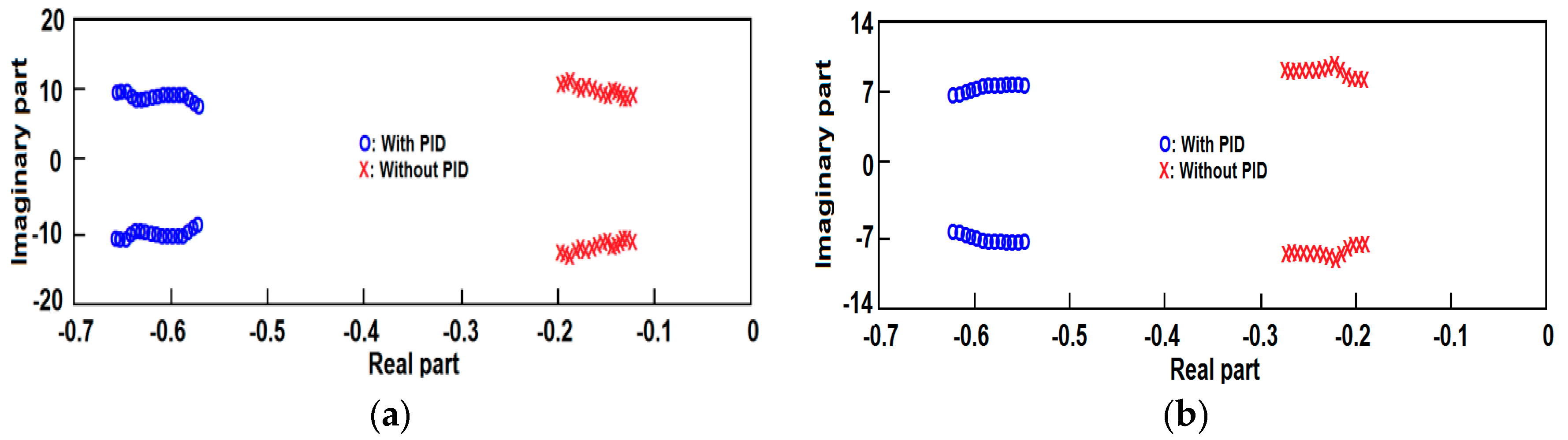
| Eigenvalues | Hybrid System without OWF, SWPF and STATCOM | Hybrid System with OWF, SWPF and STATCOM without PID | Hybrid System with OWF, SWPF and STATCOM with Designed PID |
|---|---|---|---|
| λ1 | −0.918 ± j18.788 | −1.122 ± j19.683 | −1.122 ± j19.683 |
| λ2 | −28.794, −5.426 | −31.526, −6.632 | −31.531, −5.766 |
| λ3 | −0.180 ± j9.366 | −0.193 ± j10.407 | −0.651 ± j9.90 |
| λ4 | −5.454 ± j8.244 | −5.713 ± j8.637 | −5.945 ± j8.512 |
| λ5 | −0.178 ± j7.017 | −0.186 ± j7.351 | −0.550 ± j7.810 |
| λ6 | −0.467 ± j0.022 | −0.490 ± j0.071 | −0.437 ± j0.682 |
| λ7 | −0.416 ± j0.634 | −0.436 ± j0.6054 | −0.393 ± j0.321 |
| λ8 | −0.395 ± j0.416 | −0.414 ± j0.435 | −0.601 ± j0.834 |
| λ9 | −4.192, −3.387 | −4.392, −3.548 | −31.531, −5.766 |
| λ10 | −0.806 ± j9895.182 | −0.806 ± j9895.182 | |
| λ11 | −47.9644 ± j1203.51 | −47.9644 ± j1203.51 | |
| λ12 | −108.48, −100 | −108.48, −100 | |
| λ13 | −25.6377 ± j408.012 | −25.6377 ± j408.012 | |
| λ14 | −16.7684 ± j412.742 | −16.7684 ± j412.742 | |
| λ16 | −1.184, −0.309 | −1.184, −1.781 | |
| λ17 | −109.710, −110.132 | 110.022, −109.343 | |
| λ18 | −0.344 ± j0.596 | −0.3641 ± j0.202 | |
| λ19 | −0.281 | −0.281 | |
| λ20 | −2.354 ± j3.74 | −2.354 ± j3.74 | |
| λ21 | −2.024 ± j1.023 | −2.001 ± j1.109 |
© 2017 by the authors. Licensee MDPI, Basel, Switzerland. This article is an open access article distributed under the terms and conditions of the Creative Commons Attribution (CC BY) license (http://creativecommons.org/licenses/by/4.0/).
Share and Cite
Ou, T.-C.; Lu, K.-H.; Huang, C.-J. Improvement of Transient Stability in a Hybrid Power Multi-System Using a Designed NIDC (Novel Intelligent Damping Controller). Energies 2017, 10, 488. https://doi.org/10.3390/en10040488
Ou T-C, Lu K-H, Huang C-J. Improvement of Transient Stability in a Hybrid Power Multi-System Using a Designed NIDC (Novel Intelligent Damping Controller). Energies. 2017; 10(4):488. https://doi.org/10.3390/en10040488
Chicago/Turabian StyleOu, Ting-Chia, Kai-Hung Lu, and Chiou-Jye Huang. 2017. "Improvement of Transient Stability in a Hybrid Power Multi-System Using a Designed NIDC (Novel Intelligent Damping Controller)" Energies 10, no. 4: 488. https://doi.org/10.3390/en10040488
APA StyleOu, T.-C., Lu, K.-H., & Huang, C.-J. (2017). Improvement of Transient Stability in a Hybrid Power Multi-System Using a Designed NIDC (Novel Intelligent Damping Controller). Energies, 10(4), 488. https://doi.org/10.3390/en10040488