
A Novel Caving Model of Overburden Strata Movement Induced by Coal Mining


1
State Key Laboratory of Coal Resource and Safe Mining, China University of Mining & Technology, Beijing 100083, China
2
100083, China
*
Author to whom correspondence should be addressed.
Energies 2017, 10(4), 476; https://doi.org/10.3390/en10040476
Submission received: 20 December 2016
/
Revised: 28 March 2017
/
Accepted: 29 March 2017
/
Published: 1 April 2017
Abstract
:The broken pattern of the overburden strata induced by mining has a non-ignorable effect on overlying strata movement, failure, and safety in mining production. To study the caving pattern of overlying strata and determine the calculation method of fracture pathway parameters due to roof caving induced by coal mining, the trapezoidal broken models were developed to explain and prevent water leakage, and even water inrush, during the mining process. By incorporating the variation of the volume expansion coefficient, a connection among the parameters of the fracture pathways and fracture angles, face width, and mining height could be established, which shows that the larger the degree of the fracture angle is, the smaller the value of the volume expansion coefficient and face width is with a relatively larger mining height. This relationship was also used to determine the eventual evolution configuration of the trapezoidal broken model. The presented approaches may help us to better understand the movement of overburden strata and provide an idea to help settle conflicts related to fracture space calculations induced by coal mining.
1. Introduction
The current increase in energy needs is mainly driven by the increasing world population and industrialization [1,2,3,4,5,6,7,8,9,10,11]. Severe conflicts of interest are especially noteworthy regarding human life and the exploitation of energy resources [12,13,14,15,16,17,18,19,20,21,22,23,24]. Exploitation activities inevitably cause ground subsidence, water loss, building damage, and a series of other problems, especially in some eco-environmental fragile areas [3,25,26,27,28,29,30,31,32,33,34,35]. China, one of the energy giants, uses coal as its main source of energy, with coal production and consumption accounting for approximately 77% and 65% of the total national energy consumption, respectively [8,36,37,38,39,40,41]. Among the 96 state-owned key coal mines, 71% are in water-shortage mining areas. One of the major coal mining areas, Northwest China, including Inner Mongolia, Shanxi, and Ningxia, is an arid to semi-arid area and a vulnerable eco-geological environment [19,21,42,43]. In those places, water resources are extremely scarce, and its protection is of vital importance.
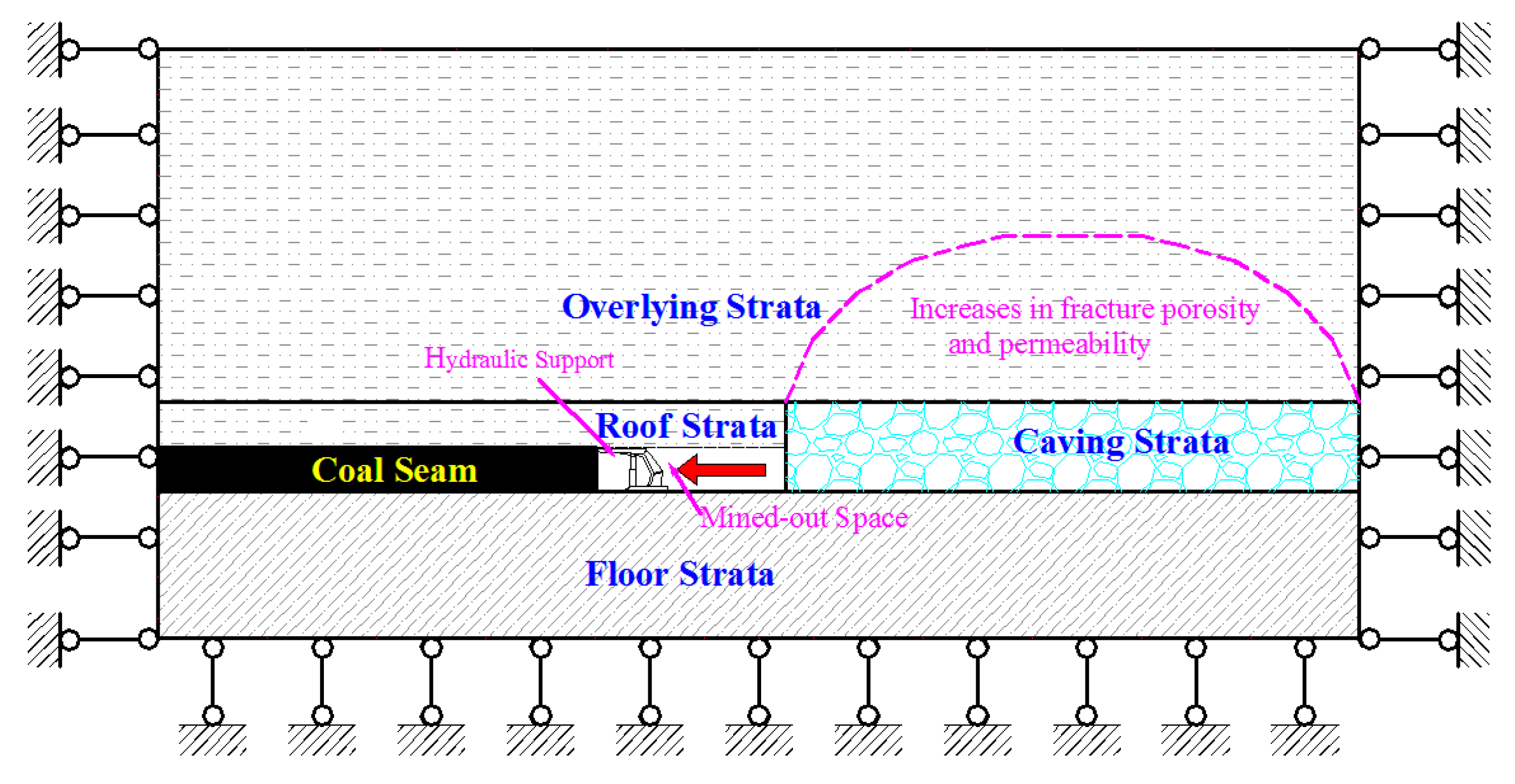
A variety of coal mining methods such as longwall mining, top slicing mining, sublevel caving mining, room-and-pillar mining, and backfill mining are widely used across the world [14,40]. Among these methods, longwall mining has the characteristics of safety, high efficiency, and high yield and is the preferred method of underground coal extraction. As can be seen in Figure 1, the process of mining involves the total exploitation of large, rectangular panels of coal several kilometers long and hundreds of kilometers wide, leaving only a movable hydraulic support behind to support the roof strata and further leading to land and strata subsidence and the hydro-geomechanical response of the overlying aquifers [4,5,15]. The redistribution of the overburden stress regime caused by longwall mining brings about general increases in fracture porosity and permeability owing to the development of fractures, joints, and bedding separations, resulting in the disruption of the natural groundwater flow system to a great extent [12,15,16,44].
Currently, a variety of methods, ranging from analytical methods and field experiments to numerical and physical simulation, have been used that mainly focus on the mining-induced effects on the movement of overburden strata, the generation of fractures, and subsidence [2,13,29,30,45,46,47]. However, very few detailed studies of the caving mechanism of overburden strata have been reported. This research aimed to study the caving pattern induced by coal mining and its consequent fracture space calculation.
2. Background Concerning Mining Effects
It is generally accepted that longwall mining causes changes in the properties of stream flows, springs, wells, and aquifers (e.g., flux, water levels, pore-water pressure, head, hydraulic gradients, drawdown, groundwater chemistry, porosity, storativity, permeability, transmissivity), stress alternation, fracture changes, and subsidence by observations in wells near the panel and by the use of borescope monitoring with the analysis of drill cores and surface fracture surveys in conjunction with microgravity measurements or other geophysical techniques, together with some computer modeling techniques [7,12,35,36,37].
2.1. Fractures Changes Due to Longwall Mining
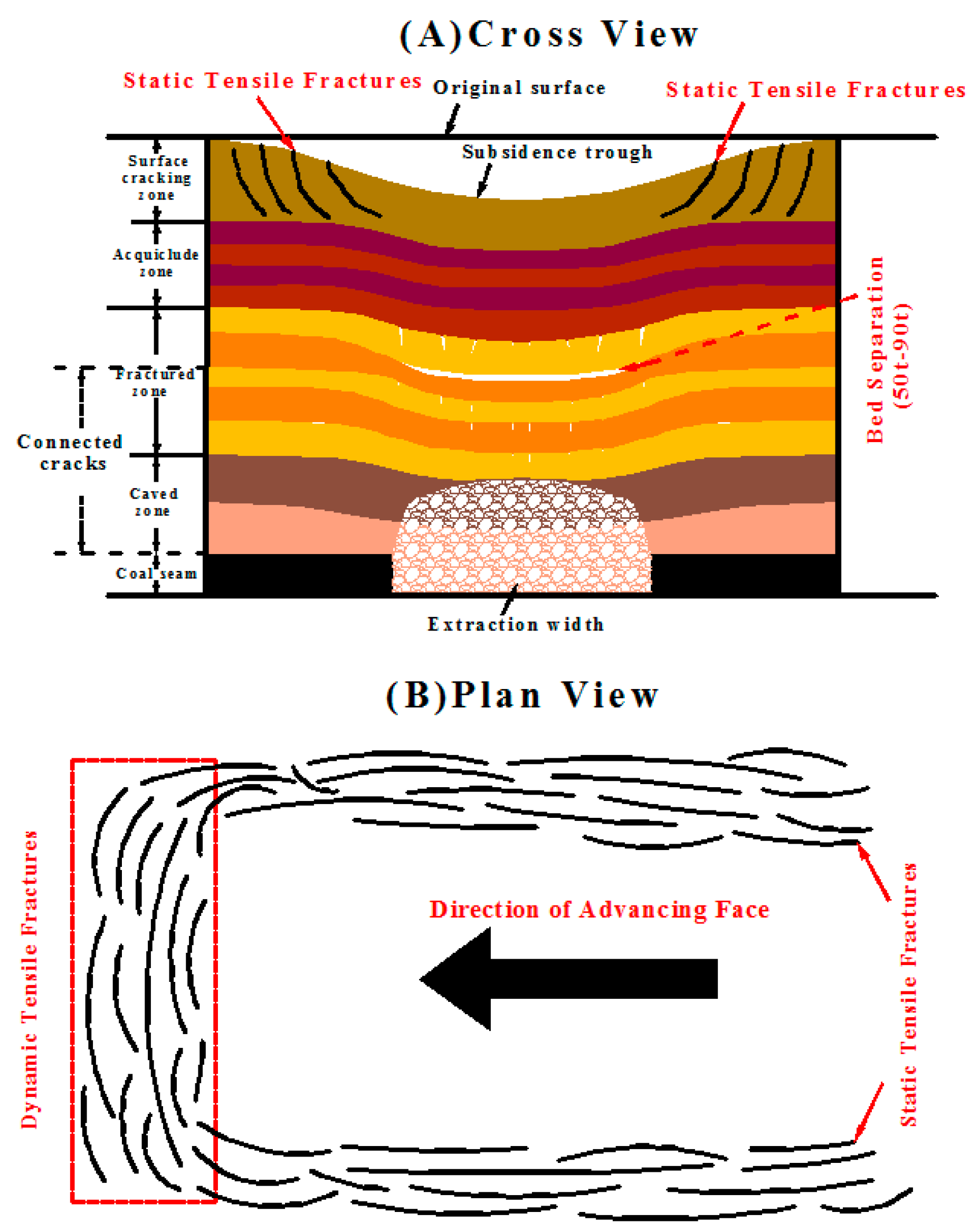
When a site is undermined, nature will ultimately search for the most stable state, which is a collapse of the void and a redistribution of the stress patterns causing the initiation and growth of overburden fractures [1,45,48,49]. Undoubtedly, the lowest part of the strata above the mine level experiences the most severe fracturing with fracture initiation in shear from the wings of the excavation, creating numerous upward propagating fractures [4,15], whereas the shallow strata suffer from a certain amount of tensional stresses, leading to shear deformation and surface tensional cracks [5]. As the shields (hydraulic supports) move, the mine roof behind them continues to cantilever and caves into the mine void, which experiences the process of elastic deformation, plastic deformation, and failure [16,20], producing two types of tensile fractures at the surface over the panel: static tensile fracture above the side of a panel and dynamic tensile fractures that follow behind the advancing face [16,17]. The dynamic tensile fractures close as a result of compressional stress after the advance of the face, and static tensile fractures remain open for several months after mining [17], which experience a process of appearance, enlargement, and closure due to initial dilation and later compression of the joints, fractures, and bedding separations. After first weighting, fractures develop in front of the face. In addition, shear deformation mainly occurs in weaker strata or along weak–strong rock layer interfaces over the edge of the panel, yet in the center failure, this occurs mainly as bedding separations, especially at lithologic interfaces [4]. Overall, the overburden strata generally experience the stages of caving, bedding separation, bedding plane sliding, shear or tensional deformation, failure, crack propagation, and recompaction. It is also obvious that the fracturing of overlying strata in the shallow part is much less than in the deeper part [15,50,51].
Irrespective of the influence of significant structures, however, fracture development of overburden strata during the mining process is still dependent on many parameters such as the strength and thickness of the roof material, number of rock layers, face width, geometry of the jointing pattern, overburden thickness, topography, mining direction, and single- or multi-slice extraction of coal. In situations where multi-slice extraction of coal is conducted, it leads to a greater degree of fracturing upwards than single slice extraction in the overburden strata, which also results from the increasing number of rock layers [15,27]. If the strength and thickness of the main or immediate roof are stiff and thick enough to prevent fracturing, no obvious mining-induced fractures would be found ahead of the face. Because the topography is not flat, the fracture profiles along the centerline of the panel are not expected to be symmetric; even the mining direction beneath a ragged topography, face width, and the geometry of the mined void can affect the development of the surface deformations and the extent of the fracturing [9,17,35,36,52]. Accordingly, a study on mining-induced fractures that involve many affecting factors is a complex undertaking, and its fundamental theory still requires much work in the future.
2.2. Effects on Subsidence of Longwall Mining
Bedding separations and fracture openings, causing the ground to subside rapidly with continuous exploitation, are well-demonstrated features of subsidence [5,6]. Subsidence progresses upwards through the overburden to the ground surface, where a subsidence trough develops and outlines the mined-out panel [4,23] (seen in Figure 2). The front part of the subsidence zone, and thus the earliest phase of subsidence, is dilated, whereas the rear part, and thus the latter phase, is compressional. The outer sides of the trough undergo only the tensional phase, but the inner area is swept by initial tensional and subsequent compressional phases [4]. The first ground subsidence generally occurs in advance of the mining face and closely follows the face, whereas the majority of the subsidence located in the geometrical center of the excavation occurs in the few days after passing the mining face and continues for several weeks [5,12,14].
The main causes of subsidence are geological discontinuities, which are either created or accelerated by humans [31,34,41]. The subsidence factors mainly include the method and parameters of mining, width of the panel, thickness of the overburden, angle of the draw, dip of the coal seam, depth and thickness of the coal seam, geological and stratigraphic conditions, and so on [14,18]. Engineering practices show that the fully mechanized slice mining and multi-seam mining generally give rise to greater subsidence as a result of the larger extraction quantity and repeated mining disturbance. A subsidence event may also be enhanced by a larger panel width and mined seam thickness, smaller thickness of the overburden, and low angle of draw. The maximum subsidence is found to increase with increasing depth of mined coal and thus decreases gradually with larger depth, whereas the dip angle only gently changes the shape of subsidence and produces less influence [1,14,24]. According to Society of Mining Engineers [33], the unconsolidated materials (e.g., sand, silt, clay) at or near the surface are extremely vulnerable to caving, propagating subsidence effects. However, the subsidence period relies on the lateral distance from the mining face and its advancing rate, and at a higher rate of advancing, subsidence always occurs at a higher rate [16].
2.3. Interactions between Subsidence and Water Bodies
The changing fracture and subsidence are the primary driving mechanisms for much of the head drop, depressed water level, and altered hydraulic gradients [6,12]. In confined bedrock aquifers, transient and steep head drops occur as a result of low storativity recharging that is less than discharging into the new void space, which creates a temporary local potentiometric depression with directly interconnected flow paths to the subsided strata. If the transmissivity of the affected unit is not poor, a resultant drawdown effect significantly and gradually transmits through the aquifer outwards from the advancing subsidence zone as a result of groundwater beyond this zone draining toward the potentiometric low, and thus typically expands a few hundred meters [4,12]. Additionally, the most significant changes of hydraulic properties occur during the period of maximum subsidence. Increases of one or two orders of magnitude in permeability and a moderate increase in storativity from before and after subsidence are often reported, along with typical increases of an order of magnitude in the inner subsidence and two in the marginal tensional zone [5,6,46].
3. Trapezoid Broken Model to Calculate Mining-Induced Fracture Parameters
Although the current results of the studies of the mining effects on the development characteristics of mining-induced fractures, subsidence, and their associated water loss have been known for decades, the mechanism for the calculation of fracture parameters due to caving strata remain elusive. In this study, three study models are proposed and outlined henceforth, which give us the corresponding solutions to the above problems.
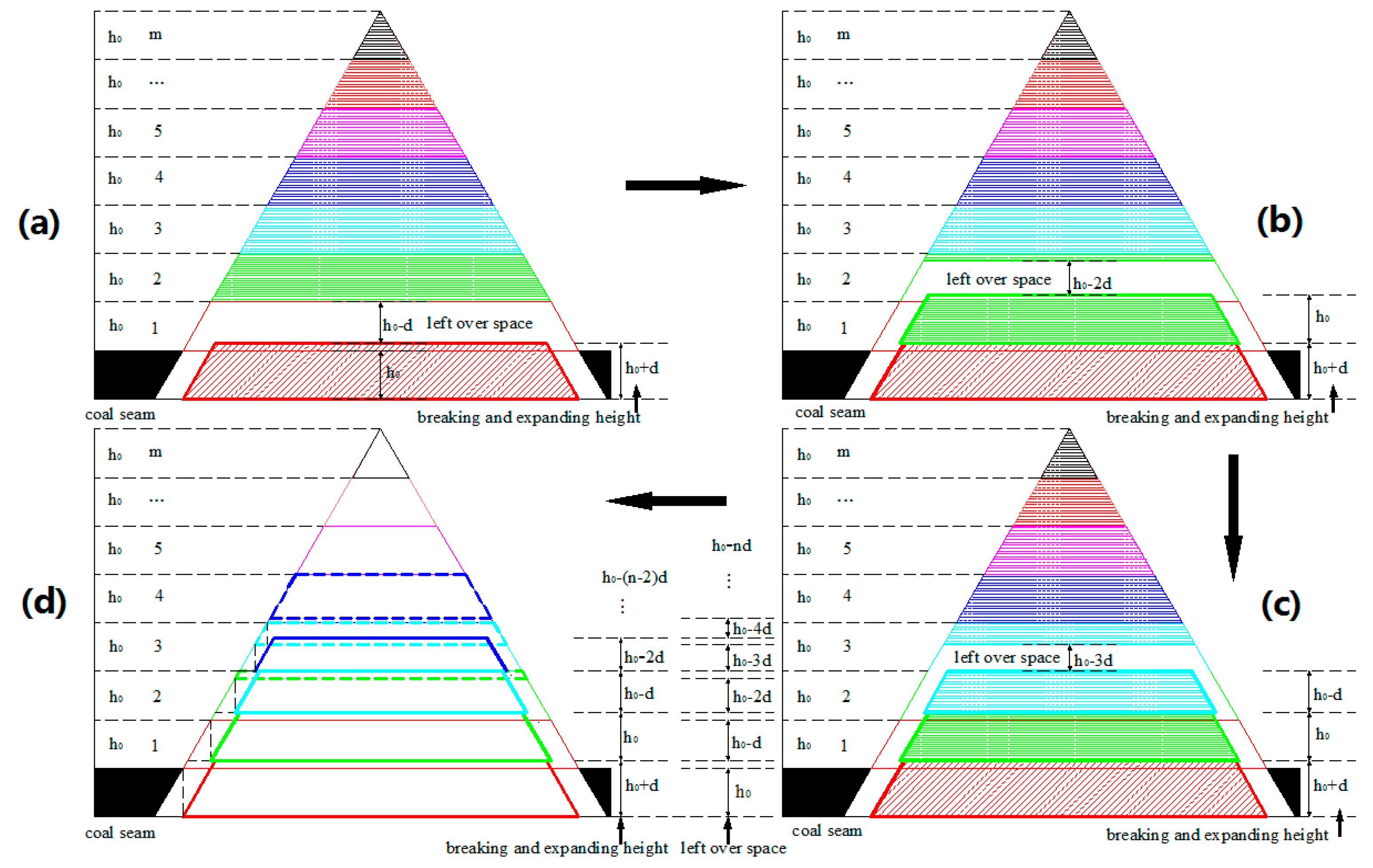
There are many critical factors influencing the overburden fracturing and caving mechanisms during the coal process such as discontinuities, strata characteristics, mining height, etc. This paper is focused on a type of the broken pattern of massive strata controlled by the volume expansion coefficient and its consequent fracture parameters calculation, and for the convenience of research we perform this study under the condition of less interfering factors, and other critical factors will be added in future research. In this model, it is assumed that the destressed zone including the caved and fracturing zone caves in a trapezoidal pattern ultimately expands up to a “trapezium” or a “triangle”; and every layer of roof strata above the excavated area has an equal thickness to that of the coal seam (h0). Furthermore, these strata are numbered as m from bottom up, and m = 1 represents the layer of the mined coal seam. Given that the coal seam is mined, the roof strata would break down in sequence, causing the remaining void left on both sides of the collapsed and expanded strata to form a series of fracture passages with different equal widths of the parallelogram at each caving layer, but unequal width in different caving layers. Since the definition of the caving number cannot affect the following proposed formula and results, and for the purpose of simplifying the formula, we define the number of first caving and expansion after the coal is mined as (0)th caving seen in Figure 3a, and the caving number of these strata is numbered as (1)th, (2)th,...,(n − 1)th from the bottom up, seen in Figure 3b–d. Theoretically, without volume dilation, it is possible for the volume of the broken layer to fill the mined space equally.
3.1. Model Study I
In this model, it is assumed that the broken layer extends only upward along the two edges of the trapezoid longitudinally without lateral expansion, and it has a volume expansion coefficient expressed by “d”. Thus, when the coal seam is extracted, the height of the (0)th broken material amounts to , and the remaining space above it equals , displayed in Figure 3a. From Figure 3b–d we can assume that the (n − 1)th leftover height is in terms of the development tendency, and the corresponding breaking and expanding height is then . After summation, we can obtain the total thickness of the breaking and expanding roof strata which reflects the height of the destressed zone, , seen in Equation (1) as follows. Actually, it is the sum of all broken and expanding heights, plus the last left-over height, minus the thickness of the coal seam [22].
When the (n)th leftover height, , is determined by 0, the limiting value of n can be indicated by
Substituting n of Equation (1) with Equation (2), we can obtain the limiting equation by solving for the height of the destressed zone:
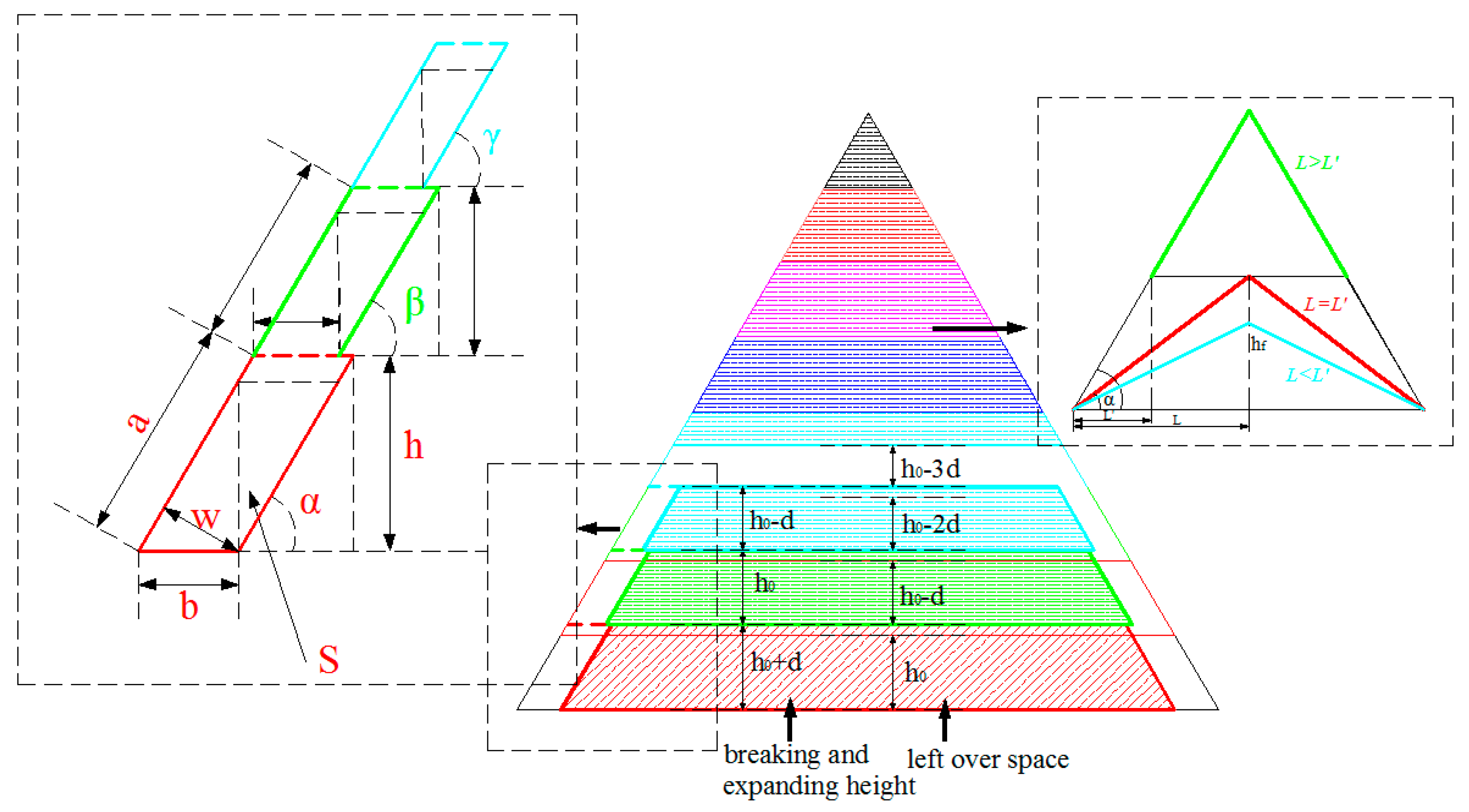
Meanwhile, a series of fracture passages with unequal parallelogram widths would emerge at both ends of the trapezoid. Using this model, some parameters of mining-induced fractures can be quantitatively described. As seen in Figure 4, each parallelogram passageway has its own lengths of the long side (a) and short side (b), width (W), and area (S). When the first roof stratum caves in and extends to form the first fracture passageway of the parallelogram, we can acquire all parameters of this parallelogram according to the presupposed fracture angle (α) and the given breaking and expanding height (h). In this part, the parallelogram of each layer has the same fracture angle, that is, . As the trapezoidal broken model steps upwards, the corresponding passageway parameters can be calculated.
The ultimate caving configuration and how to connect the face width with the fracture angle and the height of the distressed zone are discussed in this model. There are three situations that can be discussed as follows. In the first case, only when the altitude of the trapezoidal broken model is equivalent to the height of the triangle, or , can this model eventually evolve into the shape of a triangle; that is,
Substituting of Equation (4) with Equation (3), we obtain the value of α:
where α is the fracture angle, and is half of the face width. It is clear from this equation that the larger the degree of the fracture angle, the smaller the values of the volume expansion coefficient and face width with a relatively larger mining height. By this equation, we can provide some basic information on the conditions under which a trapezoidal broken model evolves into the shape of a triangle, and the degrees to which the fracture angle emerges under certain mining parameters.
In the second instance, if as shown in Figure 4, then a trapezoidal broken model would form in the shape of a trapezium rather than a triangle; that is,
Solving for α, we can obtain
From Equation (7), we see that when the fracture angle is larger than the right-hand side of this equation, the trapezoidal broken model would extend upwards as a trapezium.
For the last case, if as shown in Figure 4, the roof broken strata cannot develop in accordance with the patterns of the trapezoidal broken model and finish in a triangle ahead of time. The height of the destressed zone is constrained by both sides of the triangle and cannot freely extend upwards. Thus, we can obtain
In the first two cases, we can obtain the area of the fracture passages (S) at one side:
3.2. Model Study II
Under the premise of the defined model I, it is presumed that the broken layer can also extend in the lateral direction with a lateral expansion coefficient expressed by “”, in addition to upward expansion. Meanwhile, by disregarding the conflicts of the limiting value between the last vertical and lateral expansion, we can obtain the following parameter equations in Table 1 by combining the results of model I.
From the foregoing analysis, we can also acquire the area of the fracture passages (S) at one side:
3.3. Model Study III
In order to be consistent with the assumptions made in model I, model III assumes that the broken layer extends upward only along the two edges of the trapezoid longitudinally without lateral expansion, and that it has a volume expansion coefficient expressed by “d” on the (0)th broken stratum, which has an upward trend with a decreasing volume expansion coefficient, (seen in Figure 5). That is, the volume expansion coefficient of the (0)th caving stratum is , and that of the (n)th caving stratum is . Thus, when the coal seam is extracted, the height of the first broken material amounts to , and the remaining space above it equals . The (n)th breaking and expanding height is , and the corresponding leftover height is . After summation, we can obtain the total thickness of the breaking and fracturing roof strata which reflects the height of the destressed zone, , seen in Equation (11) as follows. It is the sum of all broken and dilated heights, plus the last leftover height, minus the thickness of the coal seam.
When the roof strata no longer caves and/or expands, the volume expansion coefficient is reduced to 0, and the limiting value of n can be indicated by
Substituting n of Equation (11) with Equation (12), we can obtain the limiting equation by solving for the height of the destressed zone:
Similar to model I, we can obtain the calculation formula of a series of parameters of S, α, and so on. In this part, we display only the formula for S as follows:
4. Discussion
In this study, in conjunction with engineering practices, subsidence and fracture changes during the mining process have been presented and analyzed. One type of conceptual model was assumed to present the effects of mining on overburden strata movement.
A type of trapezoidal broken model in the profile perpendicular to the face advance was proposed to calculate various parameters of fractures induced by coal mining, which would cause the remaining void left on both sides of the collapsed and expanded strata to form a fracture passage with unequal parallelogram widths. Three models that consider the lateral and longitudinal volume expansion coefficients were assumed to reveal different calculation methods of the fracture passageway parameters, especially the passageway area. For example, taking model I to connect the face width with the fracture angle and the height of the destressed zone, three cases were covered, and their evolution configurations were studied. Based on probing their relationships, the trapezoid broken model can be used to better study the caving patterns and to count the fracture space induced by caving in longwall mining, which would inevitably cause water bodies in overlying strata to move towards these new space. Furthermore, the ultimate caving configuration model and its three cases were discussed. In addition, in the case of the shape of a triangle, by adopting the values of , , , and α that conform to the actual production in the formula of the fracture angles, we can acquire a series of ranges of the fracture angles and their corresponding parameter values. Thus, we chose two representative ranges of the fracture angles, 40°–50° and 50°–60°, which are largely associated with the measured, experimental, and theoretical results of many scholars [28,31,40,51] from the literature on fracture angles due to coal mining. From these two ranges, we find that the larger the degree of the fracture angle, the smaller the value of the volume expansion coefficient and face width with a relatively larger mining height. These results enable us to know the conditions under which the trapezoidal broken model evolves into the shape of a triangle and the degree fracture angle that emerges under different mining parameters. Additionally, the determination of fracture space using these parameters may provide a new method for the calculation of the new space amount in overlying strata due to coal mining. We confirm that the groundwater flow appears to be controlled by this new fracture space. By using this idea, we could predict the water loss amount of aquifers in advance and do a good job of guarding against potential water-inrush accidents, which can also provide a reference for the numerical simulation and mathematical analysis in caving mechanisms and its new fracture space, water loss problems related to mining engineering, etc.
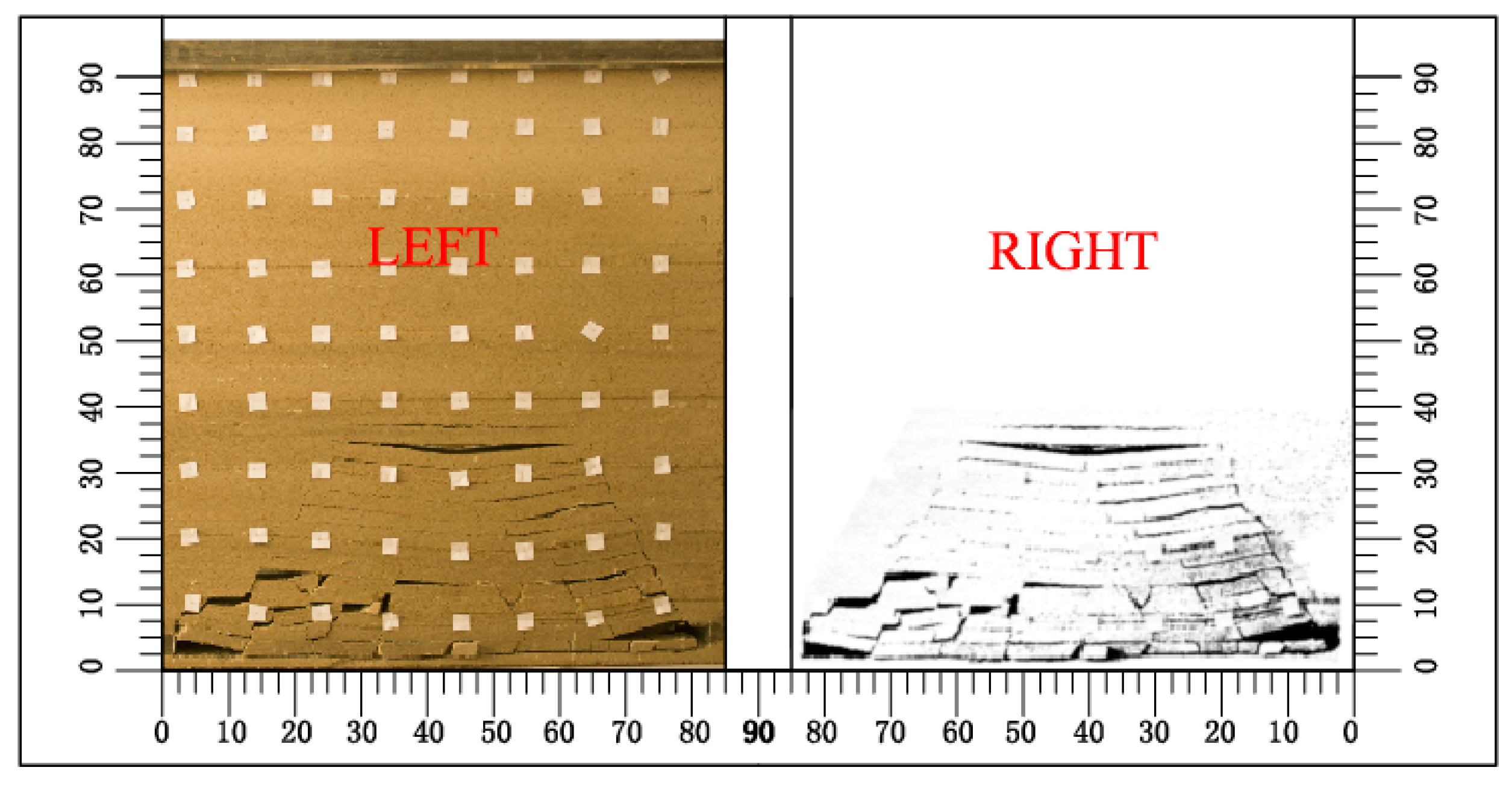
To validate the conceptual model in the paper, we did a similar material simulation experiment; the length × width × height of this model is 90 cm × 90 cm × 90 cm. When the coal seam was excavated, the face advancing distance proceeded up to 85 cm in 5 cm intervals with the boundary coal-pillar of 2.5 cm respectively left at both ends. Every layer of the roof strata above the excavated area has an equal thickness to the coal seam and the same lithologic features, which is similar to the assumptions of the conceptual model. It can be seen in Figure 6 that the left and right pictures are of the practical caving of the similar model and the digital image analysis detecting the fracture after excavation, respectively. The similar model indicated that the overall fracture configuration of the overburden strata had a trapezoid-like shape and a general decreasing trend of the fracture space from the bottom up at both sides, which basically coincides with the proposed conceptual model. However, the similar material experiment is still different from practical mining, and further research is needed.
Among the above conceptual models, the selection of the expansion coefficient is considered to be too uneven. For example, the lateral expansion coefficient from the bottom to the top is the same. In effect, as strata cave in, the space of lateral expansion is limited and should grow increasingly smaller. Future research should include the parameter of fracture space under the conditions of various variation tendencies of the lateral or vertical expansion coefficient. Moreover, studies on the caving pattern of longwall mining involve many factors such as strata characteristics, mining height, and so on, and these factors should be added in the future.
5. Conclusions
In the course of coal mining, the broken pattern of the overburden strata induced by mining has a non-ignorable effect on overlying strata movement, failure, and safety in mining production. In this study, one type of conceptual model was proposed, which includes the broken patterns of the overburden strata and the fracture space induced by it. The authors proposed three types of trapezoidal broken models considering the top-down varying pattern of the lateral and longitudinal volume expansion coefficients. In these models, the face width was connected with the fracture angle and the height of the destressed zone to explore the eventual evolution configuration of the broken model: a triangle or a trapezium. These models may help us understand the caving mechanism of overburden strata and the formation of fracture space, which would provide guidelines for coal mining under water bodies and could predict the occurrence of water-inrush accidents. This research is of great significance to the safe production of coal mines and to satisfy energy needs for human beings. However, attention must be paid to more complex caving models that consider more influencing factors such as structure development, strata characteristics, etc. The conceptual model should be further validated against other approaches in future research.
Acknowledgments
Our deepest gratitude goes to the editors and reviewers for their careful work and thoughtful suggestions that have helped improve this paper substantially. The authors also gratefully acknowledge the financial support of the National Science and Technology Supporting Program (Grant 2012BAB13B01), the National Key Scientific Instrument and Equipment Development Program (Grant 2012YQ030126), the Coal United Project of National Natural Science Foundation (Grant U1261203), the China Geological Survey Project (Grant 1212011220798), and the National Science and Technology Major Project (Grant 2011ZX05035-004-001HZ).
Author Contributions
Suping Peng and Dongjing Xu proposed this model; Shiyao Xiang and Yunlan He drew the pictures and analyzed the data; Dongjing Xu wrote the paper.
Conflicts of Interest
The authors declare no conflict of interest.
References
- Bahuguna, P.P.; Srivastava, A.M.C.; Saxena, N.C. A critical review of mine subsidence prediction methods. J. Min. Sci. Technol. 1991, 13, 369–382. [Google Scholar] [CrossRef]
- Bárdossy, A.; Hörning, S. Gaussian and non-Gaussian inverse modeling of groundwater flow using copulas and random mixing. Water Resour. Res. 2016, 52. [Google Scholar] [CrossRef]
- Bayram, A.; Önsoy, H. Sand and gravel mining impact on the surface water quality: A case study from the city of Tirebolu (Giresun Province, NETurkey). Environ. Earth Sci. 2015, 73, 1997–2011. [Google Scholar] [CrossRef]
- Booth, C.J.; Spande, E.D.; Pattee, C.T.; Miller, J.D.; Bertsch, L.P. Positive and negative impacts of longwall mine subsidence on a sandstone aquifer. Environ. Geol. 1998, 34, 223–233. [Google Scholar] [CrossRef]
- Booth, C.J. Groundwater as an environmental constraint of longwall coal mining. Environ. Geol. 2006, 49, 796–803. [Google Scholar] [CrossRef]
- Booth, C.J. Confined-unconfined changes above longwall coal mining due to increases in fracture porosity. Environ. Eng. Geosci. 2007, 13, 355–367. [Google Scholar] [CrossRef]
- Booth, C.J. Strata-movement concepts and the hydrogeological impact of underground coal mining. Ground Water 1986, 24, 507–515. [Google Scholar] [CrossRef]
- Chang, J.; Leung, D.Y.C.; Wu, C.Z.; Yuan, Z.H. A review on the energy production, consumption, and prospect of renewable energy in China. Renew. Sustain. Energy Rev. 2003, 7, 453–468. [Google Scholar] [CrossRef]
- Franks, C.A.M.; Geddes, J.D. Subsidence on steep slopes due to longwall mining. Geotech. Geol. Eng. 1986, 4, 291–301. [Google Scholar] [CrossRef]
- Gordalla, B.C.; Ewers, U.; Frimmel, F.H. Hydraulic fracturing: A toxicological threat for groundwater and drinking-water? Environ. Earth Sci. 2013, 70, 3875–3893. [Google Scholar] [CrossRef]
- Gregory, K.B.; Vidic, R.D.; Dzombak, D.A. Water management challenges associated with the production of shale gas by hydraulic fracturing. Elements 2011, 7, 181–186. [Google Scholar] [CrossRef]
- Hill, J.G.; Price, D.R. The impact of deep mining on an overlying aquifer in western Pennsylvania. Ground Water Monit. Remediat. 1983, 3, 138–143. [Google Scholar] [CrossRef]
- Howladar, M.F. Coal mining impacts on water environs around the Barapukuria coal mining area, Dinajpur, Bangladesh. Environ. Earth Sci. 2012, 70, 215–226. [Google Scholar] [CrossRef]
- Howladar, M.F.; Hasan, K. A study on the development of subsidence due to the extraction of 1203 slice with its associated factors around Barapukuria underground coal mining industrial area, Dinajpur, Bangladesh. Environ. Earth Sci. 2014, 72, 3699–3713. [Google Scholar] [CrossRef]
- Islam, M.R.; Hayashi, D.; Kamruzzaman, A.B.M. Finite element modeling of stress distributions and problems for multi-slice longwall mining in Bangladesh, with special reference to the Barapukuria coal mine. Int. J. Coal Geol. 2009, 78, 91–109. [Google Scholar] [CrossRef]
- Karacan, C.Ö.; Goodman, G. Hydraulic conductivity changes and influencing factors in longwall overburden determined by slug tests in gob gas ventholes. Int. J. Rock Mech. Min. 2009, 46, 1162–1174. [Google Scholar] [CrossRef]
- Karaman, A.; Seyhan, T.; Işık, M.F. Detecting the footprint of a longwall mine panel claimed to infringe on a permit boundary at the Soma–Darkale coalfield (Manisa, Turkey) using surface fractures and microgravity measurements. Environ. Earth Sci. 2013, 70, 1895–1902. [Google Scholar] [CrossRef]
- Lee, D.K.; Mojtabai, N.; Lee, H.B.; Song, W.K. Assessment of the influencing factors on subsidence at abandoned coal mines in South Korea. Environ. Earth Sci. 2013, 68, 647–654. [Google Scholar] [CrossRef]
- Li, G.Y.; Zhou, W.F. Impact of karst water on coal mining in North China. Environ. Geol. 2006, 49, 449–457. [Google Scholar] [CrossRef]
- Liu, J.; Elsworth, D. Three-dimensional effects of hydraulic conductivity enhancement and desaturation around mined panels. Int. J. Rock Mech. Min. 1997, 34, 1139–1152. [Google Scholar] [CrossRef]
- Ma, L.Q.; Zhang, D.S.; Li, X.; Fan, G.W.; Zhao, Y.F. Technology of groundwater reservoir construction in goafs of shallow coalfields. Int. J. Min. Sci. Technol. 2009, 19, 730–735. [Google Scholar] [CrossRef]
- Majdi, A.; Hassani, F.P.; Nasiri, M.Y. Prediction of the height of destressed zone above the mined panel roof in longwall coal mining. Int. J. Coal Geol. 2012, 98, 62–72. [Google Scholar] [CrossRef]
- Mehnert, B.B.; Van-Roosendaal, D.J.; Bauer, R.A.; DeMaris, P.J.; Kawamura, N. Final Report of Subsidence Investigations at the Rend Lake Site, Jefferson County, Illinois; Coop Agreement CO267001; Illinois State Geological Survey, US Department of the Interior: Quincy, IL, USA, 1994. [Google Scholar]
- Mills, C.E. Ground movement and subsidence at the United Verde mine. Trans. AIME 1934, 109, 153–172. [Google Scholar]
- Molson, J.; Aubertin, M.; Bussière, B. Reactive transport modelling of acid mine drainage within discretely fractured porous media: Plume evolution from a surface source zone. Environ. Model. Softw. 2012, 38, 259–270. [Google Scholar] [CrossRef]
- Osborn, S.G.; Vengosh, A.; Warner, N.R.; Jackson, R.B. Methane contamination of drinking water accompanying gas-well drilling and hydraulic fracturing. Proc. Natl. Acad. Sci. USA 2011, 108, 8172–8176. [Google Scholar] [CrossRef] [PubMed]
- Palchik, V. Formation of fractured zones in overburden due to longwall mining. Environ. Geol. 2003, 44, 28–38. [Google Scholar]
- Palchik, V. Application of Mohr–Coulomb failure theory to very porous sandy shales. Int. J. Rock Mech. Min. Sci. 2006, 43, 1153–1162. [Google Scholar] [CrossRef]
- Panthulu, T.V.; Krishnaiah, C.; Shirke, J.M. Detection of seepage paths in earth dams using self-potential and electrical resistivity methods. Eng. Geol. 2001, 59, 281–295. [Google Scholar] [CrossRef]
- Peksezer-Sayit, A.; Cankara-Kadioglu, C.; Yazicigil, H. Assessment of dewatering requirements and their anticipated effects on groundwater resources: A case study from the Caldag Nickel Mine, Western Turkey. Mine Water. Environ. 2015, 34, 122–135. [Google Scholar] [CrossRef]
- Saloustros, S.; Pelà, L.; Cervera, M. A crack-tracking technique for localized cohesive-frictional damage. Eng. Fract. Mech. 2015, 150, 96–114. [Google Scholar] [CrossRef]
- Singh, B.K.; Dhar, B.B. Sinkhole subsidence due to mining. Geotech. Geol. Eng. 1997, 15, 327–341. [Google Scholar] [CrossRef]
- Society of Mining Engineers. Mine Subsidence; Singh, M.M., Ed.; Society of Mining Engineers, American Institute of Mining: New York, NY, USA, 1986; pp. 73–143. [Google Scholar]
- Soliman, M.M.; LaMoreaux, P.E.; Memon, B.A.; LaMoreaux, J.W.; Assaad, F.A. Environmental Hydrogeology, 2nd ed.; IWA Publishers: London, UK, 2008; pp. 81–101. [Google Scholar]
- Tammetta, B.P. Estimation of the height of complete groundwater drainage above mined longwall panels. Ground Water 2014, 52, 923–935. [Google Scholar] [CrossRef] [PubMed]
- Tammetta, B.P. Estimation of the change in hydraulic conductivity above mined longwall panels. Ground Water 2014, 53, 122–129. [Google Scholar] [CrossRef] [PubMed]
- Trevits, M.A.; Matetic, R.J. A study of the relationship between saturated zone response and longwall mining-induced ground strain. In Proceedings of the NWWA Fifth National Outdoor Action Conference on Aquifer Restoration, Ground Water Monitoring, and Geophysical Methods, Las Vegas, NV, USA, 13–16 May 1991; pp. 1101–1109. [Google Scholar]
- White, E.K.; Peterson, T.J.; Costelloe, J.; Western, A.W.; Carrara, E. Can we manage groundwater? A method to determine the quantitative testability of groundwater management plans. Water. Resour. Res. 2016, 52. [Google Scholar] [CrossRef]
- Whittaker, B.N.; Reddish, D.J. Subsidence: Occurrence, Prediction and Control: Developments in Geotechnical Engineering; Elsevier: New York, NY, USA, 1989; Volume 56, p. 528. [Google Scholar]
- Wu, J.Y.; Cervera, M. On the equivalence between traction- and stress-based approaches for the modeling of localized failure in solids. J. Mech. Phys. Solids 2015, 82, 137–163. [Google Scholar] [CrossRef]
- Wu, Q.Y.; Pang, J.W.; Qi, S.Z.; Li, Y.P.; Han, C.C.; Liu, T.X.; Huang, L.M. Impacts of coal mining subsidence on the surface landscape in Longkou city, Shandong province of China. Environ. Geol. 2009, 59, 783–791. [Google Scholar]
- Xu, D.J.; SPeng, P.; Xiang, S.Y.; Liang, M.X.; Liu, W.M. The effects of caving of a coal mine’s immediate roof on floor strata failure and water inrush, Mine. Water. Environ. 2016, 35, 337–349. [Google Scholar] [CrossRef]
- Yang, Y.K.; Kang, T.H.; Hao, X.L.; Zheng, T.B.; Wang, A. Research on in-situ purification technique of mine water in Shendong mining area. Energy Educ. Sci. Technol. 2012, 29, 209–216. [Google Scholar]
- Yang, T.H.; Liu, J.; Zhu, W.C.; Elsworth, D.; Tham, L.G.; Tang, C.A. A coupled flow-stress-damage model for groundwater outbursts from an underlying aquifer into mining excavations. Int. J. Rock Mech. Min. 2007, 44, 87–97. [Google Scholar] [CrossRef]
- Yu, S.W.; Wei, Y.M. Prediction of China’s coal production-environmental pollution based on a hybrid genetic algorithm-system dynamics model. Energy Policy 2012, 42, 521–529. [Google Scholar] [CrossRef]
- Vukelić, Ž.; Dervarič, E.; Šporin, J.; Vižintin, G. The development of dewatering predictions of the velenje coalmine. Energies 2016, 9, 702. [Google Scholar] [CrossRef]
- Zhang, W.; Zhang, D.S.; Wu, L.X.; Wang, H.Z. On-site radon detection of mining-induced fractures from overlying strata to the surface: A case study of the Baoshan coal mine in China. Energies 2014, 7, 8483–8507. [Google Scholar] [CrossRef]
- Zhang, D.S.; Fan, G.W.; Liu, Y.D.; Ma, L.Q. Field trials of aquifer protection in longwall mining of shallow coal seams in China. Int. J. Rock Mech. Min. 2010, 47, 908–914. [Google Scholar] [CrossRef]
- Zhang, W.; Zhang, D.S.; Wu, L.X.; Wang, X.F. Numerical simulation on dynamic development features of mining induced fractures in overlying strata during shallow coal seam mining. Electron. J. Geotech. Eng. 2013, 18, 5531–5543. [Google Scholar]
- Zhang, D.S.; GFan, W.; Ma, L.Q.; Wang, X.F. Aquifer protection during longwall mining of shallow coal seams: A case study in the Shendong coalfield of China. Int. J. Coal Geol. 2011, 86, 190–196. [Google Scholar] [CrossRef]
- Zhang, Y.J.; Li, F.M. Monitoring analysis of fissure development evolution and height of overburden failure of high tension fully-mechanized caving mining, Chinese. J. Rock Mech. Eng. 2011, 30, 2994–3001. [Google Scholar]
- Zipper, C.; Balfour, W.; Roth, R.; Randolph, J. Domestic water supply impacts by underground coal mining in Virginia, USA. Environ. Geol. 1997, 29, 84–93. [Google Scholar] [CrossRef]
Figure 1.
Schematic cross-sectional view illustrating the longwall mining system along with the direction of the advancing face.
Figure 1.
Schematic cross-sectional view illustrating the longwall mining system along with the direction of the advancing face.

Figure 2.
Schematic view illustrating the mining-induced fracture system. (A) Cross review; (B) Plan review.
Figure 2.
Schematic view illustrating the mining-induced fracture system. (A) Cross review; (B) Plan review.

Figure 3.
Schematic cross-sectional drawing of the trapezoidal broken model showing the sequential caving of Model I: (a) after the (0)th layer failure of the roof stratum due to coal extraction, (b) after (1)th layer failure of the roof stratum, (c) after (2)th layer failure of the roof stratum, (d) after the (n−1)th layer failure of the roof stratum.

Figure 4.
Schematic diagram of the parallelogram fracture passages generated at both ends of the trapezoidal broken model.
Figure 4.
Schematic diagram of the parallelogram fracture passages generated at both ends of the trapezoidal broken model.

Figure 5.
Schematic cross-sectional drawing of the trapezoidal broken model showing the sequential caving of model III: (a) after the (0)th layer failure of the roof stratum due to coal extraction, (b) after (1)th layer failure of the roof stratum, (c) after (2)th layer failure of the roof stratum, (d) after the (n − 1)th layer failure of the roof stratum.
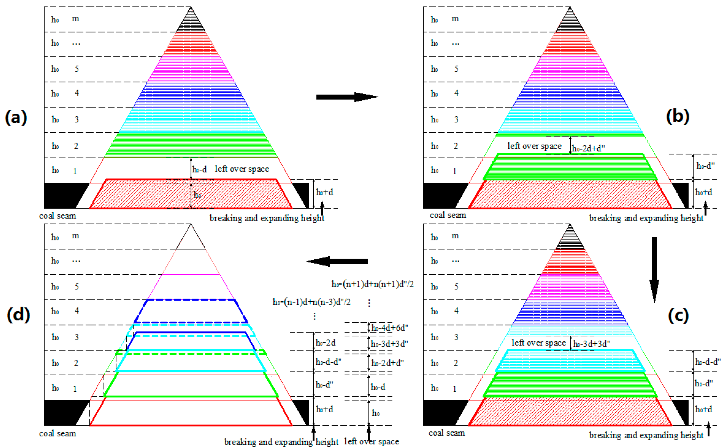
Figure 6.
Resulting picture of the similar material simulation experiment.

Table 1.
The parameters of the parallelogram fracture passages generated at both ends of the trapezoid in model II.
Table 1.
The parameters of the parallelogram fracture passages generated at both ends of the trapezoid in model II.
| Number of Caving Strata | Length of Long Side | Length of Short Side | Passageway Width | Passageway Area |
|---|---|---|---|---|
| 0 | ||||
| 1 | ||||
| 2 | ||||
| n − 2 | ||||
| n − 1 |
© 2017 by the authors. Licensee MDPI, Basel, Switzerland. This article is an open access article distributed under the terms and conditions of the Creative Commons Attribution (CC BY) license (http://creativecommons.org/licenses/by/4.0/).
Share and Cite
MDPI and ACS Style
Xu, D.; Peng, S.; Xiang, S.; He, Y. A Novel Caving Model of Overburden Strata Movement Induced by Coal Mining. Energies 2017, 10, 476. https://doi.org/10.3390/en10040476
AMA Style
Xu D, Peng S, Xiang S, He Y. A Novel Caving Model of Overburden Strata Movement Induced by Coal Mining. Energies. 2017; 10(4):476. https://doi.org/10.3390/en10040476
Chicago/Turabian StyleXu, Dongjing, Suping Peng, Shiyao Xiang, and Yunlan He. 2017. "A Novel Caving Model of Overburden Strata Movement Induced by Coal Mining" Energies 10, no. 4: 476. https://doi.org/10.3390/en10040476
Note that from the first issue of 2016, this journal uses article numbers instead of page numbers. See further details here.