
A Redundancy Mechanism Design for Hall-Based Electronic Current Transformers

Abstract
:1. Introduction
2. Hall-Based Electronic Current Transformer
3. Design of Redundancy Mechanism for the Proposed HCT
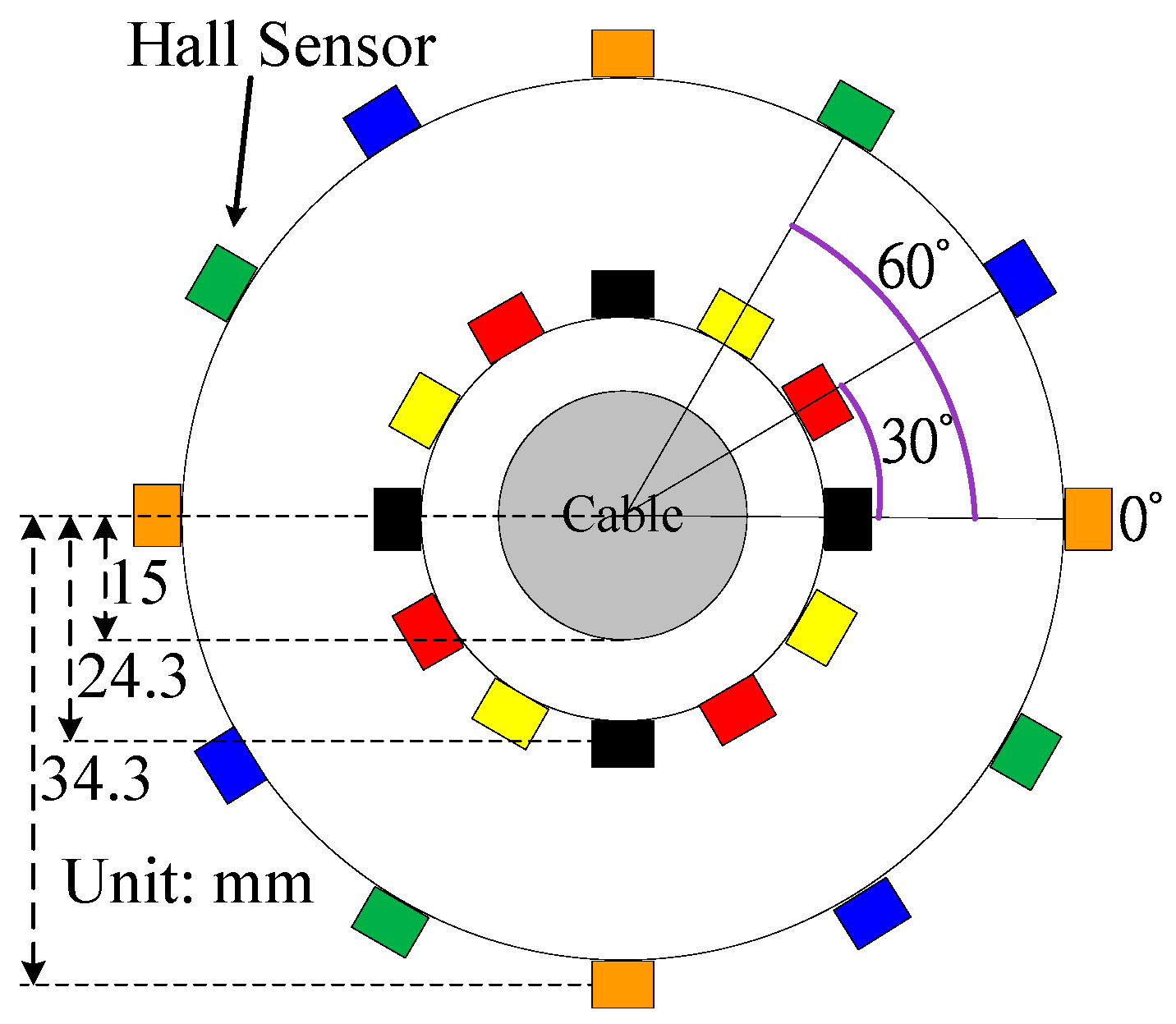
3.1. Sensing Structure and Sensor Module Amount
3.1.1. Double-Layer Sensing Structure
3.1.2. Single-Layer Sensing Structure
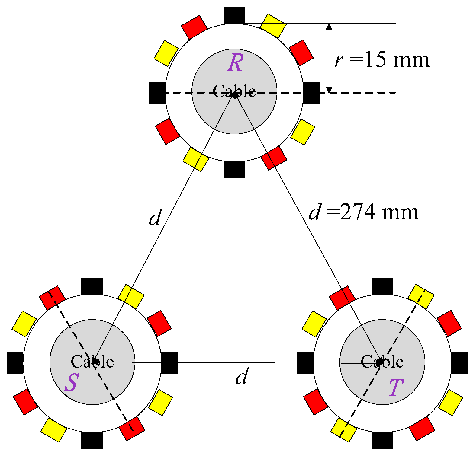
3.2. Single-Layer Sensing Structure in a Three-Phase System
3.2.1. Balanced Three-Phase System
3.2.2. Unbalanced Three-Phase System
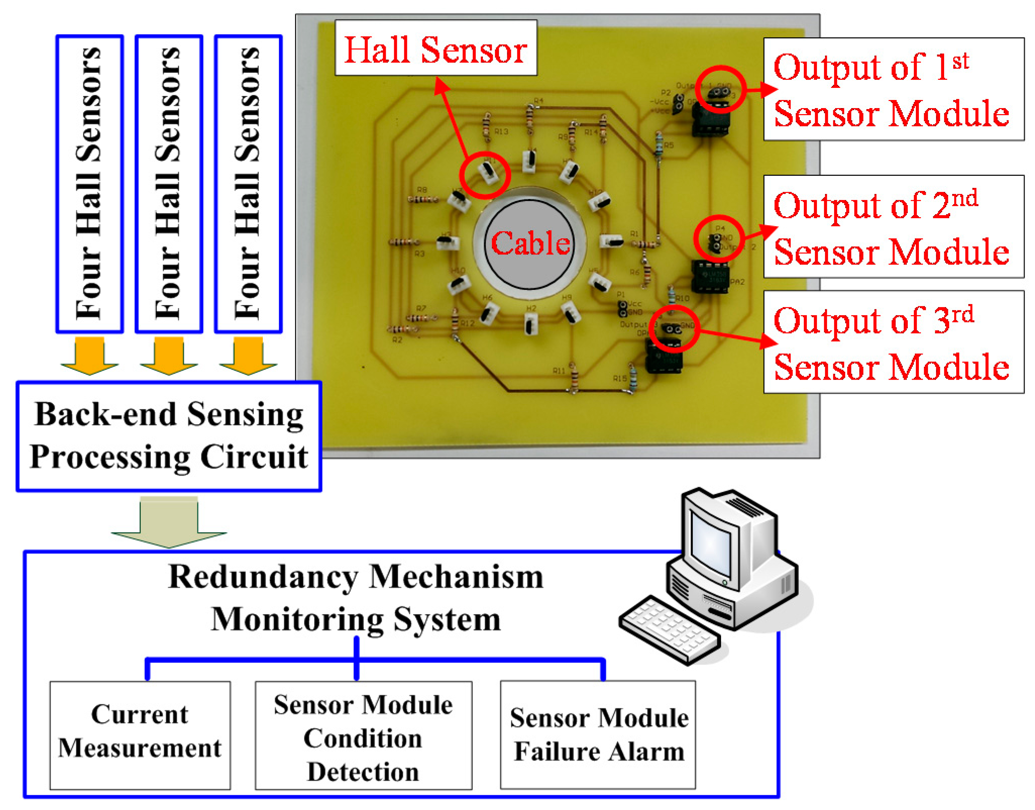
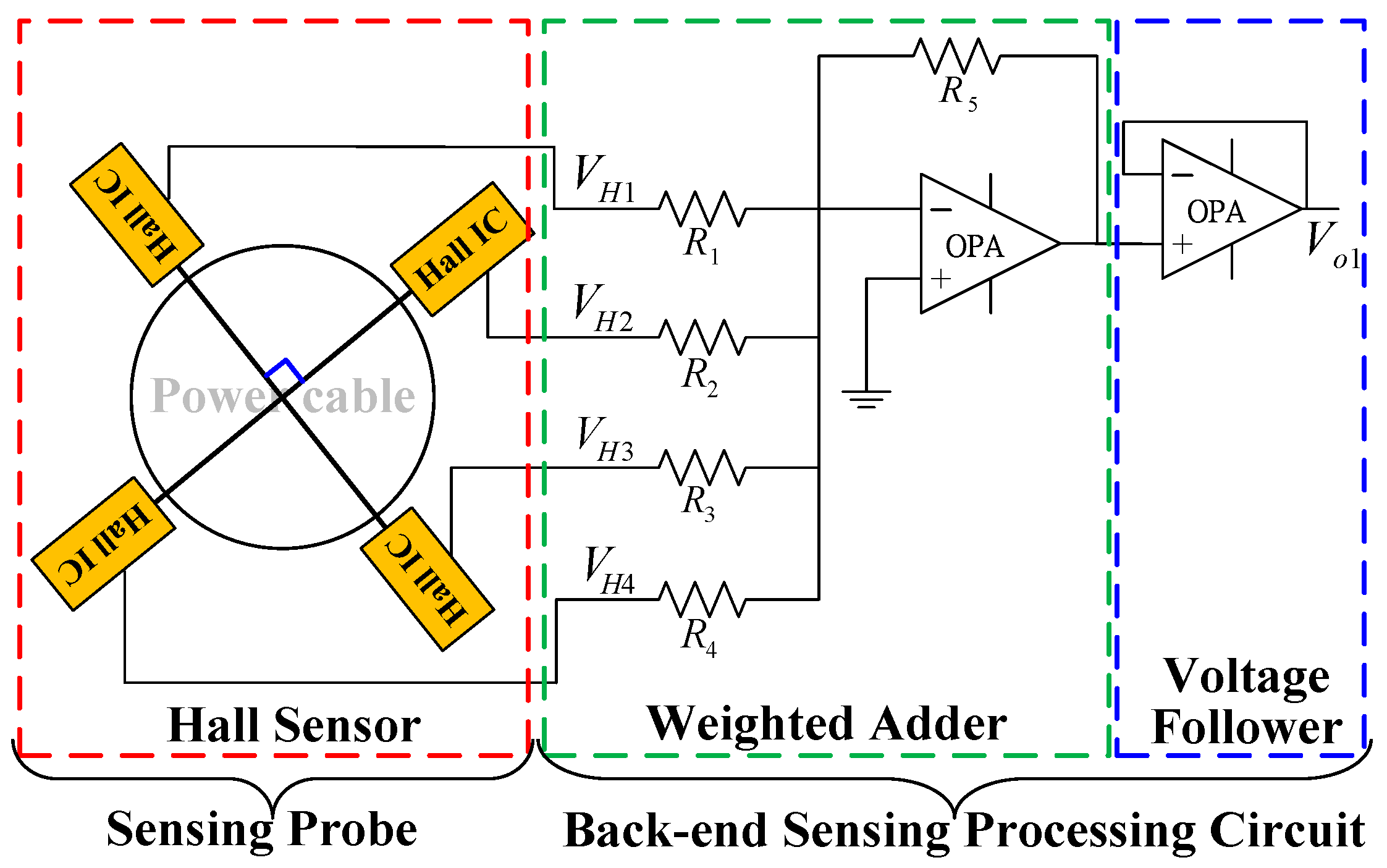
4. Implementation of the Redundancy Mechanism
4.1. Hardwire
- , , , : Outputs of four Hall sensors.
- , , , : 50 kΩ.
- : 10 kΩ.
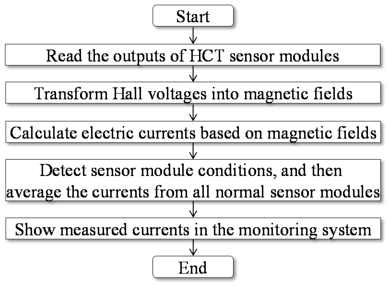
4.2. Software
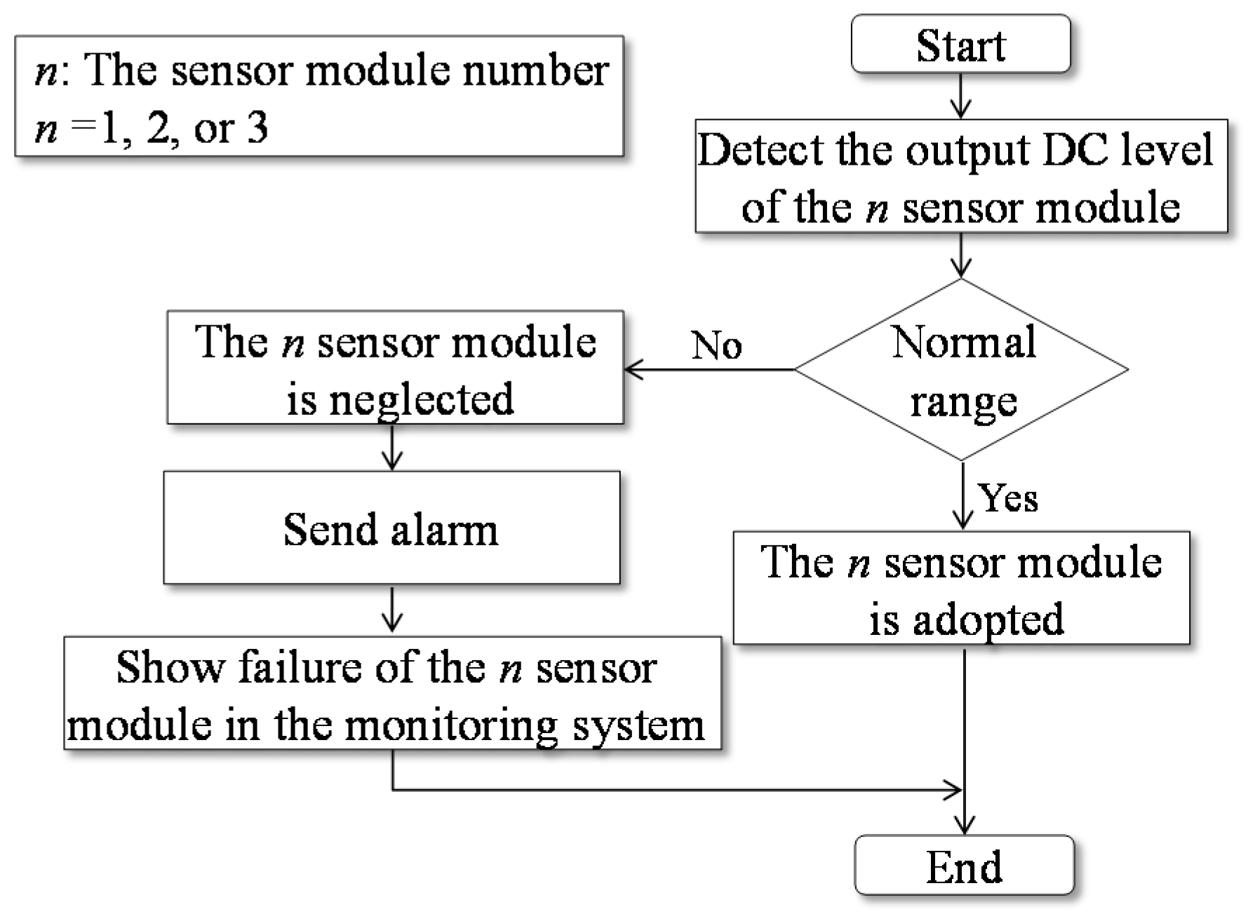
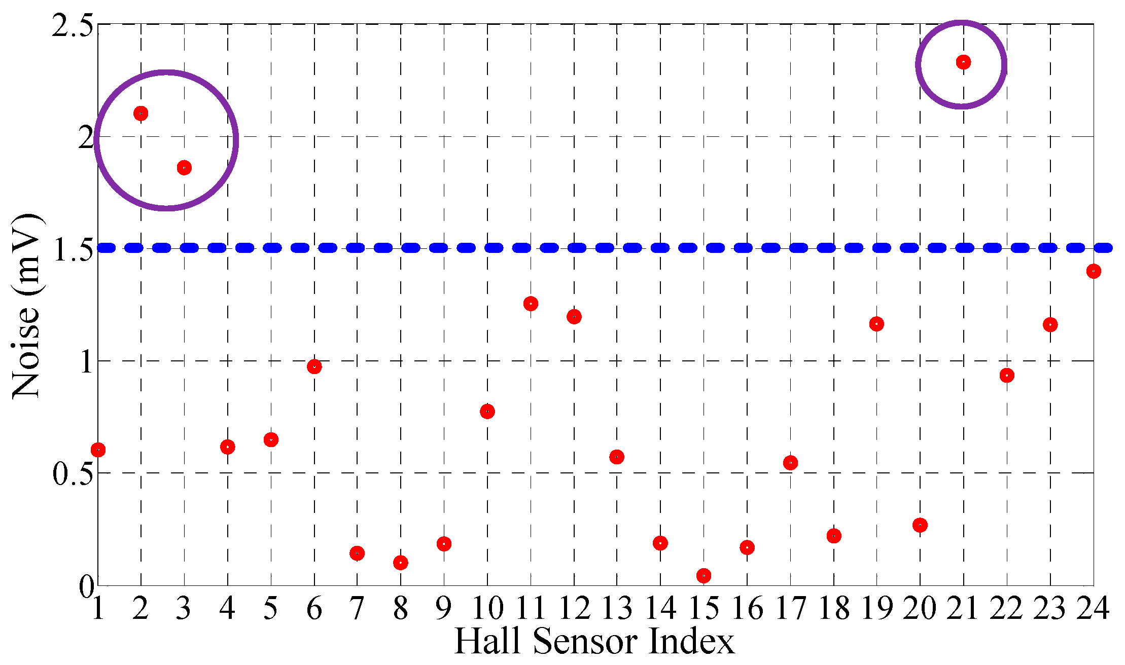
4.2.1. Sensor Module Condition Detection Function Unit
4.2.2. Current Measurement Function Unit
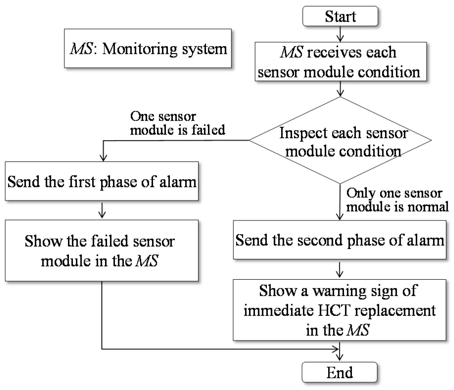
4.2.3. Sensor Module Failure Alarm Function Unit
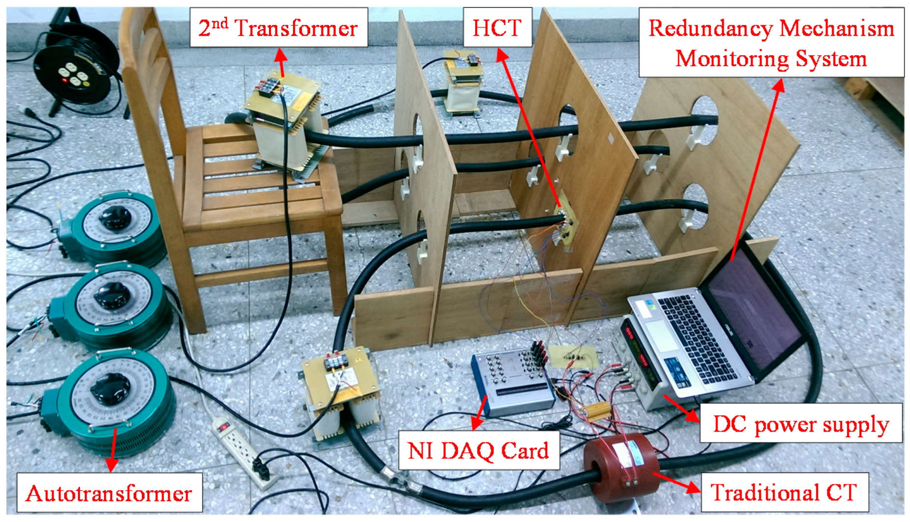
5. Measurement Results and Discussion
5.1. Single-Phase Current Measurement
5.2. Balanced Three-Phase Current Measurement
5.3. Unbalanced Three-Phase Current Measurement
6. Conclusions
Acknowledgments
Author Contributions
Conflicts of Interest
References
- Yu, Y.; Yang, J.; Chen, B. The smart grids in China—A review. Energies 2012, 5, 1321–1338. [Google Scholar] [CrossRef]
- Li, F.; Qiao, W.; Sun, H.; Wan, H.; Wang, J.; Xia, Y.; Xu, Z.; Zhang, P. Smart transmission grid: Vision and framework. IEEE Trans. Smart Grid 2010, 1, 168–177. [Google Scholar] [CrossRef]
- McDonald, J.D. Substation automation. IED integration and availability of information. IEEE Power Energy Mag. 2003, 1, 22–31. [Google Scholar] [CrossRef]
- Kasztenny, B.; Finney, D. Generator protection and CT-saturation problems and solutions. IEEE Trans. Ind. Appl. 2005, 41, 1452–1457. [Google Scholar] [CrossRef]
- Ajaei, F.B.; Sanaye-Pasand, M.; Davarpanah, M.; Rezaei-Zare, A.; Iravani, R. Compensation of the current-transformer saturation effects for digital relays. IEEE Trans. Power Deliv. 2011, 26, 2531–2540. [Google Scholar] [CrossRef]
- Cruden, A.; Richardson, Z.J.; McDonald, J.R.; Andonovic, I.; Laycock, W.; Bennett, A. Compact 132 kV combined optical voltage and current measurement system. IEEE Trans. Instrum. Meas. 1998, 47, 219–223. [Google Scholar] [CrossRef]
- Kucuksari, S.; Karady, G.G. Experimental comparison of conventional and optical current transformers. IEEE Trans. Power Deliv. 2010, 25, 2455–2463. [Google Scholar] [CrossRef]
- Ziegler, S.; Woodward, R.C.; Iu, H.H.; Borle, L.J. Current sensing techniques: A review. IEEE Sens. J. 2009, 9, 354–376. [Google Scholar] [CrossRef]
- Ibrahim, M.E.; Abd-Elhady, A.M. Differential reconstruction method for power frequency AC current measurement using Rogowski coil. IEEE Sens. J. 2016, 16, 8420–8425. [Google Scholar] [CrossRef]
- Yang, L.; Crossley, P.A.; Wen, A.; Chatfield, R.; Wright, J. Design and performance testing of a multivendor IEC61850-9-2 process bus based protection scheme. IEEE Trans. Smart Grid 2013, 5, 1159–1164. [Google Scholar] [CrossRef]
- Yun, S.Y.; Chu, C.M.; Kwon, S.C.; Song, I.K.; Choi, J.H. The development and empirical evaluation of the Korean smart distribution management system. Energies 2014, 7, 1332–1362. [Google Scholar] [CrossRef]
- Mohseni, H. The Rogowski coil principles and applications: A review. IEEE Sens. J. 2015, 15, 651–658. [Google Scholar]
- Fluri, R.; Schmid, J.; Braun, P. Applications of low power current and voltage sensors. In Proceedings of the 21st International Conference on Electricity Distribution (CIRED), Frankfurt, Germany, 6–9 June 2011.
- Popovic, R.S.; Drljaca, P.M.; Schott, C. Bridging the gap between AMR, GMR, and Hall magnetic sensors. In Proceedings of the 23rd International Conference on Microelectronics, Hammamet, Tunisia, 19–22 December 2011.
- Samimi, M.H.; Akmal, A.A.S.; Mohseni, H. Optical current transducers and error sources in them: A review. IEEE Sens. J. 2015, 15, 4721–4728. [Google Scholar] [CrossRef]
- Ripka, P. Electric current sensors: A review. Meas. Sci. Technol. 2010, 21, 1–23. [Google Scholar] [CrossRef]
- Xie, F.; Weiss, R.; Weigel, R. Giant-magnetoresistance-based galvanically isolated voltage and current measurements. IEEE Trans. Instrum. Meas. 2015, 64, 2048–2054. [Google Scholar] [CrossRef]
- Heidari, H.; Bonizzoni, E.; Gatti, U.; Maloberti, F. A CMOS current-mode magnetic hall sensor with integrated front-end. IEEE Trans. Circuits Syst. I Regul. Pap. 2015, 62, 1270–1278. [Google Scholar] [CrossRef]
- Chen, K.L.; Chen, N. A new method for power current measurement using a coreless Hall effect current transformer. IEEE Trans. Instrum. Meas. 2011, 60, 158–169. [Google Scholar] [CrossRef]
- Boero, G.; Demierre, M.; Besse, P.A.; Popovic, R.S. Micro-Hall devices: Performance, technologies and applications. Sens. Actuators A 2003, 106, 314–320. [Google Scholar] [CrossRef]
- Huang, H.; Wang, D.; Xu, Y. A monolithic CMOS magnetic Hall sensor with high sensitivity and linearity characteristics. Sensors 2015, 15, 27359–27373. [Google Scholar] [CrossRef] [PubMed]
- Huber, S.; Leten, W.; Ackermann, M.; Schott, C.; Paul, O. A fully integrated analog compensation for the piezo-Hall effect in a CMOS single-chip Hall sensor microsystem. IEEE Sens. J. 2015, 15, 2924–2933. [Google Scholar] [CrossRef]
- Jiang, J.; Makinwa, K. A hybrid multi-path CMOS magnetic sensor with 76 ppm/°C sensitivity drift. In Proceedings of the 42nd European Solid-State Circuits Conference, Lausanne, Switzerland, 12–15 September 2016.
- Ajbl, A.; Pastre, M.; Kayal, M. A fully integrated Hall sensor microsystem for contactless current measurement. IEEE Sens. J. 2013, 13, 2271–2278. [Google Scholar] [CrossRef]
- Tsai, Y.P.; Chen, K.L.; Chen, N. Design of a Hall effect current microsensor for power networks. IEEE Trans. Smart Grid 2011, 2, 421–427. [Google Scholar] [CrossRef]
- Cristaldi, L.; Ferrero, A.; Lazzaroni, M.; Ottoboni, R.T. A linearization method for commercial Hall-effect current transducers. IEEE Trans. Instrum. Meas. 2001, 50, 1149–1153. [Google Scholar] [CrossRef]
- Frick, V.; Hebrard, L.; Poure, P.; Anstotz, F.; Braun, F. CMOS microsystem for AC current measurement with galvanic isolation. IEEE Sens. J. 2003, 3, 752–760. [Google Scholar] [CrossRef]
- Chen, K.L.; Chen, Y.R.; Tsai, Y.P.; Chen, N. A novel wireless multifunctional electronic current transformer based on ZigBee-based communication. IEEE Trans. Smart Grid 2016. [Google Scholar] [CrossRef]
- Cheng, D.K. Field and Wave Electromagnetics; Addison-Wesley: Reading, MA, USA, 1989; pp. 226, 321–345. [Google Scholar]
- Scoville, J.T.; Petersen, P.I. A low-cost multiple Hall probe current transducer. Am. Inst. Phys. 1991, 62, 755–760. [Google Scholar] [CrossRef]
- Bazzocchi, R.; Rienzo, L.D. Interference rejection algorithm for current measurement using magnetic sensor arrays. Sens. Actuators A 2000, 85, 38–41. [Google Scholar] [CrossRef]
- Mlejnek, P.; Vopálenský, M.; Ripka, P. AMR current measurement device. Sens. Actuators A 2008, 141, 649–653. [Google Scholar] [CrossRef]
- Rienzo, L.D.; Zhang, Z. Spatial harmonic expansion for use with magnetic sensor arrays. IEEE Magn. 2010, 46, 53–58. [Google Scholar] [CrossRef]
- International Electrotechnical Commission. Instrument Transformers—Part 8: Electronic Current Transformers; IEC Standard 60044-8; IEC: Geneva, Switzerland, 2002. [Google Scholar]
- Allegro MicroSystems. A1301 and A1302 Datasheets; Allegro MicroSystems, Inc.: Worcester, MA, USA, 2016. [Google Scholar]


| Traditional CT | Rogowski Coil CT | OCT | LPCT | Traditional Hall-Effect CT | Proposed Hall-Effect CT | |
|---|---|---|---|---|---|---|
| Saturation problem | Yes | No | No | No | Yes | No |
| DC capable | No | No | Yes | No | No | No |
| Multifunction 1 | No | Yes | Yes | Yes | No | Yes |
| Range | A–kA | A–MA | A–MA | A–kA | mA–kA | A–MA |
| Linearity | Medium | Medium | Good | Good | Good | Good |
| Sensing structure | Simple | Simple | Complicated | Simple | Simple | Simple |
| Cost | Medium | Medium | Expensive | Medium | Medium | Low |
| Case | Sensor Module Failure | Current Error (%) | |
|---|---|---|---|
| Internal | External | ||
| 1 | 0 | 0 | 0.0000 |
| 2 | 0 | 1 | 0.0031 |
| 3 | 1 | 0 | 0.0008 |
| 4 | 0 | 2 | 0.0123 |
| 5 | 1 | 1 | 0.0038 |
| 6 | 2 | 0 | 0.0031 |
| 7 | 0 | 3 | 0.0000 |
| 8 | 1 | 2 | 0.0131 |
| 9 | 2 | 1 | 0.0062 |
| 10 | 3 | 0 | 0.0000 |
| 11 | 1 | 3 | 0.0015 |
| 12 | 2 | 2 | 0.0154 |
| 13 | 3 | 1 | 0.0061 |
| 14 | 2 | 3 | 0.0062 |
| 15 | 3 | 2 | 0.0245 |
| Case | Sensor Module Failure | Current Error (%) | IEC 60044-8 Class 0.2 (%) |
|---|---|---|---|
| 1 | 0 | 0.0810 | 0.75 |
| 2 | 1 | 0.1699 | |
| 3 | 2 | 0.4943 |
| Case | Sensor Module Failure | Current Error (%) | IEC 60044-8 Class 0.2 (%) | ||
|---|---|---|---|---|---|
| R Phase | S Phase | T Phase | |||
| 1 | 0 | 0.0809 | 0.0807 | 0.0809 | 0.75 |
| 2 | 1 | 0.1676 | 0.1672 | 0.1675 | |
| 3 | 2 | 0.4850 | 0.4844 | 0.4849 | |
| Case | Sensor Module Failure | Maximum Composite Error among Three Phases (%) | IEC 60044-8 Class 5P30 (%) |
|---|---|---|---|
| 1 | 0 | −0.02 | 5 |
| 2 | 1 | −0.17 | |
| 3 | 2 | 0.2 |
| Accuracy Class | Percentage Current Error (%) at Percentage of Rated Current Shown Below | |||
|---|---|---|---|---|
| 5% | 20% | 100% | 120% | |
| Class 0.2 of IEC Standard 60044-8 | ±0.75 | ±0.35 | ±0.2 | ±0.2 |
| Class 0.5 of IEC Standard 60044-8 | ±1.5 | ±0.75 | ±0.5 | ±0.5 |
| Measurement result of each sensor module | ||||
| Sensor module 1 | 1.118 | 0.276 | −0.00 | −0.10 |
| Sensor module 2 | 0.710 | 0.511 | −0.00 | −0.10 |
| Sensor module 3 | 0.391 | 0.410 | −0.01 | −0.11 |
| Sensor module failure | Proposed HCT with redundancy mechanism | |||
| 0 | 0.740 | 0.399 | −0.00 | −0.10 |
| 1 | 0.914 | 0.393 | −0.00 | −0.10 |
| 2 | 1.118 | 0.276 | −0.00 | −0.10 |
| Percentage Current Error (%) at 100% of Rated Current | |
|---|---|
| Measurement result of each sensor module | |
| Sensor module 1 | −0.02 |
| Sensor module 2 | −0.01 |
| Sensor module 3 | −0.01 |
| Sensor module failure | Proposed HCT with redundancy mechanism |
| 0 | −0.01 |
| 1 | −0.02 |
| 2 | −0.02 |
| Current | Scenario 1 | Scenario 2 | Scenario 3 |
|---|---|---|---|
| R-Phase Current (A) | 600 | 300 | 150 |
| S-Phase Current (A) | 300 | 150 | 600 |
| T-Phase Current (A) | 150 | 600 | 300 |
| Percentage current error (%) | |||
| Measurement result of each sensor module | |||
| Sensor module 1 | −0.03 | −0.07 | −0.38 |
| Sensor module 2 | −0.02 | 0.68 | 1.12 |
| Sensor module 3 | −0.03 | 0.26 | 0.32 |
| Sensor module failure | Proposed HCT with redundancy mechanism | ||
| 0 | −0.02 | 0.29 | 0.35 |
| 1 | −0.03 | 0.30 | 0.36 |
| 2 | −0.03 | −0.07 | −0.38 |
© 2017 by the authors. Licensee MDPI, Basel, Switzerland. This article is an open access article distributed under the terms and conditions of the Creative Commons Attribution (CC BY) license ( http://creativecommons.org/licenses/by/4.0/).
Share and Cite
Chen, K.-L.; Wan, R.-S.; Guo, Y.; Chen, N.; Lee, W.-J. A Redundancy Mechanism Design for Hall-Based Electronic Current Transformers. Energies 2017, 10, 312. https://doi.org/10.3390/en10030312
Chen K-L, Wan R-S, Guo Y, Chen N, Lee W-J. A Redundancy Mechanism Design for Hall-Based Electronic Current Transformers. Energies. 2017; 10(3):312. https://doi.org/10.3390/en10030312
Chicago/Turabian StyleChen, Kun-Long, Ren-Shuo Wan, Yi Guo, Nanming Chen, and Wei-Jen Lee. 2017. "A Redundancy Mechanism Design for Hall-Based Electronic Current Transformers" Energies 10, no. 3: 312. https://doi.org/10.3390/en10030312
APA StyleChen, K.-L., Wan, R.-S., Guo, Y., Chen, N., & Lee, W.-J. (2017). A Redundancy Mechanism Design for Hall-Based Electronic Current Transformers. Energies, 10(3), 312. https://doi.org/10.3390/en10030312