Influence of Different Types of Obstacles on the Propagation of Premixed Methane-Air Flames in a Half-Open Tube


1
School of Chemical Engineering, Anhui University of Science & Technology, Huainan 232001, China
2
Postdoctoral Mobile Research Station for Civil Engineering, Anhui University of Science & Technology, Huainan 232001, China
3
Process Safety and Disaster Prevention Laboratory, National Yunlin University of Science and Technology, Douliu, Yunlin 64002, Taiwan
4
Safety Engineering Technology Institute, Anhui Province Academy of Science and Technology, Hefei 230061, China
*
Authors to whom correspondence should be addressed.
Energies 2017, 10(11), 1908; https://doi.org/10.3390/en10111908
Submission received: 21 October 2017
/
Revised: 15 November 2017
/
Accepted: 17 November 2017
/
Published: 20 November 2017
Abstract
:To understand the propagation characteristics of methane-air deflagration flames and in an obstacle-filled tube, a high-speed color video camera, photoelectric sensors, and pressure transducers were used to test the deflagration flame propagating parameters. The tests were run in a 1500 mm long plexiglass tube with a 100 × 100 mm square cross-section. The obstacles included four types of repeated baffles and five forms of solid structure obstacles. The results showed that: (1) the flame front was constantly distorted, stretched, and deformed by different types of obstacles and, consequently, the flame propagating parameters increased; (2) plates and triple prisms increased the speed of the flame and overpressure to the highest extent, whereas cuboids and quadrangulars exerted an intermediate effect. However, the effect of cylindrical obstacles was comparatively limited. It was suggested that the obstacle’s surface edge mutation or curvature changes were the main factors stimulating the flame acceleration; (3) the peak pressure of deflagration was relatively low near the ignition end, increased gradually until it reached the maximum at the middle of the tube, and decreased rapidly near the open end; and (4) the fixed obstacles in front of the flame exhibited a blocking effect on flame propagation during the initial stages; the flame speed and overpressure increased when the flame came into contact with the obstacles. This study is of significance because it explains the methane-air propagation mechanism induced by different types of obstacles. The findings have value for preventing or controlling gas explosion disasters.
1. Introduction
Underground mining accounts for more than 90% of coal mining in China. At a greater mining area and depth, the coal seam containing methane is generally larger. At present, more than 30% of mines are gassy mines facing high risk of explosions and are sites of frequent accidents [1,2]. According to the statistics provided by the Chinese government, 24 major accidents occurred in coal mines, killing 3780 people since the founding of the People’s Republic of China in 1949. Of these 24 accidents, 21 were related to fire damp explosions, including gas and coal dust explosions, and the number of deaths in such cases is 3424. Apart from the loss of life, society incurred substantial property losses [3,4,5,6].
Accidents related to gas or gas and coal dust explosion occur frequently and are mostly attributed to inferior management, lack of safety consciousness, and improper prevention measures. Furthermore, the current technologies for preventing and suppressing accidents are inadequate. Some gas explosion suppression devices, such as flameproof devices and water bags, have been fixed on the roadways in some large and medium-sized state-owned coal mines; however, gas explosions still occur. This implies that these devices often fail in yielding the desired results. One of the reasons behind such failures might be that many people do not completely understand the mechanisms of fire damp explosion and flame propagation or flame propagation characteristics [7,8]. Furthermore, all the electrical equipment and mining machinery installed in coal mine roadways act as obstacles and can induce flame acceleration, thus causing even more severe damage. Thus, studying the phenomena and laws of methane-air deflagration flame propagation in the presence of obstacles is of practical importance.
Simulation roadways or small-scale experiment tubes have often been used to conveniently investigate the phenomena of gas explosions. Even though large-scale simulation laneways are more similar to actual coal mine roadways, their high cost, space requirements, and difficulty in parameter testing impose several restrictions. Therefore, many researchers have preferred to set up small-scale experiment tubes to study the flame propagation process of gas explosion using advanced digital electrical and optical measurement technologies [5,8,9,10,11]. The methane-air flame acceleration mechanism and deflagration wave propagation characteristics under the two conditions are similar and they exhibit a “size-effect” relationship [5,12].
The propagation of methane-air flames and those with other combustible gases in the presence of obstacles in a tube is a complex process involving gas flow, heat transfer, and radiation. The major influencing factors are the obstacle size and number, the types of gases, and the material composition of the tube. Obstacle-induced flame propagation attracted research attention quite early. In 1926, Chapman and Wheeler [13] found that obstacles can accelerate the propagation of a flame in a tube. Lee [14] carried out amount of investigations on flame acceleration in obstacle-filled tubes and its quasi-steady deflagration. Since then, numerous studies have investigated obstacle-induced flame acceleration in a tube, especially with planar obstacles (such as a barrier film, thin ring, or thin fan-shaped plate) [15,16,17,18,19,20,21] and solid structure obstacles (such as a wedge or rectangular or triangular prism body) [22,23,24,25,26]. However, more reports are available on planar obstacles than on solid structure obstacles, even though the latter have more practical significance.
In this study, planar obstacles, namely four types of repeated baffles, and five types of solid structure obstacles with three blockage ratios (i.e., 15 forms of obstacles) were used. The premixed methane-air flames propagating processes induced by obstacles were discussed and analyzed via recording the flame propagating velocities and deflagration pressures. The flame propagating parameters were related with the obstacles’ surface irregularities and the high-speed camera images for flame movement. Thus, the influence of different types of obstacles on the propagation process of premixed methane-air flames in an obstacle-filled tube was studied systematically and comprehensively.
2. Materials and Method
The experimental tube was an organic glass flame accelerating tube designed by the Anhui University of Science and Technology, China; the tube was 1500 mm long with a 100 × 100 mm square cross-section. The ignition end of the tube was closed, and the other end was loosely covered with a single layer of polyethylene film. The system was composed of a gas mixing device, ignition device, photoelectric sensors, pressure transducers, a data acquisition device, and obstacles. The experimental system is illustrated in Figure 1.
2.1. Gas Mixing Device
According to Dalton’s partial pressure law, premixed methane-air gas of the required concentration was prepared using a special gas mixing device. Moreover, the precise volume concentration was measured using a CJG-type optical interferometric methane detector. The methane volume concentrations used in this study were 9.47% and 10.50%. The tube was pumped with the premixed gas after it was pumped with vacuum until the pressure returned to normal (1 atm), and the open end was loosely covered with a single layer of polyethylene film. This system was then used for experimentation. The gas mixing device is shown in Figure 2.
2.2. Ignition Device
The ignition system consisted of a simple capacitive energy storage spark ignition device. The exact spark energy value was measured using a special instrument. For convenience, the nominal ignition energy can be used to reflect the ignition energy according to the following formula:
where E is the nominal ignition energy (J), C is the ignition capacitance (F), and U is the capacitor discharge voltage (V).
Based on the calculations, the nominal ignition energy was 14 J, and the actual ignition energy was 250–500 mJ.
2.3. Photoelectric Sensors
Photoelectric sensors were fabricated using an infrared sensitive photodiode. The response time of the photodiode is <0.1 μs, the photocurrent is >2.0 mA, and the dark current is <0.3 μA. This photodiode meets all the requirements of this investigation and could be used to capture the flame signals. The photoelectric sensors were arranged at distances of 0, 51, 319, 589, 862, 1130, and 1405 mm from the ignition end. Measurement points 1–7 are shown in Figure 1.
2.4. Pressure Transducers
Six piezoelectric pressure sensors (Model CY-YD-203, Sinocera Piezotronics, Inc., Yangzhou, China) were arranged on the tube. The sensors were fixed at distances of 51, 319, 589, 862, 1130, and 1405 mm from the ignition end. During installation, the sensitive faces of the sensors were kept flush with the tube inner wall. Measurement points 8–13 are shown in Figure 1. The pressure transducers were dynamically calibrated in a shock tube before measurement.
2.5. Data Acquisition Device
The flame sensor signals were directly recorded using a digital storage recorder (8841, HIOKI Trading Co., Ltd., Nagano, Japan). The pressure sensor signals were initially amplified using a charge amplifier (YE5853A, Sinocera Piezotronics, Inc., Yangzhou, China) and then recorded by the HIOKI 8841. The data recorder had 16 independent channels and 12 ranges, and its resolution was 1/80 of the measurement range. The sampling rate was up to 1.0 MHz, and the record display speed was set at 25 mm/s.
2.6. Obstacles
The obstacles used in the experiments were planar obstacles (i.e., repeated baffles P1–P4) and solid structure obstacles (i.e., plate baffles S1–S3, rectangular obstacles Cu1–Cu3, triangular prism obstacles T1–T3, quadrangular prism obstacles Q1–Q3, and cylindrical obstacles Cy1–Cy3).
The planar repeated baffles were fabricated using 1-mm thick rectangular copper sheets welded to two steel wires. The numbers of planar baffles were five and seven, and the blockage ratios were 10% and 20%; the distance between the first baffle and the ignition end was 150 mm. The appearance and placement of the obstacles are delineated in Figure 3a.
The solid structure obstacles were fabricated using wood coated with a fire retardant material after machining. The blockage ratio was 20%, 40%, or 60%, depending on the type of the solid structure obstacle (five types). The distance from the first baffle to the ignition end was 190 mm. The appearance and placement of the obstacles are shown in Figure 3b. For intuitive representation, the obstacles with varying blockage ratios are depicted in one figure. The size of each obstacle is shown in Table 1.
3. Results and Discussion
3.1. Analysis of High-Speed Images of Methane-Air Premixed Flame Propagation in the Tube with Different Types of Obstacles
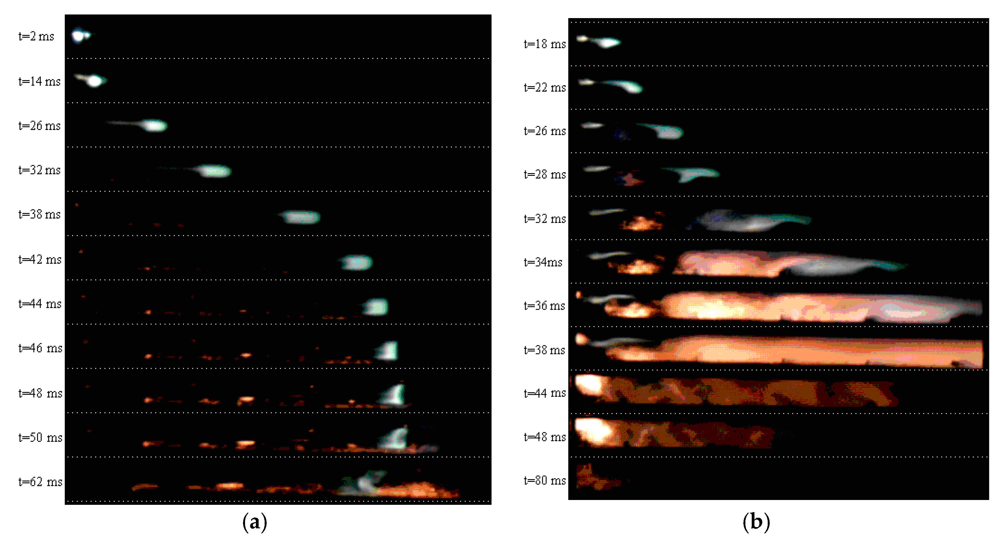
High-speed camera photographs of the propagation of 9.47% CH4 (by volume) premixed flames without obstacles are shown in Figure 4a. The figure was formed by combining a series of typical photographs cut into the same size according to a fixed proportion. The mixture gas was ignited at t = 2 ms, and the shape of the flame resembled a gourd. The flame front curvature gradually became smaller at t = 14–42 ms, and the outline of the flame resembled a tadpole. The flame front resembled a plane at t = 44 ms. Later, the flame front gradually became concave with respect to the burnt area at t = 46–62 ms. The flame surface curvature gradually became larger, forming a “V” shape; meanwhile, it exhibited a backdraft phenomenon. There was only a faint light-emitting region throughout the tube at t = 80 ms; at this moment, the combustion reaction was essentially complete.
High-speed camera photographs of the propagation of 9.47% CH4 premixed flames with repeated baffles (P2) are depicted in Figure 4b. Overall, the light-emitting area became brighter and the flame propagation velocity increased. However, the fuel combustion duration was approximately the same as that in the condition without obstacles. The fuel was ignited at t = 2 ms and the contour of the flame resembled a gourd. The flame began to cross the first baffle sheet at t = 18 ms. At t = 22–26 ms, the flame completely crossed the first baffle sheet, and a blue light emission region appeared near the barrier sheet. At t = 28–36 ms, the flame sequentially crossed the second to fifth baffle sheets. The flame propagation speed increased substantially faster under conditions of barrier plurality than when there were no obstacles. The flame luminous zone filled the entire tube at t = 38 ms; subsequently, the combustion light-emitting zone contracted toward the ignition end. The combustion reaction was essentially complete at t = 80 ms.
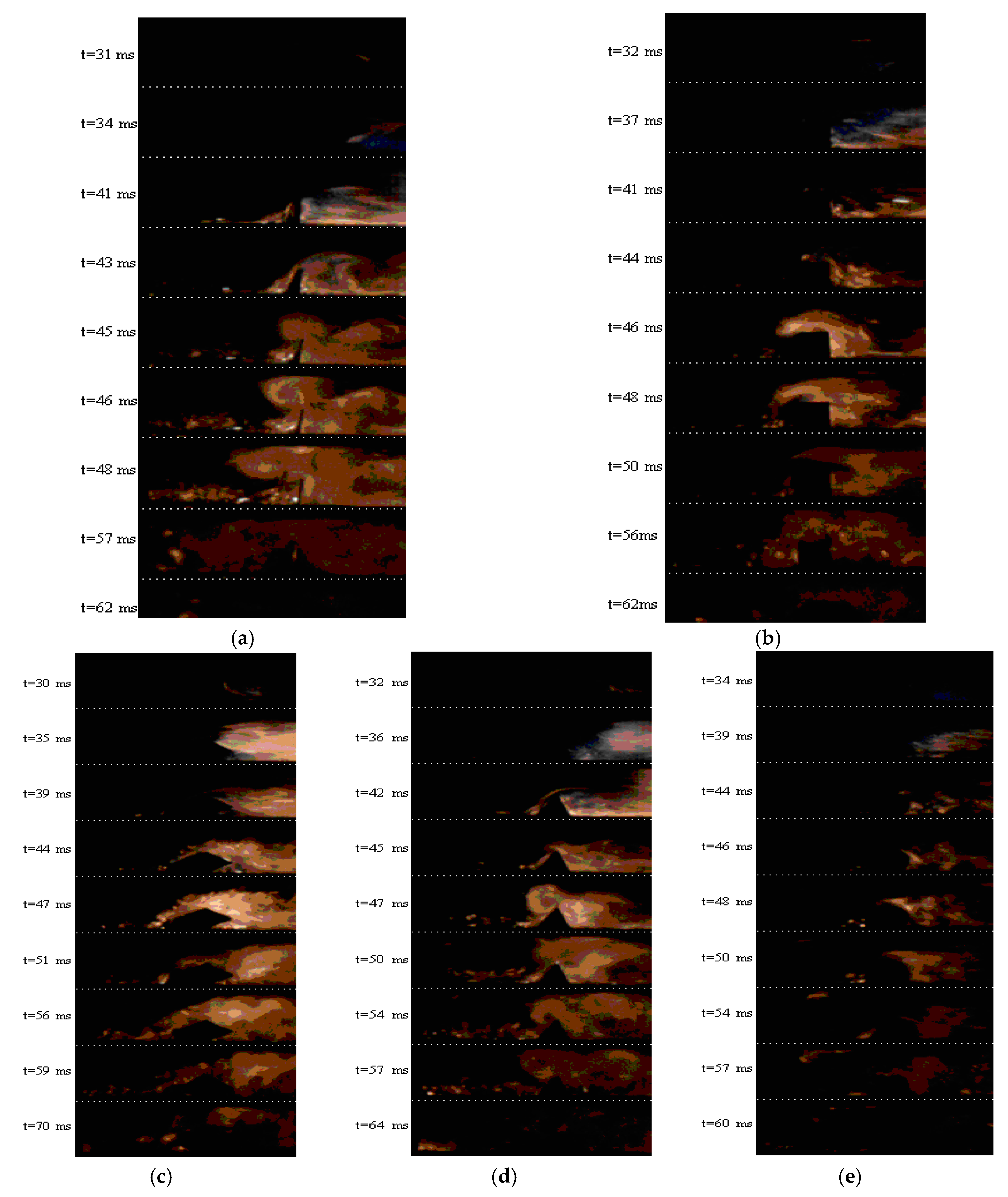
High-speed video camera images of the interactions between premixed flames and the five types of solid structure obstacles are shown in Figure 5, which was formed by combining a series of typical photographs cut to the same size according to a fixed proportion. The flames began to cross the solid structure obstacles at 30–34 ms after ignition. Large-scale eddies were evident at the front and back of the plate obstacle. In addition, counterclockwise and clockwise vortices formed upstream and downstream of the obstacle at t = 45–48 ms. Vortices with opposite motion formed at the front and back of the triangular prism obstacle at t = 47–54 ms. Such vortices also formed around the rectangular and quadrangular obstacles, but they were not highly visible. By contrast, the vortices induced by the cylindrical obstacles were the weakest, and the flame light-emitting region was the darkest.
These phenomena can be explained on the basis of the obstacle surface characteristics. The curvature changes or smoothness of the surfaces of the obstacles were the main factors influencing flame acceleration. When the angle between two typical planes on the obstacle surface was acute (in Figure 5, the angle for the triangular prism obstacle is 60°, whereas that of the plate obstacle is assumed to be 0°), large-scale eddies easily formed after the flame crossed the obstacles, and the contours of the vortices observed in the high-speed camera images were clear. The presence of such large-scale eddies can increase the degree of turbulence and accelerate flame propagation. Relatively small eddies formed after the flame crossed those obstacles whose surface profiles contained a right angle or an obtuse angle (in Figure 5, the angles corresponding to the cuboid, quadrangular prism, and cylinder are 90°, 120°, and 180°, respectively); however, the obstacle outline could not be clearly observed in the high-speed camera photographs. Furthermore, these smaller-scale eddies could induce flame acceleration to a lesser degree. The outer surface of the cylindrical obstacle was smooth, which led to a low flame acceleration effect. The images also illustrate that the type of obstacle had a smaller influence on initial flame propagation. Only when the flame crosses the obstacles can discrepancies in the flame propagation velocity be observed.
3.2. Analysis of Methane-Air Premixed Flame Propagation Velocity in the Tube with Different Types of Obstacles
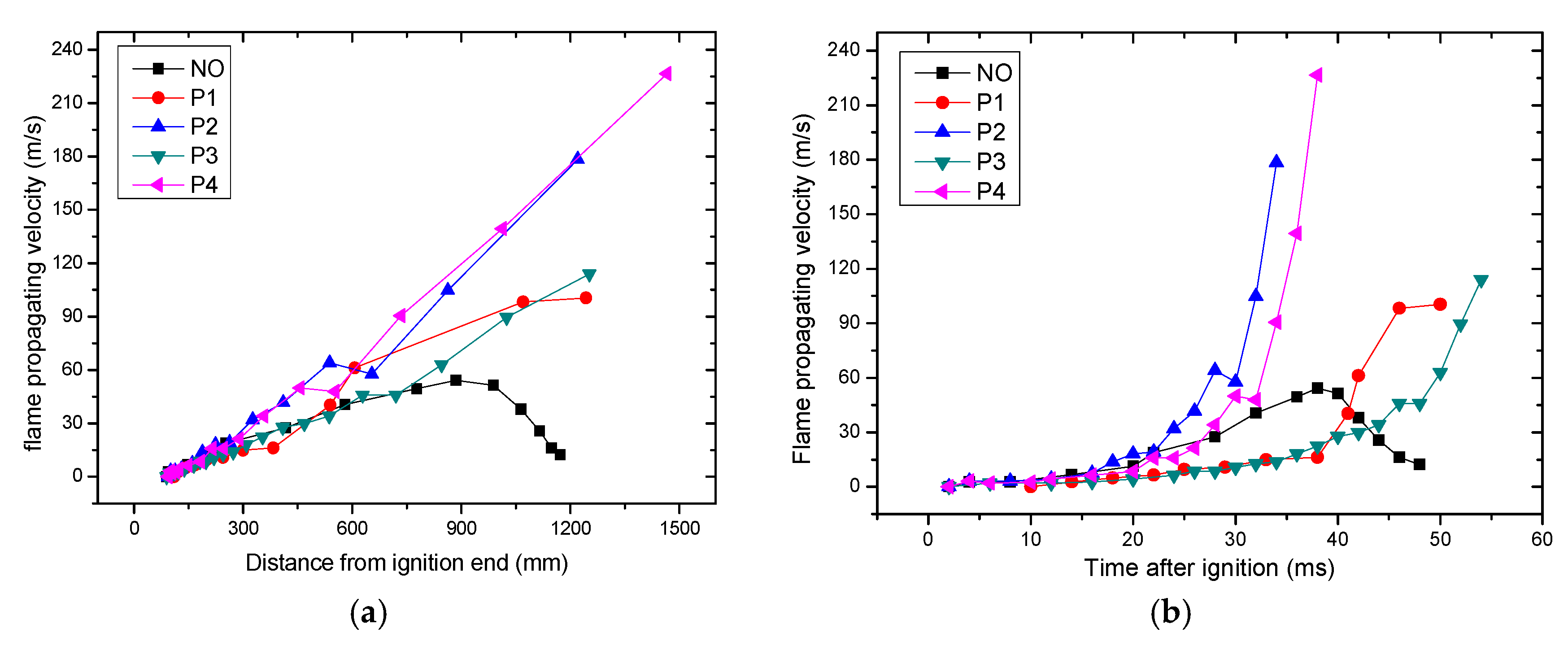
Figure 6a depicts the relationship between the average flame propagation velocity and the ignition distance under a no obstacle condition for 9.47 vol % CH4, and Figure 6b illustrates the relationship between the average flame propagation velocity and the ignition time under similar conditions. The average flame propagation velocity is calculated by dividing the actual flame front distance of two adjacent high-speed camera photographs by a single frame time interval. Figure 6 demonstrates that the acceleration effect was not obvious in the early stages of flame propagation (t < 15 ms, L < 300 mm), regardless of the use of obstacles. Figure 6a,b indicates that the sheet obstacles P2 and P4 exerted a greater flame acceleration effect than the sheet obstacles P1 and P3. Their velocities were in the following order: VP4 > VP2 > VP3 > VP1 > VNO. The results illustrate that the contribution of the blockage ratio of repeated baffles to flame propagation acceleration was greater than of the number of, and spacing between, the barrier sheets.
Figure 6c–h delineates the relationship between the average flame propagation velocity and the ignition distance or ignition time with different types of solid structure obstacles at 10.50 vol % CH4; the blockage ratios were 20%, 40%, and 60%. The average flame propagation velocities were obtained by dividing the distance between two adjacent photoelectric sensors by the time required for the flame to pass the two sensors.
Figure 6c–h also shows that a single solid structure obstacle in the tube can accelerate methane-air flame propagation to a large extent. The degree of acceleration varied between types of obstacles; the largest effect was exerted by the flat and triangular prism obstacles, the rectangular and quadrangular obstacles exerted an intermediate effect, and the cylindrical obstacles exerted the smallest effect. This is due to the mutation edges (when the angle between two typical edges <90°) on the surfaces of the flat and triangular prism obstacles distorting the flame front, thus increasing the degree of combustion turbulence and the flame propagation velocity. By comparison, the surface of the cylindrical obstacle was smooth without any mutation edges and angularities; thus, the flame front was not distorted, and the flame propagation velocity was lower. The outer surfaces of the rectangular and quadrangular obstacles contained moderate mutation edges or angularities (the angle between two typical edges is >90°) and, hence, the flame propagation velocity was intermediate. These results demonstrate that mutation edges or irregularities on the surfaces of solid structure obstacles greatly accelerated flame propagation, whereas obstacles with a smooth surface accelerated flame propagation only to a low extent. In addition, with an increase in the obstacle blockage ratio, the flame propagation velocity increased, but the degree to which it increased was dependent on the type of obstacle.
3.3. Analysis of the Flame Pressure Distribution When Different Types of Obstacles Were Placed in the Tube
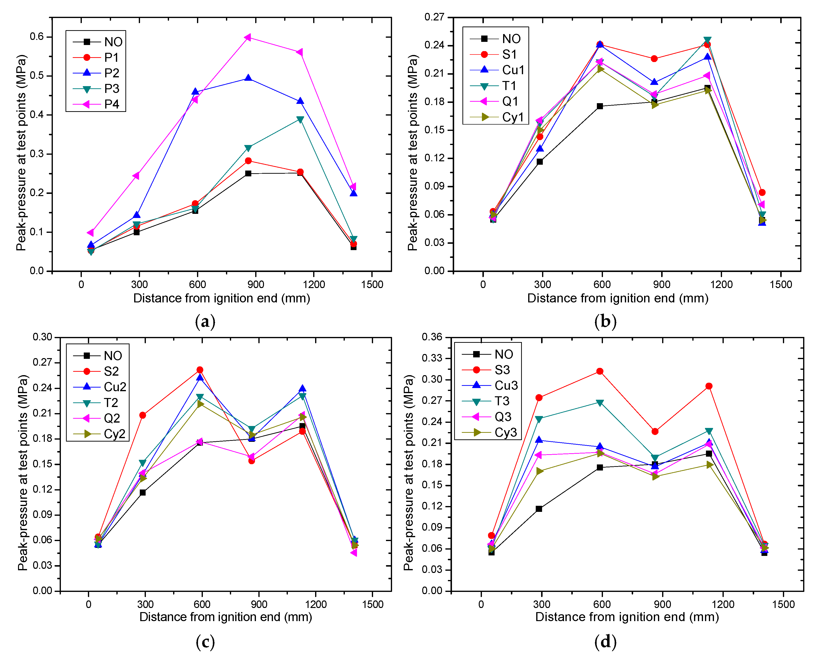
Figure 7a discloses the relationship between the peak pressure distribution and the ignition distance at each testing point for the propagation of 9.47 vol % CH4 flames with or without repeated baffles in the tube. The peak pressure distribution exhibited the order Pmax (P4) > Pmax (P2) > Pmax (P3) > Pmax (P1) > Pmax (NO), which is consistent with the order of the flame propagation velocity (Figure 6a). As mentioned earlier, the greater the flame propagation velocity, the greater the combustion pressure acting on the tube inner wall is. Furthermore, the peak pressure was low during the initial stages of flame propagation (near the ignition end), after which it gradually increased as the flame moved forward; the maximum pressure was observed at a point approximately two-thirds of the distance along the tube from the ignition end. Later, the peak pressure declined swiftly near the open end under the loosely covered condition.
Figure 7b–d illustrates the relationship between the peak pressure at each testing point and the ignition distance during the propagation of 10.50% CH4 flames with different solid obstacles that had blockage ratios of 20%, 40%, and 60%. Fixing a single solid structure obstacle in the tube led to different degrees of increase in the peak pressure at each testing point. The highest peak pressure was obtained with the flat and the triangular prism obstacles, the rectangular and quadrangular obstacles led to an intermediate peak pressure, and the peak pressure obtained with cylindrical obstacles was the lowest. This order is similar to that of the flame propagation velocity (Figure 6c–h), and the reasons for such phenomena are similar. Figure 7b–d shows that the curve depicting the relationship between the peak pressure and the ignition distance curve was “M”-shaped at each testing point. The combustion pressure in the tube exhibited a pulsation phenomenon. Moreover, with an increase in the obstacle blockage ratio, the combustion pressure at each testing point increased; the contribution of repeated baffles to the flame peak pressure was much larger than that of a single solid structure obstacle. In addition, the pressure at the open end decreased obviously in each case.
3.4. Further Discussion and Remarks
In the paper, we designed 20 groups of experiments to study the propagation characteristics for methane-air deflagration flames with or without obstacles. In order to get reliable data, each group has at least three repeated tests, and has a total of more than 60 experiments. Based on a lot of experiments, we systematically obtained the flame propagation laws induced by different obstacles, not only for planar obstacles, but also stereo-structure obstacles. It was suggested that the obstacle’s surface edge mutation or curvature changes were the main factors for stimulating flame acceleration. Furthermore, flame acceleration was related to the edge angle of stereo-structure obstacles, and the angles for plate, triangular prism, cuboid, quadrangular prism and cylinder are 0°, 60°, 90°, 120°, and 180°, respectively. The acute angle’s situations have more stimulating effects than the obtuse angle’s. The tube was made of transparent plexiglass material, which was convenient to observe the whole process of flame movement. Certainly, the vortices formed around the obstacles are closely related to the flame propagation, which can be clearly seen from the images of high speed video camera. Many reports mainly focused on repeated baffles or a single obstacle influencing on flame acceleration [14,15,17,19,20]. However, the flame propagating parameters were related with the obstacles surface irregularities and the high-speed camera images for whole flames movement. The experimental and analysis results of this study can serve as a valuable reference in preventing explosion accidents related to mine gases and other combustible gases.
4. Conclusions
(1) The flame propagating parameters were increased due to different types of obstacles.
The flame front was constantly distorted, stretched, and deformed by the repeated baffles or solid structure obstacles and, consequently, the flame propagation velocity increased. Large-scale vortices formed near the plate obstacles; counterclockwise vortices formed in the obstacle upstream, whereas clockwise vortices formed in the obstacle downstream. The presence of repeated baffles inside the tube can significantly increase the propagation velocity of the methane-air premixed flame and its peak deflagration pressure. Furthermore, the contribution of the blockage ratio of repeated baffles to increases in flame propagation velocity and peak deflagration pressure was greater than those of the number of and spacing between the barrier sheets.
(2) Solid structure obstacles’ shapes or irregularities determined the flame acceleration.
A single solid structure obstacle placed inside the tube led to different degrees of increase in the velocity of the methane-air premixed flame and peak deflagration pressure. Compared with propagation in the no obstacle situation, the extent of flame propagation acceleration varied depending on the type of the obstacle. The order is summarized as follows: flat and triangular > rectangular and quadrangular > cylindrical. Mutation edges or irregularities on the surfaces of the solid structure-type obstacles greatly accelerated flame propagation, whereas obstacles with smooth surfaces induced flame acceleration to a lesser extent.
(3) The deflagration pressures distribution in obstacles-filled tube revealed a certain regularity.
The peak pressure inside the tube was the lowest in the initial stages of flame propagation (near the ignition end). It gradually increased as the flame propagated forward, and the maximum pressure was observed at a point located at approximately two-thirds of the distance along the tube from the ignition end. The peak pressure later declined rapidly near the open end. The flame propagation velocity was lower in the initial stages of flame propagation when the flame was blocked by the first baffle in a set of repeated obstacles or solid structure obstacles. However, when the flame crossed the obstacles, there was a positive feedback effect on the turbulent combustion induced by the obstacles, and the flame propagation velocity increased promptly.
It should be a deep theoretical analysis on flame propagation with numerical simulation method for the next further work. Based on dimensional analysis, obstacles’ shape coefficients can be connected with the premixed flame propagating parameters. A high-speed Schlieren system should be established to record the deflagration wave front’s profile in a transparent tube in the future.
Acknowledgments
This study was supported by National Natural Science Foundation of China (No. 11502001), China Postdoctoral Science Foundation Funded Project (No. 2014M561808), Postdoctoral Science Foundation Funded Project in Anhui Province (No. 2014B035), the authors expressed their sincere gratitude here.
Author Contributions
All authors have contributed significantly to this work.
Conflicts of Interest
The authors declare no conflict of interest.
References
- Sun, L.T.; Jiang, B.Y.; Gu, F.J. Effects of changes in pipe cross-section on the explosion-proof distance and the propagation characteristics of gas explosions. J. Nat. Gas Sci. Eng. 2015, 25, 236–241. [Google Scholar] [CrossRef]
- Yuan, L. Exploit coal and gas simultaneously, lead scientific coal exploration. Energy Conserv. 2011, 4, 11. [Google Scholar]
- Liu, Y.; Sun, J.H.; Chen, D.L.; Chen, X.F.; Wang, Q.S. On lower limit of explosive coal dust in coal dust mixture with methane. J. Saf. Environ. 2007, 7, 129–131. [Google Scholar]
- Sun, J.Q. Research of integrated method of prevention and control of gas. Ind. Mine Autom. 2011, 2, 1–5. [Google Scholar]
- Wang, Q. Study on the Methane–Air Deflagration Flames Propagation Characteristics in an Square Plexiglass Tube. Ph.D. Thesis, University of Science and Technology of China, Heifei, China, 2013. [Google Scholar]
- Pan, R.K.; Xiao, Z.J.; Yu, M.G. The characteristics of methane combustion suppression by water mist and its engineering application. Energies 2017, 10, 1566. [Google Scholar] [CrossRef]
- Silvestrini, M.; Genova, B.; Parisi, G.; Leon Trujillo, F.J. Flame acceleration and DDT run-up distance for smooth and obstacles filled tubes. J. Loss Prev. Process Ind. 2008, 21, 555–562. [Google Scholar] [CrossRef]
- Yu, M.G.; Zheng, K.; Chu, T.X. Gas explosion flame propagation over various hollow-square obstacles. J. Nat. Gas Sci. Eng. 2016, 30, 221–227. [Google Scholar] [CrossRef]
- Guo, Z.R.; Shen, Z.W.; Lu, S.X.; Zhou, N. The experimental of methane–air flame propagation in the tube with quadrate cross section. J. Coal Sci. Eng. 2005, 11, 60–63. [Google Scholar]
- Lu, S.X.; Guo, Z.R.; Li, Y.L.; Fan, W.C.; Zhang, L.; Yang, L.Z. Experimental and theoretical analysis of acceleration of a gas flame propagating over a dust deposit. Proc. Combust. Inst. 2002, 29, 2839–2846. [Google Scholar] [CrossRef]
- Nie, B.S.; He, X.Q.; Zhang, R.M.; Chen, W.X.; Zhang, J.F. The roles of foam ceramics in suppression of gas explosion overpressure and quenching of flame propagation. J. Hazard. Mater. 2011, 192, 741–747. [Google Scholar] [CrossRef] [PubMed]
- Xu, J.D.; Zhou, X.Q.; Wu, B. Study on the size effect in the propagation of gas explosion in mine pit. China Saf. Sci. J. 2001, 11, 36–40. [Google Scholar]
- Chapman, W.R.; Wheeler, R.V. The propagation of flame in mixtures of methane and air, Part IV: The effect of restrictions in the path of the flame. J. Chem. Soc. 1927, 12, 309–312. [Google Scholar] [CrossRef]
- Lee, J.H.S.; Knystautas, R.; Chan, C.K. Turbulent flame propagation in obstacle-filled tubes. Symp. (Int.) Combust. 1985, 20, 1663–1672. [Google Scholar] [CrossRef]
- Ciccarelli, G.; Fowler, C.J.; Bardon, M. Effect of obstacle size and spacing on the initial stage of flame acceleration in a rough tube. Shock Waves 2005, 14, 161–166. [Google Scholar] [CrossRef]
- Dong, C.J.; Bi, M.S.; Zhou, Y.H. Effects of obstacles and deposited coal dust on characteristics of premixed methane–air explosions in a long closed pipe. Saf. Sci. 2012, 50, 1786–1791. [Google Scholar] [CrossRef]
- Fedorov, A.V. Some phenomena during flame propagation in a half-open channel with an obstacle. Shock Waves 2003, 39, 509–512. [Google Scholar] [CrossRef]
- Kent, J.E.; Masri, A.R.; Starner, S.H. A new chamber to study premixed flame propagation past repeated obstacles. In Proceedings of the 5th Asia-Pacific Conference on Combustion, The University of Adelaide, Adelaide, Australia, 17–20 July 2005; pp. 173–176. [Google Scholar]
- Moen, I.O.; Donato, M.; Knystautas, R.; Lee, J.H. Flame acceleration due to turbulence produced by obstacles. Combust. Flame 1980, 39, 21–32. [Google Scholar] [CrossRef]
- Na’inna, A.M.; Phylaktou, H.N.; Andrews, G.E. Explosion flame acceleration over obstacles Effects of separation distance for a range of scales. Proc. Saf. Environ. Prot. 2017, 107, 309–316. [Google Scholar] [CrossRef]
- Wang, Q.; Guo, Z.R.; Li, Z.M.; Ding, Y.B. Test on flame spreading characteristics of premixed methane–air in tube. Coal Sci. Technol. 2007, 35, 95–97. [Google Scholar]
- Ding, Y.B.; Xiao, F.Q.; Xuan, X.Y.; Dang, H.B.; Cui, X.; Guo, Z.R. Deposited manner of solid structure obstacles influence on flame propagation in premixed-methane tube. J. China Coal Soc. 2012, 37, 137–140. [Google Scholar]
- Ibrahim, S.S.; Masri, A.R. The effects of obstructions on overpressure resulting from premixed flame deflagration. J. Loss Prev. Process Ind. 2001, 14, 213–221. [Google Scholar] [CrossRef]
- Masri, A.R.; Ibrahim, S.S.; Nehzat, N.; Green, A.R. Experimental study of premixed flame propagation over various solid obstructions. Exp. Therm. Fluid Sci. 2000, 21, 109–116. [Google Scholar] [CrossRef]
- Naamansen, P.; Baraldi, D.; Hjertager, B.H.; Solberg, T.; Cant, S. Solution adaptive CFD simulation of premixed flame propagation over various solid obstructions. J. Loss Prev. Process Ind. 2002, 15, 189–197. [Google Scholar] [CrossRef]
- Ye, J.F.; Chen, Z.H.; Fan, B.C. Interaction between the wedge obstacle and flame. Fire Saf. Sci. 2005, 14, 246–250. [Google Scholar]
Figure 1.
Schematic of the experimental system.
Figure 2.
Schematic of the gas mixing device. (1) Pure methane; (2) compressed air bottle; (3) mixed gas bottle; (4) high pressure chamber; (5) vacuum pump; (6) vacuum meter; (7) pressure gauge; (8) gate valve; (9) hand valve; (10) bracket; and (11) gas delivery pipe.
Figure 2.
Schematic of the gas mixing device. (1) Pure methane; (2) compressed air bottle; (3) mixed gas bottle; (4) high pressure chamber; (5) vacuum pump; (6) vacuum meter; (7) pressure gauge; (8) gate valve; (9) hand valve; (10) bracket; and (11) gas delivery pipe.

Figure 3.
Arrangement methods for various obstacles: (a) planar type repeated baffles; and (b) solid structure obstacles.
Figure 3.
Arrangement methods for various obstacles: (a) planar type repeated baffles; and (b) solid structure obstacles.

Figure 4.
High-speed photographs of flame propagation, 9.47 vol % CH4, (a) no obstacle; and (b) repeated baffles P2 (BR = 20%).
Figure 4.
High-speed photographs of flame propagation, 9.47 vol % CH4, (a) no obstacle; and (b) repeated baffles P2 (BR = 20%).

Figure 5.
Local images for flame propagation by high-speed video camera fixed the solid structure obstacles in tube, 9.47 vol % CH4, BR = 40%, (a) S2; (b) Cu2; (c) T2; (d) Q2; and (e) Cy2.
Figure 5.
Local images for flame propagation by high-speed video camera fixed the solid structure obstacles in tube, 9.47 vol % CH4, BR = 40%, (a) S2; (b) Cu2; (c) T2; (d) Q2; and (e) Cy2.

Figure 6.
Flame propagation velocities for placed repeated baffles in tube, 9.47 vol % CH4: (a,b) flame propagation velocities for placed different shapes of solid structure obstacles in tube, 10.50 vol % CH4; (c,d) BR = 20%; (e,f) BR = 40%; and (g,h) BR = 60%.
Figure 6.
Flame propagation velocities for placed repeated baffles in tube, 9.47 vol % CH4: (a,b) flame propagation velocities for placed different shapes of solid structure obstacles in tube, 10.50 vol % CH4; (c,d) BR = 20%; (e,f) BR = 40%; and (g,h) BR = 60%.

Figure 7.
Flame pressure distribution for placed repeated baffles in tube, 9.47 vol % CH4; (a) flame pressure distribution for placed different types of solid structure obstacles in tube, 10.50 vol % CH4, (b) BR = 20%; (c) BR = 40%; and (d) BR = 60%.
Figure 7.
Flame pressure distribution for placed repeated baffles in tube, 9.47 vol % CH4; (a) flame pressure distribution for placed different types of solid structure obstacles in tube, 10.50 vol % CH4, (b) BR = 20%; (c) BR = 40%; and (d) BR = 60%.


Table 1.
Obstacle types used in the experiments.
| Serial Number | Obstacle Types | Blockage Ratio | Description of Obstacles | Remark |
|---|---|---|---|---|
| NO | No obstacle | — | — | No obstacle |
| P1 | Repeated baffles | 10% | 5 sheets, spacing 300 mm, 150 mm from the ignition end | Planar type |
| P2 | Repeated baffles | 20% | 5 sheets, spacing 300 mm, 150 mm from the ignition end | Planar type |
| P3 | Repeated baffles | 10% | 7 sheets, spacing 200 mm, 150 mm from the ignition end | Planar type |
| P4 | Repeated baffles | 20% | 7 sheets, spacing 200 mm, 150 mm from the ignition end | Planar type |
| S1 | Plate | 20% | Thickness 5 mm, height 20 mm, 190 mm from the ignition end | Solid structure type |
| S2 | Plate | 40% | Thickness 5 mm, height 40 mm, 190 mm from the ignition end | Solid structure type |
| S3 | Plate | 60% | Thickness 5 mm, height 60 mm, 190 mm from the ignition end | Solid structure type |
| Cu1 | Rectangular | 20% | Section 20 mm × 20 mm, length 100 mm, 190 mm from the ignition end, horizontal | Solid structure type |
| Cu2 | Rectangular | 40% | Section 40 mm × 40 mm, length 100 mm, 190 mm from the ignition end, horizontal | Solid structure type |
| Cu3 | Rectangular | 60% | Section 60 mm × 60 mm, length 100 mm, 190 mm from the ignition end, horizontal | Solid structure type |
| T1 | Triangular prism | 20% | Each side length 23 mm (height 20 mm), length 100 mm, 190 mm from the ignition end, horizontal | Solid structure type |
| T2 | Triangular prism | 40% | Each side length 46 mm(height 40 mm), length 100 mm, 190 mm from the ignition end, horizontal | Solid structure type |
| T3 | Triangular prism | 60% | Each side length 69 mm (height 40 mm), length 100 mm, 190 mm from the ignition end, horizontal | Solid structure type |
| Q1 | Quadrangular prism | 20% | Each side length 26 mm (height 20 mm), length 100 mm, 190 mm from the ignition end, horizontal | Solid structure type |
| Q2 | Quadrangular prism | 40% | Each side length 52 mm (height 40 mm), length 100 mm, 190 mm from the ignition end, horizontal | Solid structure type |
| Q3 | Quadrangular prism | 60% | Each side length 78 mm (height 60 mm), length 100 mm, 190 mm from the ignition end, horizontal | Solid structure type |
| Cy1 | Cylinder | 20% | Diameter 20 mm (height 20 mm), length 100 mm, 190 mm from the ignition end, horizontal | Solid structure type |
| Cy2 | Cylinder | 40% | Diameter 40 mm (height 40 mm), length 100 mm, 190 mm from the ignition end, horizontal | Solid structure type |
| Cy3 | Cylinder | 60% | Diameter 60 mm (height 60 mm), length 100 mm, 190 mm from the ignition end, horizontal | Solid structure type |
© 2017 by the authors. Licensee MDPI, Basel, Switzerland. This article is an open access article distributed under the terms and conditions of the Creative Commons Attribution (CC BY) license (http://creativecommons.org/licenses/by/4.0/).
Share and Cite
MDPI and ACS Style
Wang, Q.; Liu, S.; Shu, C.-m.; Ding, Y.; Li, Z. Influence of Different Types of Obstacles on the Propagation of Premixed Methane-Air Flames in a Half-Open Tube. Energies 2017, 10, 1908. https://doi.org/10.3390/en10111908
AMA Style
Wang Q, Liu S, Shu C-m, Ding Y, Li Z. Influence of Different Types of Obstacles on the Propagation of Premixed Methane-Air Flames in a Half-Open Tube. Energies. 2017; 10(11):1908. https://doi.org/10.3390/en10111908
Chicago/Turabian StyleWang, Quan, Shanghao Liu, Chi-min Shu, Yibin Ding, and Zhimin Li. 2017. "Influence of Different Types of Obstacles on the Propagation of Premixed Methane-Air Flames in a Half-Open Tube" Energies 10, no. 11: 1908. https://doi.org/10.3390/en10111908
Note that from the first issue of 2016, this journal uses article numbers instead of page numbers. See further details here.