Research on the Temperature Field of High-Voltage High Power Line Start Permanent Magnet Synchronous Machines with Different Rotor Cage Structure


Abstract
:1. Introduction
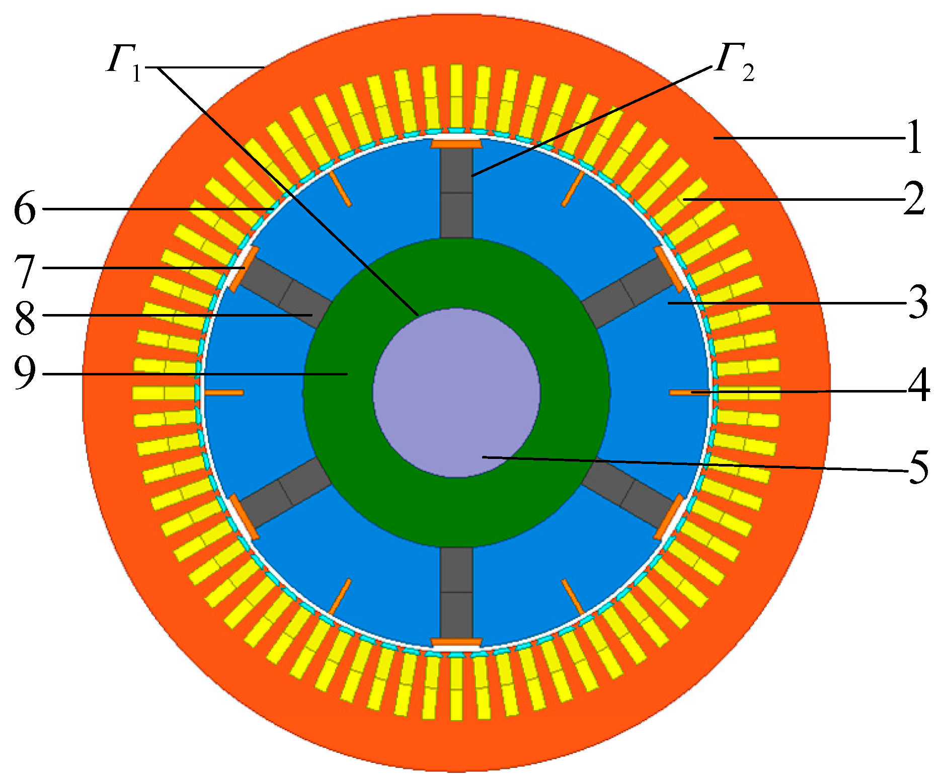
2. Electromagnetic Field Calculation
- (1)
- The influence of the displacement current and the skin effect in the stator windings are ignored.
- (2)
- Materials are isotropic.
- (3)
- The effects of temperature on the conductivity and permeability of the material are ignored, and the properties of materials are considered those at the assumed working temperature.
3. Fluid-Thermal Analysis
3.1. Assumed Conditions
- (1)
- The effects of the cooling medium buoyancy and gravity on the fluid flow are ignored.
- (2)
- The flow rate of the medium in the cooling system is much less than that of the sound velocity, so the fluid is treated as an incompressible fluid.
- (3)
- The steady equilibrium state of the fluid and heat transfer in the cooling system is studied, the mathematical model is aimed at the steady flow of the fluid, and the quantity of the equation does not change with time.
- (4)
- The given fluid mass flow rated is chosen as let boundary.
- (5)
- The given fluid pressure is selected as the outlet boundary conditions.
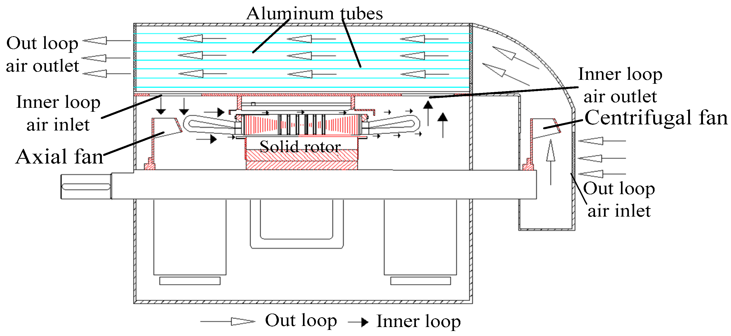
3.2. Modeling of Flued Thermal Coupling Analyses
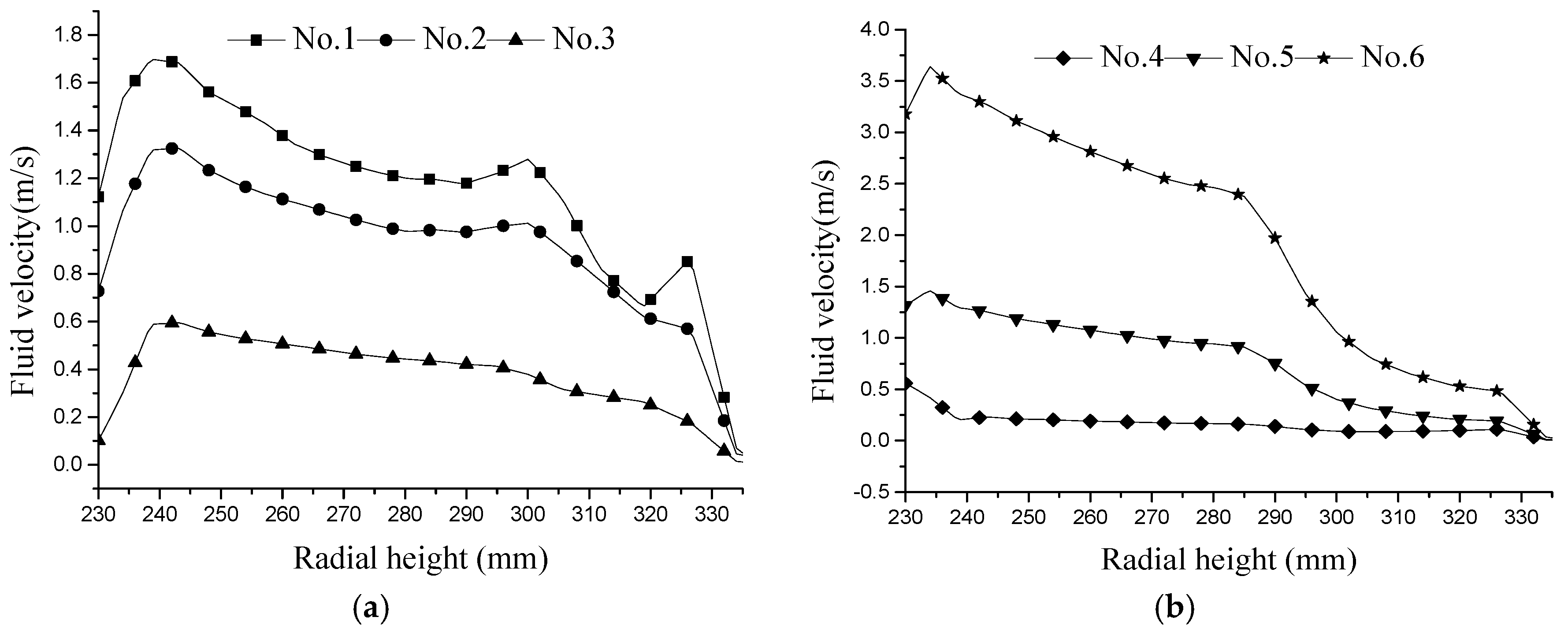
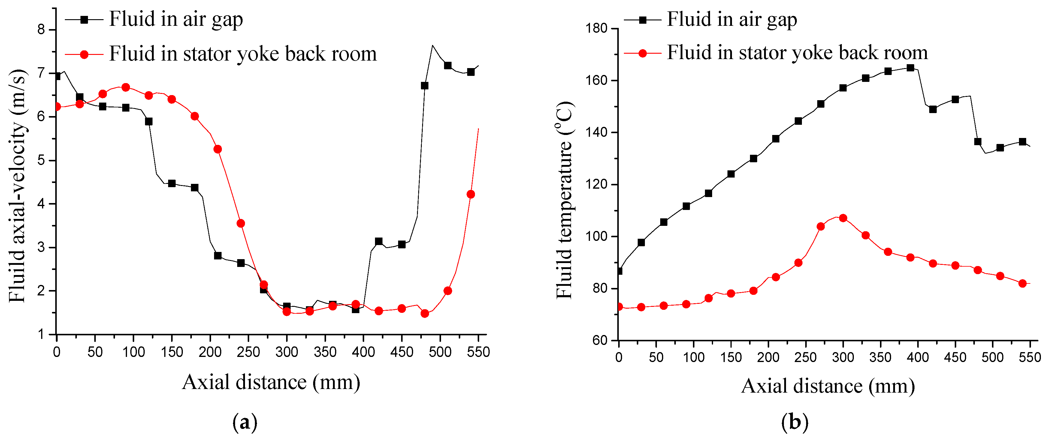
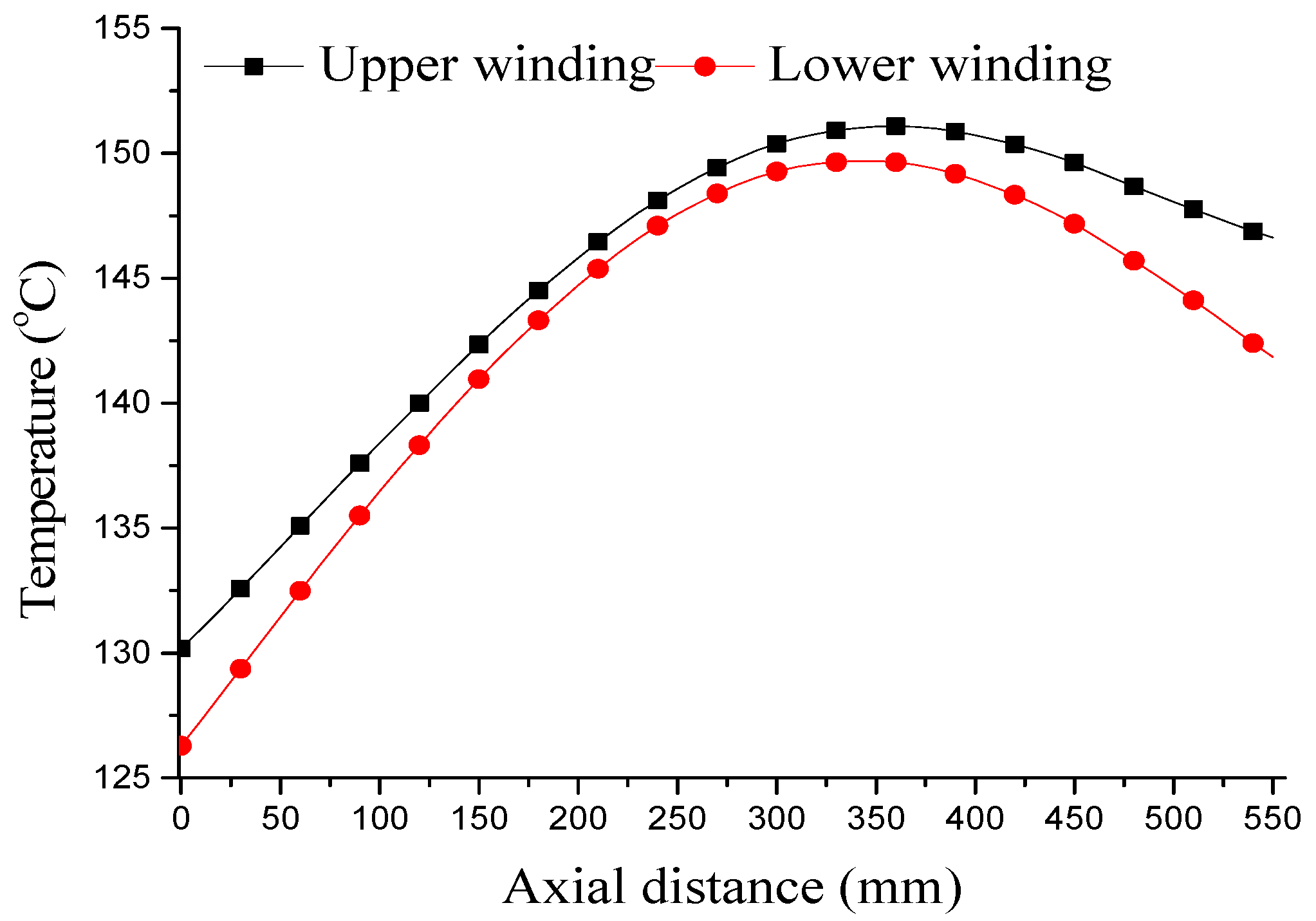
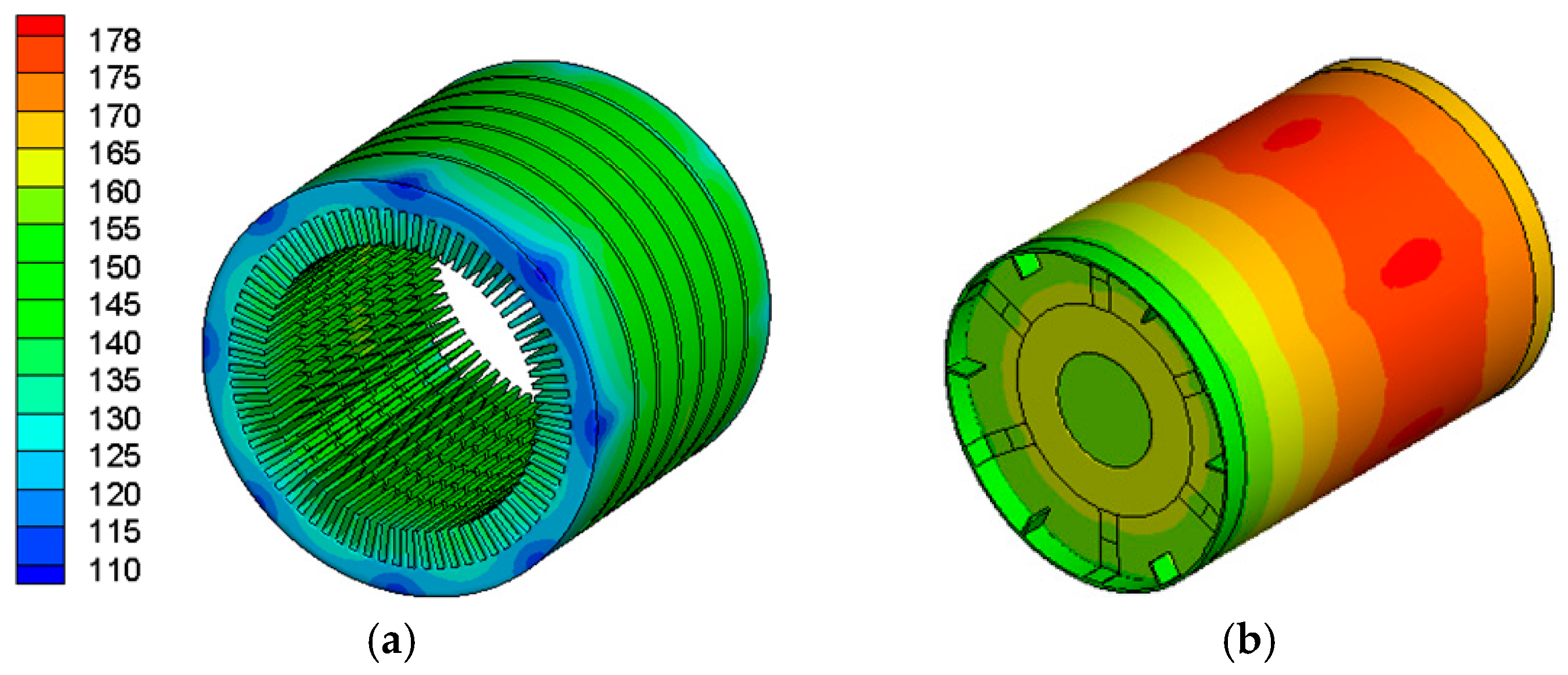
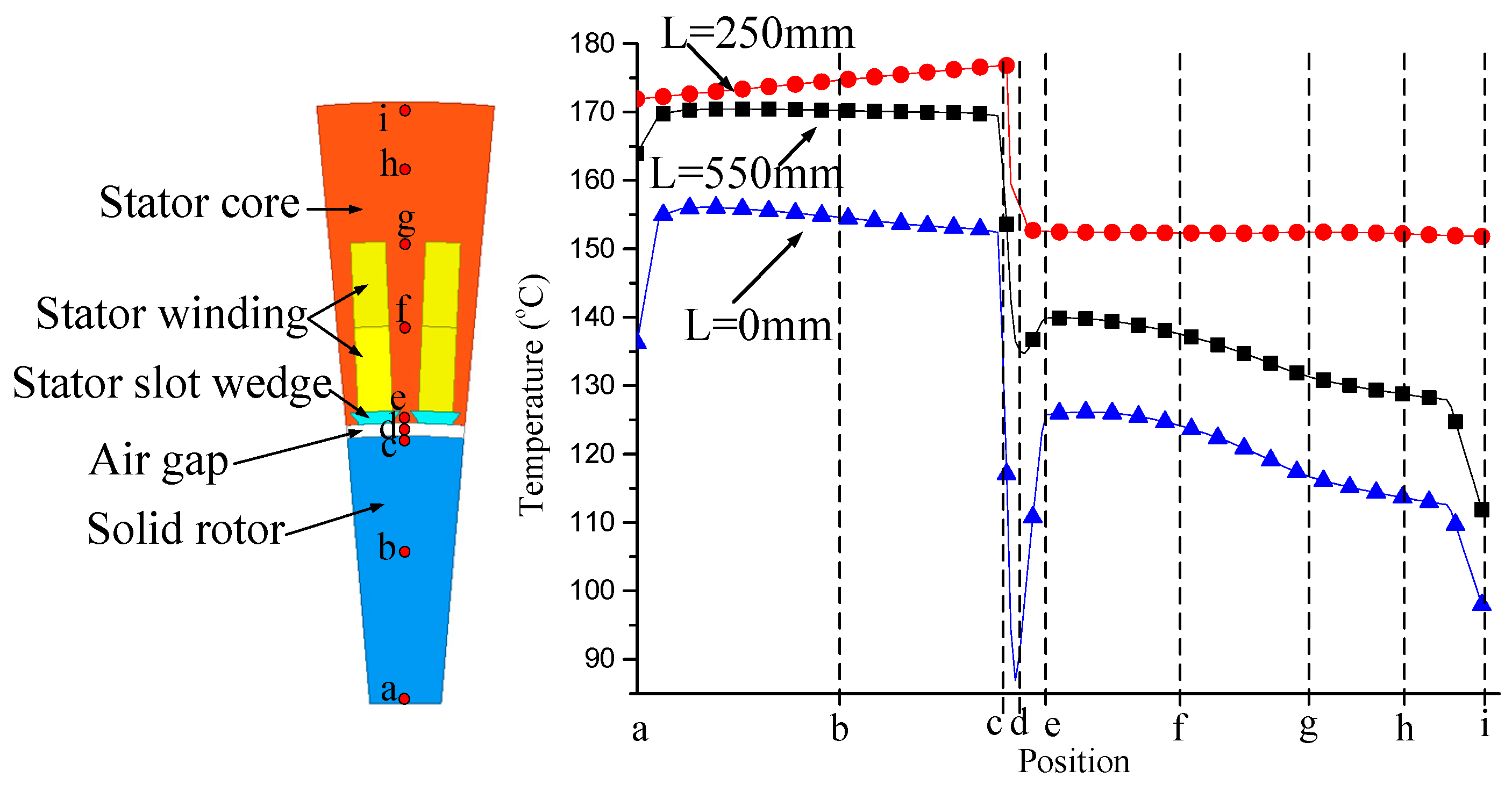
3.3. Temperature in LSPMSM with Solid Starting Cage Bar
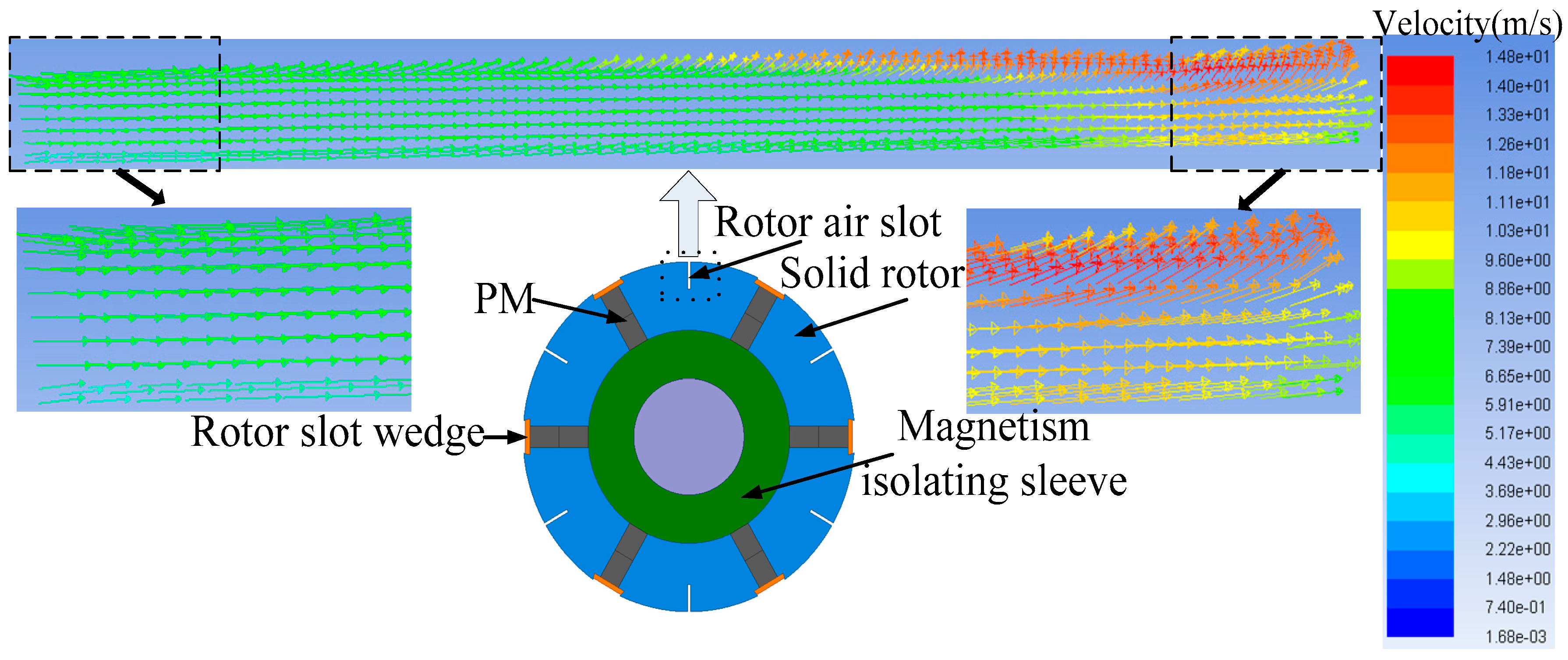
3.4. Temperature in LSPMSM with Rotor Air Slot
4. Conclusions
- (1)
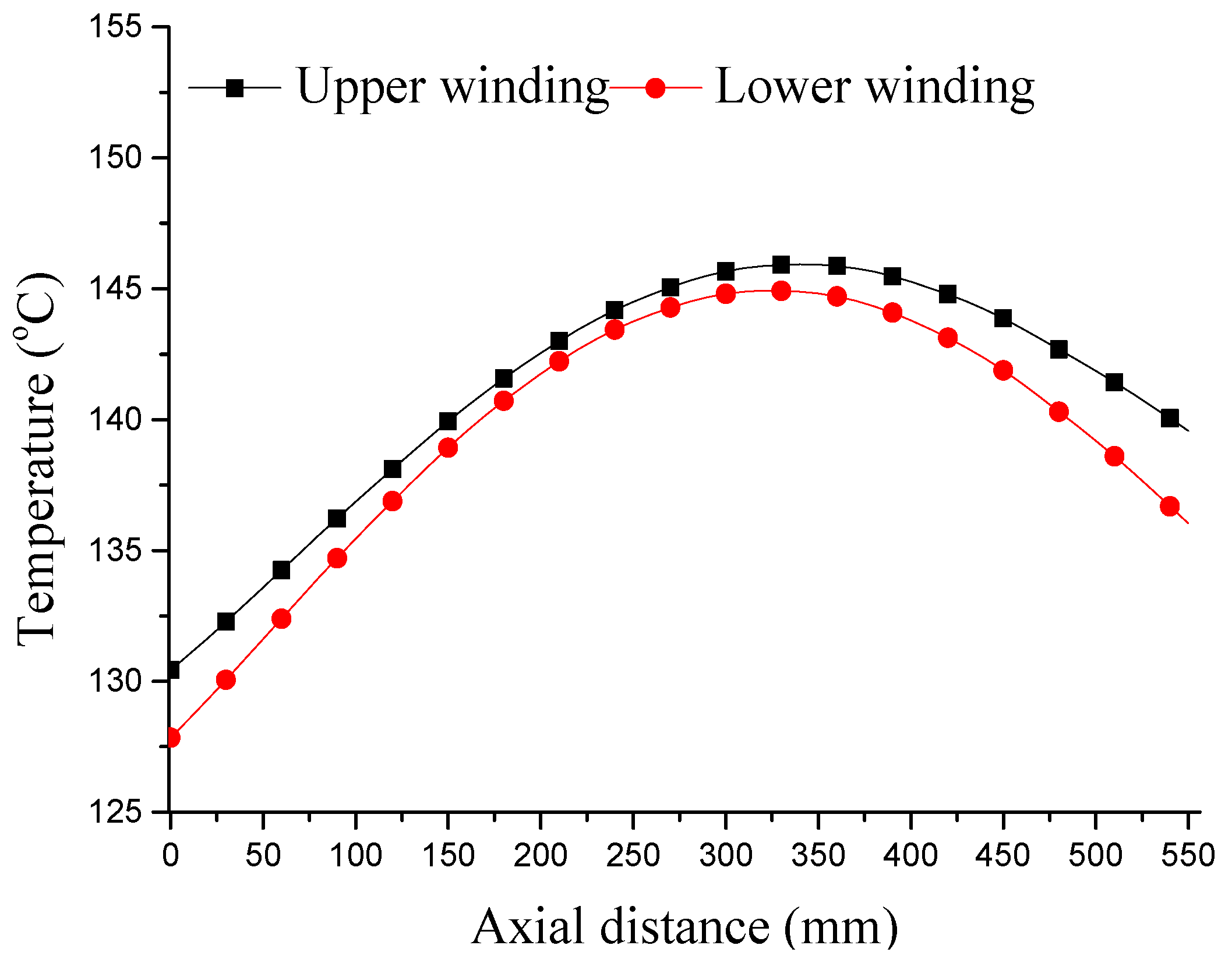
- The temperatures in the LSPMSM with solid starting cage bars rise observably along the axial direction. The permanent magnet may be demagnetized due to operating at high temperature for a long time. The axial temperature difference would cause unbalanced thermal stress that cannot be ignored.
- (2)
- The proposed rotor air slot cooling structure could make the cooling medium more effective in heat transmission and promote the highest temperature and the axial temperature difference reduces obvious, thus making the temperature more evenly distributed in the machine.
- (3)
- The highest temperature of the rotor core and permanent magnet dropped 14.6 °C and 14.9 °C, respectively, and the axial temperature difference gradually decreases in LSPMSM with the proposed rotor air slot structure. This could enhance the temperature distribution in the LSPMSM, and also could provide a reference for cooling system design in electric machines.
Acknowledgments
Author Contributions
Conflicts of Interest
References
- Kurihara, K.; Rahman, M.A. High-efficiency line-start interior permanent-magnet synchronous motors. IEEE Trans. Ind. Appl. 2004, 40, 789–796. [Google Scholar] [CrossRef]
- Lee, J.; Lee, H.W. The performance prediction of controlled-PM LSM in various design schemes by FEM. IEEE Trans. Magn. 2000, 36, 1902–1905. [Google Scholar] [CrossRef]
- In-Soung, J.; Jin, H.; Dong, S.H. 3-D analysis of permanent magnet linear synchronous motor with magnet arrangement using equivalent magnetic circuit network method. IEEE Trans. Magn. 1999, 35, 3736–3738. [Google Scholar] [CrossRef]
- Guo, Y.; Zhu, J.G.; Wu, W. Thermal analysis of SMC motors using a hybrid model with distributed heat sources. IEEE Trans. Magn. 2005, 41, 412124–412128. [Google Scholar] [CrossRef]
- Huang, Y.; Zhu, J.G.; Guo, Y. Thermal analysis of high-speed SMC motor based on thermal network and 3-D FEA with rotational core loss included. IEEE Trans. Magn. 2009, 45, 4684–4687. [Google Scholar] [CrossRef]
- Marignetti, F. Design of axial flux PM synchronous machines through 3-D coupled electromagnetic thermal and fluid-dynamical finite-element analysis. IEEE Trans. Ind. Electron. 2008, 55, 3591–3601. [Google Scholar] [CrossRef]
- Rahman, M.A.; Osheiba, A.M.; Kurihara, K. Advances on single-phase line-start high efficiency interior permanent magnet Motors. IEEE Trans. Ind. Electron. 2012, 59, 1333–1345. [Google Scholar] [CrossRef]
- Knight, A.M.; Mcclay, C.I. The design of high-efficiency line-start motors. IEEE Trans. Ind. Appl. 2000, 36, 1555–1562. [Google Scholar] [CrossRef]
- Bracikowski, N.; Hecquet, M.; Brochet, P.; Shirinskii, S.V. Multiphysics modeling of a permanent magnet synchronous machine by using lumped models. IEEE Trans. Ind. Electron. 2012, 59, 2426–2437. [Google Scholar] [CrossRef]
- Hosoi, T.; Watanabe, H.; Shima, K.; Fukami, T.; Hanaoka, R.; Takata, S. Demagnetization analysis of additional permanent magnets in salient-pole synchronous machines with damper bars under sudden short circuits. IEEE Trans. Ind. Electron. 2012, 59, 2448–2456. [Google Scholar] [CrossRef]
- Nima, F.E.; Mojtaba, M.; Aliakbar, D.A. Line-start permanent magnet motors: Proper design for pole-changing starting method. IET Electr. Power Appl. 2013, 7, 470–476. [Google Scholar] [CrossRef]
- Arumugam, P.; Xu, Z.; La Rocca, A.; Vakil, G.; Dickinson, M.; Amankwah, E.; Hamiti, T.; Bozhko, S.; Gerada, C.; Pickering, S.J. High-Speed Solid Rotor Permanent Magnet Machines: Concept and Design. IEEE Trans. Electrification 2016, 2, 391–400. [Google Scholar] [CrossRef]
- Mahmoudi, A.; Kahourzade, S.; Rahim, N.A.; Hew, W.P.; Uddin, M.N. Design, analysis, and prototyping of a novel-structured solid-rotor-ringed line-start axial-flux permanent-magnet motor. IEEE Trans. Ind. Electron. 2014, 61, 1722–1734. [Google Scholar] [CrossRef]
- Li, W.; Zhang, X.; Cheng, S. Study of solid rotor line-start PMSM operating. In Proceedings of the International Conference on Electrical Machines, Wuhan, China, 17–20 October 2008; pp. 1803–1809. [Google Scholar]
- Akiror, J.C.; Rahman, T.; Pillay, P. Progress on formulas for core loss calculations. In Proceedings of the 20th International Conference on Electrical Machines, Marseille, France, 2–5 September 2012; pp. 1803–1809. [Google Scholar]
- Debruyne, C.; Polikarpova, M. Evaluation of the efficiency of line-start permanent-magnet machines as a function of the operating temperature. IEEE Trans. Ind. Electron. 2014, 61, 4443–4454. [Google Scholar] [CrossRef] [Green Version]
- Weili, L.; Hongbo, Q. Influence of copper plating on electromagnetic and temperature fields in a high-speed permanent-magnet generator. IEEE Trans. Magn. 2012, 48, 2247–2253. [Google Scholar] [CrossRef]
- Weili, L.; Xiaochen, Z.; Shukang, C.; Junci, C. Thermal optimization for a HSPMG used for distributed generation systems. IEEE Trans. Ind. Electron. 2013, 60, 474–483. [Google Scholar] [CrossRef]
- De Donato, G.; Capponi, F.G.; Caricchi, F. No-load performance of axial flux permanent magnet machines mounting magnetic wedges. IEEE Trans. Ind. Electron. 2012, 59, 3768–3779. [Google Scholar] [CrossRef]
- Aliabad, A.D.M.; Mirsalim, N.; Ershad, F. Line-start permanent-magnet motors: Significant improvements in starting torque, synchronization, and steady-state performance. IEEE Trans. Magn. 2010, 46, 4066–4072. [Google Scholar] [CrossRef]
- Aubry, J.; Ahmed, H.B.; Multon, B. Sizing Optimization methodology of a surface permanent magnet machine-converter system over a torque-speed operating profile: Application to a wave energy converter. IEEE Trans. Ind. Electron. 2012, 59, 2116–2125. [Google Scholar] [CrossRef]
- Kano, Y.; Kosaka, T.; Matsui, N. A simple nonlinear magnetic analysis for axial-flux permanent-magnet machines. IEEE Trans. Ind. Electron. 2010, 57, 2124–2133. [Google Scholar] [CrossRef]
- Hsieh, M.F.; Hsu, Y.C.; Dorrell, D.G. Design of large-power surface-mounted permanent-magnet motors using postassembly magnetization. IEEE Trans. Ind. Electron. 2010, 57, 3376–3384. [Google Scholar] [CrossRef]


| Symbol | Quantity | Values and Unit |
|---|---|---|
| PN | Rated Power | 315 kW |
| UN | Rated Voltage | 6000 V |
| D1 | Outside diameter of stator | 670 mm |
| Di1 | Inner diameter of stator | 460 mm |
| P | Poles | 6 |
| f | Frequency | 50 Hz |
| Air gap | 4.2 mm | |
| L | Core length | 550 mm |
| nk | Number of stator radial ventilation ducts | 6 |
| bk | Stator radial ventilation duct width | 10 mm |
| Copper Loss | Iron Loss | Friction Loss | Eddy Current Loss | |||
|---|---|---|---|---|---|---|
| Solid Rotor | Rotor Slot Wedge | Solid Starting Cage Bar | Permanent Magnet | |||
| 4389 | 5412 | 6866 | 2724 | 454 | 83 | 45 |
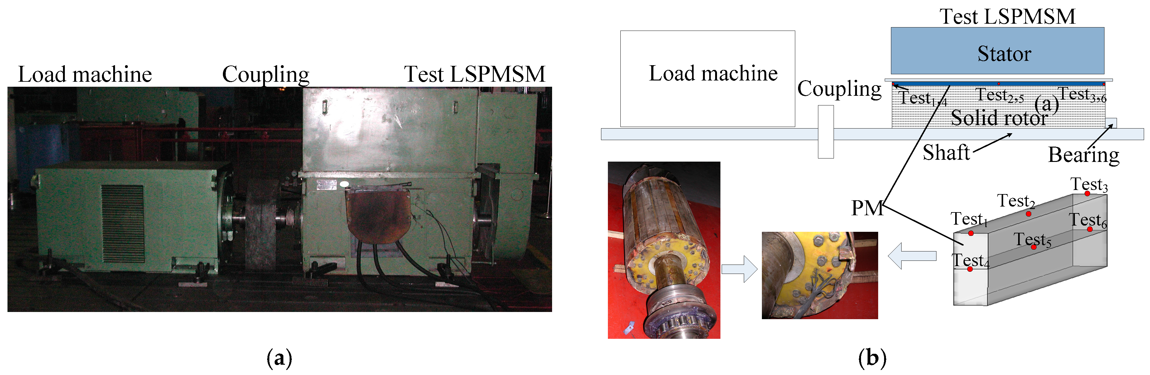
| Measuring Point | Measured Value | Calculated Value |
|---|---|---|
| Test1 | 144.7 | 150 |
| Test2 | 181.4 | 176 |
| Test3 | 176.7 | 171 |
| Test4 | 142.7 | 154 |
| Test5 | 168.7 | 169 |
| Test6 | 169.5 | 170 |
| Temperature | Highest Temperature(°C) | ||
|---|---|---|---|
| Component | Rotor with Solid Rotor Cage Bar | Rotor with Air Slot | |
| Stator core | 152 | 152 | |
| Stator windings | 150.9 | 150 | |
| Rotor core | 178.6 | 164 | |
| PM | 178.9 | 164 | |
© 2017 by the authors. Licensee MDPI, Basel, Switzerland. This article is an open access article distributed under the terms and conditions of the Creative Commons Attribution (CC BY) license (http://creativecommons.org/licenses/by/4.0/).
Share and Cite
Cao, Z.; Li, W.; Li, J.; Zhang, X.; Li, D.; Zhang, M. Research on the Temperature Field of High-Voltage High Power Line Start Permanent Magnet Synchronous Machines with Different Rotor Cage Structure. Energies 2017, 10, 1829. https://doi.org/10.3390/en10111829
Cao Z, Li W, Li J, Zhang X, Li D, Zhang M. Research on the Temperature Field of High-Voltage High Power Line Start Permanent Magnet Synchronous Machines with Different Rotor Cage Structure. Energies. 2017; 10(11):1829. https://doi.org/10.3390/en10111829
Chicago/Turabian StyleCao, Zhaobin, Weili Li, Jinyang Li, Xiaochen Zhang, Dong Li, and Meiwei Zhang. 2017. "Research on the Temperature Field of High-Voltage High Power Line Start Permanent Magnet Synchronous Machines with Different Rotor Cage Structure" Energies 10, no. 11: 1829. https://doi.org/10.3390/en10111829