Minimization of the Electromagnetic Torque Ripple Caused by the Coils Inter-Turn Short Circuit Fault in Dual-Redundancy Permanent Magnet Synchronous Motors

Key Laboratory of Smart Grid of Ministry of Education, Tianjin University, Tianjin 300072, China
*
Author to whom correspondence should be addressed.
Energies 2017, 10(11), 1798; https://doi.org/10.3390/en10111798
Submission received: 27 September 2017
/
Revised: 3 November 2017
/
Accepted: 5 November 2017
/
Published: 8 November 2017
Abstract
:With the development of electric vehicles and More-Electric/All-Electric aircraft, high reliability is required in motor servo systems. The redundancy technique is one of the most effective methods to improve the reliability of motor servo systems. In this paper, the structure of dual-redundancy permanent magnet synchronous motor (DRPMSM) with weak thermal coupling and no electromagnetic coupling is analyzed and the mathematical model of this motor is established. However, there is little research on how to suppress the torque ripple caused by short-circuited coils in the DRPMSM. The main contribution of this paper is to present the advantages of DRPMSM and to find a way to suppress the torque ripple caused by the short circuit fault in DRPMSM. In order to improve operation quality and enhance the reliability of DRPMSM after a short circuit occurs, the torque ripple caused by the coils inter-turn short circuit fault in DRPMSM is analyzed in detail. Then, a control method for suppressing the electromagnetic torque ripple of a short-circuited coil is proposed for the first time by using an improved adaptive proportional resonant (PR) controller and a proportional integral (PI) controller in parallel. PR control is a method of controlling alternating components without steady-state error, and it can be used to suppress torque ripple. DRPMSM adopts speed and current double closed-loop control strategies. An improved adaptive PR controller and a PI controller are employed in parallel for the speed loop, while traditional PI control is adopted in current loop. From the simulation and experimental results, the torque ripple is reduced from 45.4 to 5.6% when the torque ripple suppression strategy proposed in this paper is adopted, in the case that the speed is 600 r/min. The torque ripple suppression strategy based on the PR controller can quickly and effectively suppress the torque ripple caused by the short-circuited coils, which makes the motor speed more stable.
1. Introduction
Environmental pollution and energy shortages have become more and more serious problems. In many places, electrical power has successfully replaced the traditional energy sources. The motor, as an important device which transfers the electrical energy into the mechanical energy, is widely employed in many fields such as aerospace, electric vehicles and military applications. Specifically, permanent magnet motors, which can achieve high torque and power density, will replace other traditional motors. The permanent magnet synchronous motor (PMSM) has a lot of advantages such as high power density, high operation efficiency, simple structure and simple control, and it has been widely used in various fields [1,2,3,4,5]. Consequently, the permanent magnet synchronous motor has drawn more and more attention and recognition.
With the development of the electric vehicle and the More-Electric/All-Electric aircraft technique, higher reliability of PMSM servo systems is required. The electrical and mechanical actuator is a kind of servo system, and it is an important component of both aircraft and electric vehicles. The redundancy technique is one of the most effective methods to improve the reliability of the PMSM servo system by adding extra resources [6]. Especially, in the case of high reliability, dual-redundancy permanent magnet synchronous motors (DRPMSMs) will play an important role [7,8]. Generally, the structure of DRPMSMs can be classified into two categories, that is, series structure and parallel structure [9,10,11,12,13,14,15,16,17,18,19]. In the series structure of the dual-redundancy motor, two motors are coaxially connected [9,10,11,12]. However, in the parallel structure of the dual-redundancy motor, the stator has two sets of three-phase windings and shares one permanent magnet rotor [13,14,15,16,17,18,19,20,21]. The series structure of the dual-redundancy motor obviously does not have the electromagnetic and thermal coupling between the two sets of windings, but it leads to a large volume, torque dispute and other shortcomings [10]. Thus, in comparison, the parallel structure of the DRPMSM has more advantages. In the past few years, dual-redundancy motors with a parallel structure have been presented in many papers. In [14,15,16,17,18], the parallel structures of the dual-redundancy motor consist of two sets of independent windings with 30 electrical degree shifts in space, and a mutual rotor. The mutual inductance between two sets of three-phase windings is large as they are alternately embedded in stator slots. In [19], the principle of the decoupling through two different winding connections (distributed and concentrated) for the double-star winding permanent magnet motor is presented. In [20], the structure of the dual-redundancy motor is comprised of one set of windings embedded in half of the circle of stator and the other set embedded in the other half of that, and two sets of independent windings have zero electrical degree shifts in space. This structure has reduced the mutual inductance between two sets of windings compared with the previous structure of dual-redundancy motors. In [21], the insertion of an additional tooth with a particular geometry reduces the magnetic coupling between the two adjacent layers and consequently reduces the coupling of the two channels significantly. However, the inductance matrix of dual-redundancy motors is not a diagonal matrix. Thus there is no complete decoupling between the two degrees of redundancy. There are still mutual inductances between the two sets of windings of the parallel structure of the DRPMSMs, which means there is electromagnetic coupling. When a set of three-phase windings faces a dangerous short circuit fault, the other set of normal three-phase windings will also be affected by short-circuited coils from electromagnetism. To address this problem, the DRPMSM with weak thermal coupling and no electromagnetic coupling is proposed in this paper [22]. There is no electromagnetic coupling between two sets of windings in this type of DRPMSM.
Under normal conditions, two sets of three-phase windings of the DRPMSM with weak thermal coupling and no electromagnetic coupling operate at the same time, in a dual-redundancy operation mode. When a fault occurs in one set of three-phase windings, the power supply of this set of windings is cut off, and the other set of three-phase windings continues to supply power. In single-redundancy operation mode, in which the other set of three-phase windings still works, the reliability of the motor is effectively improved. The main faults of motors are winding open circuit fault and winding short circuit fault [23,24]. When the winding open circuit fault occurs, it has no adverse effect on the normal windings. When the motor is operating in single-redundancy operation mode due to a short circuit fault, the fault windings will not have an impact on the normal winding due to the electromagnetic power. But the interaction between the current of short-circuited coils and permanent magnetic field not only produces a brake electromagnetic torque corresponding to the copper loss of short-circuited coils, but also produces an alternating electromagnetic torque with a doubled supply power frequency. The alternating electromagnetic torque affects the closed-loop speed controller, which will lead to the fluctuation of speed and increase vibration noise [25,26,27]. There is little research on how to suppress the torque ripple caused by short-circuited coils in the DRPMSM.
This paper analyzes the inter-turn short circuit fault of the DRPMSM with weak thermal coupling and no electromagnetic coupling. The novelties of the DRPMSM with weak thermal coupling and no electromagnetic coupling include two aspects. The first aspect is that the DRPMSM adopts 12 slots, and 10 poles, which can eliminate the electromagnetic coupling between phases. In other words, the mutual inductance of each phase is almost zero. The second aspect involves placing the small teeth at the center of the slot, in which the coils on two sides of the small teeth are in different phases. The insulating plates are placed on two sides of the small teeth so that the phases have weak thermal coupling. The inter-turn short circuit fault of the DRPMSM may cause the output torque of the motor to fluctuate. The torque pulsation of the DRPMSM can generate abnormal vibration and unwanted speed fluctuation. Therefore, reducing the torque pulsation is essential to improve the torque performance of the DRPMSM drive system in single-redundancy operation mode. In order to overcome the torque ripple caused by the current of short-circuited coils and improve the performance of the single-redundancy operation of the DRPMSM, this paper firstly proposes an electromagnetic torque ripple suppression strategy for the DRPMSM, based on the proportional resonant (PR) controller [28,29]. When a coils short circuit fault occurs and the DRPMSM shifts into single-redundancy operation mode, the PR controller is paralleled with the proportional integral (PI) controller in the speed loop to suppress the electromagnetic torque ripple output. As an inter-turn short circuit fault of the DRPMSM may occur at various speeds, a frequency adaptive PR controller is adopted in this paper. The simulation and experimental results show that the ripple of the motor output electromagnetic torque caused by short-circuited coils is effectively suppressed, and the motor speed becomes more stable.
2. The Structure of the Novel DRPMSM
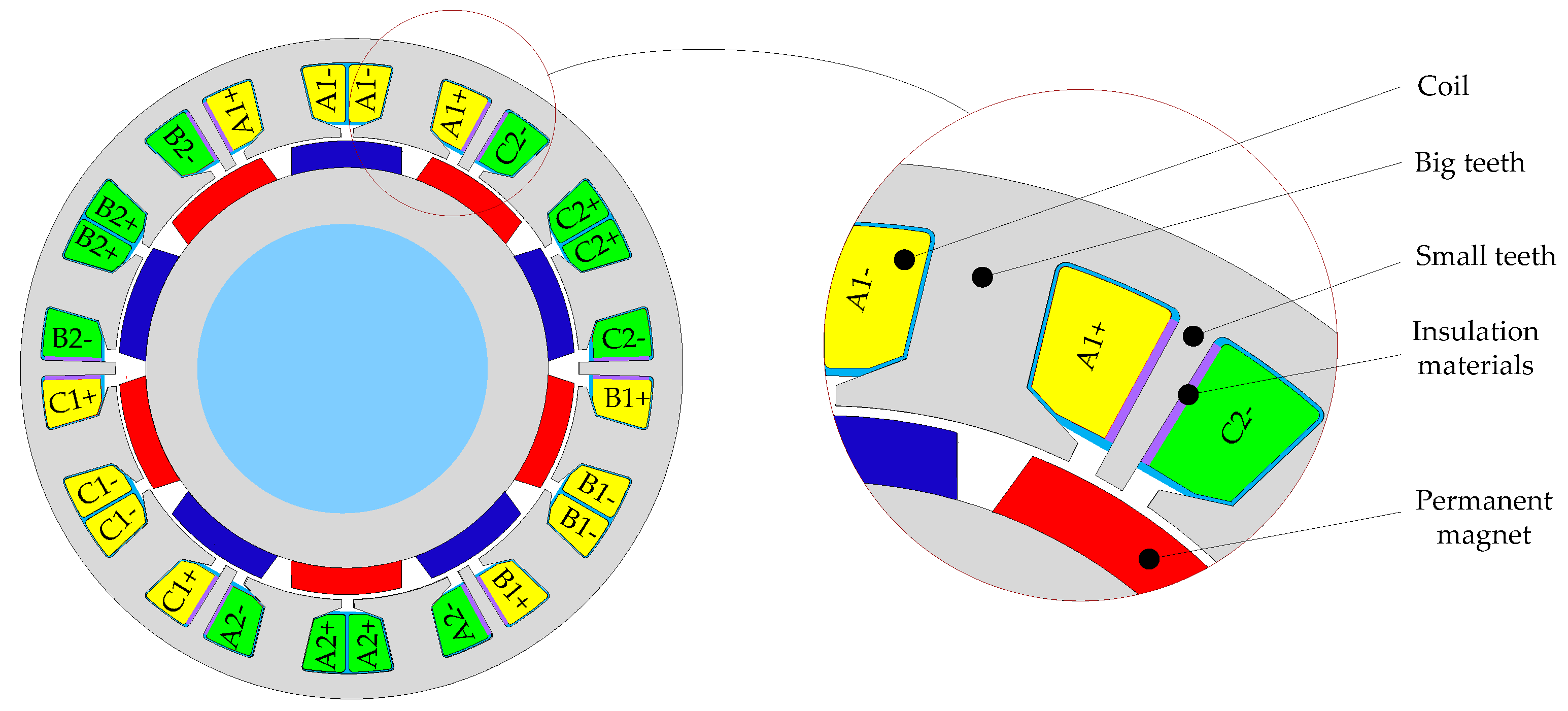
The cross-section of the DRPMSM with weak thermal coupling and no electromagnetic coupling and its stator windings outspread are shown in Figure 1 and Figure 2 respectively.
The DRPMSM with weak thermal coupling and no electromagnetic coupling is evolved from the traditional 12 slot, 10 pole permanent magnet synchronous motor with fractional slot concentrated winding [30]. The small teeth are placed at the center of the slot, in which the coils on two sides of the small teeth are in different phase. Since the slot leakage flux of coils closes from the small teeth, the two adjacent phase windings have almost no electromagnetic coupling. The mutual inductance between the windings is almost zero, thus electromagnetic coupling is eliminated. The insulating plates are placed on two sides of the small teeth so that the phases have weak thermal coupling. The permanent magnet rotor uses non-equal thickness and tile-shaped permanent magnet which is parallel magnetized. The stator is arranged with six-phase windings of A1, B2, C1, A2, B1 and C2. Each phase winding consists of a set of coils in forward series connection and a set of coils in subtractive series connection. The series law of the two coils in the three-phase windings of A1, B1 and C1 is opposite to that of the two coils in the three-phase windings of A2, B2 and C2. The electromotive force of six-phase windings is equal, and the phase difference is 120 electrical angle. The resistance and inductance of each phase are the same respectively, and the mutual inductance between any two phases is zero. The winding axis of A1, B1 and C1 phase coincides with the winding axis of A2, B2 and C2. If X1, Y1 and Z1, X2, Y2 and Z2 are connected to form two star points, two independent three-phase star-connected windings A1B1C1 and A2B2C2 will be formed. The two sets of three-phase symmetrical windings intersect with each other in space. If X1, Y2 and Z1, X2, Y1 and Z2 are connected to form two star points, two independent three-phase symmetrical windings A1B2C1, and A2B1C2 will be formed. Two sets of three-phase windings are arranged continuously. The motor performance of the cross-arranged windings is better by comprehensive comparison.
In order to prove that there is no mutual inductance in the DRPMSM adopted in this paper, the finite element model of the DRPMSM is established using Ansoft 15.0 software. The structural parameters of the DRPMSM are shown in Table 1, and the inductance matrix of the DRPMSM is obtained by the static magnetic field simulation in Table 2.
Table 2 shows that the mutual inductance between phases is smaller than the phase winding inductance by at least two orders of magnitude, and thus the mutual inductance can be ignored. It is verified that the mutual inductance between the phase windings of the motor is almost zero, and the two sets of windings are independent with each other in the electrical and electromagnetic aspects.
The drive system topology of the DRPMSM is shown in Figure 3. Two sets of three-phase symmetrical windings are fed by two inverters. The number of power supplies can be one or two.
Under normal conditions, the dual-redundancy motor operates in dual-redundancy mode. When a fault occurs, the dual-redundancy motor operates in single-redundancy operation mode.
3. The Mathematical Model of the DRPMSM
The phase axes of two sets of three-phase windings coincide with each other in the DRPMSM with weak thermal coupling and no electromagnetic coupling. Therefore, there is no mutual inductance between any two phases of one set of three-phase winding, and there is no mutual inductance between the two sets of windings, either. In order to establish the mathematical model of the motor, the assumptions should be made as follows:
- The influence of the saturation of the magnetic circuit is ignored;
- The stator magnetic field is sinusoidal ignoring the saturation of the magnetic circuit and the higher harmonics;
- The sine wave electromotive force is induced in the phase windings;
- The eddy current and hysteresis loss are ignored.
The voltage equation and flux linkage equation can be expressed as follows:
where
u, i, ψ, and ψM are the column matrices of the phase voltage, phase current, total flux linkage and permanent magnet flux linkage of two sets of three-phase windings respectively, and the units are V, A and Wb respectively. R and L represent the resistance and inductance of each phase windings, and the units are Ω and H; θe is the electrical angle of the rotor position angle, and the unit is rad. The direct axis (d axis) of the permanent magnet rotor coincides with the positive axis of the stator A1 and A2 windings, which is taken as the initial position. ψPMm is the maximum value of the permanent magnet flux linkage for phase windings, and the unit is Wb.
where Nc is the number of turns per coil; ky1 is the fundamental pitch-shortening factor of the coils; kq1 is the fundamental distribution factor of the phase windings; φm is the fundamental magnetic flux per pole, and the unit is Wb.
When the DRPMSM works in dual-redundancy operation mode, the permanent magnet back electromotive force (EMF) of each phase windings can be expressed as follows:
where ωe is the instantaneous electrical angular velocity of the permanent magnet rotor, and the unit is rad/s. ωe can be expressed as follows:
The two sets of three-phase symmetrical windings are fed by three symmetrical currents respectively, and the electromagnetic torque formed by the interaction of the stator current and the permanent magnetic field of the rotor is expressed as follows:
where Te is the electromagnetic torque with the unit N·m; Pe is the electromagnetic power with the unit W; ω is the rotor mechanical angular velocity with the unit rad/s; and p0 is the pole pairs of permanent magnet on the rotor of motor.
Under the condition of constant power, the physical quantities of the two sets of three-phase windings are transformed from the three-phase stationary coordinate system to the dq synchronous rotating coordinate system. The voltage equation and the flux equation of the dq synchronous rotating coordinate system are given by:
where
Electromagnetic torque of the DRPMSM with weak thermal coupling and no electromagnetic coupling is given by:
where KT is the electromagnetic torque coefficient, and the unit is N·m/A.
The motion equation of the motor is given by:
where J is the equivalent moment of inertia of the motor drive system, and the unit is kg·m2; B is the damping coefficient, and the unit is N·m/s; TL is the load torque, and unit is N·m. It can be seen from Equation (17) that the electromagnetic torque of the DRPMSM is provided by two sets of windings. When one of the windings is removed due to windings fault, the other set of windings can still provide torque.
4. Analysis of Short Circuit Fault of DRPMSM
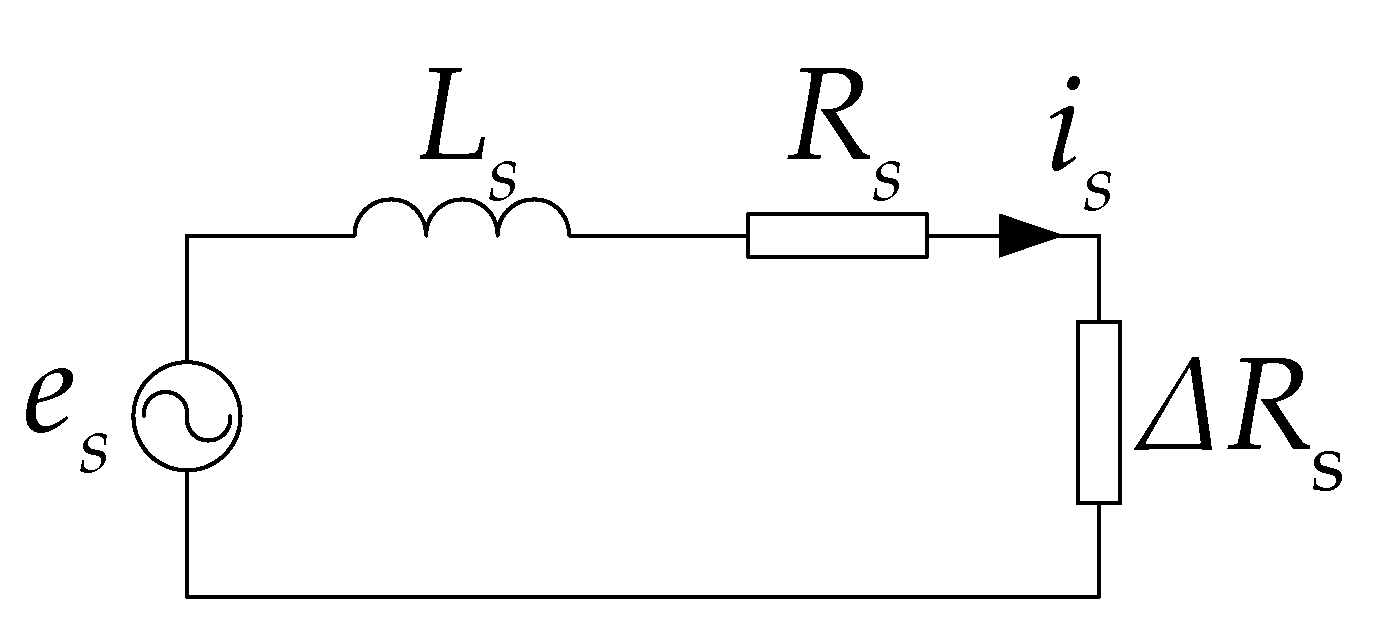
If coils of a phase are partially shorted in the DRPMSM with weak thermal coupling and no electromagnetic coupling, the three-phase windings with the short-circuit windings can be removed. Only the normal three-phase windings work in single-redundancy operation mode. The equivalent circuit of short circuit fault coils is shown in Figure 4 according to the generator convention, where es represents the permanent magnet induction EMF in the short circuit fault coils; is represents the current in the short circuit fault coils; Ls represents the inductance of the short circuit fault coils; Rs represents the resistance of the short circuit fault coils; ΔRs represents the contact resistance at the short circuit.
If the initial phase is not considered, it is assumed that the electromotive force induced by the permanent magnet in the local short circuit is expressed as follows:
where Ns is the number of shorted turns of the coil; φ0 is the initial phase angle.
The short-circuit current in the local short circuit is expressed as follows:
where
Electromagnetic torque generated by the short-circuit current is given by:
It can be seen from Equation (24) that the electromagnetic torque generated by the short-circuit current has two parts. The first term is the stationary component Ts-. Ts- consumes the active power which is the copper loss on the resistance of the local short-circuited coils. The second term is an alternating component, denoted as a short-circuit torque ripple Ts~. The stationary component can be compensated by increasing the electromagnetic torque generated by the normal set of three-phase windings, while the short-circuit torque ripple Ts~ brings the second harmonic component to the motor output electromagnetic torque. If no suppression strategy is taken, the motor speed will fluctuate significantly.
Normally viscosity coefficient B is very small and can be neglected. Using differentiator (s) instead of (d/dt) from (19), the plant transfer function between the motor speed and the torque is:
It can be seen that the speed would oscillate at the same harmonic frequencies as those of Ts~, especially at low operating speeds. The amplitude of the ripple speed is inversely proportional to the ripple frequency, and then inversely proportional to the rotor speed.
5. Suppression Strategy of Torque Ripple Caused by Short-Circuited Coils
5.1. The Principle of Suppression of Short Torque Ripple Caused by Short-Circuited Coils
The DRPMSM usually adopts dual-closed loop control strategy, and the speed loop and current loop adopt the PI controller. In the single-redundancy operation mode, the torque ripple generated by short-circuited coils brings the second harmonic component to the actual speed of the DRPMSM. The infinite DC gain of the PI controller can force the DC steady-state error to zero but it cannot suppress the disturbance caused by the short-circuited coils. Because of the limited bandwidth of the speed loop with PI controller, standard integrators can achieve good none-error control at zero frequency, but not at other frequencies. The gain of the PR controller based on the internal model principle at the resonant frequency point is infinite, and thus it can achieve none-error control at resonant frequency. PR controller, a kind of control algorithm, can control alternating components without steady-state error, and it is widely used in inverters, grid connected system and harmonic elimination occasions [31]. In this paper, the PR controller is used to suppress the torque ripple generated by short-circuited coils when the DRPMSM works in single-redundancy operation mode.
In the dual-redundancy operation mode, the speed control system of DRPMSM adopts speed plus current dual-closed loop and vector control strategy of id = 0. The block diagram of the speed and current dual-closed loop control system is shown in Figure 5, and the output of the speed loop is used as the current loop reference value of the two sets of stator windings.
In Figure 5, GACR(s), Ginv(s), Gc(s) and Gcf(s) represent the transfer functions of the current controller, the voltage source inverter, the motor armature loop, and the current filter respectively. They are defined as follows:
where kP1 represents the proportionality factor of the current controller; τi1 represents the integral time constant of the current controller; KT represents the inverter amplification factor; τd represents time constant of space vector pulse width modulation (SVPWM) voltage source inverter considering the switch delay and dead time; τcf represents the time constant of the current filter; and τsample represents the sampling time.
As the sampling time, dead time and the time of current filter have little influence on the system, the inverter is simplified as the first order inertial link. The approximate time constant of the inverter is given by:
In order to avoid the overshoot of the current loop and obtain a good dynamic response, the current PI controller parameters kp1 and τi1 should satisfy the following relationships:
When the PI parameter is selected by Equations (32) and (33), the closed loop transfer function of the current loop is equivalent to the first order inertial link.
where τc is the equivalent time constant.
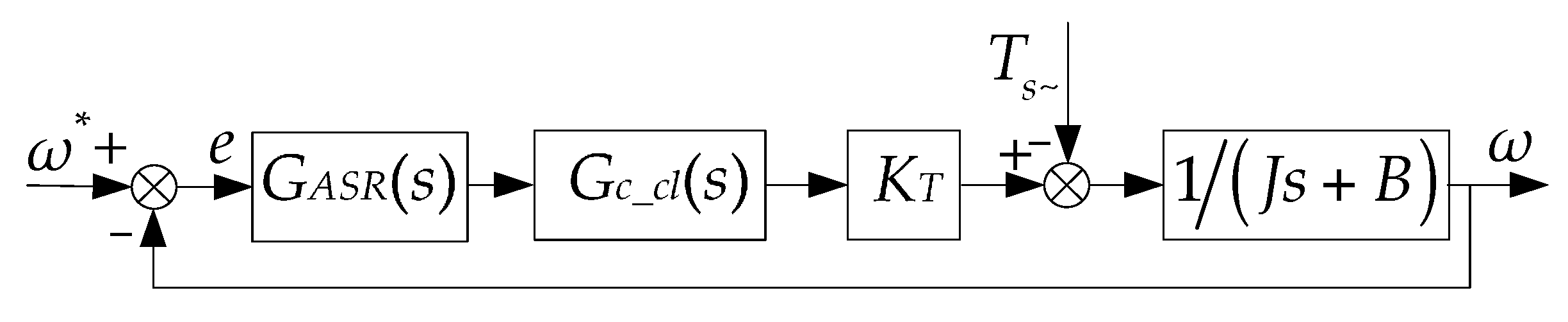
When the system encounters a short circuit fault, the faulty windings are removed and the DRPMSM is operating in single-redundancy operation mode. The torque ripple caused by the short-circuited coils is used as the torque interference of the system. The transfer function of the DRPMSM in single-redundancy operation mode is shown in Figure 6.
In Figure 6, GASR(s) represents the transfer function of the speed controller:
where kp2 represents the proportionality factor of the speed controller; τi2 represents the integral time constant of the speed controller.
As shown in Figure 7, Ts~ is the torque ripple generated by short-circuited coils. It can be seen from the previous analysis that the pulsation frequency of the torque ripple is twice that of the electrical angular velocity of the rotor.
It is assumed that the torque ripple Ts~ is:
where TsM is the amplitude of torque ripple.
Transforming the Equation (35) into complex frequency domain,
The given angular speed ω* is set to zero, and the error e(s) is used as the output, Ts~ as input.
According to the control theory, in order to regulate e(s) to zero, the transfer function of the speed controller must contain 1/(s2 + (2ωe)2) factor. The PR controller satisfies this requirement. When the system reaches the steady state, the PR controller generates sinusoidal oscillation signals with constant frequency and amplitude to suppress the torque ripple caused by short-circuited coils. Therefore, the PR control can restrain the torque ripple [32,33].
5.2. Principle of Frequency Adaptive PR Controller
The ideal PR controller transfer function is given as:
where ω0 is the resonant angular frequency; kr is the resonant coefficient of the resonant controller; and kp is the proportional coefficient. The gain expression of the PR controller at the resonant frequency can be obtained as:
The gain of the PR controller is infinite at the resonant frequency s = jω0. Therefore, the PR controller can achieve none-error control at the resonant frequency.
The gain of the PI controller at the resonant frequency can be obtained as:
The gain of GASR(s) is limited at the resonant frequency s = jω0, but the gain is infinite at the DC operating frequency ω0 = 0. Therefore, the PI controller cannot suppress the torque ripple.
The Bode diagram of the ideal PR controller is shown in Figure 7.
It can be seen from Figure 7 that the gain of the ideal resonant controller is relatively high at the resonant frequency point and drastically declines except for the resonant frequency point. This makes the control system quite sensitive to the parameter change and not stable. Therefore, the improved PR controller is adopted in the paper.
The improved PR controller transfer function is given as:
The improved PR controller’s Bode diagram is also shown in Figure 7. The gain is reduced compared to the ideal PR controller, but it can be increased by adjusting kp. The bandwidth of the controller can be increased and a better control performance can also be achieved by adjusting the ωc even if the ω0 fluctuates in a certain range.
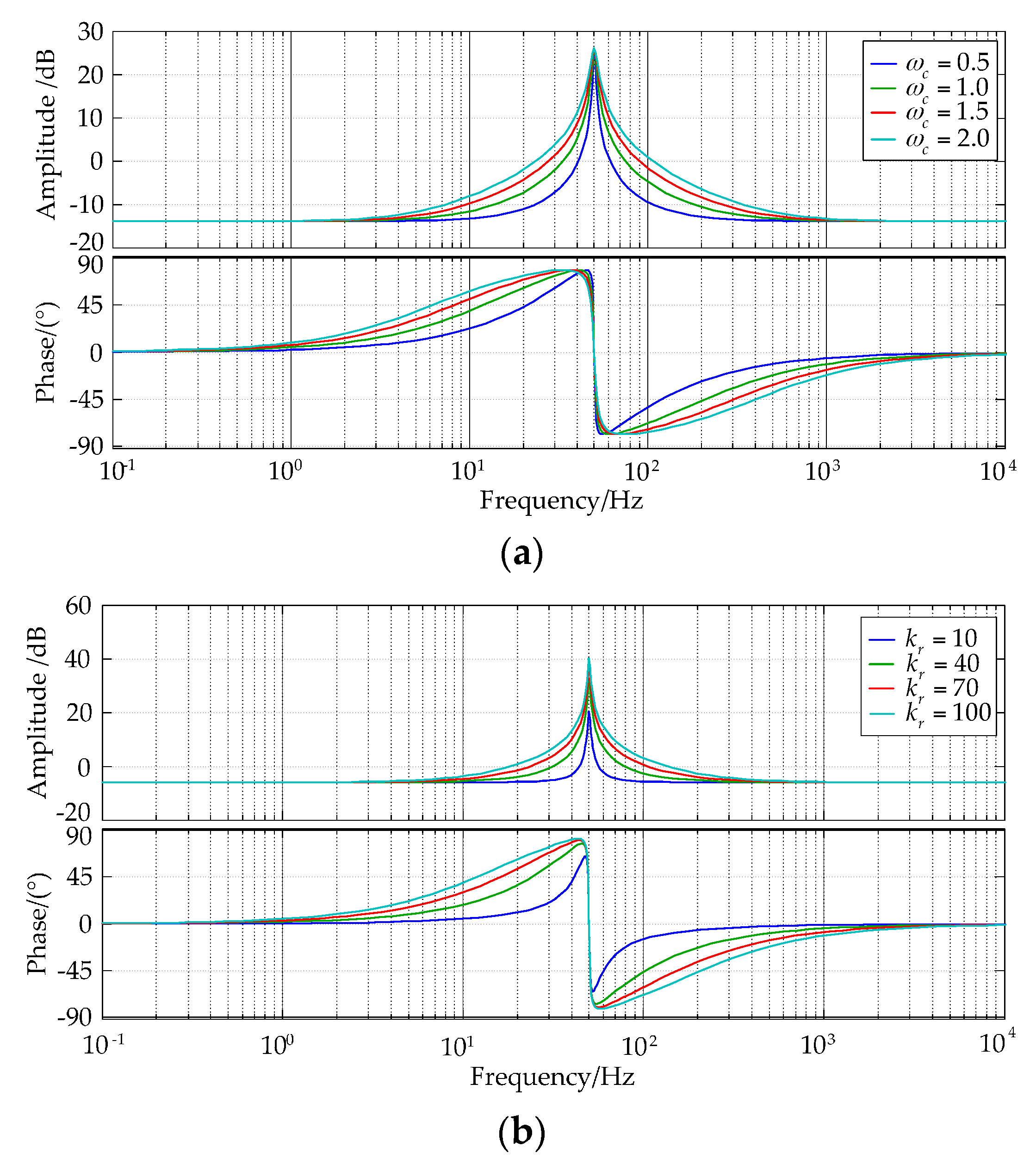
Figure 8 shows a Bode diagram of an improved PR controller with parameter variations. It can be seen from Figure 8 that when kr is constant, the gain and phase of the PR controller at the resonant frequency remains unchanged with the increase of ωc. ωc plays an important role in the bandwidth of controller. The larger ωc is, the greater the bandwidth of the controller is. At the same time, the frequency selective characteristic of the controller gets worse. If the ωc remains unchanged with the kr increases gradually, the bandwidth of the PR controller still remains unchanged, but the gain at the resonant point increases. The larger the kr is, the better the harmonic suppression effect can be. Considering the stability of the system, the value of kr should be moderate.
In order to simplify the analysis, the influence of the viscosity coefficient B is neglected and the current loop is considered ideal. When the DRPMSM turns into the single-redundancy operation mode due to short circuit fault, the original PI controller is connected in parallel with the improved PR controller. After incorporating the improved PR controller, the closed loop transfer function of the speed loop of the DRPMSM is given by
where
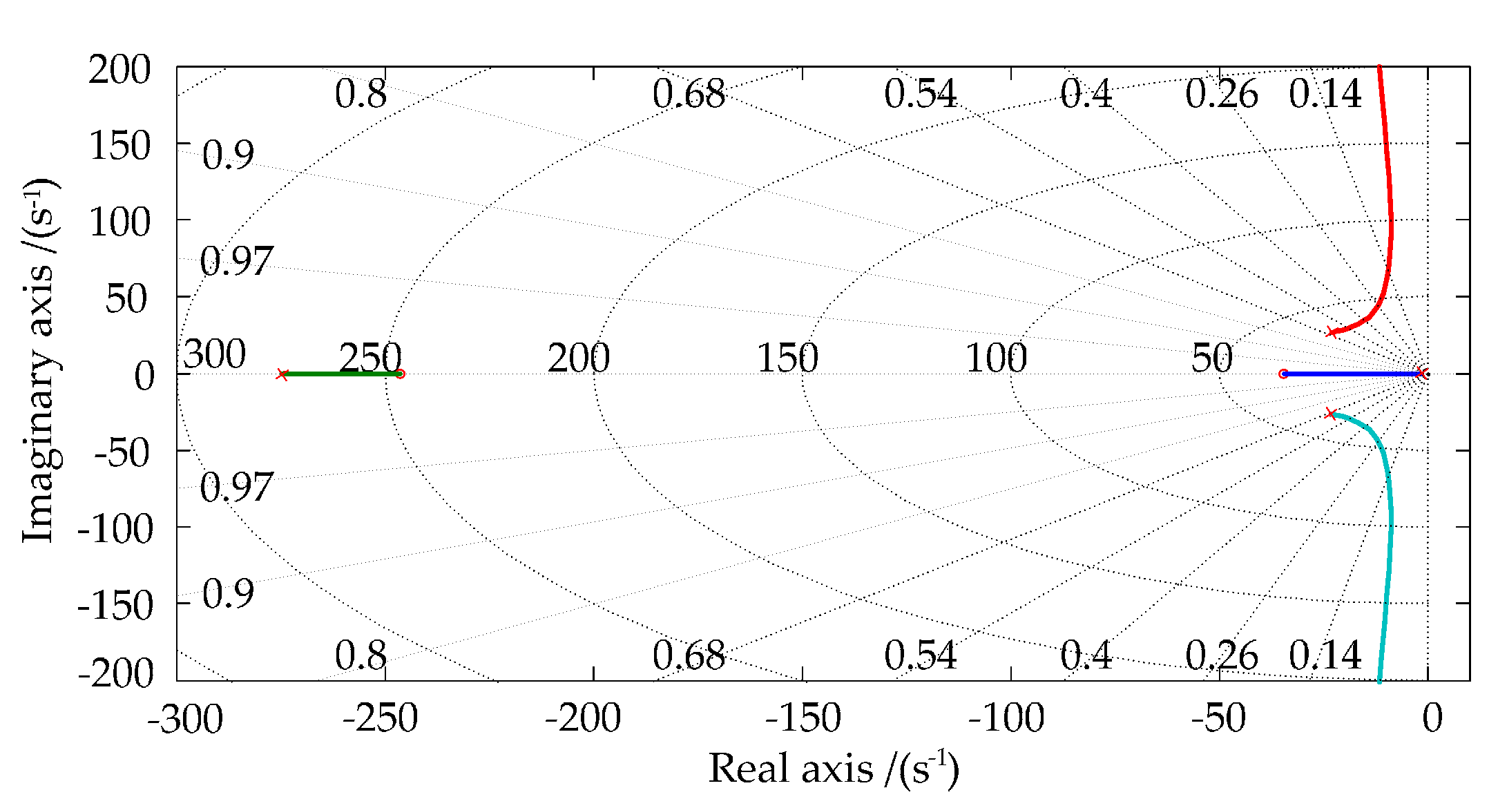
According to the generalized root locus analysis method, the (2ωe)2 is used as the parameter of the generalized root locus, and the equivalent open-loop transfer function is shown as follows:
The root locus drawn by Equation (45) is shown in Figure 9. When the other parameters of the system remain constant, the root locus of the closed-loop system is in the left half plane of the complex plane with the ωe increasing from 0 to +∞. Therefore, after the improved PR controller is incorporated into the speed loop, the whole system is stable at the full range of the motor speed.
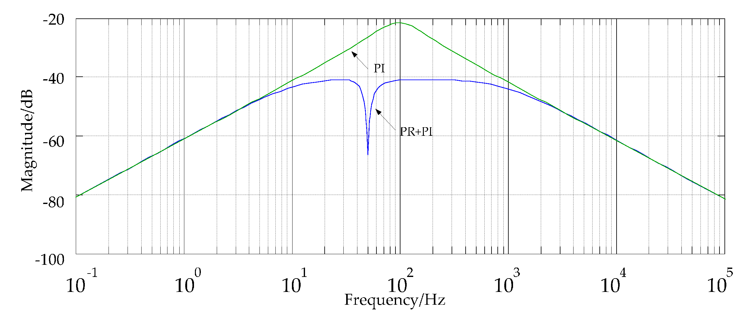
Amplitude-frequency curve from Ts~ to ω is shown in Figure 10. The traditional PI controller has a certain suppression effect on the torque ripple, but it can’t completely eliminate the influence caused by the torque ripple. The controller with PR and PI in parallel structure has a good suppression effect on the disturbance of the resonant frequency point because of the large gain at the resonant frequency.
The PI parameters are set to guarantee the overall performance of the speed loop, and the parameters of the resonant term are set up considering the stability and dynamic performance of the controller. The speed controller parameters Kp and ki2 should satisfy the following relationships:
where ωs represents the bandwidth of the speed loop; ki2 represents the integral coefficient.
The resonant coefficient kr in (43) determines the resonant controller’s response speed to the periodic signal. To determine the value of kr, there are two factors to be considered. Firstly, the kr value can’t be too large, otherwise it will reduce the resonant stability margin. Secondly, with the increase of the speed of the motor, the amplitude of the velocity fluctuation will decrease because of the filtering effect of the inertia moment. In order to increase the processing speed of the periodic signal, the resonant coefficient kr should be increased. Therefore, the value of kr in this paper is set as the value of rated speed [34].
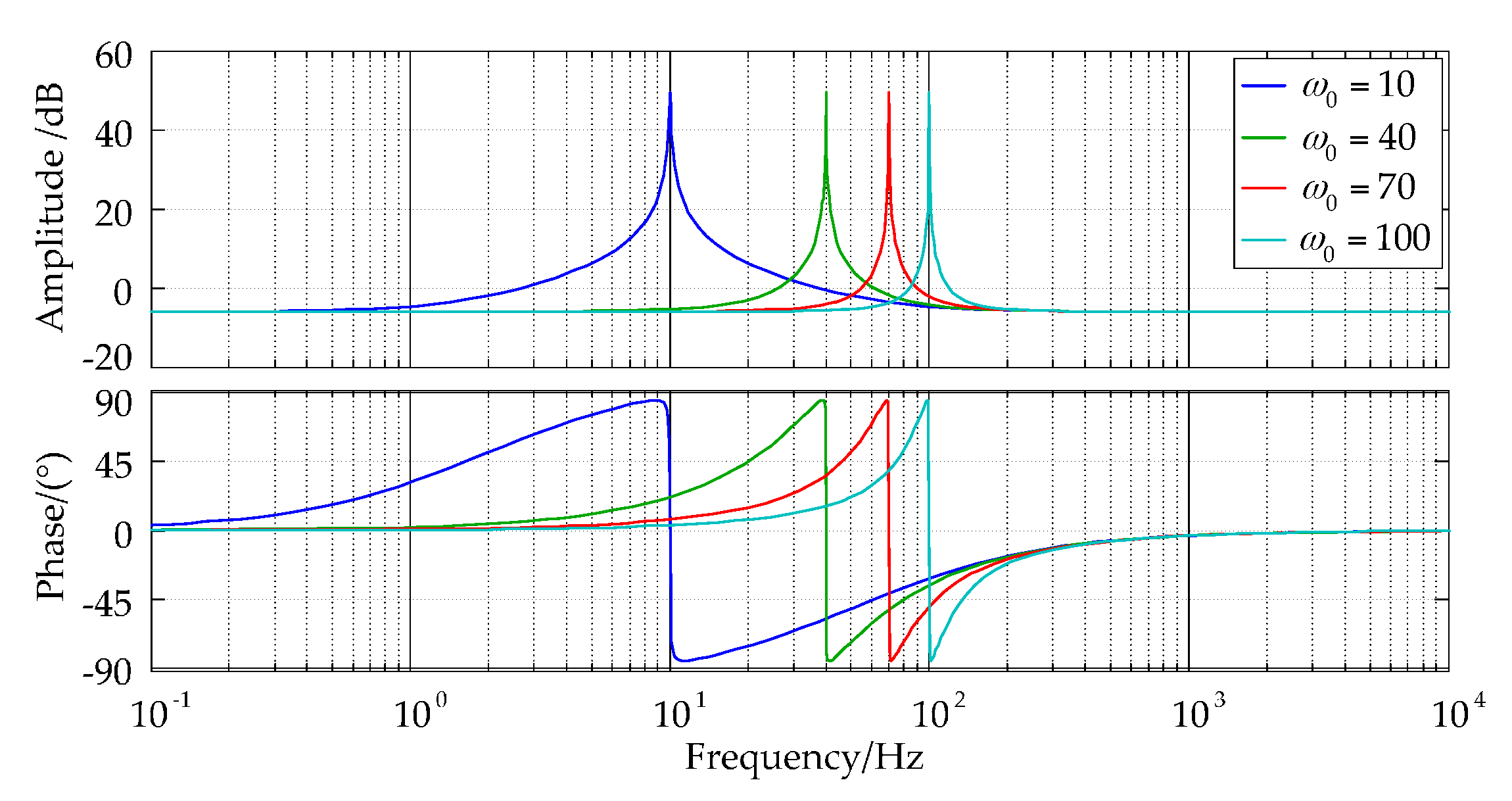
The improved PR controller can control the alternating current signal with fixed frequency, but the speed is not constant in the operation of the DRPMSM. Therefore, it is important to design a PR controller with variable resonant frequency to suppress torque ripple. From Figure 11, the improved PR controller shows good control performance by only changing ω0, while other parameters remain constant.
In order to suppress the torque ripple at different frequencies, ω0 needs to be used as input of the PR controller.
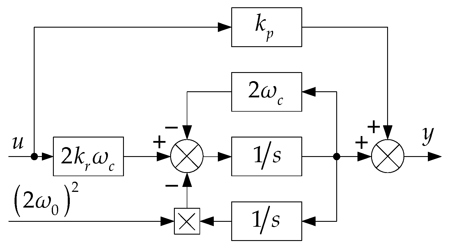
The improved adaptive PR controller is split into two integral links with a negative feedback structure as shown in Figure 12 [35,36]. In this case, the ω0 appears as a coefficient. Thus adaptive tuning of the resonance frequency is easy to achieve.
When the system encounters a short circuit fault, the faulty windings are removed and the DRPMSM works in single-redundancy operation mode. Taking the electrical angular velocity of the motor as the given value of ω0, the frequency adaptive PR controller is paralleled with the speed loop PI controller, so that the torque ripple caused by the short-circuit current can be suppressed at different speeds.
In digital systems, continuous control variables need to be discretized. If the Equation (43) is discretized by bilinear transformation, it is difficult to adjust the resonant frequency online [36]. The structure of Figure 12 shows that the improved PR controller is divided into two integral links, and the integral parts are discretized respectively. The resonant frequency is used as input so that the resonant frequency can be adjusted conveniently. The Forward Euler method is used in the forward path integral term for discretization, while the feedback channel integral term adopts the backward Euler method [36].
By substituting Equations (48) and (49) into Equation (43), the discrete transfer function of the resonant part can be obtained:
Finally, the differential equations of the system are obtained:
6. Simulation Results Analysis
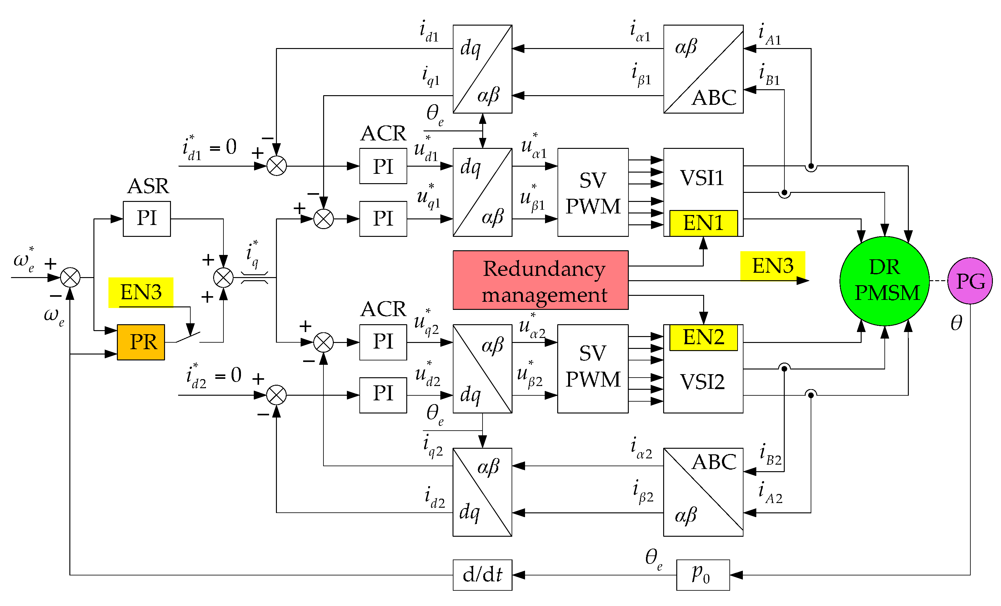
In order to verify the effectiveness of the proposed method, MATLAB/Simulink is used to build the model as shown in Figure 13. When one set of windings encounters the fault, the pulse width modulation (PWM) is locked in these windings by redundancy management. At the same time, an improved PR controller is paralleled with the PI controller in the speed loop.
The parameters of the DRPMSM are shown in Table 3. The SVPWM sampling frequency is set as 10 kHz. The DC bus voltage is 200 V.
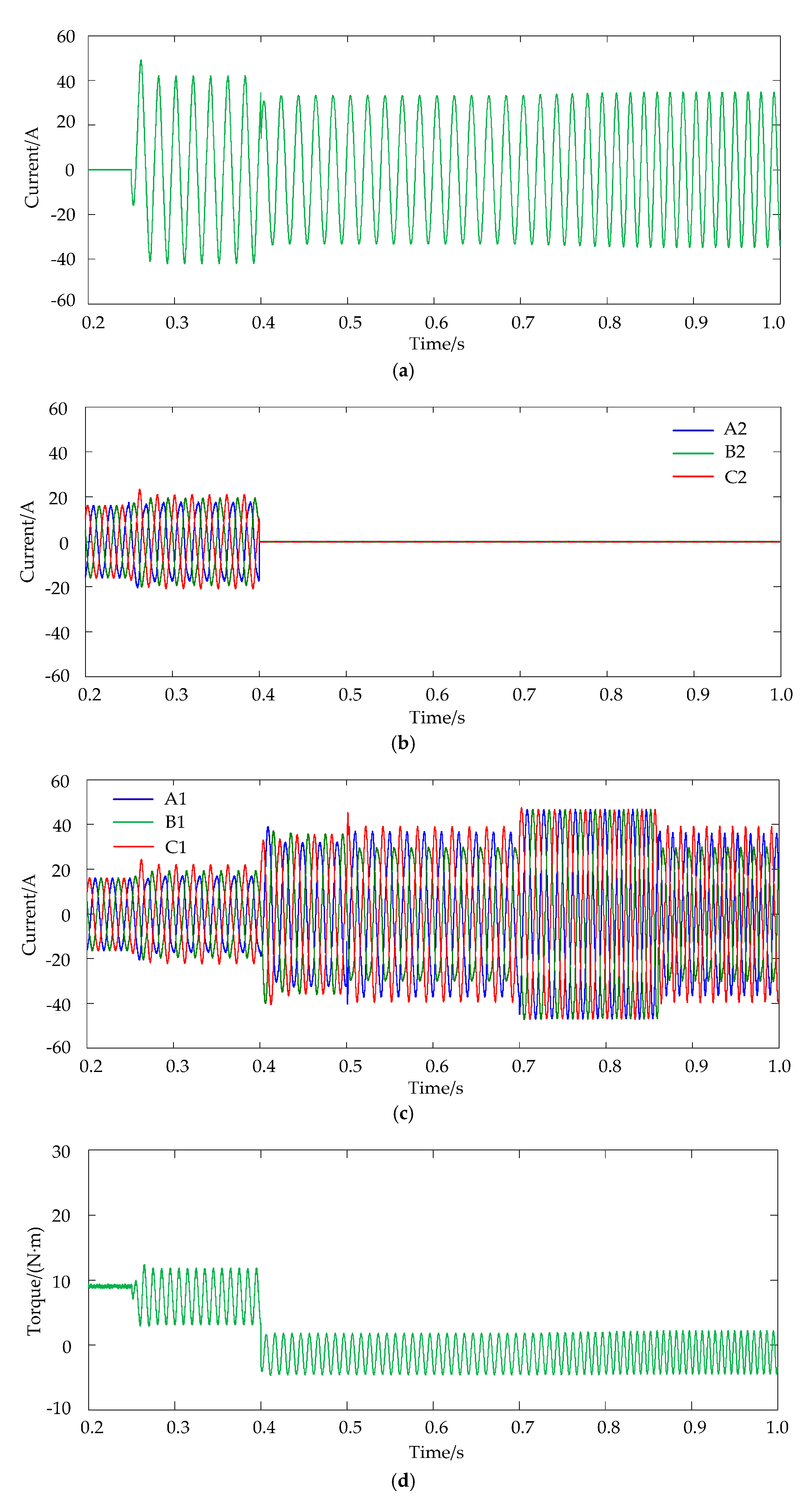
The whole simulation process is: at the beginning of 0.2 s, the motor is in dual-redundancy operation mode, and the speed is 600 r/min. The motor output electromagnetic torque is 18 N·m, about 70% of the rated electromagnetic torque. At 0.25 s, the reverse coils in the C2Z2 phase winding are shorted through a 0.1 Ω contact resistance. At 0.4 s, the power supply for the fault winding is cut off. The motor runs into the single-redundancy operation mode, and the remaining normal three-phase windings continue to work. At 0.5 s, the improved adaptive PR controller is incorporated into the speed loop. At 0.7 s, the given speed is set to 1000 r/min, and the motor accelerates and goes to the steady state. The simulation results are shown in Figure 14.
Figure 14a shows the current waveform that flows through the contact resistance. After a short circuit, the current amplitude becomes larger due to the partial current supplied by the inverter. After the power supply for the fault winding is cut off, the current in the contact resistance only comes from the short-circuit current generated by the permanent magnet EMF in inter-turn short-circuited coils, and the amplitude is smaller. The short-circuit current is mainly determined by the resistance of the short-circuited coils, and the amplitude of short-circuit current at 1000 r/min is slightly larger than that of 600 r/min.
The current waveforms of the three-phase winding with the fault coils and the normal three-phase winding are shown in Figure 14b,c respectively. The three-phase current waveforms of the two windings are the same before the coils are short-circuited. When the short circuit fault occurs, the system is affected by both the short-circuited coils and the speed controller, and the three-phase current distortion becomes heavier and the current amplitude increases slightly. At 0.4 s, the fault winding is removed, and only the normal winding is left. In order to maintain the same electromagnetic torque, the current of the normal winding need to double. At 0.5 s, the improved adaptive PR controller is added, and the rule of the three-phase current distortion is changed. The added distortion components in the three-phase current can compensate the electromagnetic torque ripple. The phase of the compensating electromagnetic torque is opposite to the electromagnetic torque generated by the short-circuited coils, by which the ripple electromagnetic torque generated by the short-circuited coils is suppressed. At 0.7 s, the given speed increases, and the amplitude of the normal three-phase winding current is limited due to the saturation of the speed loop. Meanwhile, the three-phase current is symmetric, and the motor begins to accelerate. When the speed reaches 1000 r/min, the change law of the short-circuit current and three-phase current is similar to that of 600 r/min.
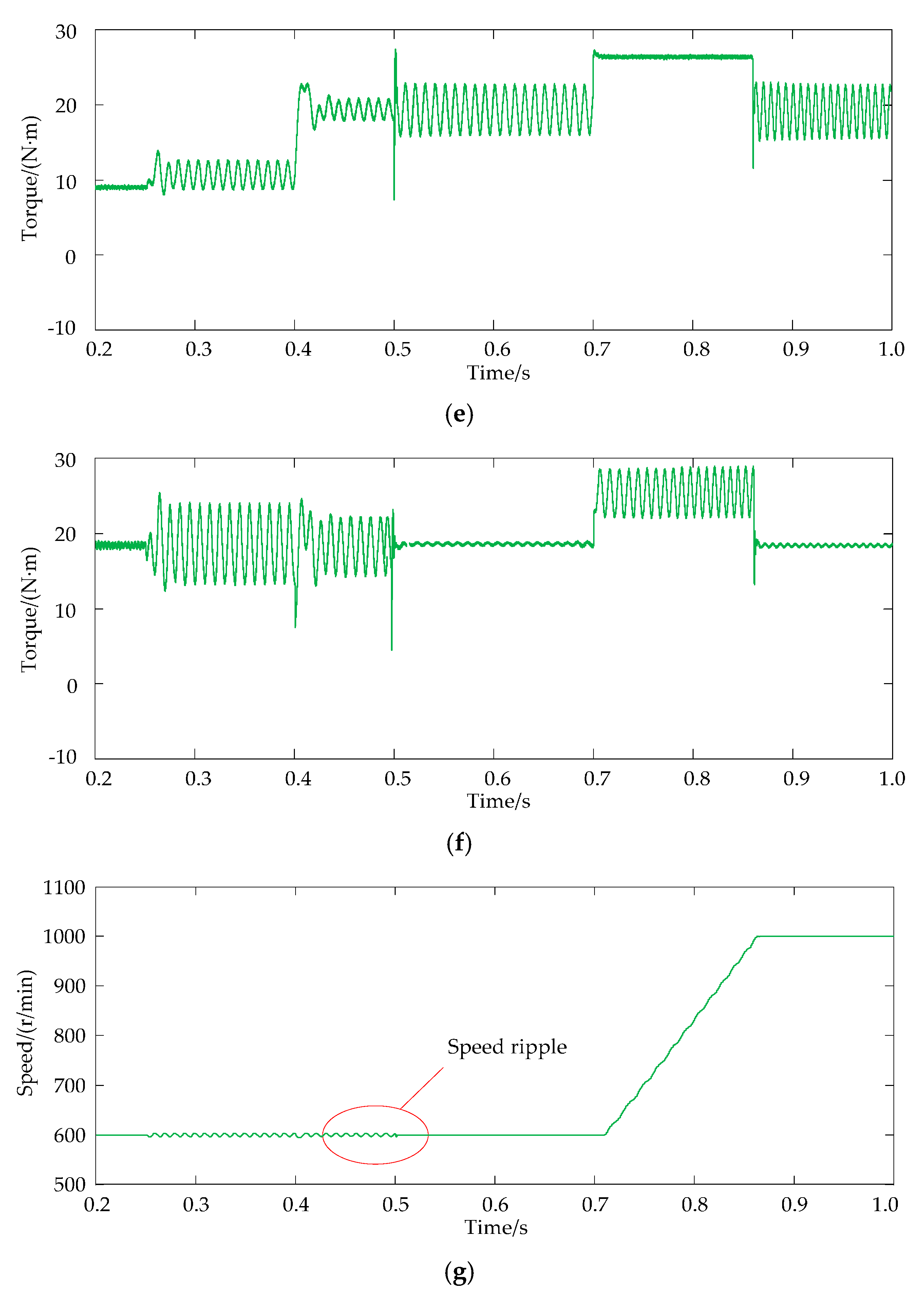
The electromagnetic torque of the three-phase winding with the fault coils, the normal three-phase winding and total electromagnetic torque of the motor are shown in Figure 14d, Figure 14e,f respectively. In dual-redundancy operation mode, the electromagnetic torque of both sets of windings is 9 N·m, and the total electromagnetic torque of the motor is 18 N·m with little ripple.
When the coils encounter an inter-turn short circuit, the short-circuit current not only produces a brake electromagnetic torque which is directly proportional to the copper loss of the short-circuited coils, but also generates a doubled-frequency electromagnetic torque ripple simultaneously.
When the coils are short-circuited, the average electromagnetic torque of three-phase winding with fault coils is about 8 N·m and the peak-to-peak value of the torque ripple is about 9 N·m. Due to the regulation of the speed controller, the normal three-phase winding also produces a torque ripple component about 4 N·m and the average electromagnetic torque value is about 10 N·m. The total electromagnetic torque of the motor is 18 N·m, and the peak-to-peak value of torque ripple is about 10 N·m. At 0.4 s, the power supply of the three-phase windings with fault coils is stopped. When the DRPMSM turns into single-redundancy operation mode, the electromagnetic torque of the fault set of three-phase windings is only generated by short-circuited coils. The braking electromagnetic torque is about 1 N·m, and the peak-to-peak value of torque ripple is about 5.5 N·m. The average electromagnetic torque of the normal set of three-phase winding is about 19 N·m, and the peak-to-peak value of torque ripple is about 2.5 N·m. The total electromagnetic torque of the motor is about 18 N·m, and the peak-to-peak value of the torque ripple is about 8 N·m. It can be seen that the torque ripple is 45.4% of the rated torque.
At 0.5 s, the improved adaptive PR controller is added. The electromagnetic torque of the normal windings compensates the torque ripple by changing its phase. The average value of electromagnetic torque is about 19 N·m, and the peak-to-peak value of the torque ripple is about 6.5 N·m. The average of the total output electromagnetic torque of the motor is still 18 N·m. The torque ripple dropped significantly, and the peak-to-peak value is only 1 N·m. It can be seen that the torque ripple reduces to 1 N·m (5.6%) which is greatly suppressed.
At 0.7 s, the given speed is set to 1000 r/min, and the motor starts to accelerate. The improved adaptive PR controller does not work temporarily and the PI controller output is quickly saturated. The current amplitude of the normal set of three-phase winding is constant, which generates constant electromagnetic torque electromagnetic torque about 28 N·m.
Because of the large inertia of the load, accelerating time is longer. When the speed reaches 1000 r/min, the improved adaptive PR controller can suppress the torque ripple again. The average value of the electromagnetic torque of the normal set of three-phase winding is about 19 N·m, and its peak-to-peak value of the torque ripple is about 7 N·m. The average output electromagnetic torque is still 18 N·m, but the torque ripple dropped drastically to a peak-to-peak value of only 0.8 N·m. The proposed method has reduced the torque ripple of the DRPMSM to 0.8 N·m that is 4.4% of the rated torque.
As is shown in Figure 14g, when the coil is short circuited, the speed of the motor will contain the second harmonic component if the improved adaptive PR controller is not adopted either in a dual-redundancy or a single-redundancy mode. The peak-to-peak value of speed ripple is about 8 r/min. When the improved adaptive PR controller is utilized, the ripple speed can be suppressed effectively as long as the motor runs in the steady state.
The simulation results show that the proposed method can effectively suppress the torque ripple caused by the electromagnetic torque of short-circuited coils.
7. Experimental Results Analysis
In order to verify the effectiveness of the method proposed in this paper, the control system of the DRPMSM is built based on the TI Company TMS320F2812 digital signal processor (DSP), as shown in Figure 15. Rotary transformers manufactured by Tamagawa Corporation of Japan are used to detect the rotor position. The resolver is transformed into a digital position signal by a special decoder chip AD2S1210, which is sent to the DSP chip. PWM signal is generated by the DSP to drive DRPMSM. During the experiment, the two coils of C2 phase windings are drawn out, and one of the coils is shorted by the contact resistance. At the same time, the PWM output of the fault windings is locked by redundancy management. The given speed is set as 600 r/min.
After the short circuit fault occurs, the total electromagnetic torque is difficult to measure. The electromagnetic torque of the normal windings is calculated by the q axis current and the permanent magnetic flux linkage.
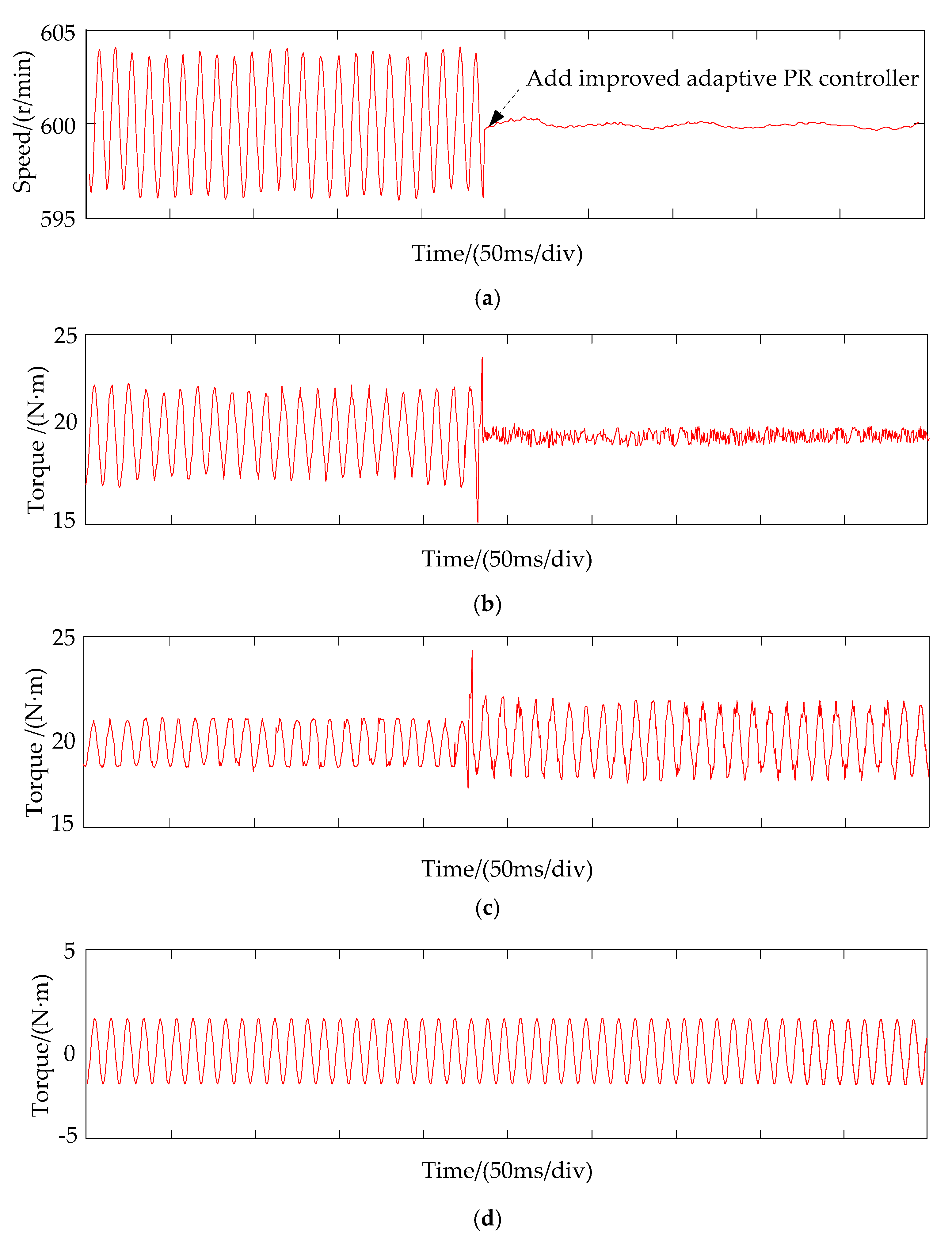
The experimental waveform of the speed is shown in Figure 16a. The peak-to-peak value of speed ripple is about 8 r/min before the improved adaptive PR controller is implemented. It can be seen from the speed waveform that the fluctuation of the speed is suppressed when the improved adaptive PR controller is added.
The waveform of the output electromagnetic torque at the 600 r/min is shown in Figure 16b. Through the electromagnetic torque waveform of the normal windings as shown in Figure 16c, the PI controller cannot restrain the disturbance caused by the short-circuited coils before the improved adaptive PR controller is added. After the improved adaptive PR controller is added, the alternating component in the electromagnetic torque of the normal windings shown in Figure 16c has a sudden change. As the amplitude increases, it compensates for the torque ripple generated by the short-circuited coils. Thus, the total output torque tends to be stable. The torque ripple drops significantly, and the peak-to-peak value is less than 1 N·m. Then, the speed is stabilized further. The torque generated by a short circuit is shown in Figure 16d.
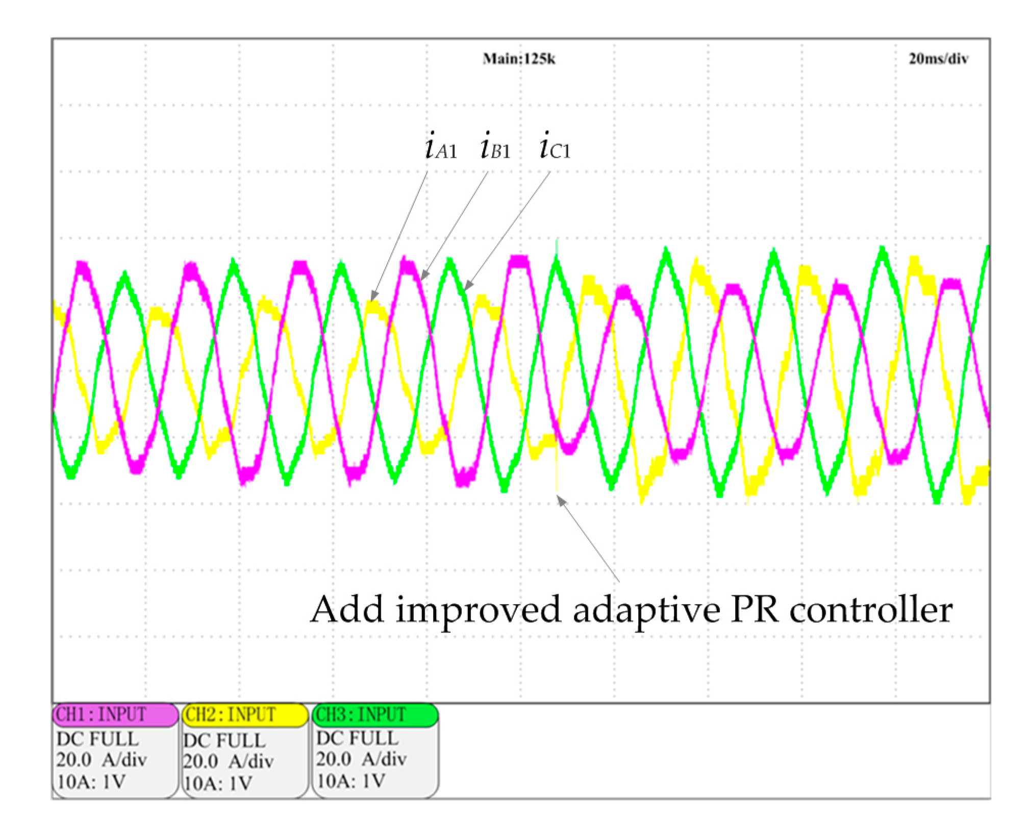
The waveform of the three-phase current is shown in Figure 17. When the improved adaptive PR controller is added, the change law of the three-phase current is changed, resulting in an electromagnetic torque that can suppress the torque ripple generated by the short-circuited coils.
8. Conclusions
The DRPMSM with weak thermal coupling and no electromagnetic coupling is analyzed in this paper. The short circuit fault of the DRPMSM is analyzed. When the motor is running in single-redundancy mode due to a short circuit fault, the short-circuited coils are in the power generation state, resulting in a constant braking torque and a torque ripple. In this paper, an adaptive improved PR controller parallel with the PI controller in the speed loop is proposed to suppress the torque ripple generated by the short-circuited coils. The main conclusions are as follows:
- (1)
- The mutual inductance between any two phases of the DRPMSM is proved to be zero by using the finite element method. The mutual inductance between phases is smaller than the phase winding inductance by at least two orders of magnitude. The faulty windings will have no electromagnetic effects on the normal windings. This will improve the reliability of the DRPMSM.
- (2)
- An adaptive improved PR controller parallel with the PI controller in the speed loop is proposed to suppress the torque ripple generated by the short-circuited coils. It can be seen from the simulation and experimental results that the peak-to-peak value of torque ripple decreased from 7 N·m to 1 N·m when the speed of the DRPMSM is 600 r/min. The torque ripple is 1 N·m which is significant as it is 5.6% of rated torque.
- (3)
- In the operation of DRPMSMs, short-circuit faults may occur at various speeds, and a frequency adaptive improved PR controller is adopted to suppress the short-circuited torque ripple at various speeds. The simulation results show that the proposed torque ripple suppression strategy can suppress torque ripple at various speeds of the DRPMSM.
The proposed torque ripple suppression method is a suitable control strategy for the DRPMSM under short circuit fault condition, which can improve operation performance of the DRPMSM in single operation mode. The DRPMSM with the proposed control strategy can improve the reliability of the system. When the winding fault occurs, it is important to diagnose the winding fault and remove the faulty winding in time. How to diagnose the winding fault can be investigated further in the future work.
Acknowledgments
This work is supported by The National Natural Science Foundation of China (No. 51377114).
Author Contributions
Yiguang Chen and Bo Zhang put forward the idea and theoretical verification. Yiguang Chen conceived and designed the proposed control methods. Yiguang Chen and Bo Zhang performed the experiments. Bo Zhang performed the simulation. Yiguang Chen and Bo Zhang analyzed the results. Bo Zhang made all graphics and wrote the paper.
Conflicts of Interest
The authors declare no conflict of interest.
References
- Zheng, P.; Wu, F.; Lei, Y.; Sui, Y.; Yu, B. Investigation of a novel 24-slot/14-pole six-phase fault-tolerant modular permanent-magnet in-wheel motor for electric vehicles. Energies 2013, 6, 4980–5002. [Google Scholar] [CrossRef]
- Cao, W.; Mecrow, B.C.; Atkinson, G.J.; Bennett, J.W.; Atkinson, D.J. Overview of electric motor technologies used for more electric aircraft (MEA). IEEE Trans. Ind. Electron. 2012, 59, 3523–3531. [Google Scholar]
- An, Q.T.; Liu, J.; Peng, Z.; Li, S.; Sun, L.Z. Dual-space vector control of open-end windings permanent magnet synchronous motor drive fed by dual inverter. IEEE Trans. Power Electron. 2016, 31, 8329–8342. [Google Scholar] [CrossRef]
- Yan, H.; Xu, Y.X.; Zou, J.B. A phase current reconstruction approach for three-phase permanent-magnet synchronous motor drive. Energies 2016, 9, 853. [Google Scholar] [CrossRef]
- Rehman, H. Detuning minimization of induction motor drive system for alternative energy vehicles. Energies 2015, 8, 9117–9136. [Google Scholar] [CrossRef]
- Zhao, Y.; Lipo, T.A. Space vector PWM control of dual three-phase induction machine using vector space decomposition. IEEE Trans. Ind. Appl. 1995, 31, 1100–1109. [Google Scholar] [CrossRef]
- Mecrow, B.C.; Jack, A.G.; Atkinson, D.J.; Green, S.R.; Atkinson, G.J.; King, A.; Green, B. Design and testing of a four-phase fault-tolerant permanent-magnet machine for an engine fuel pump. IEEE Trans. Energy Convers. 2004, 19, 671–678. [Google Scholar] [CrossRef]
- Huang, X.; Goodman, A.; Gerada, C.; Fang, Y.; Lu, Q. Design of a five-phase brushless dc motor for a safety critical aerospace application. IEEE Trans. Ind. Electron. 2012, 59, 3532–3541. [Google Scholar] [CrossRef]
- Bianchi, N.; Bolognani, S.; Pré, M.D. Design of a Fault-tolerant IPM Motor for Electric Power Steering. IEEE Trans. Veh. Technol. 2005, 55, 1102–1111. [Google Scholar] [CrossRef]
- Fang, S.; Zhou, B.; Liu, Y. Design and realization of dual redundancy PMSM electrical drive systems. In Proceedings of the IEEE Conference on Industrial Electronics and Applications (ICIEA), Xi’an, China, 25–27 May 2009; pp. 1985–1989. [Google Scholar]
- Hoang, K.D.; Ren, Y.; Zhu, Z.Q.; Foster, M. Modified switching-table strategy for reduction of current harmonics in direct torque controlled dual-three-phase permanent magnet synchronous machine drives. IET Electr. Power Appl. 2015, 9, 10–19. [Google Scholar] [CrossRef]
- Sant, A.V.; Khadkikar, V.; Xiao, W.; Zeineldin, H.H. Four-axis vector-controlled dual-rotor PMSM for plug-in electric vehicles. IEEE Trans. Ind. Electron. 2015, 62, 3202–3212. [Google Scholar] [CrossRef]
- Hu, Y.S.; Zhu, Z.Q.; Liu, K. Current control for dual three-phase permanent magnet synchronous motors accounting for current unbalance and harmonics. IEEE J. Emerg. Sel. Top. Power Electron. 2014, 2, 272–284. [Google Scholar]
- Karttunen, J.; Kallio, S.; Peltoniemi, P.; Silventoinen, P.; Pyrhönen, O. Decoupled vector control scheme for dual three-phase permanent magnet synchronous machines. IEEE Trans. Ind. Electron. 2013, 61, 2185–2196. [Google Scholar] [CrossRef]
- Hu, S.; Liang, Z.; Zhang, W.; He, X. Research on the integration of hybrid energy storage system and dual three-phase PMSM drive in EV. IEEE Trans. Ind. Electron. 2017, 99. [Google Scholar] [CrossRef]
- Demir, Y.; Aydin, M. A novel dual three-phase permanent magnet synchronous motor with asymmetric stator winding. IEEE Trans. Magn. 2016, 52, 1–5. [Google Scholar] [CrossRef]
- Wang, W.; Zhang, J.; Cheng, M.; Li, S. Fault-tolerant control of dual three-phase permanent-magnet synchronous machine drives under open-phase faults. IEEE Trans. Power Electron. 2016, 32, 2052–2063. [Google Scholar] [CrossRef]
- Jiang, X.F.; Huang, W.X.; Cao, R.G.; Hao, Z.Y.; Jiang, W. Electric drive system of dual-windings fault-tolerant permanent-magnet motor for aerospace applications. IEEE Trans. Ind. Electron. 2015, 62, 7322–7330. [Google Scholar] [CrossRef]
- Vaseghi, B.; Takorabet, N.; Caron, J.P.; Nahid-Mobarakeh, B.; Meibody-Tabar, F.; Humbert, G. Study of different architectures of fault-tolerant actuator using a two-channel PM motor. IEEE Trans. Ind. Appl. 2011, 47, 47–54. [Google Scholar] [CrossRef]
- Liang, Z.; Kou, P.; Liang, D. A fault tolerant control strategy for dual three-phase permanent magnet synchronous motor servo system based on frequency domain analysis. In Proceedings of the Eleventh International Conference on Ecological Vehicles and Renewable Energies (EVER), Monte Carlo, Monaco, 6–8 April 2016; pp. 1–13. [Google Scholar]
- Velly, N.; Takorabet, N.; Meibody-Tabar, F.; Liegeois, P.Y.; Nierlich, F.; Leynaert, F.N.; Humbertet, G. Double channel PM motor for avionic applications: Impact of winding topologies. In Proceedings of the IEEE Energy Conversion Congress and Exposition (ECCE), Milwaukee, WI, USA, 18–22 September 2009; pp. 2387–2394. [Google Scholar]
- Chen, Y.G.; Zhai, W.C.; Shen, Y.H. Analysis on temperature field distribution of dual-redundancy PMSM. J. Tianjin Univ. 2015, 488–493. [Google Scholar]
- Zhao, W.; Cheng, M.; Chau, K.T.; Hua, W.; Jia, H.Y.; Ji, J.H.; Li, W.L. Stator-flux-oriented fault-tolerant control of flux-switching permanent-magnet motors. IEEE Trans. Magn. 2011, 47, 4191–4194. [Google Scholar] [CrossRef] [Green Version]
- Wu, F.; Tong, C.; Sui, Y.; Cheng, L.M.; Zheng, P. Influence of third harmonic back EMF on modeling and remediation of windings short circuit in a multiphase PM machine with FSCWs. IEEE Ind. Electron. Soc. 2016, 63, 6031–6041. [Google Scholar] [CrossRef]
- Zhao, H.S.; Ge, B.J.; Tao, D.J.; Wen, R.X.; Xing, G. Influence of stator windings inter-turn short-circuit fault on generator electromagnetic torque characteristics. Trans. China Electrotech. Soc. 2016, 31, 192–198. [Google Scholar]
- Fang, C.; Xu, H.P.; Xue, S.S.; Huang, Q.P.; Xue, S. Torque ripple and losses of direct-drive multi-phase permanent magnet synchronous machines. Trans. China Electrotech. Soc. 2014, 29, 149–159. [Google Scholar]
- Viswanathan, V.; Jeevananthan, S. Commutation torque ripple reduction in BLDC motor using modified SEPIC converter and three-level NPC inverter. IEEE Trans. Power Electron. 2017, 33, 535–546. [Google Scholar] [CrossRef]
- Tischer, C.B.; Tibola, J.R.; Scherer, L.G.; de Camargo, R.F. Proportional-resonant control applied on voltage regulation of standalone SEIG for micro-hydro power generation. IET Renew. Power Gener. 2017, 11, 593–602. [Google Scholar] [CrossRef]
- Komurcugil, H.; Altin, N.; Ozdemir, S.; Sefa, I. Lyapunov-function and proportional-resonant-based control strategy for single-phase grid-connected VSI with LCL filter. IEEE Trans. Ind. Electron. 2016, 63, 2838–2849. [Google Scholar] [CrossRef]
- Chen, Y.G.; Pan, Y.L.; He, X. Magnetomotive force in permanent magnet synchronous machine with concentrated fractional-slot windings. Trans. China Electrotech. Soc. 2010, 25, 30–36. [Google Scholar]
- Shen, G.; Zhu, X.; Zhang, J.; Xu, D. A new feedback method for PR current control of LCL-filter-based grid-connected inverter. IEEE Trans. Ind. Electron. 2010, 57, 2033–2041. [Google Scholar] [CrossRef]
- Devassy, S.; Singh, B. Performance analysis of proportional resonant and ADALINE-based solar photovoltaic-integrated unified active power filter. IET Renew. Power Gener. 2017, 11, 1382–1391. [Google Scholar] [CrossRef]
- Guo, X.Q.; Hao, W.Y.; Zhao, Q.L. Comparative analysis and digital implementation of novel control strategies for grid-connected inverters. Trans. China Electrotech. Soc. 2007, 22, 111–116. [Google Scholar]
- Xia, C.L.; Ji, B.; Yan, Y. Smooth Speed Control for Low-Speed High-Torque Permanent-Magnet Synchronous Motor Using Proportional-Integral-Resonant Controller. IEEE Trans. Ind. Electron. 2015, 62, 2123–2134. [Google Scholar] [CrossRef]
- Yepes, A.G.; Freujedo, F.D.; Lopez, O.; Doval-Gandoy, J. High-performance digital resonant controllers implemented with two integrators. IEEE Trans. Power Electron. 2011, 26, 563–576. [Google Scholar] [CrossRef]
- Yepes, A.G.; Freijedo, F.D.; Lopez, O.; Doval-Gandoy, J. Correction to high performance digital resonant controllers implemented with two integrators. IEEE Trans. Power Electron. 2012, 27, 4357. [Google Scholar] [CrossRef]
Figure 1.
Cross-sectional view of the DRPMSM.

Figure 2.
Stator windings outspread diagram of the DRPMSM.
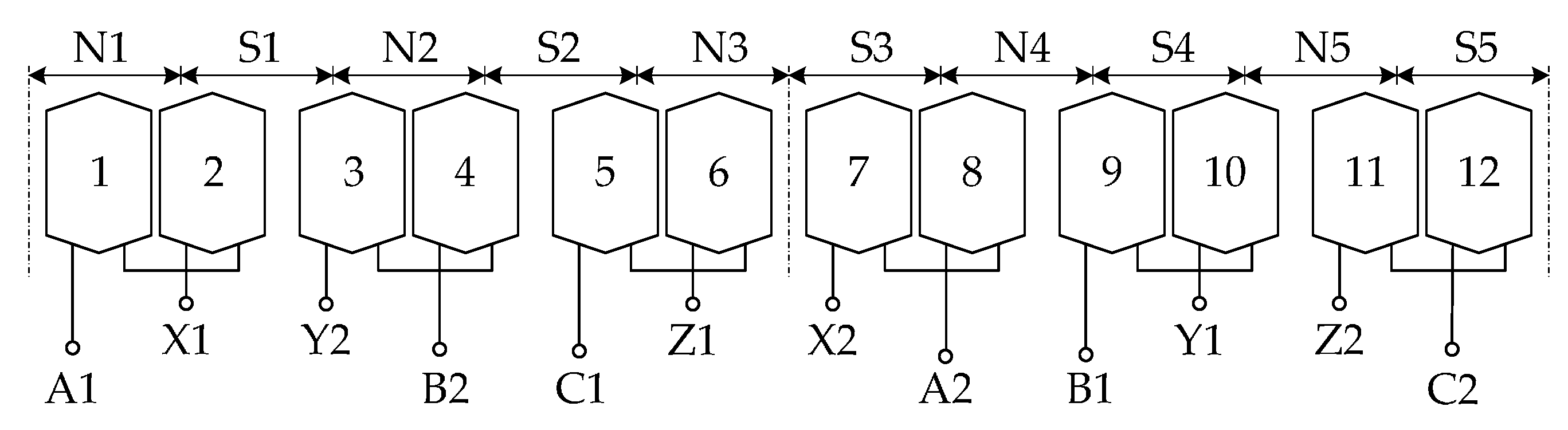
Figure 3.
Structure and drive system topology structure of the DRPMSM.
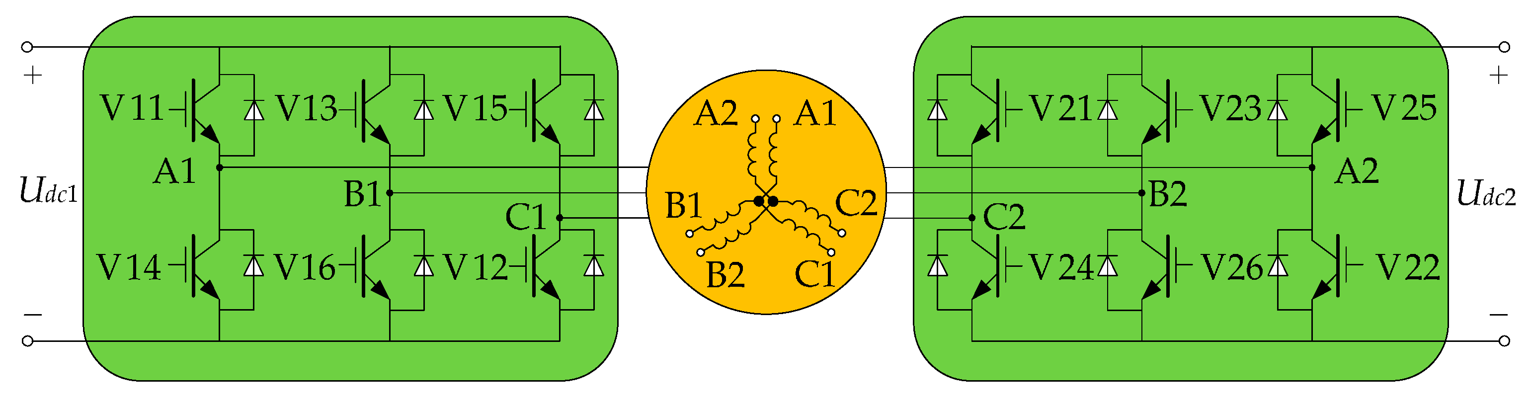
Figure 4.
Equivalent circuit of coils inter-turn short circuit.

Figure 5.
Transfer function of DRPMSM control system.
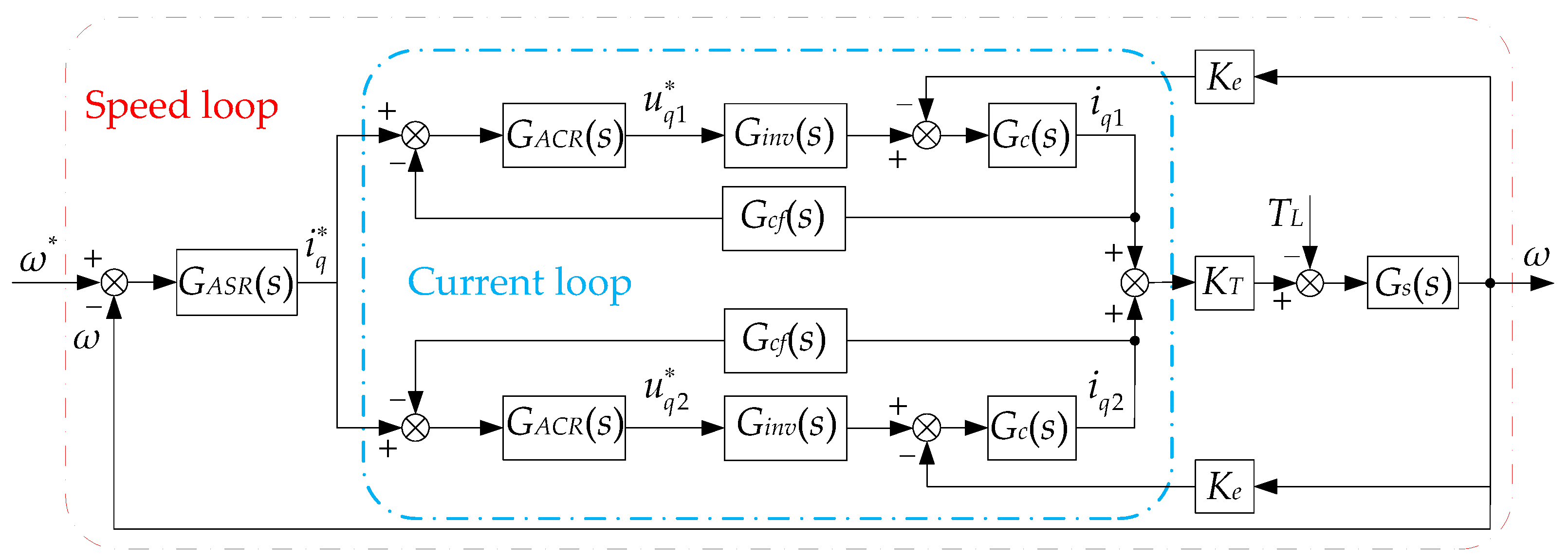
Figure 6.
The transfer function of speed loop.

Figure 7.
Bode diagram of PR controller and improved PR controller.
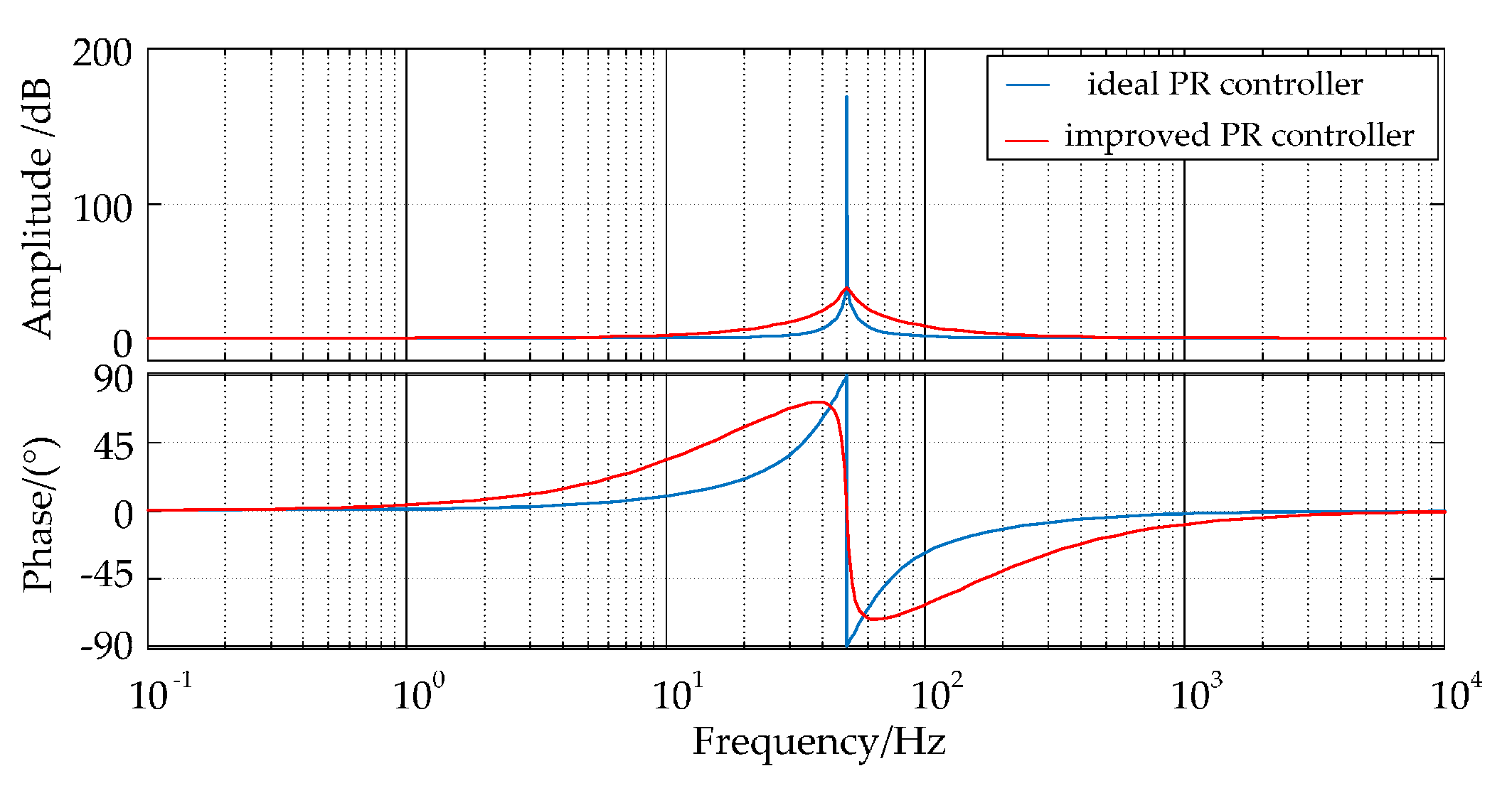
Figure 8.
Bode diagram of the improved PR controller with parameters varying: (a) kp = 20, kr = 20, the bode diagram of different ωc; (b) kp = 20, ωc = 0.5, the bode diagram of different kr.
Figure 8.
Bode diagram of the improved PR controller with parameters varying: (a) kp = 20, kr = 20, the bode diagram of different ωc; (b) kp = 20, ωc = 0.5, the bode diagram of different kr.

Figure 9.
The root locus of the closed loop system after adding the improved PR controller.

Figure 10.
Amplitude-frequency curve from disturbance torque to speed.

Figure 11.
Bode diagram of improved PR controllers with different resonant frequencies.

Figure 12.
Improved adaptive PR controller.

Figure 13.
Control system of dual-redundancy permanent magnet synchronous motor based on PR.

Figure 14.
The waveform of simulation: (a) The current waveform of contact resistance; (b) The three-phase current waveform of fault windings; (c) The three-phase current waveform of normal windings; (d) The electromagnetic torque of fault windings; (e) The electromagnetic torque of normal windings; (f) The output electromagnetic torque; (g) The waveform of speed.


Figure 15.
Experimental system diagram of DRPMSM.
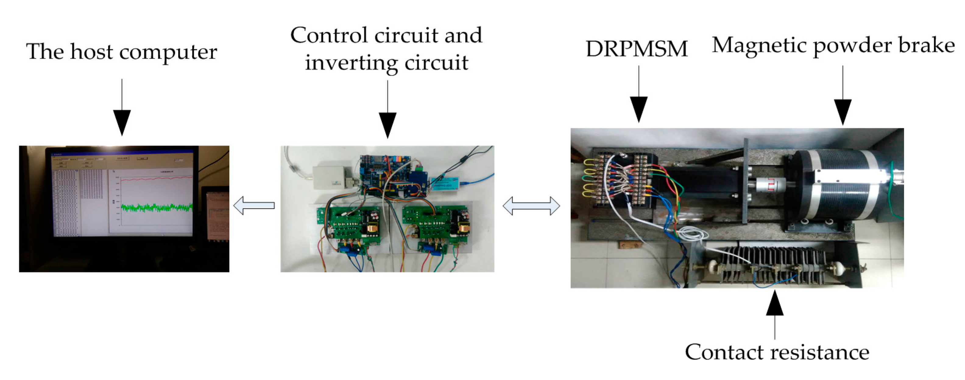
Figure 16.
The experimental waveform: (a) The waveform of speed; (b) The output electromagnetic torque; (c) The electromagnetic torque of normal windings; (d) The electromagnetic torque produced by short-circuited coils.
Figure 16.
The experimental waveform: (a) The waveform of speed; (b) The output electromagnetic torque; (c) The electromagnetic torque of normal windings; (d) The electromagnetic torque produced by short-circuited coils.

Figure 17.
The current waveform of DRPMSM.

Table 1.
The structural parameters of the DRPMSM.
| Parameters | Value |
|---|---|
| Core length/mm | 150 |
| Outer diameter of stator/mm | 120 |
| Inner diameter of stator/mm | 61 |
| Outer diameter of rotor/mm | 58 |
| Permanent magnet thickness L | 4.46 |
| Air gap length/mm | 1.5 |
| Slot width/mm | 2.5 |
| Lamination factor of stator/mm | 0.95 |
| Tooth depth/mm | 22.5 |
Table 2.
The inductance matrix of the DRPMSM.
| L/mH | A1 | B1 | C1 | A2 | B2 | C2 |
|---|---|---|---|---|---|---|
| A1 | 2.19 | 1.31 × 10⁻² | 5.47 × 10⁻⁵ | 5.09 × 10⁻⁵ | 6.38 × 10⁻⁵ | 1.42 × 10⁻² |
| B1 | 1.31 × 10⁻² | 2.19 | 1.44 × 10⁻² | 6.42 × 10⁻⁵ | 4.85 × 10⁻⁵ | 5.68 × 10⁻⁵ |
| C1 | 5.47 × 10⁻⁵ | 1.44 × 10⁻² | 2.19 | 1.40 × 10⁻² | 5.69 × 10⁻⁵ | 5.65 × 10⁻⁵ |
| A2 | 5.09 × 10⁻⁵ | 6.42 × 10⁻⁵ | 1.40 × 10⁻² | 2.19 | 1.32 × 10⁻² | 5.45 × 10⁻⁵ |
| B2 | 6.38 × 10⁻⁵ | 4.85 × 10⁻⁵ | 5.69 × 10⁻⁵ | 1.32 × 10⁻² | 2.19 | 1.44 × 10⁻² |
| C2 | 1.42 × 10⁻² | 5.68 × 10⁻⁵ | 5.65 × 10⁻⁵ | 5.45 × 10⁻⁵ | 1.44 × 10⁻² | 2.19 |
Table 3.
Parameters of DRPMSM.
| Parameters | Value |
|---|---|
| Rated power PN | 3.5 kW |
| Rated speed n | 1200 r/min |
| Rated current IN | 17.7 A |
| Pole pairs p0 | 5 |
| Phase inductance L | 2.19 mH |
| Phase resistance R | 0.157 Ω |
| Permanent magnetic flux ψM | 0.094 Wb |
| System inertia J | 0.055 kg·m2 |
© 2017 by the authors. Licensee MDPI, Basel, Switzerland. This article is an open access article distributed under the terms and conditions of the Creative Commons Attribution (CC BY) license (http://creativecommons.org/licenses/by/4.0/).
Share and Cite
MDPI and ACS Style
Chen, Y.; Zhang, B. Minimization of the Electromagnetic Torque Ripple Caused by the Coils Inter-Turn Short Circuit Fault in Dual-Redundancy Permanent Magnet Synchronous Motors. Energies 2017, 10, 1798. https://doi.org/10.3390/en10111798
AMA Style
Chen Y, Zhang B. Minimization of the Electromagnetic Torque Ripple Caused by the Coils Inter-Turn Short Circuit Fault in Dual-Redundancy Permanent Magnet Synchronous Motors. Energies. 2017; 10(11):1798. https://doi.org/10.3390/en10111798
Chicago/Turabian StyleChen, Yiguang, and Bo Zhang. 2017. "Minimization of the Electromagnetic Torque Ripple Caused by the Coils Inter-Turn Short Circuit Fault in Dual-Redundancy Permanent Magnet Synchronous Motors" Energies 10, no. 11: 1798. https://doi.org/10.3390/en10111798
Note that from the first issue of 2016, this journal uses article numbers instead of page numbers. See further details here.