Article

A Real-Time Digital Solver for Smart Substation Based on Orders

The Key Laboratory of Smart Grid of Ministry of Education, Tianjin University, Tianjin 300072, China
*
Author to whom correspondence should be addressed.
Energies 2017, 10(11), 1795; https://doi.org/10.3390/en10111795
Submission received: 1 October 2017 / Revised: 2 November 2017 / Accepted: 3 November 2017 / Published: 7 November 2017
(This article belongs to the Section F: Electrical Engineering)

Abstract

:
In order to expand the simulation scale of smart substation, a simulation model of the inlet-outlet line unit, as described by the 0/108 S conductance for multivalued coefficients pre-storage is presented in this paper. As a part of orders decomposition, the address conversion circuit for multivalued coefficients can reduce the computational burden of processing elements. For the convenience of the generalization of the real-time digital solver based on FPGA (FRTDS, FPGA: Field–Programmable Gate Array), the address conversion circuit for multivalued coefficients is matched with the guide word, the formation module of sampled value (SV) packet, and the resolution module of generic object oriented substation event (GOOSE) packet are associated with the application identification (APPID) in the Ethernet frame. The address conversion circuit for multivalued coefficients, the formation module of SV packet, and the resolution module of GOOSE packet are reconstructed via the orders. A hardware-in-the-loop real-time simulation platform for smart substation is built based on the novel FRTDS. A case is given to demonstrate the simulation calculating capability and the hardware-in-the-loop ability of the novel FRTDS.

1. Introduction

As the trend of power grid, smart grid has penetrated into power generation, transmission, transformation, distribution, consumption, scheduling, and communication. Power transformation is the core of smart grid. At present, the substation is changing from the conventional substation to the smart substation. In the smart substation, the traditional current transformers and circuit breakers are replaced by the new electronic current transformers and smart circuit breakers, the secondary circuit cable connection is replaced by the high-speed Ethernet communication. IEC 61850 series communication standards have solved the issues of information sharing between different equipment, which implement the full digitization of substation, the networking of communication platform, the standardization of information sharing [1,2,3].
Many colleges and research institutions use real-time digital simulator (RTDS) and digital dynamic real-time simulator (DDRTS) to establish various hardware-in-the-loop real-time simulation systems, which can accomplish the dynamic performance test for control equipment and management system of the smart substation. These simulation systems play a very important role in the development of the smart substation [4,5]. RTDS and its giga-transceiver network communication (GTNET) card are used to study the transmission of packets in the smart substation in [6], which realizes the closed loop test of the digital relay protection device. The signal concurrency of the multi-channel merging unit and the simulation synchronization of analog and digital quantity are solved in [7], which realizes the closed loop test of the operation monitoring devices. The core of these real-time simulation platforms is either the central processing unit (CPU) or the digital signal processing (DSP). The calculating ability of its monomer is limited, and the clustering method is usually used to complete the large-scale electromagnetic transient real-time simulation of the smart substation. However, the establishment of a large-scale hardware-in-the-loop real-time simulation system for the smart substation based on RTDS or DDRTS requires huge amounts of funding, so it is difficult to promote these real-time simulation platforms to the general research institutions and colleges, let alone to the technical training in the power department.
Field programmable gate array (FPGA) has a fully configurable parallel hardware structure, distributed memory structure and deep pipeline structure, which can achieve a high degree of parallel numerical calculation. Moreover, FPGA has the advantages of low cost, small size, and it has been widely applied in the real-time simulation of power systems [8,9,10]. The real-time simulation of active distribution network with modular structure design is realized in [11,12], which introduced the implementation of several key modules as well. Multi-FPGA electromagnetic transient real-time simulation is achieved for large-scale power system based on modular structure design in [13]. The hardware circuits in these references are designed according to the calculation characteristics of electromagnetic transient simulation, which can minimize the simulation time, but it requires the programmers to have high-level of FPGA programming skills and power system expertise. Real-time digital solver based on FPGA (FRTDS), developed by the Tianjin University key laboratory of smart grid of ministry of education encapsulates the commonly used expressions and functions in the processing element (PE). The orders are simulation program instructions flow, like assembly language, which are used to make PEs work regularly, and the compile software from the simulation script to the orders is proposed. It makes electrical engineers with a general beginner’s all-purpose symbolic instruction code (BASIC) programming ability can design new simulation applications. Since the price of FRTDS is relatively cheap and the simulation script is easy to write, it has been successfully applied to the conventional substation simulation training system.
On one hand, the real-time simulation speed improvement of the substation depends on the hardware condition of the simulation platform; on the other hand, it is related to the simulation algorithm. The network is divided into the sub-layer and parent layer in [14], first, the multiport hybrid equivalent is implemented to the sub-layer network, then, and the voltage of sub-layer network interface is acquired through solving the parent layer network equations. Finally, the internal electrical quantities of sub-layer network are solved. However, the external equivalent and internal electric quantities of sub-layer network are solved by the node voltage equation or the state equation, which severely limits the simulation speed. The switch is described by the two-valued conductance model in [15], the inverse matrix is pre-storage in memory blocks for the real-time simulation, but the memory requirement for inverse matrix is prohibitively intolerable when it is applied to real-time simulation of the large-scale substation.
The main contribution of this paper is to establish the equivalent model of the inlet-outlet line unit, which is described by the 0/108 S conductance for the multivalued coefficients pre-storage. Moreover, the query circuit of the multivalued coefficients, which is used to address the actual value, is designed according to the proposed address transformation algorithm. Meanwhile, in order to facilitate the communication with the secondary equipment of the smart substation, the Ethernet communication interface and packet service modules are constructed. Specifically, the contribution of this paper is as follows:
(1)
The equivalent model of the inlet-outlet line unit is established, which can reduce the scale of the substation real-time simulation and improve the simulation speed by pre-storing the equivalent conductivity and voltage coefficients.
(2)
The special address query circuit of the multivalued coefficients is designed, which associates the address transformation algorithm with the multivalued coefficients guide word. This addressing process is completed in the orders, which is independent of the simulation calculation, with a good scalability.
(3)
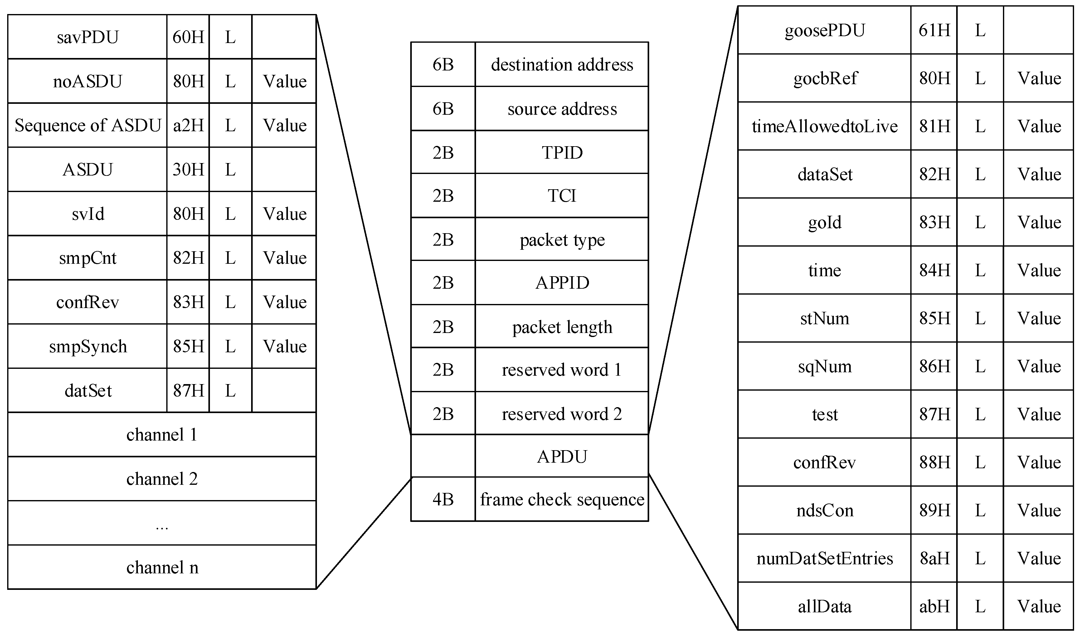
The formation of SV packet and the resolution of GOOSE packet are implemented in FRTDS in the form of orders. The template modification service module and the state extraction service module are designed to solve the uncertainty of SV and GOOSE packet structure.

2. FRTDS

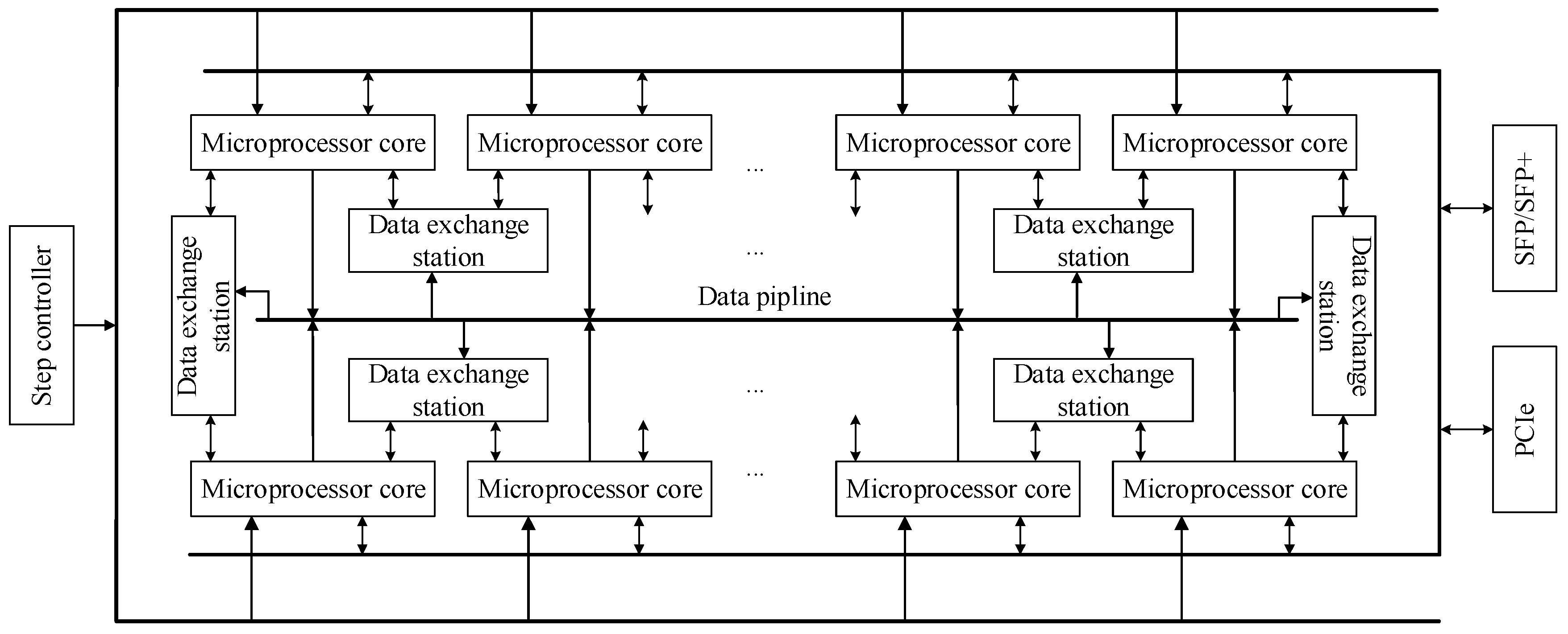
2.1. Microprocessor Core

The core of FRTDS is the microprocessor core. Each microprocessor core contains processing elements, control unit, data storage unit, and order storage unit. Every processing element has data input ports, data output ports, and function control ports. Arithmetic expression circuits, logic expression circuits, comparison expression circuits, function circuits, and data transmission circuits are encapsulated in the processing element. The reuse technology is applied in these circuits except for the data transmission circuit. Figure 1 shows a seven-module three-level series arithmetic circuit, which can execute 23 kinds of multi-input single-output arithmetic expressions by controlling the state of the reuse modules and the selection line.
The input ports of PEs are directly shared by arithmetic expression circuits, comparison expression circuits, function circuits, and data transmission circuits, while the output ports are shared by logic expression circuits and comparison expression circuits through selectors. In this way, the PE with 48 I/O ports can make 16 binocular operations simultaneously.
The orders are described as the unequal length format like “length + control word + data port word + address table”. The control word gives the state of the selection line, the data port word gives the state of PE I/O (the idle state is 0 and the operating state is 1), and the address table gives the address of data storage units which will be connected to the I/O ports in operating state.
The control unit of the microprocessor core contains a read controller, a write controller, and a selection controller, which correspond to the data input ports, the data output ports, and the function control ports. The length of the data queue in the controllers are different and they are related to the pipeline structure of the PEs. The control unit will write a data to the controller and read a data from the controller at each clock. The data written to the selection controller is the control word in the order and the data written to the read controller and the write controller is the stipulated address or the default address. The data read from select control queue is the state of the reuse modules and the selector. The data read from the read controller and the data written to the write controller is the address of the data storage unit associated with PE I/O ports.

2.2. The Overall Structure

The FRTDS is formed by connecting many microprocessor cores together through the data exchange station, as shown in Figure 2. The interactive mode between data exchange stations and microprocessor cores is “hand-in-hand + data pipeline”, which reduces the consumption of FPGA resources and ensures the data interactive capacity. At the same time, the FRTDS is equipped with peripheral component interconnect express (PCIe) interface, which makes it easy to connect with the industrial control machine.
The PCIe interface can change the data in the data storage unit and transfer it to the industrial control machine. There are two sets of the data inflow area and the data outflow area of the data storage unit, one for PEs and the other for PCIe communication according to the simulation step. Therefore, the calculation of microprocessor cores is not affected by PCIe communication.

2.3. The Order Generator

The specific calculation process can be described by a series of expressions after the simulation algorithm is determined. The sequence that the variables appear in the expressions determines the dependencies of the expressions. These expressions are regarded as tasks, and their dependencies are described by directed acyclic graph (DAG).
The input and output data addresses of the calculation task are written to the read controller and the write controller at the same time. Nevertheless, the time of reading these addresses are different because the length of the data queues in the controller are different. Figure 3 shows the DAG when considering the queue length of the controllers where rcbl represents the length of a read controller queue and wcbl represents the length of a write controller queue.
If the latest scheduled time (lst) for a task is less than the current execution time, the simulation script cannot be finished in the specified simulation step. The lst of the task v is:
l s t ( v ) = max y i { l s t ( y i ) max { 1 , w c b l ( v ) r c b l ( y i , v ) } }
where yi is the subsequent task of v, lst(yi) is the lst of yi, wcbl(v) is the length of output queue, rcbl(yi, v) is the length of input queue associated with task v and yi. When there is no subsequent task for v, lst(yi) is equal to the large simulation step ΔT, rcbl(yi, v) = 0.
When the task x is scheduled, the earliest scheduled time (est) of task v is:
e s t ( v ) = max x i { r s t ( x i ) + max { 1 , w c l b ( x i ) r c b l ( v , x ) } }
where rst(xi) is the scheduled time for task xi, wcbl(xi) is the length of output queue, rcbl(v, xi) is the length of input queue associated with task v and xi. When there is no subsequent task for v, rst(v) = 0.
If the est of a task is less than or equal to the current execution time, the task is called a ready task. The strategy of prioritizing the lst is adopted. In other words, the earlier the lst of task is, the sooner it is scheduled. There are three concerns during the scheduling tasks: (1) Whether the PE can undertake the task; (2) Whether the input data can be accessed directly; and, (3) Whether there is a read-write conflict in the related data storage unit. When (2) and (3) cannot be met, the data can be adjusted in advance. There are three kinds of data scheduling methods: (1) Moving the data directly to the appropriate data storage unit; (2) Arranging the data to the input ports of the PE in advance; and, (3) Copying the data to the appropriate data storage unit. The amount of data adjustment during the task scheduling process is strongly related to the original variable storage scheme. The k-center point algorithm is used to divide the non-intermediate variables with a short distance into the same microprocessor core. At the same time, the non-intermediate variables is allocated following the principle of minimizing the distance of non-intermediate variables in adjacent PEs.

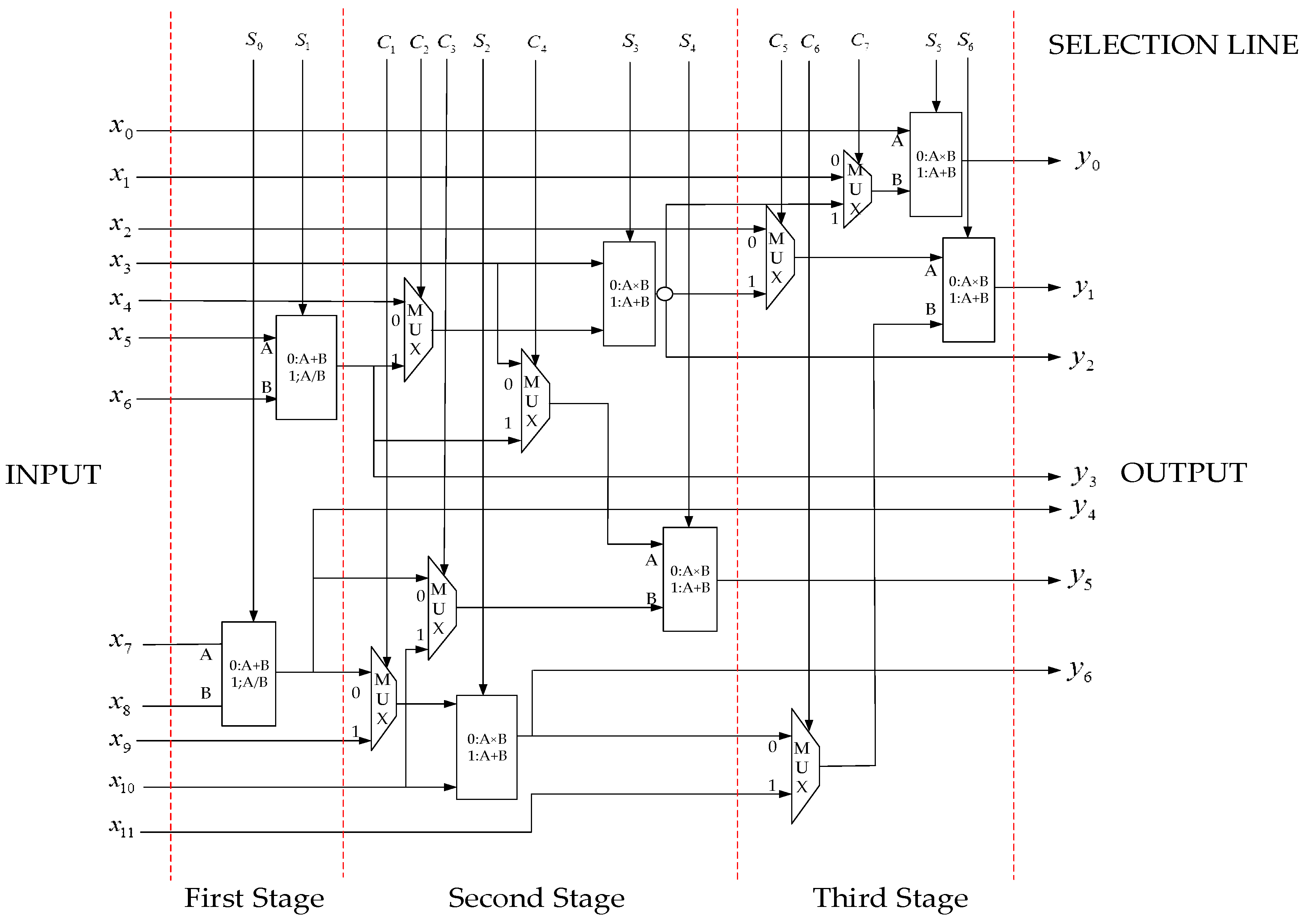
3. The Method of Multivalued Coefficients Pre-Storage

3.1. Time-Varying Conductance

In order to carry out various switching operations and fault handlings in the substation simulation system, the simulation object includes not only circuit breakers, isolation switches, and grounding switches, but also a variety of disconnection faults and short circuit faults. The on or off state of the switch and the occurrence and disappearance of the fault is described by the two-valued conductance model. The value of two-valued conductance will change due to manual operations or the actions of digital relay protection device, so they are regarded as time-varying conductance. To ensure the accuracy of the simulation calculation, it is stipulated that the time-varying conductance only change at the simulation time node. In the electromagnetic transient simulation, in addition to the two-valued conductance related with the switchgears and the faults, there are multivalued conductance related with the ground resistances and loads.
For the time-varying conductance set by the industrial control machine, FRTDS changes the value according to information sent by the industrial control machine. For the time-varying conductance related with the switchgears, FRTDS records their state in logic variable S, and then the conductance can be calculated as:
G = SGon + (1 − S)Goff
If the industrial control machine gets the state information from the switchgears and then send the conductance values to FRTDS, the calculation of the conductance values by FRTDS can be avoid. However, it makes the switch action with a delay, and the simulation results are different from the real situation.

3.2. Nonlinear Inductance

The voltage equation of the transformer excitation branch and the magnetization curve gained by piecewise linearization are shown as Equations (4) and (5), where k is the number of the section, Lk is the equivalent inductance of section k, and Ψ0k is the remaining flux linkage of the section k:
u L ( t ) = d ψ L ( t ) / d t
ψ L ( t ) = L k i L ( t ) + ψ 0 k
The implicit trapezoidal method is used to Equation (4) and obtain:
ψ L ( t ) = Δ t 2 u L ( t ) + Δ t 2 u L ( t Δ t ) + ψ L ( t Δ t )
The Equation (5) is substituted into Equation (6), where Gk = Δt/(2Lk) is the equivalent conductance of section k, ILk = −Ψ0k/Lk is the remaining current of section k:
i L ( t ) = G k u L ( t ) + G k u L ( t Δ t ) + ψ L ( t Δ t ) L k + I k
The Lk, Gk, Ik in Equation (7) is related with ΨL(t). In the simulation process, which segment ΨL(t) is located should be determined, and then save the result in the logical variable Dk. By multiplying the multivalued coefficients and the logical variable to obtain the real value, such as the equivalent conductance of the transformer excitation branch:
G = k D k G k

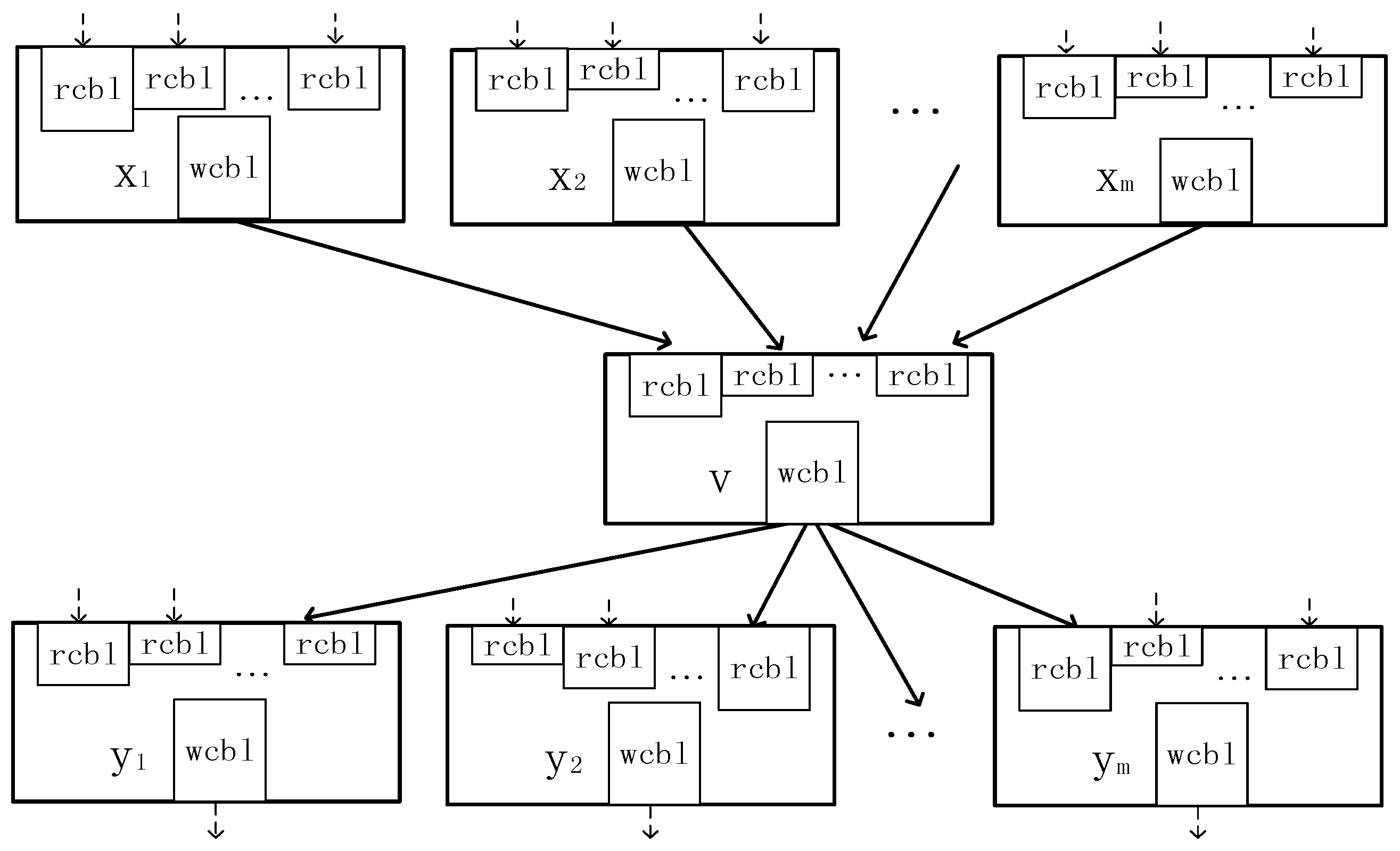
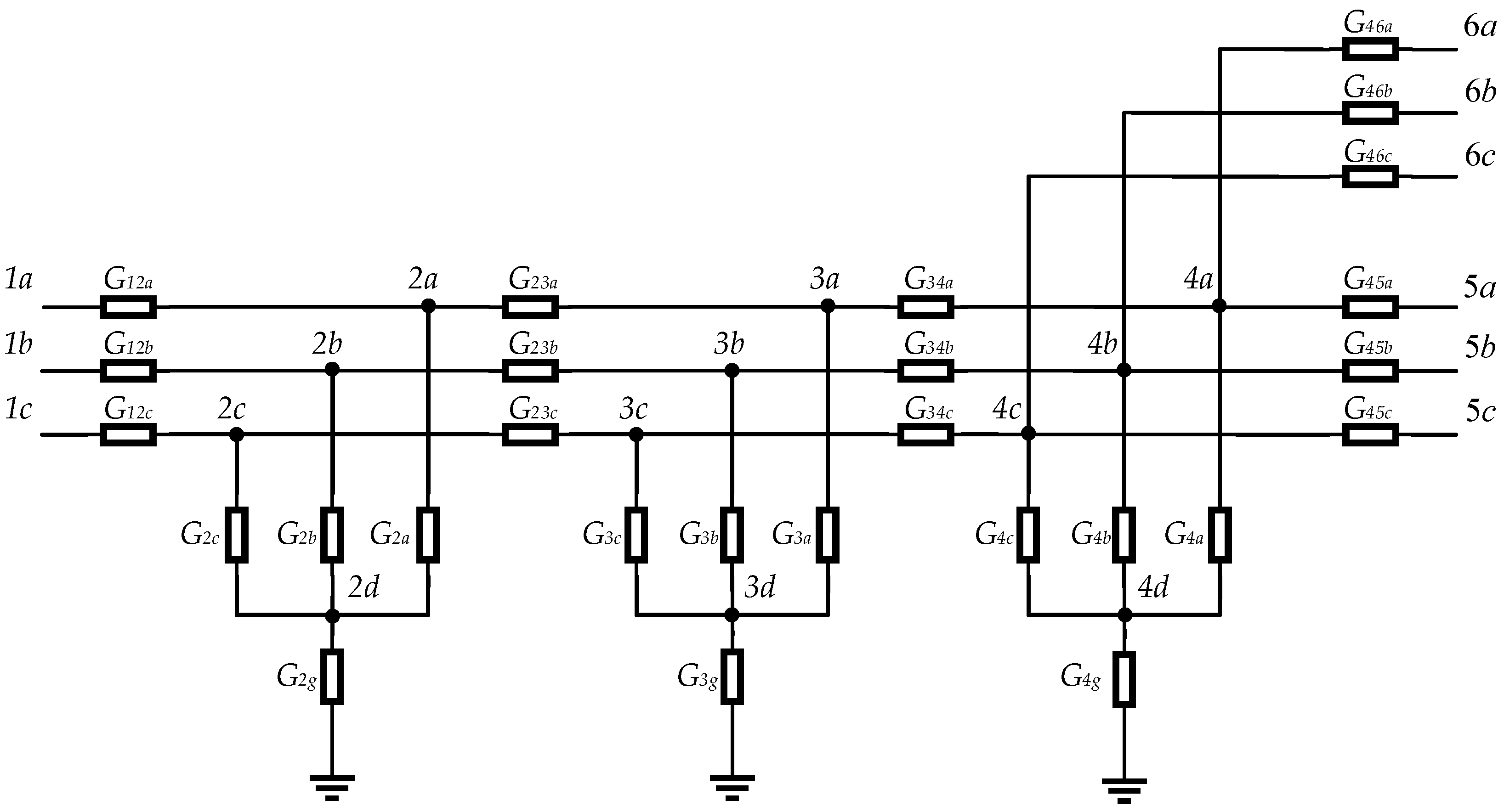
3.3. The Local Equivalence of the Network

In the electromagnetic transient simulation of the substation, most of the branch conductance is time-varying conductance or non-linear conductance. Therefore, most of the elements of the admittance matrix in the nodal analysis method need to be calculated once for each simulation step, and some non-linear elements need to be calculated several times. If the possible values of the admittance matrix elements are saved in advance, the calculation time can be shortened by looking up the table to obtain the current value. However, there are thousands of simulation nodes in the large-scale substation simulation system, and even using the admittance matrix element pre-storage method is difficult to solve the problem of long simulation time. In order to reduce the dimension of the admittance matrix effectively, the substation inlet-outlet line units are local equivalent in this paper and the equivalent conductance and voltage coefficients are pre-stored.
There are isolation switches, circuit breakers, and current transformers in an inlet-outlet line unit line of the substation. Figure 4 shows the equivalent circuit of the inlet-outlet line unit that is connected with the double bus. Where G12, G45, G46 are the equivalent conductance of the isolation switches, G23 is the equivalent conductance of the circuit breakers, G34 is the equivalent conductance of the current transformers (constant to be 108 S), G2, G3, G4 are the equivalent conductance of the short circuit faults. Except that G2g, G3g, G4g are the multivalued conductance, the rest are two-valued conductance. If the network equivalent is performed with node 1, 5, 6, the value of G2g, G3g, G4g should be limited, otherwise the number of the multivalued coefficients will be too many. In order to set the value of G2g, G3g, G4g arbitrarily, the network equivalent is performed with node 1, 5, 6, 2d, 3d, 4d. Now, there are three independent subnetworks, (1) 1a, 5a, 6a, 2d, 3d, 4d (2) 1b, 5b, 6b, 2d, 3d, 4d (3) 1c, 5c, 6c, 2d, 3d, 4d. The structure of these subnetworks is same, and each subnetwork has seven two-valued conductance, the number of equivalent conductance can reach 128.
When the nodal analysis method is adopted, in order to maintain the connectivity of the network topology, the value of the two-valued conductance is usually defined as 10−8/108 S. Because the subnetworks only contain conductance, the voltage of the internal node can be assumed zero when this internal node cannot reach any boundary node. Thus, the entire two-valued conductance in Figure 4 can be defined as 0/108 S.
When the two boundary nodes are not connected, the equivalent conductance between them must be zero. At the same time, the non-zero conductance have the same value (108 S) and the network symmetry, which leads to the higher probability that the equivalent conductance has the same value. For example, if one of G12a, G23a, G45a is zero, then the value of the equivalent conductance G1a,5a between node 1a and 5a is zero. No matter of G4a or G46a is 0 S or 108 S, the value of G1a,5a is the same. The number of the equivalent conductance is given in Table 1, which is less than 16 in average.
Digital relay protection devices need to know the current of the current transformer, and switchgears from the “on” to “off” when the current is crossing zero. It is necessary to calculate all of the branch currents of the inlet-outlet line unit. The voltage of the internal nodes can be calculated first and then calculate the internal branch currents. The internal node voltage is calculated as Equation (9), Ki,j is the voltage coefficients, Ui is the voltage of the internal node, and Uj is the voltage of the boundary node.
U i = j K i , j U j
The voltage coefficients have similar characteristics to the equivalent conductance and the number of their values are not many. The number of the voltage coefficients is given in Table 2, which is less than 20 in average.

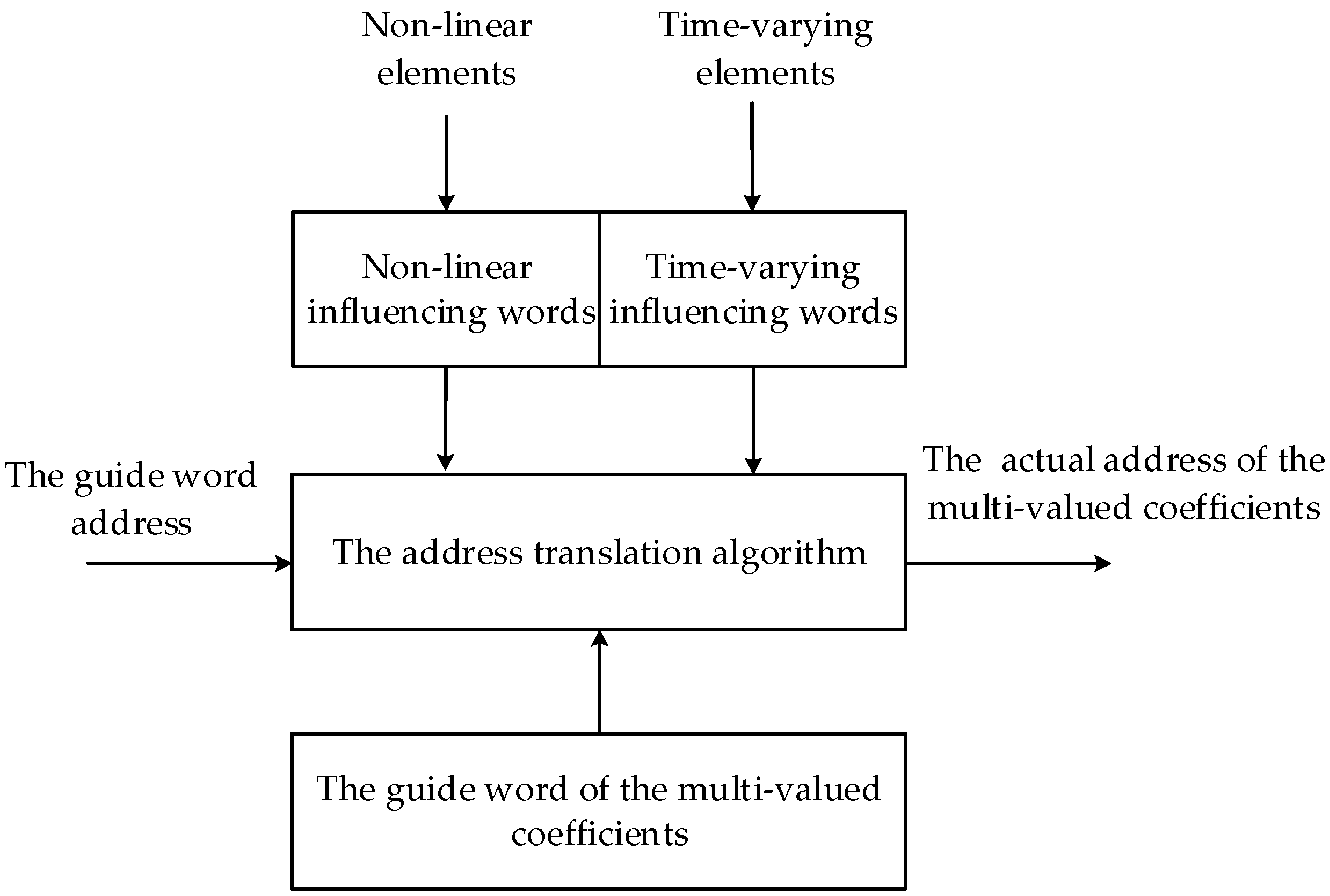
3.4. The Query of the Multivalued Coefficients

The multivalued coefficients is the simulation variable has a variety of definite values in the simulation, such as the equivalent conductance and voltage coefficients mentioned above. In order to determine the current value of the multivalued coefficients, a dedicated hardware circuit is used to query the address of the multivalued coefficients, as shown in Figure 5.
This addressing process is completed in the order stream and does not occupy the PEs computational resources. The influencing words show the factors that affect the value of the multivalued coefficients. Each of the influencing words has 16 bits and every bit represents a factor, while the undefined bit is filled with 0. The time-varying influencing words are controlled by the industrial control machine or the external hardware device. However, the non-linear influencing words are controlled by the microprocessor core. One multivalued coefficient may involve both the time-varying influencing words and the non-linear influencing words, and they are merged into the total influencing words by the “connection” operation.
The address translation algorithm of the multivalued coefficients calculates the actual address according to the given influencing words. Varieties of commonly used hardware circuits for address translation algorithm can be designed according to the characteristics of the influencing words. These circuits are designed in accordance with the concept of refactoring and can be solidified in the FPGA.
In Equation (7), the values of the Lk can be sequentially stored in the order of L0, L1, L2,…, Ln. The bits of the nonlinear influencing word can be determined by comparing the current magnetic flux ΨL(t) with the segmented magnetic flux Ψk. If ΨL(t) is greater than Ψk, then the corresponding bit is set to 1, otherwise it is 0. The address transformation algorithm of the Lk is:
m = n + e
where n represents the base address of Lk, e represents the number of 1 in the nonlinear influencing word.
The time-varying influencing word of G1a,5a is 7 bits, which are represented by the state of G12a, G23a, G45a, G46a, G2a, G3a, and G4a, respectively. The address transformation algorithm of the G1a,5a is:
m = n + a((b + 1)(c + 1) + 1)
where n represents the base address of G1a,5a. When all of the states of G12a, G23a, G45a are 1, a = 1, otherwise a = 0. When G2a, G3a are 00, 01, 10, 11, b is 0, 1, 2, 3. c represents the number of 1 in G4a and G46a.
Due to the symmetry of the network, the address transformation algorithm of G1a,4d, G1a,6a, G2a,4d, G2d,5a, and G2d,6a are the same, with G1a,5a, but the position of G12a, G23a, G45a, G46a, G2a, G3a, and G4a in the time-varying influencing words are different.
In order to ensure that the multivalued coefficients address query circuit is working normally, the time-varying influencing words address, the non-linear influencing words address, the serial number of the address transformation algorithm, and the base address of the multivalued coefficients are described by a variable called the guide word. In the orders, the address of the multivalued coefficients is replaced by the address of the guide word.
Since the address transformation algorithm is not carried out in the PE, the simulation script cannot show that the multivalued coefficients dependency on the nonlinear influencing words. In order to solve this problem, a virtual multivalued coefficients calculation task is introduced in the simulation script. The task execution time is from the acquisition of the influencing words to the order address sent to the read controller.

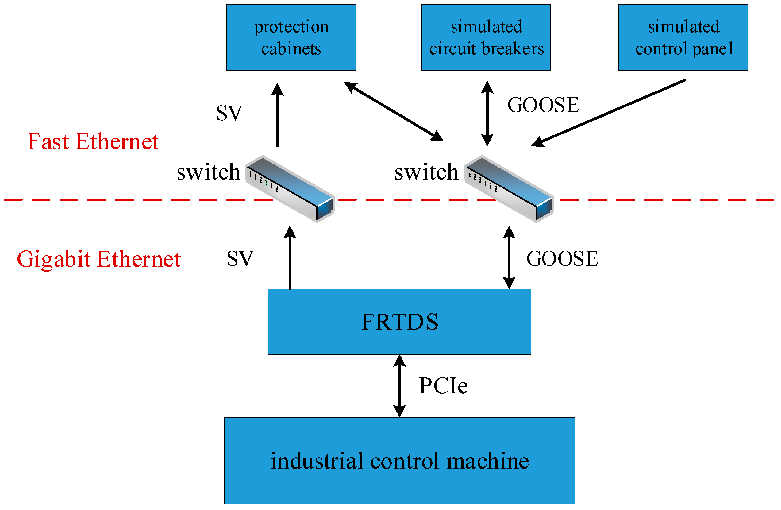
4. Network Communication of Process Layer

4.1. Communication Interface

Sampled value (SV) and Generic object oriented substation event (GOOSE) packets are two kinds of communication services in the smart substation process layer, which use the Ethernet frame format with the priority tag. The application protocol data unit (APDU) frame data is encoded according to the basic coding rules of ASN.1, as shown in Figure 6. In the middle of this figure is the Ethernet frame, the left and the right are the detailed APDU structure of SV and GOOSE.
Gigabit Ethernet interface is implemented on the FPGA development board for sending SV packets and receiving GOOSE packets, which consists of four parts: SFP module, PSC/PMA layer IP core, MAC layer IP core, send/receive FIFO. The send/receive FIFO is used to address the different working clock between the MAC layer and the FRTDS. The data written to the send FIFO or read from the receive FIFO does not include the preamble of the Ethernet frame, the start of frame delimiter and the last check codes, reducing burden of the SV formation and the GOOSE resolution.

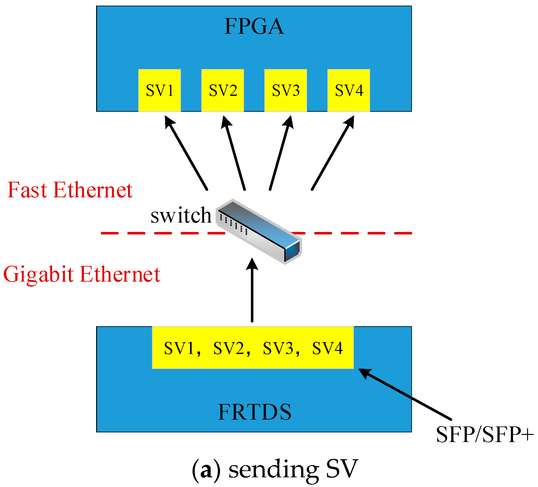
4.2. Formation of SV Packet

The voltage and current values in the data outflow area of the FRTDS need to be sent to the digital relay protection device in the form of SV packet. In the case where the APPID is determined, the format of the SV packet and the location of the fields are determined. The contents of the SV packets with the same APPID are the same except for the smpCnt and dataSet fields. The smpCnt is the sampled counter, which automatically adds one when a packet is sent. The dataSet is the sampled channel. The first four bytes of each sampled channel are the voltage and current sampled value. The last 4 bytes are the quality of the sampled value. The value of smpCnt can be set by a counter circuit. However, the value of dataSet is not so easy to determine because the sampled period and the simulation step size may not an integer multiple, that is, the sampled value is between the two simulation time nodes. In order to ensure the accuracy of the sampled value, the voltage and current sampled values are determined by linear extrapolation using the sampled values of the two simulation time nodes before the current sampled time.
Since the Ethernet communication interface is limited and more than one merging unit needs to be simulated. The SV packets of these merging units are usually sent by an Ethernet communication interface. In order to ensure that the digital relay protection devices can receive these packets at the same time, all of the SV packets are organized and then sent.
All of the SV packet templates are saved in the sending data preparation area according to the sequence of SV packet length + SV packet contents, and zero is added at the end. It can reduce the need for data storage space. When the contents of the sending data preparation area are transferred to the sending FIFO, all of the SV packets are sent one by one according to the length of each packet. When the packets length is zero, the sending is ended.
The correspondence between the datSet in the SV packets and the data outflow area is related to the simulation object. A template modification service module based on orders is established, which makes the modification of the SV packet templates have a certain degree of versatility. There are three types of the orders. Type1—assigning the value of the counter circuit to smpCnt, type2—assigning the data of outflow area to the datSet, and type3—ending the orders. As with the modification of the multivalued coefficients and the calculation orders, the SV packet templates and its orders are configured to the corresponding data memory before the simulation starts.

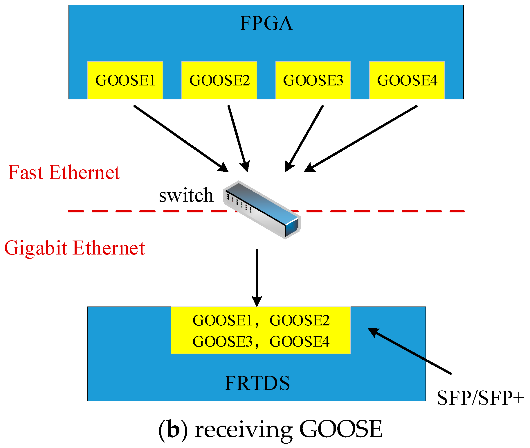
4.3. Resolution of GOOSE Packet
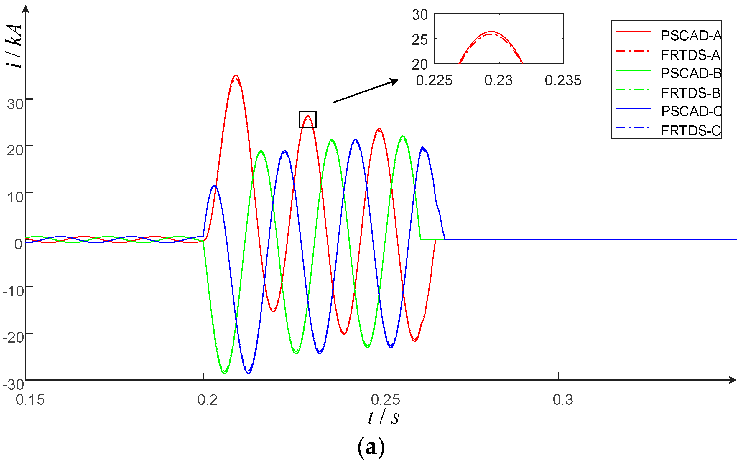
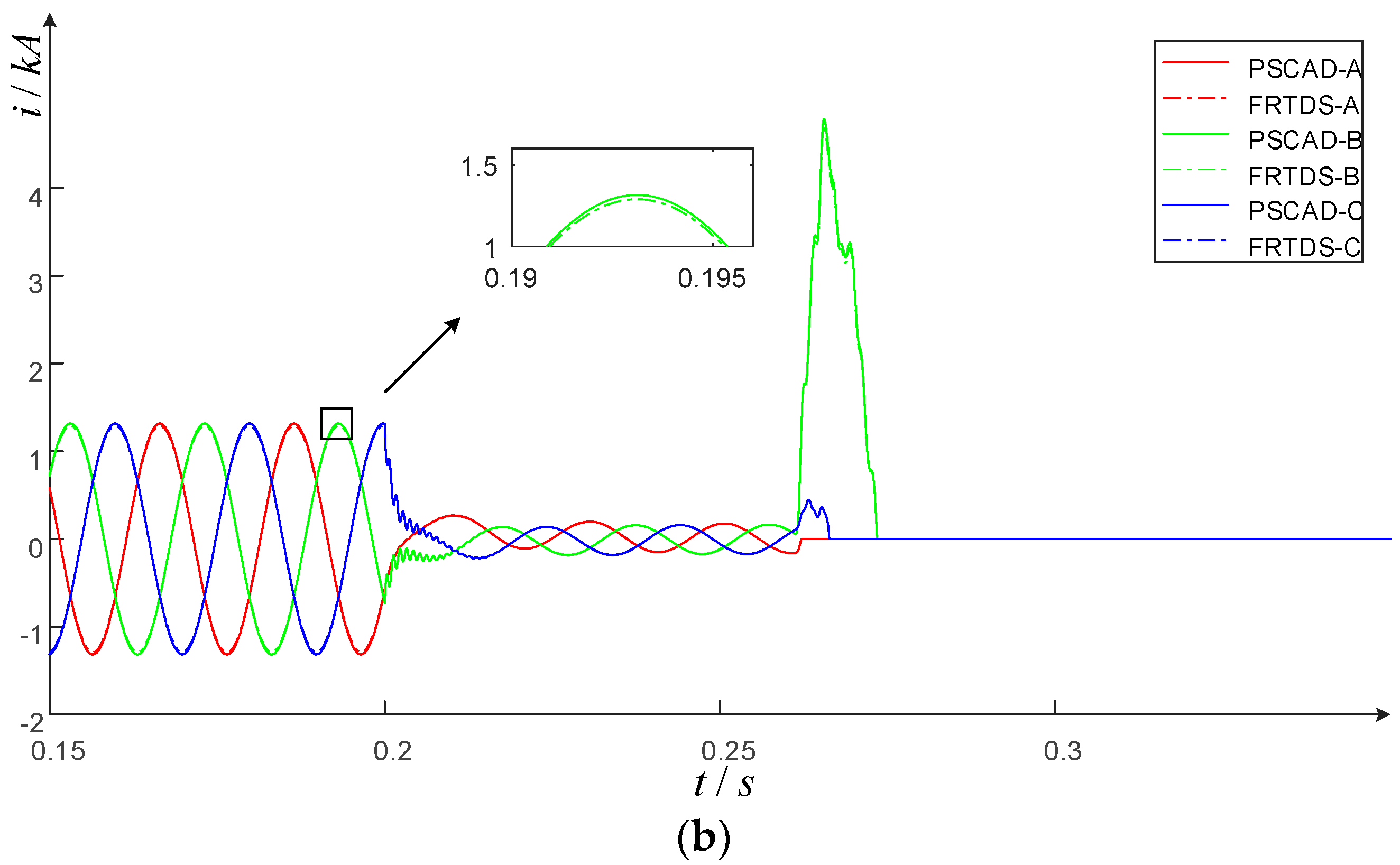
The state information of the smart switch is sent to FRTDS as a GOOSE packet. In the case of APPID determination, the location of the allData field is fixed in the packet. Since the data processing area stores the data from the receive FIFO in a circular manner, the location of the allData in the data processing area is different even if the APPID of the GOOSE packets are the same. Therefore, the first address of each packet is saved in a FIFO queue, providing information for the subsequent search for allData locations, after receiving the full GOOSE packets.
A state extraction service module based on orders is created, which is similar to the template modification service module of SV packet. The orders gives the switch serial number and its state position in the GOOSE packet. The allData field position of the GOOSE packets with the same APPID is fixed relative to the packet first address, so that the processing orders can be organized for different APPID. A comparison table of the APPID and the processing orders are designed to find from the APPID to the corresponding orders. In this way, the state extraction service module gets the APPID according to the first address of the GOOSE packet, and the orders are obtained by the APPID. Then, the allData position in the receiving data processing area can be got. The switch serial number specified in the orders and the switch state extracted from allData are saved to the switch state FIFO queue.
In general, a switch state has an effect on multiple multivalued coefficients. In this paper, the entire time-varying influence word addresses that are associated with the switch state and their position are stored in the state associate word. Since the switch state changing from “on” to “off” occur when the branch current is crossing zero, the address of the voltage across the branch is also recorded in this state associate word. Therefore, FRTDS can change the time-varying influence words of the relevant multivalued coefficients according to the data in the switch state FIFO queue.
In addition, the disconnection fault and short-circuit fault information set on the industrial control machine are delivered to the fault state FIFO queue via the PCIe interface. The method of changing the relevant multivalued coefficients by the fault state FIFO queue is the same as the switch state FIFO queue.

5. Case Study

The Xilinx Virtex-7 VC709 FPGA (Xilinx Company, San Jose, CA, USA) is adopted to build FRTDS. There are eight microprocessor cores, four Gigabit Ethernet interfaces, and one peripheral component interface express (PCIe) interface. One Gigabit Ethernet interface is used for receiving GOOSE packets and the other three Gigabit Ethernet interfaces are used for sending SV packets. The PCIe interface is used for the communication with the industrial control machine.
The smart substation real-time hardware-in-the-loop simulation platform consists of five parts: FRTDS, the industrial control machine, protection cabinets, simulated circuit breakers, and simulated control panel. The industrial control machine is responsible for the fault settings, load settings, mistake-operation judgment, substation operation monitoring, and so on. Protection cabinets, simulated circuit breakers and simulated control panel are the hardware devices, which are connected with FRTDS by the process layer network. The SV and GOOSE are networking, respectively, and the switch has the Gigabit Ethernet interfaces and Fast Ethernet interfaces. The Gigabit Ethernet interfaces are used to connect with FRTDS, while the Fast Ethernet interfaces are used to connect with protection cabinets, simulated circuit breakers and simulated control panel. The overall structure of the real-time simulation platform is shown in Figure 7.
A typical 220 kV smart substation shown as Figure 8 is used to verify the simulation calculating capability and the hardware-in-the-loop ability of the FRTDS simulation platform.

5.1. Simulation Calculating Capacity

The electromagnetic transient simulation script of the smart substation, as shown as Figure 8, is designed according to the nodal analysis method. In order to show the advantages of multivalued coefficient addressing circuit, there are three methods to obtain the actual value of the multivalued coefficient. Method 1: the actual value of the multivalued coefficient is calculated by PE in the way of multiplying the multiple values and logical variables. Method 2: the multivalued coefficient addressing process is performed by PE calculation. Method 3: the multivalued coefficient addressing process is performed by the specific multivalued coefficients address query circuit. The simulation time of these methods are shown in Table 3. From the table, we can see that the use of multivalued coefficients address query circuit can effectively reduce the simulation time, because the addressing process is completed in the instruction stream and the calculation time of the PE is not increased.
In order to verify the effectiveness of the equivalent method of the inlet- outlet line unit, it is applied to the smart substation simulation. Table 4 shows the changes of simulation node, multivalued coefficients storage, simulation time before and after this equivalent method. From the table we can see the equivalent method requires a little increase in data storage but can reduce the simulation time significantly. Therefore, this method can expand the simulation scale of the smart substation effectively.

5.2. Haredware-in-the-Loop Ability

There are fourteen sets of circuit breakers in this smart substation, each circuit breakers has the corresponding relay protection device. The main and backup protection of 220 kV transmission lines are pilot protection and distance protection. The main and backup protection of 110 kV transmission lines are distance protection and zero sequence current protection. The main and backup protection of transformer are pilot protection and overcurrent protection. The protection of 220 kV and 110 kV bus are pilot protection. In the actual substation, fourteen relay protection devices receive the SV packets from twelve merging units. Taking the cost of real-time simulation platform into account, the function of the merging units are simulated by FRTDS and the circuit breaker function is realized by the simulated circuit breaker.
As the transmission of twelve SV packets needs to be completed by three Gigabit Ethernet interfaces, each interface needs to transmit four packets in serial. In order to test the communication delay of sending SV packets, four Fast Ethernet interfaces of another FPGA development board are used to receive four SV packets from one Gigabit Ethernet interface of FRTDS, as shown in Figure 9a. The test result shows that the time interval between the first packet and the last packet received by FPGA is less than 12 μs. Therefore, it is feasible to simulate four SV packets with one Gigabit Ethernet interface.
The situation that more than four circuit breakers action at the same time is not much. In order to test the communication delay of receiving GOOSE packets, four Fast Ethernet interfaces of another FPGA development board are used to simulate the sending four GOOSE packets at the same time, as shown in Figure 9b. The time interval between the first packet and the last packet received by FRTDS is less than 10 μs, which is only one-fifth of the simulation step of 50 μs. Therefore, the real situation result is hardly amplified.
In the double-bus running-parallel mode, the four incoming lines are connected with the 220 kV bus I, four outgoing lines are connected with the 110 kV bus I. No. 1 and No. 2 transformer are connected with the 220 kV bus I and 110 kV bus I. The FRTDS is connected with industrial control machine, protection cabinets, simulated circuit breaker, and simulated control panel. The industrial control machine sends information that the high-voltage side of the No. 2 transformer occurs three-phase non-metallic short-circuit fault to the FRTDS, the grounding resistance is 1 Ω. The simulation with the same circuit parameters, fault type, and breaker trip time is also carried on the power systems computer aided design (PSCAD), and the results of the three-phase current of the 213, 113 circuit breaker are shown in Figure 10a,b to take a comparison with FRTDS.
It can be seen from figures that after the occurrence of three-phase short-circuit fault in 0.2 s, the three-phase current in the high-voltage side flows from the 220 kV bus I to the short-circuit point, and its amplitude rises sharply. The three-phase current in the low-voltage side flows from the 110 kV bus I to the short-circuit point, and its amplitude decreases. After 0.06 s, the circuit breakers on the two sides of the No. 2 transformer are off. The circuit breaker is off at the current zero point and the zero sequence current path exists. Therefore, the action time of the circuit breakers are different, followed by 213 B-phase, 113 A-phase 213 A-phase, 113 C-phase, 213 C-phase, and 113 B-phase. After 213 B-phase is off, the B-phase voltage of 110 kV and 220 kV bus increasing cause the increasing of the B-phase current of the circuit breaker 113. The error between the FRTDS and PSCAD simulation waveform is within 3%, it has a higher simulation accuracy.

6. Conclusions

(1)
The proposed inlet-outlet line unit described by the 0/108 S conductance has disconnection between nodes and network symmetry. The number of equivalent conductance and voltage coefficients is much less than that described by the 10−8/108 S conductance. This allows for FRTDS to perform electromagnetic transient simulations with the equivalent model of inlet-outlet line unit and significantly reduce the simulation calculations to expand the scale.
(2)
The address transformation algorithm is designed according to the characteristics of the influencing words, which is associated with the multivalued coefficients guide word, so that the multivalued coefficients address query circuit has good expansibility. At the same time, this circuit works independently of the PE, which effectively reduces the computational burden of the PE.
(3)
By using the field fixed location in the same APPID packet and orders design concept. The development of the template modification service module and the state extraction service module to solve the uncertainty of SV and GOOSE packet structure, which makes FRTDS easy for smart substation hardware-in-loop real-time simulation platform.

Acknowledgments

The work presented was supported by the National Natural Science Foundation of China (No. 51477114).

Author Contributions

Bingda Zhang put forward the research direction, organized the research activities, provided theory guidance, and completed the revision of the article. Yanjie Wu completed the principle analysis and the method design, performed the simulation, drafted the article. Zhao Jin and Yang Wang analyzed the simulation results. Valuable comments on the first draft were received from Bingda Zhang. All four were involved in revising the article.

Conflicts of Interest

The authors declare no conflict of interest.

References

  1. Jing, S.; Huang, Q.; Wu, J.; Zhen, W. A Novel Whole-View Test Approach for Onsite Commissioning in Smart Substation. IEEE Trans. Power Deliv. 2013, 28, 1715–1722. [Google Scholar] [CrossRef]
  2. Huang, Q.; Jing, S.; Li, J.; Huang, Q.; Jing, S.; Cai, D.; Wu, J.; Zhen, W. Smart Substation: State of the Art and Future Development. IEEE Trans. Power Deliv. 2017, 32, 1098–1105. [Google Scholar] [CrossRef]
  3. Song, Q.; Sheng, W.; Kou, L.; Zhao, D.; Wu, Z.; Fang, H.; Zhao, X. Smart substation integration technology and its application in distribution power grid. CSEE J. Power Energy Syst. 2016, 2, 31–36. [Google Scholar] [CrossRef]
  4. He, X.; Jiang, X.; Zhang, P.; Gao, X. Availability Analysis of Smart Substation Protection System Considering Maintenance Strategies. Power Syst. Technol. 2015, 39, 1121–1128. [Google Scholar] [CrossRef]
  5. Liu, H.; Hu, J.; Li, F.; Qi, Z. Design and Implementation of Simulation Test System for Substation Automation. Autom. Electr. Power Syst. 2012, 36, 109–112. [Google Scholar] [CrossRef]
  6. Peng, F.; Gao, H.; Liu, Y.; Kong, F. Practical test technology and solution based on RTDS-GTNET for protective equipment in smart substation. Electr. Power Autom. Equip. 2016, 36, 160–165. [Google Scholar] [CrossRef]
  7. Meng, H.; Liang, X.; Liu, Y.; Zhao, Y. Research on Closed Loop Real Time Simulation System of Relay Protection for Digital Substation. Power Syst. Technol. 2010, 34, 198–203. [Google Scholar] [CrossRef]
  8. Razzaghi, R.; Mitjans, M.; Rachidi, F.; Paolone, M. An automated FPGA real-time simulator for power electronics and power systems electromagnetic transient applications. Electr. Power Syst. Res. 2016, 141, 147–156. [Google Scholar] [CrossRef]
  9. Ouldbachir, T.; Blanchette, H.; Al-Haddad, K. A Network Tearing Technique for FPGA-Based Real-Time Simulation of Power Converters. IEEE Trans. Ind. Electr. 2015, 62, 3409–3418. [Google Scholar] [CrossRef]
  10. Chen, Y.; Dinavahi, V. Hardware Emulation Building Blocks for Real-Time Simulation of Large-Scale Power Grids. IEEE Trans. Ind. Inform. 2013, 10, 373–381. [Google Scholar] [CrossRef]
  11. Wang, C.; Ding, C.; Li, P.; Yu, H. Real-time Transient Simulation for Distribution Systems Based on FPGA, Part I: Module Realization. Proc. CSEE 2014, 34, 161–167. [Google Scholar] [CrossRef]
  12. Wang, C.; Ding, C.; Li, P.; Yu, H. Real-time Transient Simulation for Distribution Systems Based on FPGA, Part II: System Architecture and Algorithm Verification. Proc. CSEE 2014, 34, 628–634. [Google Scholar] [CrossRef]
  13. Chen, Y.; Dinavahi, V. Multi-FPGA digital hardware design for detailed large-scale real-time electromagnetic transient simulation of power systems. IET Gener. Trans. Distrib. 2013, 7, 451–463. [Google Scholar] [CrossRef]
  14. Zhang, B.; Zhao, D.; Jin, Z.; Wu, Y. Multivalued Coefficient Pre-storage and Block Parallel Method for Real-Time Simulation of Micro-grid on FRTDS. Energies 2017, 10, 1248. [Google Scholar] [CrossRef]
  15. Chen, Y.; Dinavahi, V. FPGA-Based Real-Time EMTP. IEEE Trans. Power Deliv. 2009, 24, 892–902. [Google Scholar] [CrossRef]
Figure 1. Arithmetic expression circuit.
Energies 10 01795 g001
Figure 2. The overall structure of real-time digital solver based on FPGA (FRTDS).
Energies 10 01795 g002
Figure 3. Directed acyclic graph (DAG) considering the queue length of the controllers.
Energies 10 01795 g003
Figure 4. The inlet-outlet line unit connected with the double bus.
Energies 10 01795 g004
Figure 5. The address query circuit of the multivalued coefficients.
Energies 10 01795 g005
Figure 6. The frame structure of generic object oriented substation event (GOOSE) and sampled value (SV).
Energies 10 01795 g006
Figure 7. The overall structure of the real-time simulation platform.
Energies 10 01795 g007
Figure 8. Main wiring diagram of 220 kV smart substation.
Energies 10 01795 g008
Figure 9. Communication test scheme. (a) Sending SV; (b) receiving GOOSE.
Energies 10 01795 g009aEnergies 10 01795 g009b
Figure 10. Three-phase current of breaker: (a) 213; (b) 113.
Energies 10 01795 g010aEnergies 10 01795 g010b
Table 1. The number of equivalent conductance.
Equivalent ConductanceQuantityEquivalent ConductanceQuantity
G1a,2d17G3d,6a13
G1a,3d9G4d,5a15
G2a,3d9G4d,6a15
G1a,4d13G5a,6a15
G1a,5a13G1a,1a19
G1a,6a13G2a,2d19
G2d,4d13G3d,3d17
G2d,5a13G4d,4d25
G2d,6a13G5a,5a25
G3d,4d13G6a,6a25
G2d,5a13--
Table 2. The number of voltage coefficients.
Voltage CoefficientsQuantityVoltage CoefficientsQuantity
K2a,1a19K3a,4d25
K2a,2d19K3a,5a25
K2a,3d13K3a,6a25
K2a,4d19K4a,1a17
K2a,5a19K4a,2d17
K2a,6a19K4a,3d17
K3a,1a17K4a,4d25
K3a,2d17K4a,5a25
K3a,3d17K4a,6a25
Table 3. Comparison of simulation time for three methods.
MethodSimulation Time (μs)
156.145
253.465
348.115
Table 4. Comparison of using the inlet and outlet unit equivalent.
MethodSimulation NodeThe Storage of Multivalued Coefficients (kb)Simulation Time (μs)
Before35276848.115
After22697537.465

