The Thermoelectric Analysis of Different Heat Flux Conduction Materials for Power Generation Board


Power Electronics Research Center, Department of Electrical Engineering, The Hong Kong Polytechnic University, 11, Hong Chong Road, Kowloon, Hong Kong
*
Author to whom correspondence should be addressed.
Energies 2017, 10(11), 1781; https://doi.org/10.3390/en10111781
Submission received: 10 October 2017
/
Revised: 24 October 2017
/
Accepted: 31 October 2017
/
Published: 5 November 2017
(This article belongs to the Section F: Electrical Engineering)
Abstract
:The development of the thermoelectric (TE) power generation is rapid, and the applications have extensively been studied. The principle is based on the Seebeck effect, in which the temperature difference between hot and cold sides of the TE material converts to electrical energy. In this paper, a design is proposed to convert the thermal energy between indoor and outdoor of a board to electrical energy by the thermoelectric generator (TEG). Furthermore, the electrical energy generated is charged to supercapacitors as a battery or a power supply to the loads (e.g., lights) of the house. Besides the experimental work, a thermal model and an electrical model of the TEG have been proposed. To study the power generation performance in terms of materials, the simulation of the conversion efficiency of the TE board using materials with different thermal conductance have also been conducted. It was found that, using graphene as the thermally conductive material, the conversion efficiency was enhanced by 1.6% and 1.7%, when the temperature difference was 15 °C and 40 °C, respectively.
1. Introduction
With the increasing prominence of environmental and energy issues, and the challenges of fossil energy losses and environment pollution, renewable energy, such as solar, wind and wave [1], has become more and more important to human. The thermoelectric generation (TEG) technology, as one of the renewable generation methods, has widely been used in various industries and situations. Especially, the waste heat flux has usually been ignored and abandoned. If waste heat flux could be utilized effectively by the TEG technology as the thermal energy source, it would break the routine of energy utilization, and create a new sight of energy storage.
In recently years, with improving the efficiency of TEG energy conversion, TEGs have attracted attention for applications with solar energy, vehicles and human diagnosis devices. Firstly, solar energy as a green and cost-effective renewable energy has been utilized in recent years. There is an energy harvesting system that not only harvests both solar and thermal energies with a solar tracking system, but also converts the thermal energy to electrical energy by the TEG, thus the proposed system has increased the conversion efficiency to 38.65% [2,3,4,5]. Secondly, there is about 40–70% thermal energy loss through the exhaust system in the vehicle with a gasoline engine. To reduce the fuel used and increase the efficiency of the vehicle, the waste heat flux has been transmitted to the TEG’s hot side, which is installed at the surface of the exhaust system [6,7,8]. Thirdly, the applications of the intelligent wearable technology have been developed rapidly; it especially plays a significant role in the healthcare field. A flexible supercapacitor is reported to store the electrical energy generated from the heat flux energy of the human body through the TEG, which not only monitors human health, but also supplies the power for other wearable devices. That is a breakthrough for combining wearable devices and renewable energy to form a flexible power generation system [9].
Unfortunately, compared to the thermal power generation, the efficiency of TEG is much lower. Thus, it has been proposed to be used only in a few applications where the thermal energy is abandoned or only low power is demanded [10,11]. Furthermore, since the temperature difference cannot be controlled in the working environment, the output voltage also changes accordingly. Therefore, a voltage regulator circuit must be designed in the TEG system. In addition, if the temperature difference takes a long time to produce, then the power generation performance and efficiency will also be affected greatly [12,13,14,15]. These studies mentioned above failed to give the exact mathematic model for this type of power generation system and the efficiency of the TEG system has not been investigated deeply. In this paper, these untapped works have been reported and discussed. It paves a fundamental venue for the development of TEG systems.
It is known that the board is the core part of house. During summer and winter, there should be a temperature difference between indoor and outdoor. That temperature difference should be larger in relatively hot or cold areas. It should be beneficial if such temperature difference could be utilized for electricity generation based on the TEG technology. Thus, the present purpose is to verify the idea of TE board by doing experiments and simulations. In the prototype system, the electricity generated from the TEGs charged supercapacitors or was used to supply lights of the building. Besides, as the conversion efficiency of TE board should be related to the thermal conductance of the material, this has also been studied using materials with different thermal conductance. Although the experimental result shows that the conversion efficiency has only been slightly improved with using the graphene, the thermal model has been verified for the application related to the concept of TE board power generation system.
2. Theory Analysis of TEG
2.1. Thermal Model of TE Board
In a basic module of a TEG, there are many couples of n-type and p-type TE semiconductors connected electrically in series and thermally in parallel. Figure 1 shows a schematic of the fundamental unit of a TE module. In the module, the flow of heat flux drives the free electrons (e−) and holes (h+), producing the electrical power from the temperature difference (Tin − Tout) of both ends. Th and Tc are the hot and cold junction temperatures, respectively. Additionally, Kmh is the thermal conductance of the thermally conductive material, and Kw is the thermal conductance of the board [16,17]. This coefficient can be up to 5300 W/m·K for suspended grapheme [18,19]. The ordinary grapheme, in this paper, is 1200 W/m·K.
In steady state, with constant material parameters, the equation can be written as:
where Qp.n is the heat flux flow between n-type and p-type legs, Sp,n represents the cross-sectional area of the n-type and p-type legs, and dx is a length. Therefore, the sum of Qp and Qn has been established for the heat flux flow Q of a TE module.
Analyzing the relationship between the temperature difference and the heat flux flow, Fourier’s heat flux conduction law is considered.
In the temperature boundary conditions,
Then, the heat flux conduction rates are:
where
According to the Peltier theorem, αITh and αITc are two boundary points of the rate of heat flux transfer as:
and
where R is the complete internal electrical resistance, and K is the thermal conductance of TE module. The Seebeck coefficient can be obtained as:
Similar equations for the TE module have been calculated with different methods in [20], which are all focused on irreversible thermodynamics, but with different conditions. However, the property of TE board has not been explored and discussed. The improvements of output power and conversion efficiency of TE board have been proven [21].
In the TE board, the heat flux transfer approaches between indoor and outdoor are irreversible situation, and the equations can be obtained as:
As shown in Figure 1, K1 and K2 are the thermal conductance between the hot board source and the hot TEG surface and cold board source and cold TEG surface, respectively. Kw is the thermal conductance of the board, and Kmh is the thermal conductance of the thermally conductive material between the board and the hot TEG surface. Additionally, in the proposed system, the ceramic plates were used as an outer layer in TE module, so K1 is considered as a constant that is equal to K2.
According to the current TE module, the thermal conversion efficiency can be shown as:
M is represented by:
Z is the value of merit of the Bi2Te3 TE module [16]. Based on Equations (14)–(16), the conversion efficiency of the TE board can be obtained as:
where N is defined as a constant, :
The maximum output power of the TE board can be obtained as:
Consequently, with the conventional material of TE module and temperature difference, the output power P board and conversion efficiency η board could be enhanced by the increased Kmh.
2.2. Control and Electrical Model of TE Board
Figure 2 shows the control diagram of TE board power generation system. To stabilize the output voltage under different ambient temperatures, a voltage regulator circuit is required to connect in parallel with the TEG in the output port. On the other hand, the system should provide various output voltages for different loadings. Practically, a buck converter is used for the system necessarily.
The buck converter was designed to control the terminal voltage for maximizing the power output. Other power electronic topology such as switched-capacitor based converter [22,23] is also useful for TE applications because of high power density and simple control. As shown in Figure 3, the electrical characteristics depend on whether the switch is turned on or off. VB is the terminal voltage from the TE Board system, and Vo is the voltage of different loads, such as battery, supercapacitor and other equipment.
When the switch T is closed, the current of diode iD2 flows to T and then the diode D2 will be off. The inductor voltage vL is:
With the constant Vo,
Obviously, dt = ton,
The current change of inductor can be written as:
When the switch is off, the self-induced electromotive force has been attracted between the two junctions of inductor, which could conduct the diode [13,24,25,26]. Thus, the inductor supplies the energy to the load through the diode. The voltage of inductor is:
When dt = toff,
The current change during the off-state of the switch is:
Obviously, based on the flux linkage balance of the inductor:
Considering and ,
From Equation (30), with the duty ratio of buck circuit from 0 to 1, the output voltage is from 0 to , and the maxima would not exceed .
The current will not flow through the diode, when the switch is closed. However, the same current will flow across the diode, when the switch is opened. Thus, the relationship of diode current, output current io and inductor current can be expressed as follows:
According to Equations (30) and (31),
Through the above derivations, the buck converter control system for TE Board could be represented mathematically by Equations (30) and (32). If the load voltage is equal to half of the open circuit voltage, while the internal resistance of TE module is equal to load resistance, then the output power will approach to the maximum.
3. Analysis and Comparison of Thermally Conductive Materials with TEGs
3.1. Analysis of the Characteristics of TEG
Figure 4 and Figure 5 show the measured results of the output voltage and current versus different loads of TEG module (model name: SP 1848-27145, size: 40 mm (L) × 40 mm (W) × 3.6 mm (H)) in five temperature difference situations. The current sensor and voltage sensor are selected as LEM AKR 5B420L (2A) and LEM LV25-P. Their accuracies can achieve 1%. It was found that, with increasing the loads, the output current decreased while the voltage increased. The relationships between the output power and loads with different temperature difference are shown in Figure 6. The output power firstly increased to the maximum with the load resistance of 3 Ω and then decreased.
Various combinations of output voltage and current of TE modules have been adopted for achieving the uniform output power: either the higher output voltage with lower current or lower output voltage with higher current. For the case of “higher output voltage and lower current”, semiconductor pellets inside the TEG could be connected in series. However, both the internal impedance and the difficulty of manufacture of TEG would increase, and the reliability of the system will also reduce. Therefore, to obtain high conversion efficiency and reliability of the TE board power generation system, the relatively small number of large semiconductor pellets connected in series should be used.
3.2. Analysis of the Characteristics of TEG with Different Thermally Conductive Materials
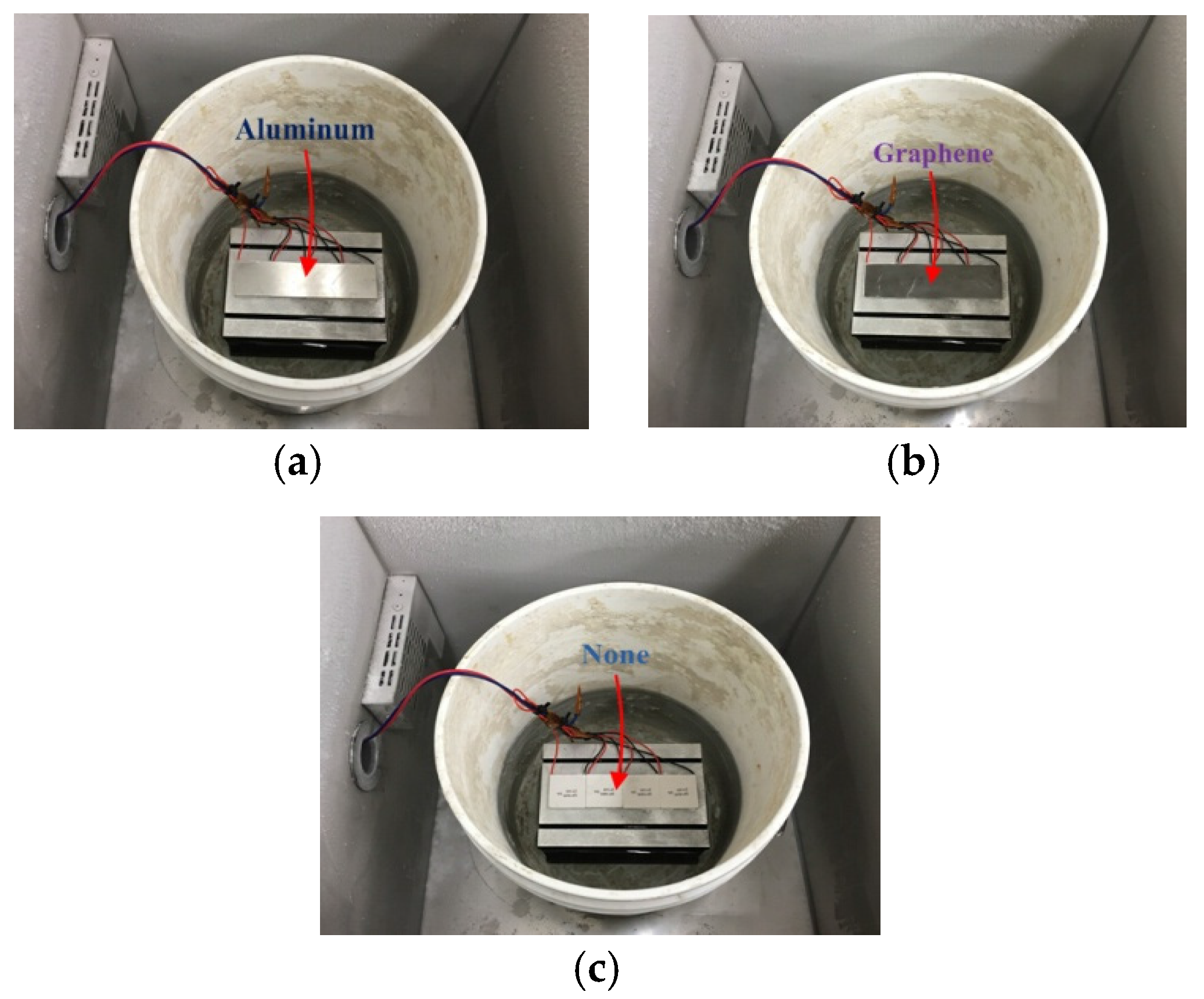
To improve the thermal conduction for TE board power generation system, two different thermally conductive materials (aluminum (K = 230 W/(m·K), thickness = 0.3 mm) and graphene (K = 1200 W/(m·K), thickness = 3.35 × 10⁻⁷ mm)) have been attached to the surface of TE modules. The prototype without any thermally conductive material was also tested for the control study. Figure 7a–c shows photographs of the TE modules attached with aluminum, grapheme and air, respectively.
The simulation results are shown in Figure 8. With the increase of temperature difference between indoor and outdoor from 10 °C to 100 °C, the efficiency of TE board with or without thermally conductive materials increases monotonically.
After 20 °C, it is obvious that the conversion efficiency of TE board with the graphene is higher than that with the aluminum. The conversion efficiency of TE board without any conductive material is maintained at 2.0–2.5% from 30 °C to 100 °C. The simulation results show that the conversion efficiency could be improved by using the material with higher thermal conductance. With the attachment of graphene, the efficiency is enhanced to 1.75%, 2.0% and 2.3% when the temperature difference was 20 °C, 50 °C and 100 °C, respectively.
This simulation on the materials with different conductance is carried out based on the software package MATLAB/Simulink (Mathworks, Natick, MA, USA), according to the mathematic model given before. The conversion efficiencies for the materials are calculated via Equation (19). The relevant parameters of conductance for Aluminum and Graphene that are substituted into the equation are 155 W/(m·K) and 1200 W/(m·K).
4. Experimental Results and Discussion
Figure 9 shows the experimental setup of a power generation system based on TEGs, which was implemented on the mimicked board made of a cooling fin with the size of 180 mm (L) × 125 mm (W) × 135 mm (H), as shown in Figure 10. A high-performance TE module was adopted as the core energy harvesting part in the system.
To evaluate the performance, 4 pieces of TE modules were connected electrically in series, which were attached on the cooling fin using the thermal conductive silicone as the cold side (outdoor). The cold side temperature was maintained at 0 °C by the freezer with the ice water. Therefore, the temperature difference is equal to the ambient temperature. The other surface of the TEGs was the hot side (indoor) attached with different thermally conductive materials. The energy of temperature difference between indoor and outdoor can be transmitted to TEGs, and the terminal voltage was controlled by a buck converter for charging a 32 V/6 F supercapacitor. The thermally conductive materials would help to enhance the conversion efficiency, resulting in the improvement of the overall efficiency.
As we know, there are little differences between the mimicked board and real board, especially in the material. However, this paper was focused on the relationships of the surface of board, different thermally conductive materials and temperature difference, to verify the mathematic model proposed above could be used for any different kinds of materials of board.
To analyze the output characteristic of the TE board power generation system with using different thermally conductive materials, the output voltage of TE board against time was measured without connecting the circuit and load. The experiments using different thermally conductive materials were carried out under the same situation in which the temperature was increased from 0 °C to 40 °C in 2 s. Figure 11 shows the measured waveform of the output voltage of the TE board without attached with the thermally conductive material. It took 0.82 s for the output voltage to increase from 0 V to 2 V.
Figure 12 and Figure 13 show the measured waveforms of the output voltage of the TE board with aluminum and graphene attached as the thermally conductive materials, respectively. The output voltage with the aluminum increased from 0 V to 2 V within 0.63 s. On the other hand, with using the graphene, the time was further reduced to 0.395 s. As the thermal conductance of aluminum is lower than that of graphene, the speed of TE board output voltage increment is proportional to the thermal conductance of conductive material.
Figure 14 shows the measured output voltage and current of the TE board (with graphene attached) power generation system in which a control circuit, including a voltage regulator circuit and a buck converter, was connected and a supercapacitor was the load. It can be seen that the buck converter started to work after the output voltage of the TE board achieved 3.9 V. After 0.5 s, the output voltage of buck converter became constant at 5 V for charging the supercapacitor. The output current of TE board increased to 2.6 mA slowly, particularly when compared to the speed of voltage increment.
Figure 15 shows the measured output voltage and current of the TE board (attached with the graphene) power generation system against different loads. The temperature difference was regulated from 0 °C to 40 °C. It was found that, with increasing load, the output voltage increased while the current decreased. The experimental result was similar to the previous results measured with the TEG module only.
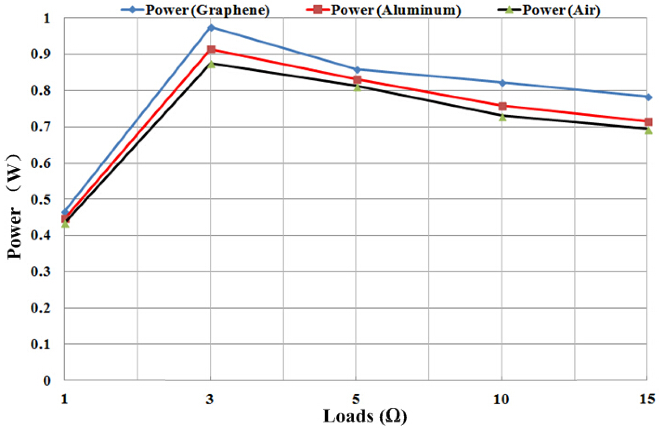
Figure 16 shows the output power of TE board attached with different thermally conductive materials under the same experimental condition as above. Among the three systems, the one with graphene attached show the highest output in different loads, approaching 1 W when the load was 3 Ω. Meanwhile, the maximum power point has been achieved. When the loads decreased from 3 Ω to 5 Ω, the output power declined rapidly, but the declining tendency became steadier beyond 5 Ω.
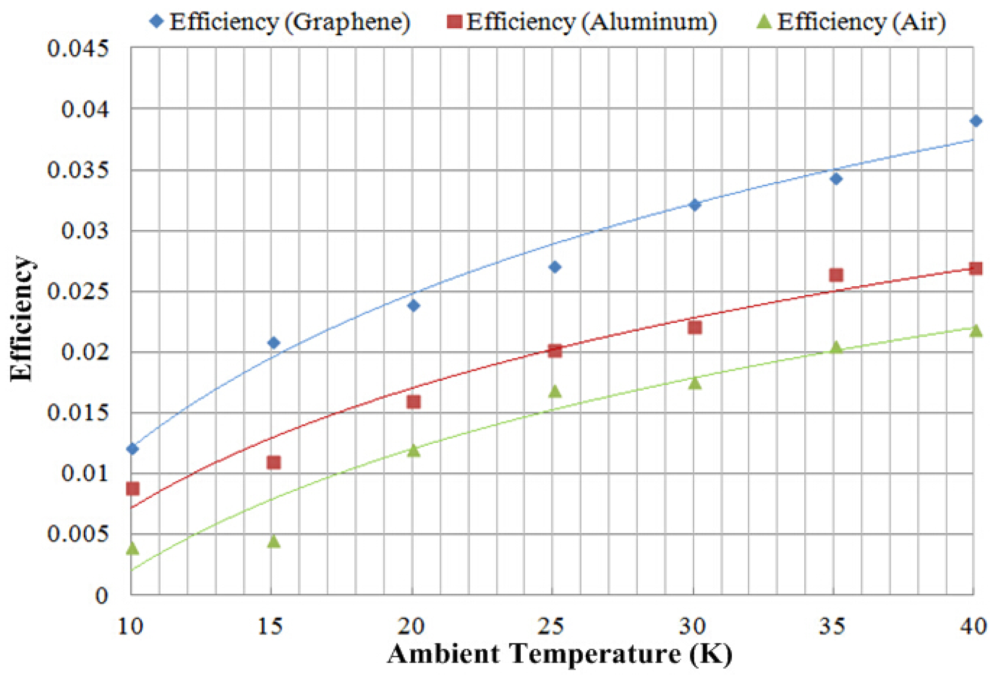
Figure 17 shows that the experimental conversion efficiency of the TE board power generation system attached with different thermally conductive materials against the temperature difference. The trends agree well with the simulated results (Figure 8). The conversion efficiency was improved by using the conductive material with high thermal conductance. The efficiency was enhanced by 1.6%, 1.6% and 1.7% with graphene attached when the temperature difference was 15 °C, 30 °C and 40 °C, respectively. In this study, the supercapacitor was used for energy storage from the TE board power generation system because of the low output voltage from the small TE module. However, in the practical application, the TE board should be much bigger to produce much higher voltage so that the battery could be adopted for the system as the storage element.
5. Conclusions
TEGs have been studied with the board configuration and supercapacitor as the energy storage. Two different thermally conductive materials have been adopted for the improvement of the TE board system. Firstly, the thermal model of TE board has been built for analyzing the thermal characteristics. Moreover, a buck converter has been designed as the control model of the proposed system. The function of the buck converter was to maintain the output voltage generated from the TE board for the supercapacitor. Secondly, the thermal model proved that the conversion efficiency could be enhanced by increasing thermal conductance K. Therefore, aluminum and graphene were employed in the system as thermally conductive materials, and the corresponding simulation results have verified the derivation. Thirdly, the experiments show that the TE board power generation system can provide a stable power output, and the conversion efficiency could be improved by a material with high thermal conductance. The proposed TE system works well with floating solar power station and electric vehicle (EV), which has hot and cool surfaces. The enhanced efficiency of 1.6% is then significant for large scale TEG power generation system when working with the solar and EV, as their total power generation volumes are rather large. The entire power generation would be greatly improved, ultimately economically, and produce a valuable renewable energy.
Acknowledgments
The authors gratefully acknowledge the support of Research Committee of the Hong Kong Polytechnic University under the project reference H-ZDB9.
Author Contributions
Siyang Li developed the analysis, hardware design and measurement. He also conducted the simulation of the work. Kwok Ho Lam and Ka Wai Eric Cheng were responsible for the background theory. He also provided the guidance and supervision of study.
Conflicts of Interest
The authors declare no conflict of interest.
References
- Zou, Y.; Cheng, K.W.E. A Vertical Flux-Switching Permanent Magnet Based Oscillating Wave Power Generator with Energy Storage. Energies 2017, 10, 887. [Google Scholar] [CrossRef]
- Singh, M.; Singh, J.; Garg, A. Efficient autonomous solar panel and thermo-electric Generator (TEG) integrated hybrid energy harvesting system. In Proceedings of the Progress in Electromagnetic Research Symposium (PIERS), 8–11 August 2016; pp. 1764–1768. [Google Scholar]
- Harihara Krishnan, S.; Ezhilarasi, D.; Uma, G.; Umapathy, M. Pyroelectric-based solar and wind energy harvesting system. IEEE Trans. Sustain. Energy 2014, 5, 73–81. [Google Scholar] [CrossRef]
- Su, S.H.; Chen, J.C. Simulation investigation of high-efficiency solar thermoelectric generators with in homogeneously doped nonmaterial. IEEE Trans. Ind. Electron. 2015, 62, 3569–3575. [Google Scholar]
- Yang, D.J.; Yin, H.M. Energy conversion efficiency of a novel hybrid solar system for photovoltaic, thermoelectric, and heat flux utilization. IEEE Trans. Energy Convers. 2011, 26, 662–670. [Google Scholar] [CrossRef]
- Rodriguez, R.; Preindl, M.; Emadi, A.; Cotton, J. Maximum power point tracking for thermoelectric generators with high frequency injection. In Proceedings of the 41st Annual Conference of the IEEE Industrial Electronics Society (IECON 2015), Yokohama, Japan, 9–12 November 2015; pp. 4127–4132. [Google Scholar]
- Wang, Y.; He, H.M.; Wang, J.; Bai, B.D. Research of novel water cooling jacket for explosion-proof motor. In Proceedings of the 2013 International Conference on Electrical Machines and Systems (ICEMS), Busan, Korea, 26–29 October 2013; pp. 691–694. [Google Scholar]
- Moon, S.H.; Yun, J.H.; Kim, W.G.; Kim, J.P. Thermal-flow analysis and cooling performance enhancement of a totally enclosed fan-cooled motor. In Proceedings of the 2013 International Conference Electrical Machines and Systems (ICEMS), Busan, Korea, 10–12 August 2014; pp. 2028–2030. [Google Scholar]
- Deng, F. Wearable thermoelectric power generators combined with flexible supercapacitor for low-power human diagnosis devices. IEEE Trans. Ind. Electron. 2017, 64, 1477–1485. [Google Scholar] [CrossRef]
- Wakitani, S.; Deng, M.; Ichikawa, A. Operator based MPPT scheme of power generation system using thermoelectric devises. In Proceedings of the 2014 International Conference on Advanced Mechatronic Systems (ICAMechS) 2014 Int. Conf. Adv. Mechatron. Systems, Kumamoto, Japan, 10–12 August 2014; pp. 382–386. [Google Scholar]
- Siyang, L.; Lam, K.H.; Cheng, K.W.E. Development of a motor waste heat flux power generation system based on thermoelectric generators. In Proceedings of the 2016 International Symposium on Electrical Engineering (ISEE), Hong Kong, China, 14 December 2016. [Google Scholar]
- Kyono, T.; Suzuki, R.O.; Ono, K. Conversion of unused heat flux energy to electricity by means of thermoelectric generation in condenser. IEEE Trans. Energy Convers. 2013, 18, 330–334. [Google Scholar] [CrossRef]
- Masuda, C.; Deng, M. Thermoelectric generation system design with considering heat flux output dynamics and its application to motor car. In Proceedings of the 54th Annual Conference of the IEEE, Hangzhou, China, 28–30 July 2015. [Google Scholar]
- Anamaria, E.; Schaltz, E.; Rosendahl, L.; Rezaniakolaei, A.; Platzek, D. A High Temperature Experimental Characterization Procedure for Oxide-Based Thermoelectric Generator Modules under Transient Conditions. Energies 2015, 8, 12839–12847. [Google Scholar]
- Ming, T.Z.; Wang, Q.K.; Peng, K.Y.; Wei, Z.C.; Tang, Y.J.; Wu, Y.; Gong, T.R. The Influence of Non-Uniform High Heat Flux on Thermal Stress of Thermoelectric Power Generator. Energies 2015, 8, 12584–12602. [Google Scholar] [CrossRef]
- Goldsmid, H.J. Conversion Efficiency and Figure-of-Merit, CRC Handbook of Thermoelectric; Rowe, M.M., Ed.; Chemical Rubber Company: Cleveland, OH, USA, 1995; pp. 19–25. [Google Scholar]
- Krutov, V. (Ed.) Technical Thermo Dynamics; Vishaya Shkola: Moscow, Russian, 1971. (In Russian) [Google Scholar]
- Wang, Y.; Ajit, K.; Vallabhaneni, B.Q.; Ruan, X.L. Two-dimensional thermal transport in graphene: A review of numerical modeling studies. Nanosci Microsc. Thermophys. Eng. 2014, 18, 155–182. [Google Scholar] [CrossRef]
- Qiu, B.; Wang, Y.; Zhao, Q.; Ruan, X.L. The effects of diameter and chirality on the thermal transport in free-standing and supported carbon-nanotubes. Appl. Phys. Lett. 2012, 23, 633–638. [Google Scholar]
- Chen, M.; Rosendahl, L.A.; Condra, T.C.; Pedersen, J.K. Numerical modelling of thermoelectric generators with varing material properties in a circuit simulator. IEEE Trans. Energy Convers. 2009, 24, 112–124. [Google Scholar]
- Lineykin, S.; Ben-Yaakov, S. Modelling and analysis of thermoelectric modules. IEEE Trans. Ind. Appl. 2015, 43, 505–512. [Google Scholar] [CrossRef]
- Ye, Y.-M.; Eric Cheng, K.W. Quadratic boost converter with low buffer capacitor stress. IET Power Electron. 2014, 7, 1162–1170. [Google Scholar] [CrossRef]
- Law, K.K.; Eric Cheng, K.K. Examination of the frequency modulation and lifting techniques for the generalized power factor correction switched-capacitor resonant converter. Int. J. Circuit Theor. Appl. 2007, 36, 839–855. [Google Scholar] [CrossRef]
- Li, S.; Cheng, K.W.E.; Ye, Y.M.; Shi, Z.G. Wide input and wide output topology analysis for tapped-inductor converters with consideration of parasitic elements. IET. Power Electron. 2016, 9, 1952–1961. [Google Scholar] [CrossRef]
- Siouane, S.; Jovanovic, S.; Poure, P. Equivalent Electrical Circuit of Thermoelectric Generators under Different Operating Conditions. Energies 2017, 10, 386. [Google Scholar] [CrossRef]
- Cheng, K.W.E. Storage energy for classical switched mode power converters. IEE Proc.-Electr. Power Appl. 2003, 150, 439–446. [Google Scholar] [CrossRef]
Figure 1.
The schematic of the fundamental unit of a TE module embedded in a board with a thermally conductive material.
Figure 1.
The schematic of the fundamental unit of a TE module embedded in a board with a thermally conductive material.

Figure 2.
Control diagram of TE Board power generation system.
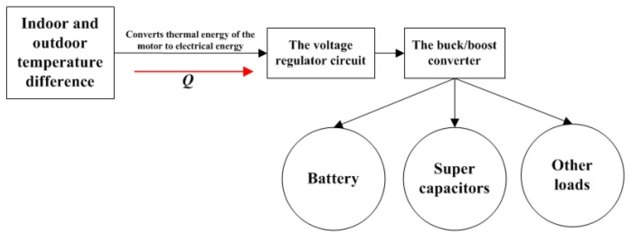
Figure 3.
Equivalent circuit model of the TE Board power generation system.
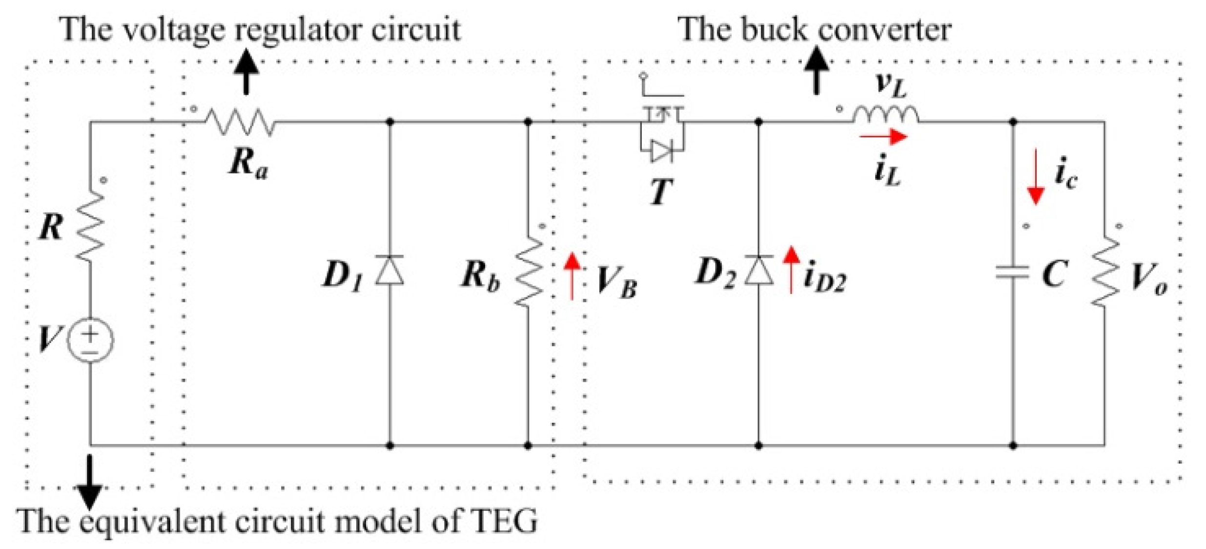
Figure 4.
Measured results of the output current versus different loads of TEG module in five temperature difference situations.
Figure 4.
Measured results of the output current versus different loads of TEG module in five temperature difference situations.
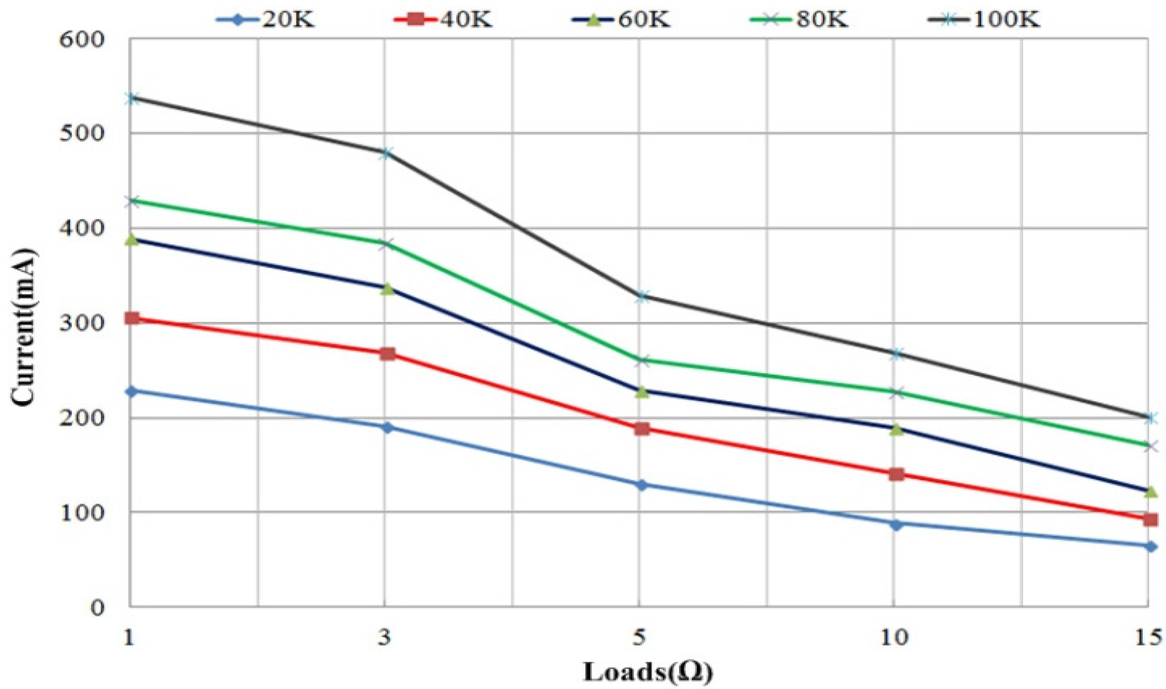
Figure 5.
Measurement results of the output voltage versus different loads of TEG module in five temperature difference situations.
Figure 5.
Measurement results of the output voltage versus different loads of TEG module in five temperature difference situations.

Figure 6.
Measured results of the output power versus different loads of TEG module in five temperature difference situations.
Figure 6.
Measured results of the output power versus different loads of TEG module in five temperature difference situations.
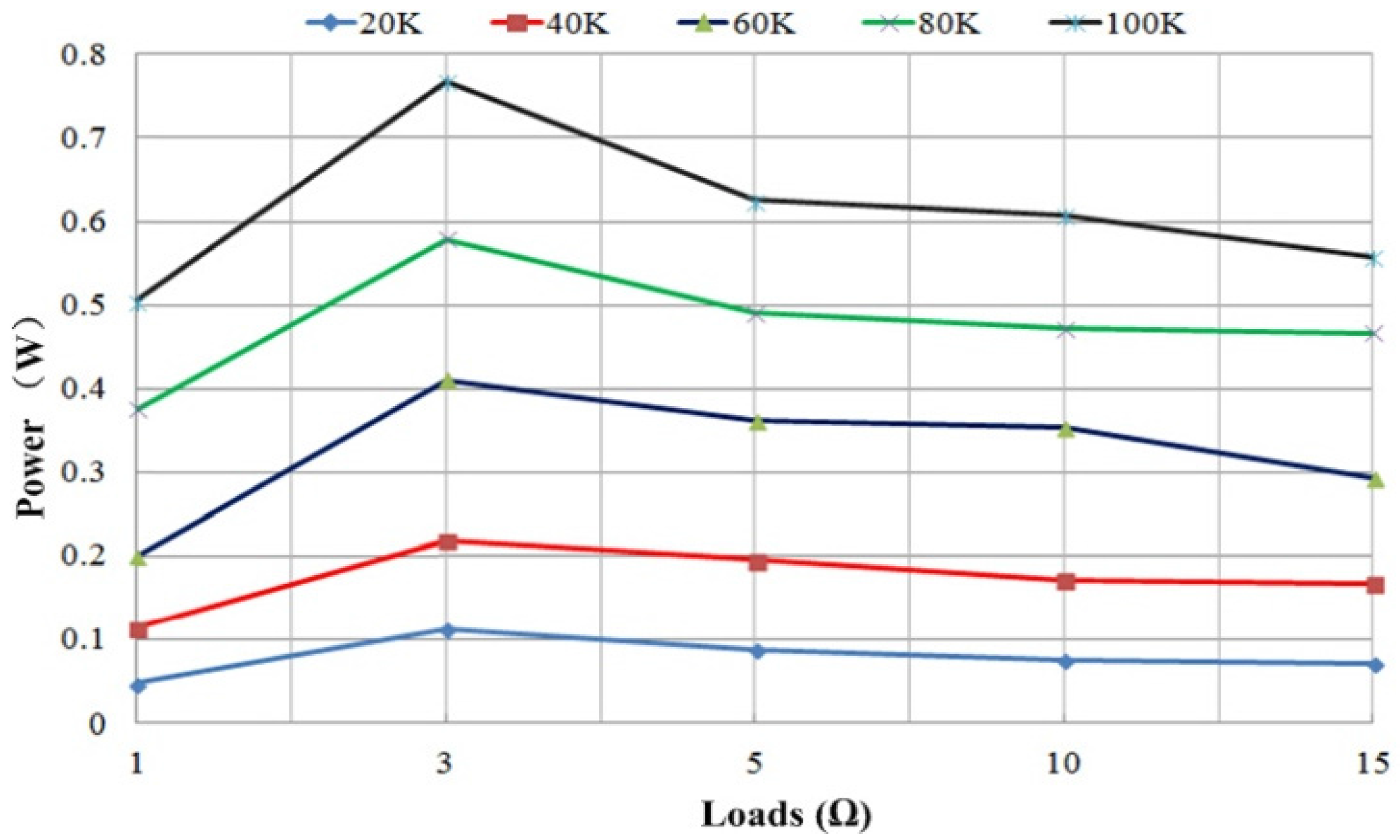
Figure 7.
Photographs of the prototype of TE board power generation system with different thermally conductive materials, (a) Air; (b) Aluminum; and (c) Graphene.
Figure 7.
Photographs of the prototype of TE board power generation system with different thermally conductive materials, (a) Air; (b) Aluminum; and (c) Graphene.

Figure 8.
Simulation results of conversion efficiency of TE board with using different thermally conductive materials.
Figure 8.
Simulation results of conversion efficiency of TE board with using different thermally conductive materials.
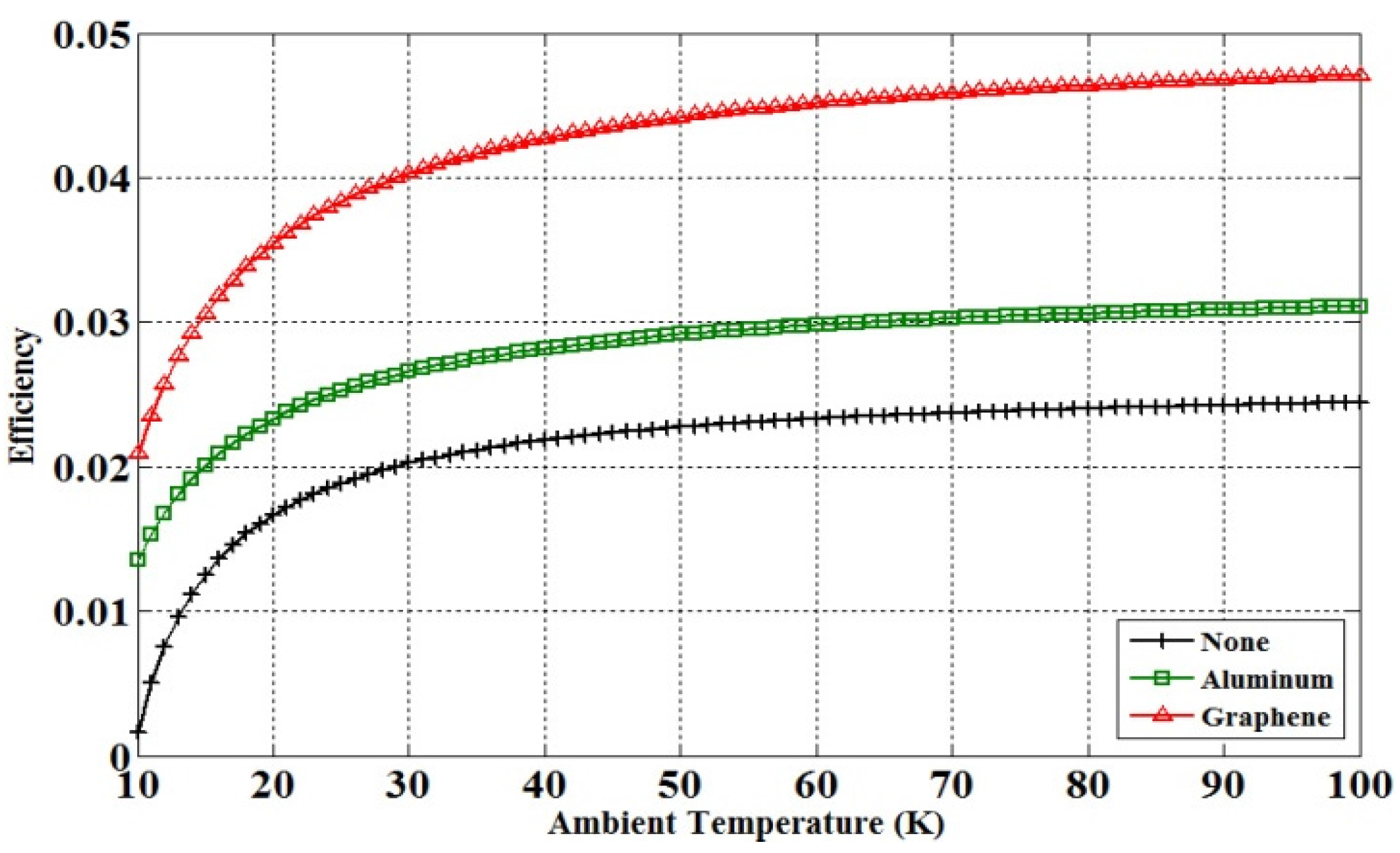
Figure 9.
Photograph of the experimental setup of the TE board power generation system.
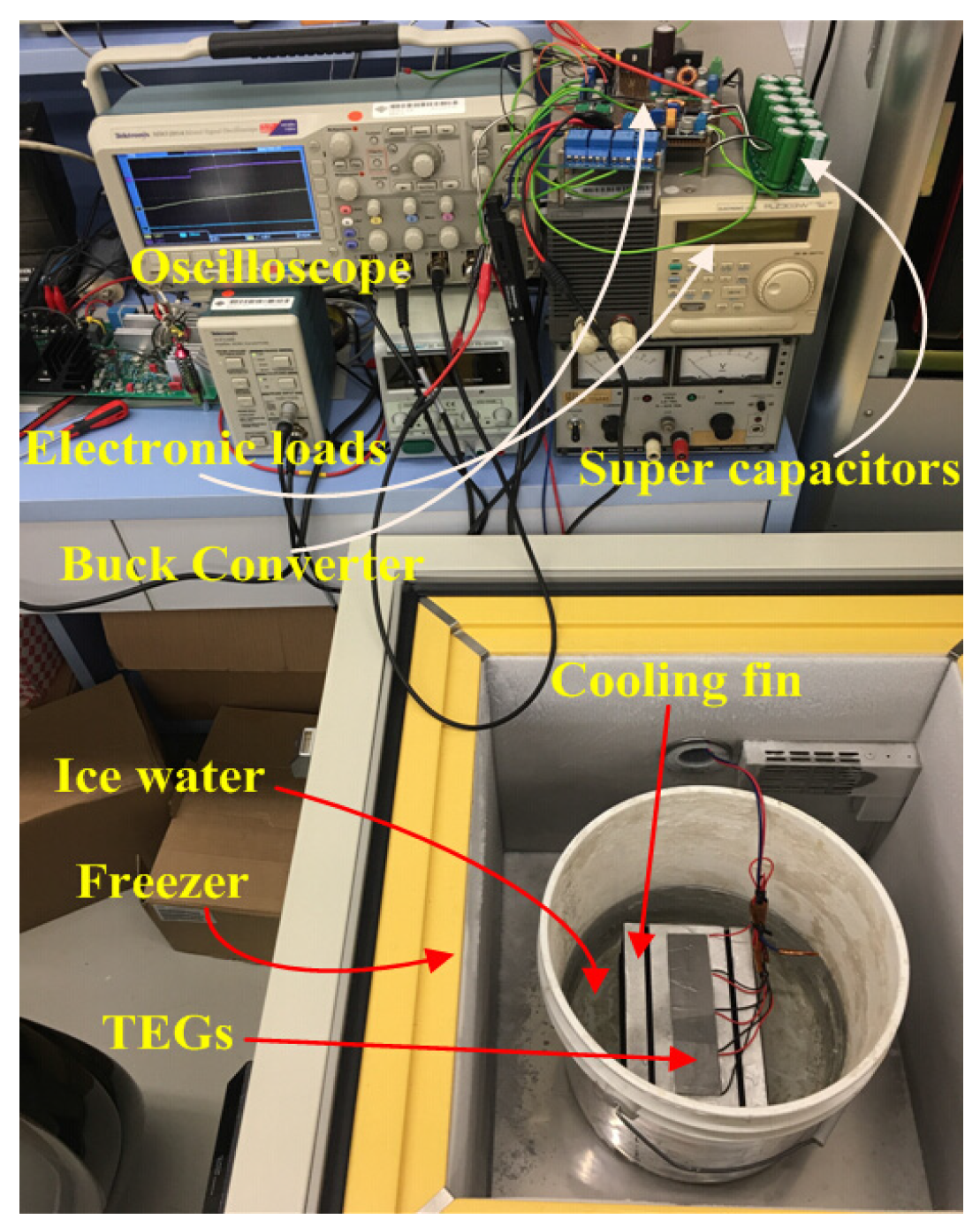
Figure 10.
Photograph of the mimicked board.
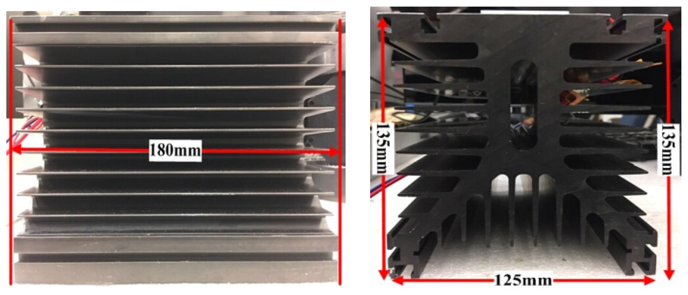
Figure 11.
Measured waveform of the output voltage (Channel 1) of the TE board without attaching the thermally conductive material.
Figure 11.
Measured waveform of the output voltage (Channel 1) of the TE board without attaching the thermally conductive material.

Figure 12.
Measured waveform of the output voltage (Channel 1) of the TE board with aluminum attached as the thermally conductive material.
Figure 12.
Measured waveform of the output voltage (Channel 1) of the TE board with aluminum attached as the thermally conductive material.
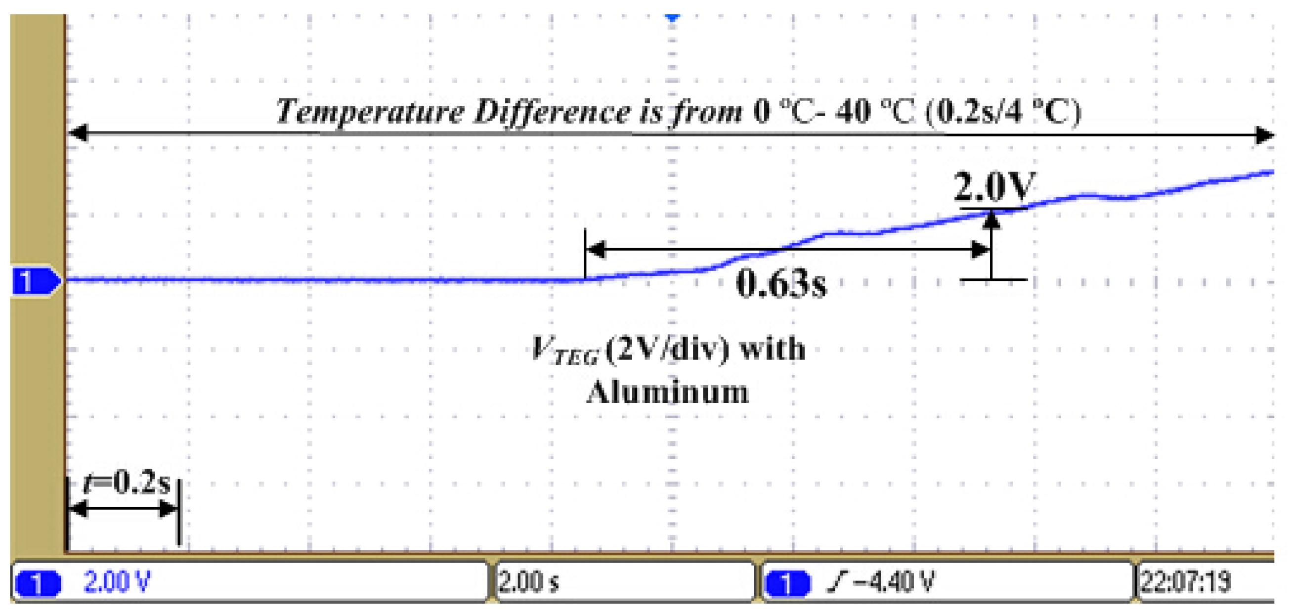
Figure 13.
Measured waveform of the output voltage (Channel 1) of the TE board with graphene attached as the thermally conductive material.
Figure 13.
Measured waveform of the output voltage (Channel 1) of the TE board with graphene attached as the thermally conductive material.
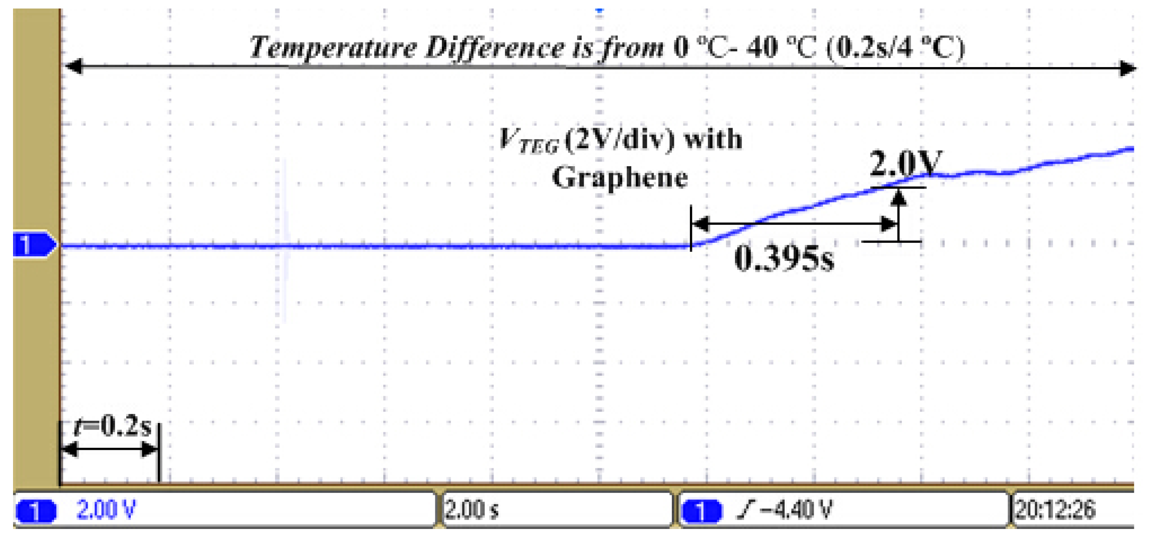
Figure 14.
Channel 1 is output voltage, Channel 2 is output current, and Channel 3 is constant output voltage of buck converter for supercapacitor is 5.0 V.
Figure 14.
Channel 1 is output voltage, Channel 2 is output current, and Channel 3 is constant output voltage of buck converter for supercapacitor is 5.0 V.

Figure 15.
The output voltage and current of TE board with graphene in different loads.
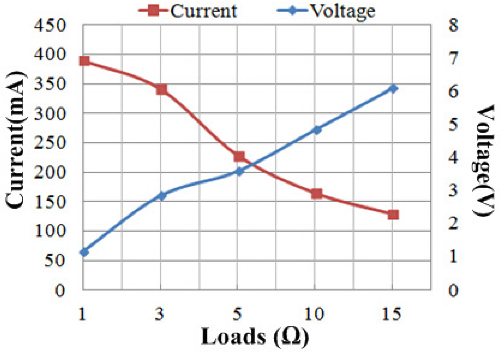
Figure 16.
The output power of TE board with different thermally conductive materials in different loads.
Figure 16.
The output power of TE board with different thermally conductive materials in different loads.

Figure 17.
Conversion efficiency of TE board attached with different thermally conductive materials against temperature difference.
Figure 17.
Conversion efficiency of TE board attached with different thermally conductive materials against temperature difference.
© 2017 by the authors. Licensee MDPI, Basel, Switzerland. This article is an open access article distributed under the terms and conditions of the Creative Commons Attribution (CC BY) license (http://creativecommons.org/licenses/by/4.0/).
Share and Cite
MDPI and ACS Style
Li, S.; Lam, K.H.; Cheng, K.W.E. The Thermoelectric Analysis of Different Heat Flux Conduction Materials for Power Generation Board. Energies 2017, 10, 1781. https://doi.org/10.3390/en10111781
AMA Style
Li S, Lam KH, Cheng KWE. The Thermoelectric Analysis of Different Heat Flux Conduction Materials for Power Generation Board. Energies. 2017; 10(11):1781. https://doi.org/10.3390/en10111781
Chicago/Turabian StyleLi, Siyang, Kwok Ho Lam, and Ka Wai Eric Cheng. 2017. "The Thermoelectric Analysis of Different Heat Flux Conduction Materials for Power Generation Board" Energies 10, no. 11: 1781. https://doi.org/10.3390/en10111781
Note that from the first issue of 2016, this journal uses article numbers instead of page numbers. See further details here.