Article

Sliding Mode and Neural Network Control of Sensorless PMSM Controlled System for Power Consumption and Performance Improvement

Department of Electrical Engineering, Southern Taiwan University of Science and Technology, 1, Nan-Tai St., Yung Kang District, Tainan City 710, Taiwan
*
Author to whom correspondence should be addressed.
Energies 2017, 10(11), 1780; https://doi.org/10.3390/en10111780
Submission received: 14 October 2017 / Revised: 30 October 2017 / Accepted: 1 November 2017 / Published: 5 November 2017
(This article belongs to the Special Issue Selected Papers from IEEE ICICE 2017)

Abstract

:
This paper deals with the design of sliding mode control and neural network compensation for a sensorless permanent magnet synchronous motor (PMSM) controlled system that is able to improve both power consumption and speed response performance. The position sensor of PMSM is unreliable in harsh environments. Therefore, the sensorless control technique is widely proposed in industry. A sliding mode observer can estimate the rotor angle and has the robustness to load disturbance and parameter variations. However, the sliding mode observer is not conducive to standstill and low speed conditions because the amplitude of the back EMF is almost zero. As a result, this paper combines an iterative sliding mode observer (ISMO) and neural networks (NNs) as an angle compensator to improve the above problems. A dsPIC30F6010A-based PMSM sensorless drive system is implemented to validate the proposed algorithm. The simulation and experimental results prove its effectiveness.

1. Introduction

It is well-known that electric motors are the single biggest consumer of electricity in modern society and their consumption of industrial and domestic electric motors per year occupy 46.2% of the global electrical demand [1]. In addition, it is estimated that about 20% to 30% of the total global electric motor demand may be saved if the more efficient electric motors and drives are designed and used. The permanent magnet synchronous motor (PMSM) provides some eminent properties, such as high power density/reliability and easy controllability/maintenance, such that it has been widely used in servo motors, robotics, and electric vehicles of industry applications. The excellent performance of PMSM drive systems comes from the information of rotor position that is measured by position sensors (encoders or resolvers) of the motors. However, the disadvantages of shaft sensors result into larger machine volume, expense, and noise problems, and limit the applications because of the harsh environment of high humidity and temperature. As a result, extensive research of sensorless control strategies has been conducted on overcoming these problems [2,3].
For standstill and low speed conditions, signal injection methods [4,5,6,7], which inject the high-frequency voltage and current signals to detect or estimate the rotor position, are the popular candidates of sensorless control schemes. Control methods based on carrier signal injection [6] are proposed for sensorless motor control. An innovative self-sensing control scheme based on test current instead of voltage injection [7] is used to deal with problems on sensorless control of PMSM. A two-degree-of-freedom control scheme plays the main role, which needs the information of model dynamics.
At medium- and high-speed ranges, the fundamental excitation methods [3,8,9,10], which are based on the motor model and use the fundamental signals of voltages and currents for the rotor position and speed detection, are adopted by most researchers. An online identification method by affine projection algorithms in the estimated synchronously rotating frame that is able to estimate its stator resistance and inductances accurately for the model-based sensorless control of interior PMSMs is proposed in [3]. An extended Kalman filter (EKF) [8] is usually used to an obtain good performance of sensorless control, however it is complex and difficult to implement. By feeding back stator currents and voltages, a sixth order nonlinear adaptive controller is designed to address the tracking problem with unknown constant load torque for the sensorless PMSM system [9]. However, the proposed control algorithm is just simulated without experimentation. A high-speed sliding-mode observer [9] for estimating the rotor position and the velocity of PMSM from the back electromotive force (EMF) is proposed.
Considering the rotor position error during motor starting to lower speeds, this paper proposes an iterative sliding mode observer (ISMO) [11,12], combined with an artificial neural network (ANN) to fix the problem. The ISMO will make the sensorless control system robust against disturbance and parameter variations. Similar to the concept of multi-loop servo control systems, the ISMO internally estimates the back EMF several times within a speed control cycle to reduce the ripples of the estimated back EMF, and then externally calculates the position and velocity of the rotor once to obtain accurate estimations. In order to reduce the chattering effect in the sliding mode behavior, a sigmoid function replaces a traditional switching function. In addition, because of their good characteristics of having parallel distributed architecture and the ability to identify nonlinear system dynamics and to learn, generalize, and adapt to a new environment, ANNs have attracted much attention to more engineering applications recently [13,14,15,16]. Sensorless motor control is one of excellent example.
The rest of the paper is organized as follows. Section 2 consists of PMSM modeling, iterative sliding mode observer, and compensation for rotor angle estimation by neural networks to form the servo system design. Section 3 is composed of results of simulation by Matlab/Simulink and experiments. Finally, Section 4 gives conclusions.

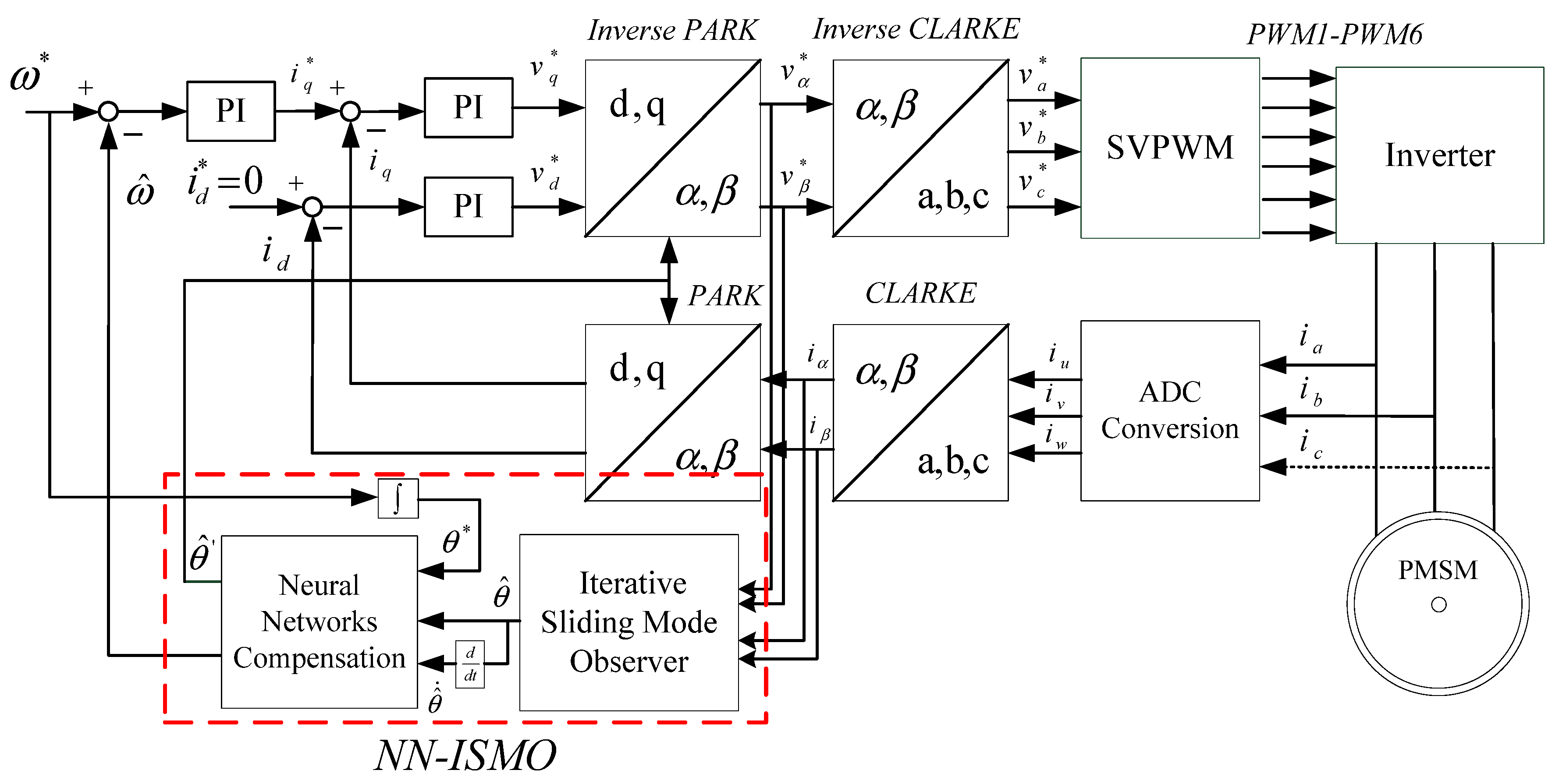
2. Servo System Design

The proposed sensorless servo control system design includes PMSM modeling, iterative sliding mode observer, and rotor angle that is compensated by neural networks.

2.1. PMSM Modeling

The voltage equation of PMSM by Clarke transformation from the three-phase stationary a-b-c frame to the two-phase fixed α β frame is given as [2,3,4,5,6],
[ v α v β ] = [ R s + d d t L s 0 0 R s + d d t L s ] [ i α i β ] + [ e α e β ]
where v α , v β , i α , i β are α - and β -axis voltages and currents respectively; R s and L s are the resistance and inductance; and the back EMFs are given as:
e α = λ f ω r sin θ
e β = λ f ω r cos θ
where λ f is flux linkage by the permanent magnets, ω r is the electric speed and θ is rotor angle. The actual rotor position is absent in a sensorless application and will be estimated by methods. The block diagram of the proposed sensorless PMSM control system is shown in Figure 1. We will first conduct simulation by Matlab/Simulink and experiments to verify the design.

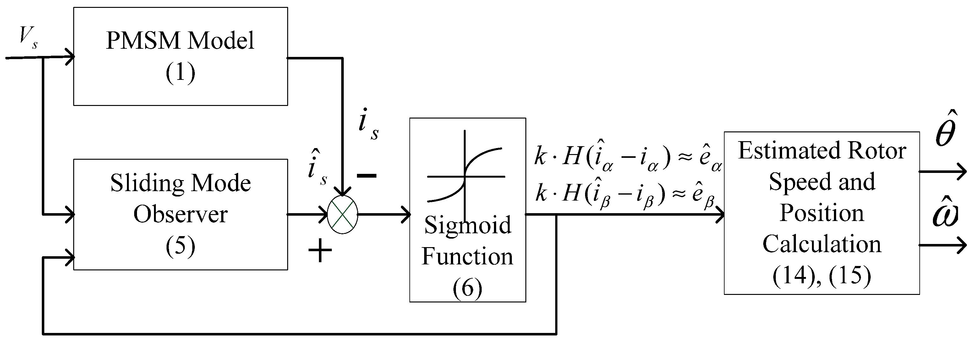
2.2. Iterative Sliding Mode Observer

From (1), we have the stator current differential equation,
d d t i α = R s L s i α 1 L s e α + 1 L s ν α d d t i β = R s L s i β 1 L s e β + 1 L s ν β
A sliding-mode observer (SMO) has not only better performance of sliding-mode control (SMC), like robustness to disturbances and parameter variations [17,18,19,20,21,22,23,24,25,26,27,28,29], but also provides estimation information of rotor position and speed for the sensorless control system. The dynamic equations of SMO are given based on (4),
d d t i ^ α = R s L s i ^ α + 1 L s v α 1 L s k H ( i ^ α i α ) d d t i ^ β = R s L s i ^ β + 1 L s v β 1 L s k H ( i ^ β i β )
where stands for estimation, k is observer gain, and the sigmoid function:
[ H ( i ^ α i α ) H ( i ^ β i β ) ] = [ ( 2 1 + exp ( a ( i ^ α i α ) ) ) 1 ( 2 1 + exp ( a ( i ^ β i β ) ) ) 1 ]
is used to improve the chattering phenomenon in the sliding mode operation and a is a positive constant, shown in Figure 2 [11,12].
The sliding vector for the system is:
S n = [ s α    s β ] T = [ i ^ α i α    i ^ β i β ] T = [ i ¯ α    i ¯ β ] T
and the defined Lyapunov function is:
V = 1 2 S n T S n = 1 2 ( s α 2 + s β 2 )
By Lyapunov’s stability theorem, k will be designed to satisfy the inequality, V ˙ < 0 , when the system trajectory approaches to the sliding surface, S n = 0 . The error equations of estimated currents are:
i ¯ ˙ α = i ^ ˙ α i ˙ α = R s L s i ¯ α + 1 L s e α 1 L s k H ( i ¯ α ) i ¯ ˙ β = i ^ ˙ β i ˙ β = R s L s i ¯ β + 1 L s e β 1 L s k H ( i ¯ β )
For V ˙ = S n T S ˙ n < 0 , we have:
S n T S ˙ n = R s L s ( i ¯ α 2 + i ¯ β 2 ) + 1 L s ( e α i ¯ α k i ¯ α H ( i ¯ α ) ) + 1 L s ( e β i ¯ β k i ¯ β H ( i ¯ β ) ) < 0
Rearranging (10), we have:
S n T S ˙ n = R s L s ( i ¯ α 2 + i ¯ β 2 ) + 1 L s [ ( e α k ) i ¯ α H ( i ¯ α ) + ( e β k ) i ¯ β H ( i ¯ β ) ] < 0
The product of i ¯ α H ( i ¯ α ) (and i ¯ β H ( i ¯ β ) ) is always positive. As a result, if
k max ( | e α | , | e β | )
the inequality of (10) will be satisfied. The sliding mode may then exist on the sliding surface as follows:
[ s ˙ α   s ˙ β ]   T = [ s α   s β ]   T [ 0   0 ]
With (11) to satisfy (10), the following conditions are obtained:
e ^ α = k H ( i ¯ α ) = λ f ω ^ r sin θ ^ e ^ β = k H ( i ¯ β ) = λ f ω ^ r cos θ ^
As a result, and the estimated rotor angle and motor speed are given as:
θ ^ = tan 1 ( e ^ α / e ^ β )
ω ^ = d d t θ ^
The designed SMO (5) will internally estimate the back EMF (13) several times within a speed control cycle to reduce the ripples of the estimated back EMF, and then externally calculate the position and the velocity of the rotor (14) and (15) once to obtain accurate estimations.

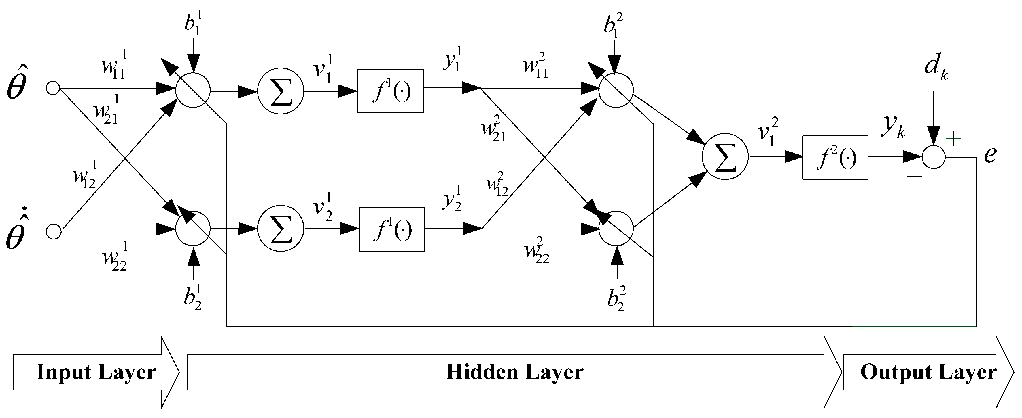
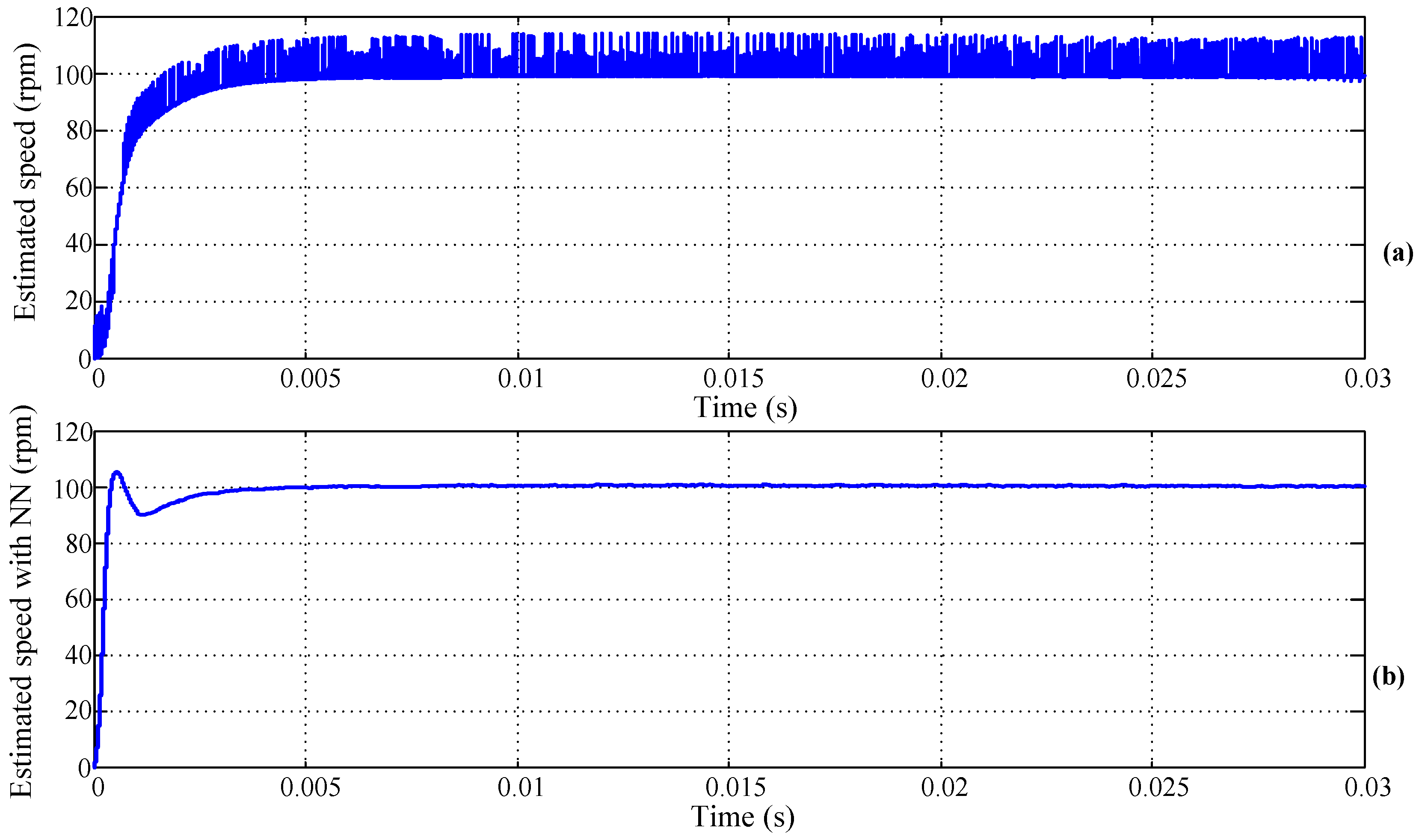
2.3. Neural Networks Compensation

As the problem mentioned previously, a neural network (NN) with error back propagation structure, as shown in Figure 3, is adopted to compensate the rotor position estimation error, which consists of input layer with two inputs, hidden layer with two neurons, and output layer. In Figure 3, θ ^ , and θ ^ ˙ are input variables, w i j n is the weight between the jth neuron of the nth layer and the ith neuron of the (n−1)th layer, b j n is the bias of the jth neuron of the nth layer, v j n is sum of the product sum of outputs and weights and biases of the (n−1)th layer, y j n is output value of jth neuron of the nth layer, y k is sum of the NN, f n is activation function of the nth layer, and d k is the reference rotor angle from the speed command, respectively. The relationships are described in the following two equations:
y j n = f n ( v j n )
v j n = i = 1 w i j n y i n 1 + b j n
The error function is defined as:
e ( k ) = 1 2 k = 1 ( d k y k ) 2
and the reference angle is given as:
d k = θ m ( k + 1 ) = i = 1 k T s ω * ( i ) + θ 0
where ω * ( k ) is the reference speed, T s is the sampling period, and θ 0 is the initial rotor angle. The gradient method is adopted to search the minimum value of (18) by the following equations:
Δ w i j n ( k ) = u e ( k ) w i j n = u e ( k ) v j n v j n w i j n
Δ b j n ( k ) = u e ( k ) b j n = u e ( k ) v j n v j n b j n
w i j n ( k + 1 ) = w i j n ( k ) + Δ w i j n ( k )
b j n ( k + 1 ) = b j n ( k ) + Δ b j n ( k )
where u is the learning rate.

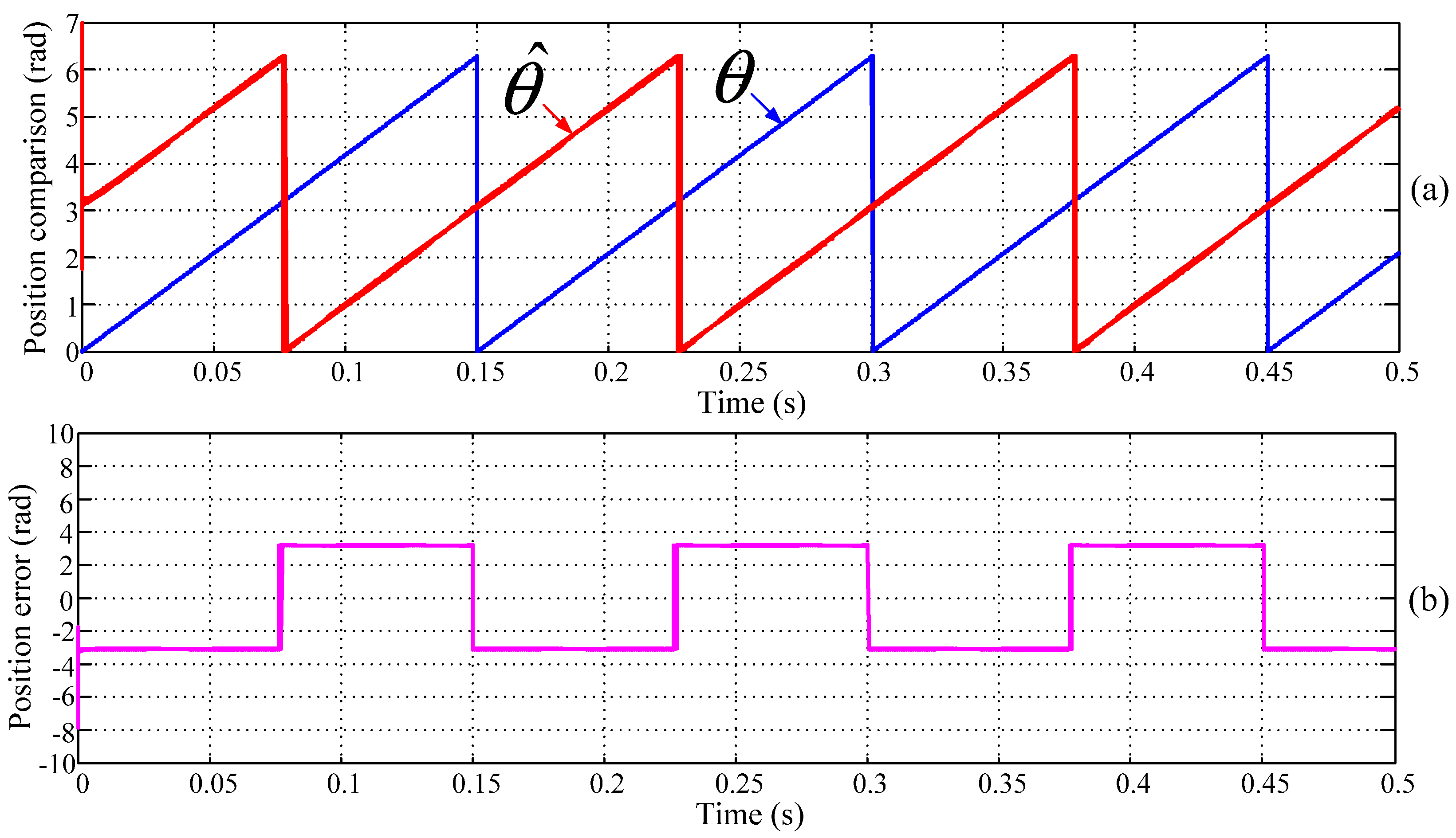
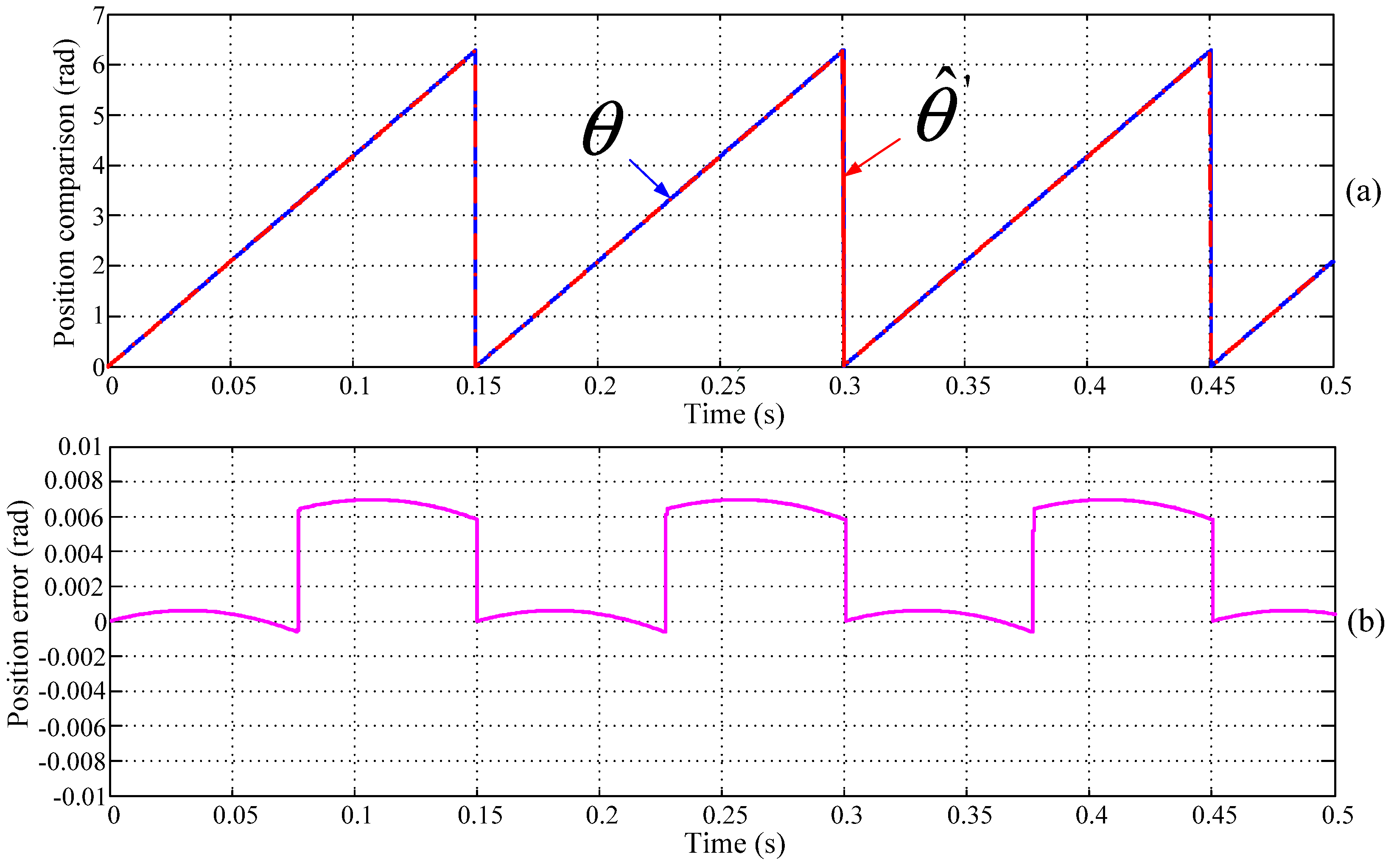
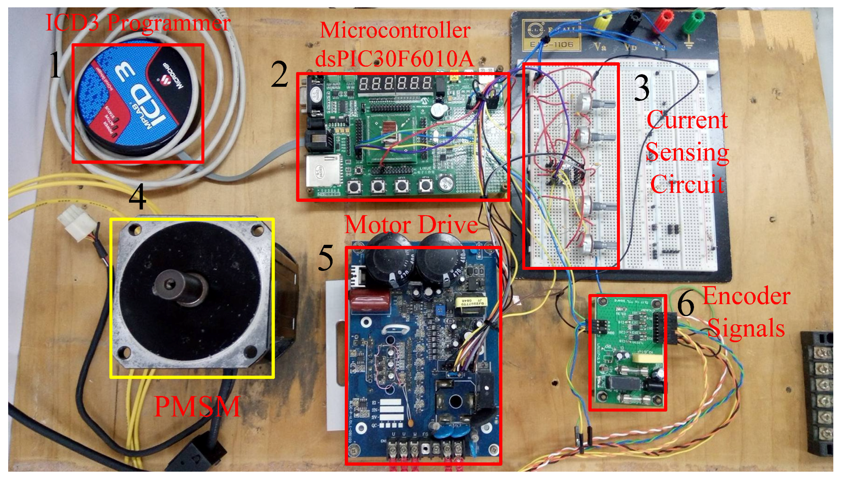
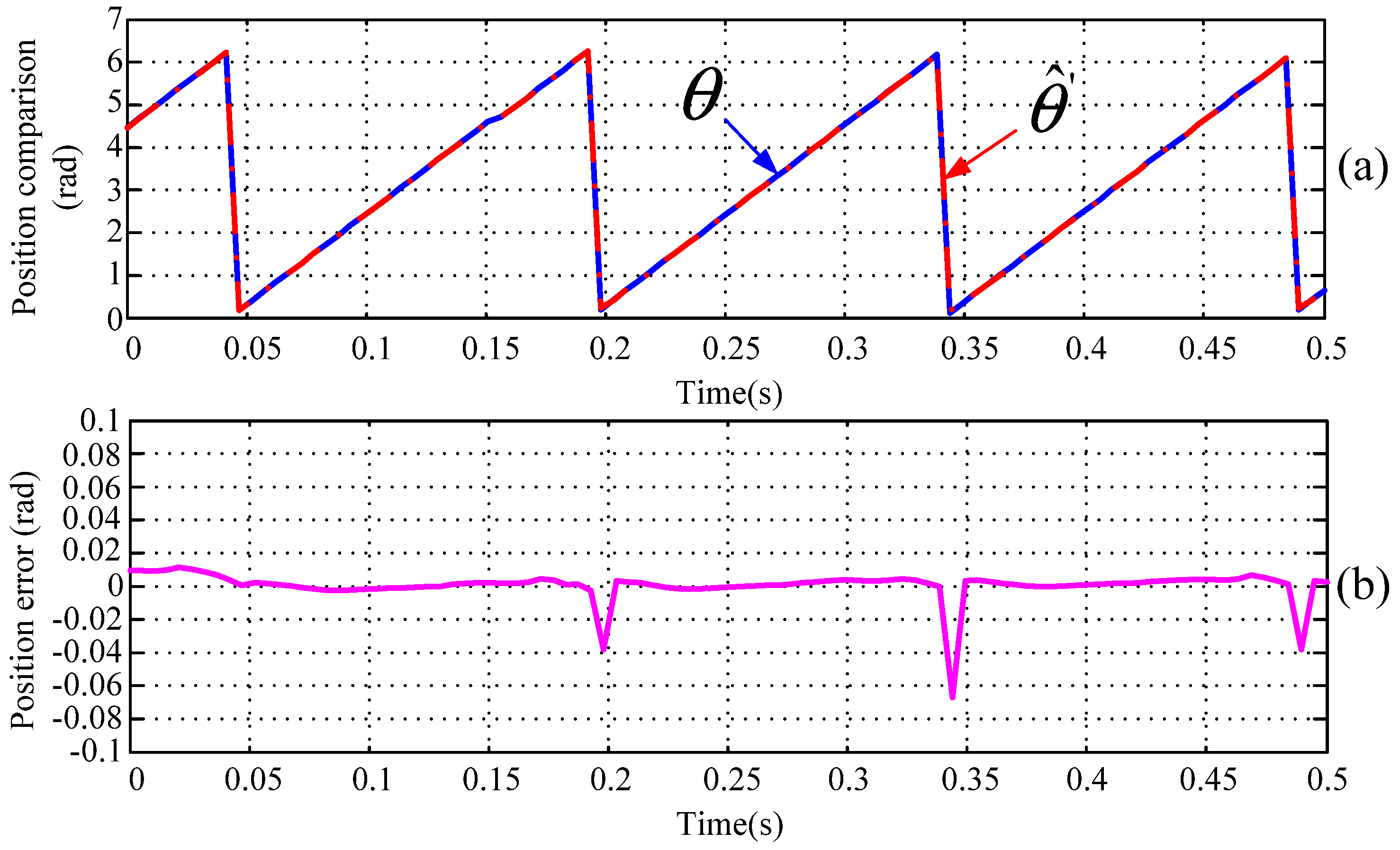
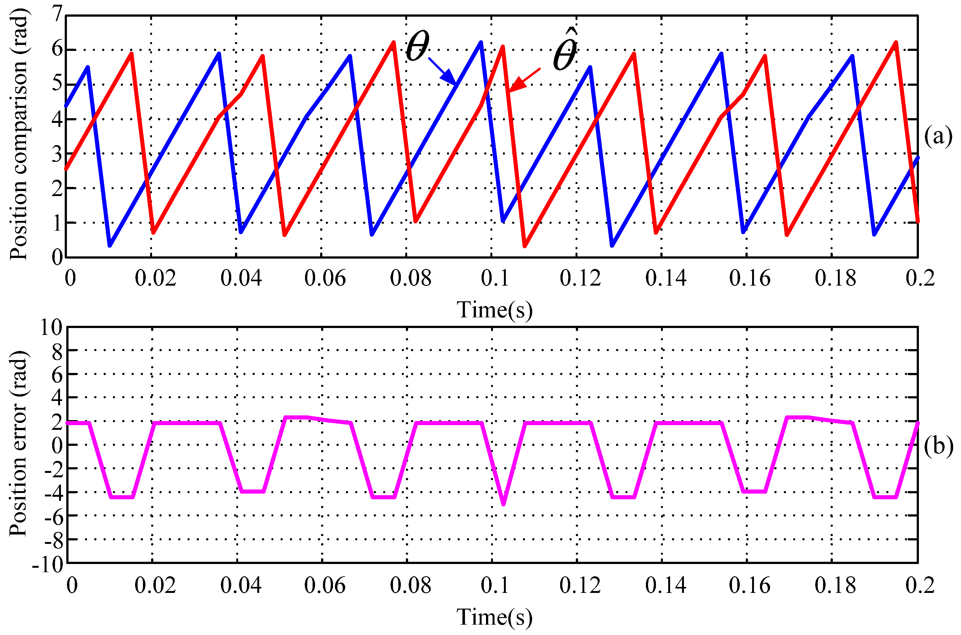
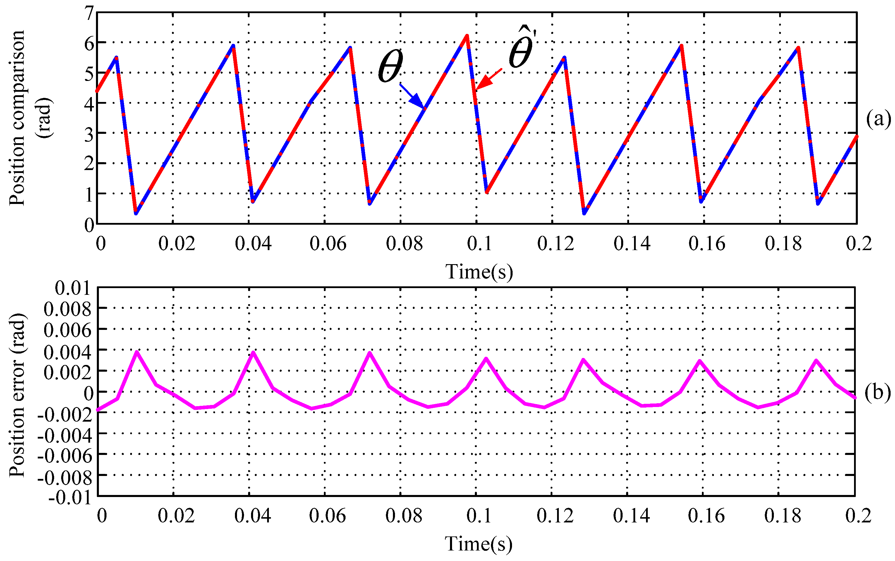
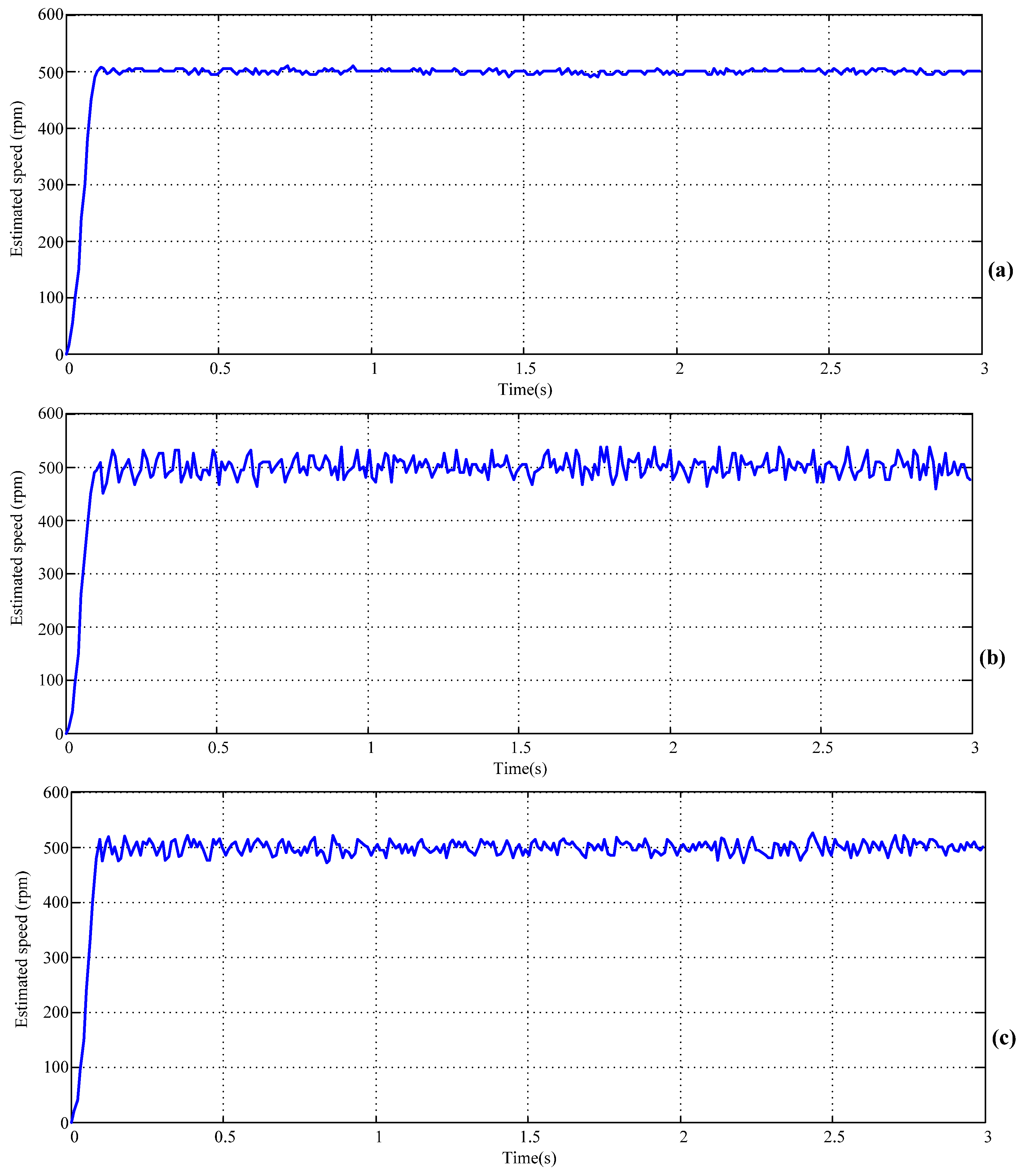
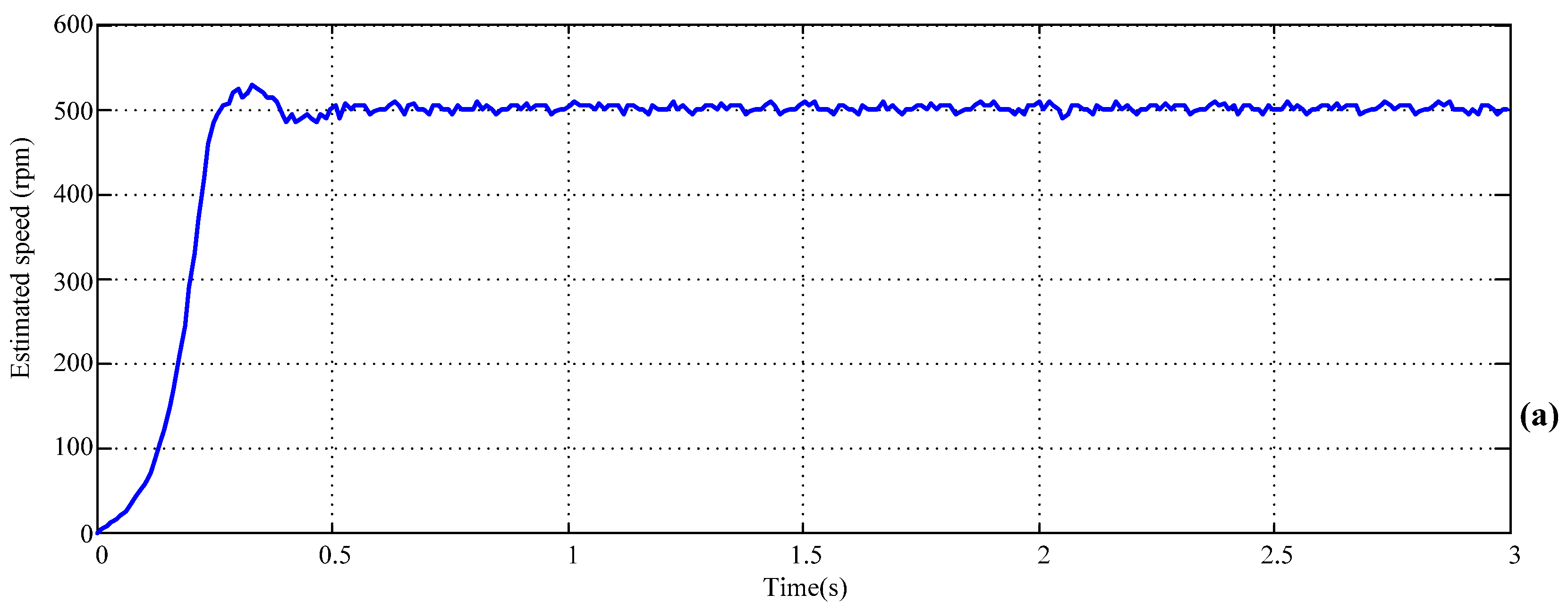
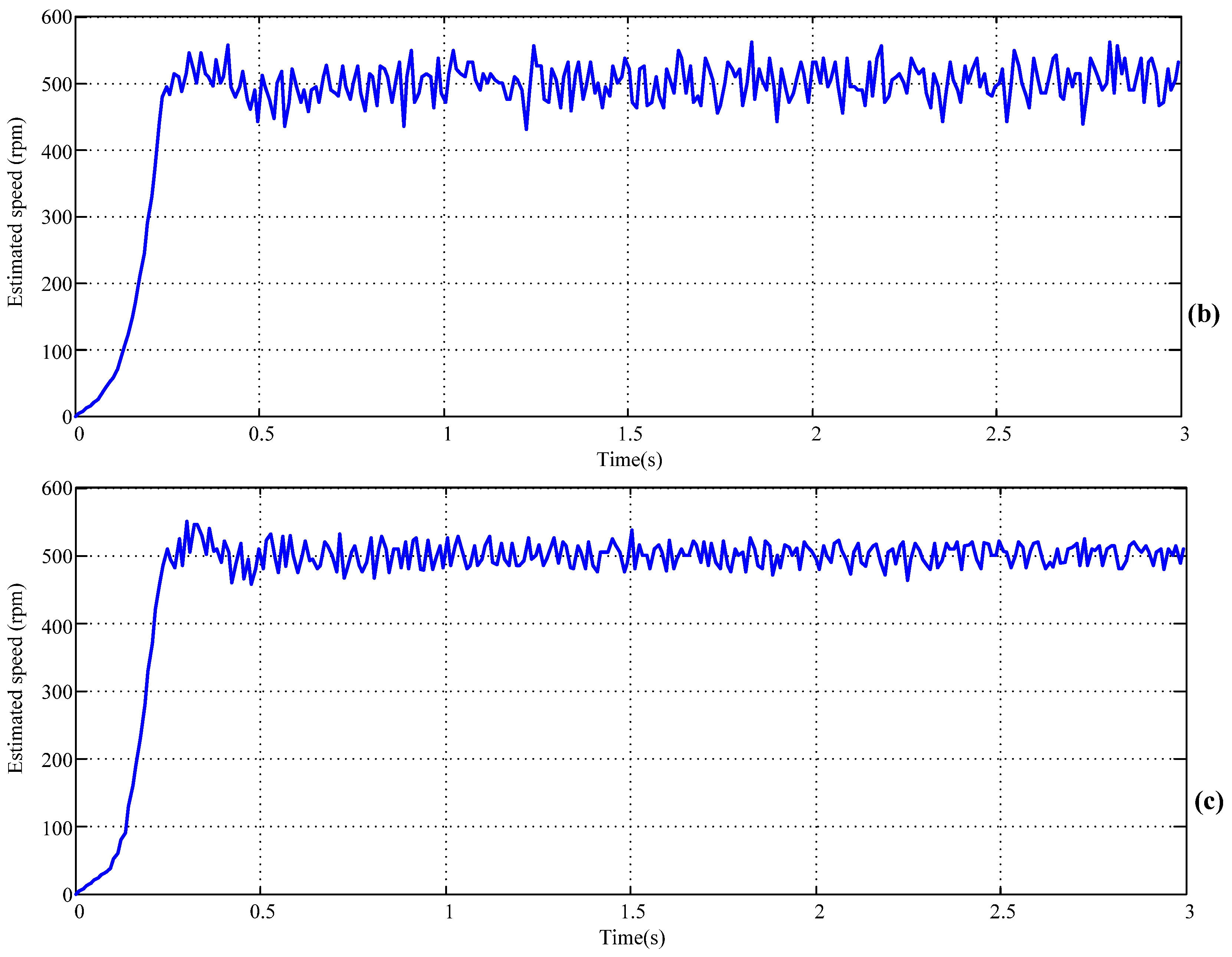
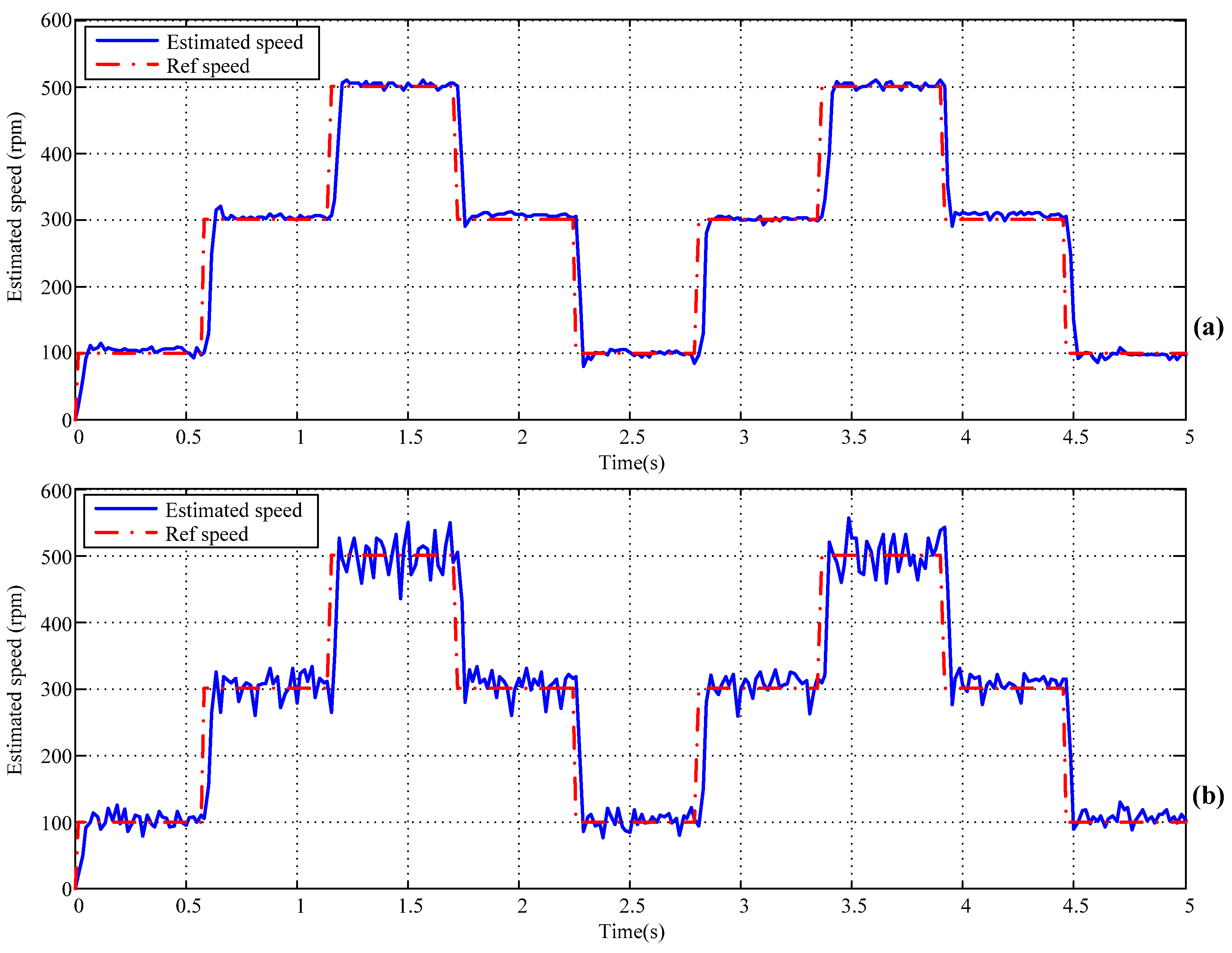
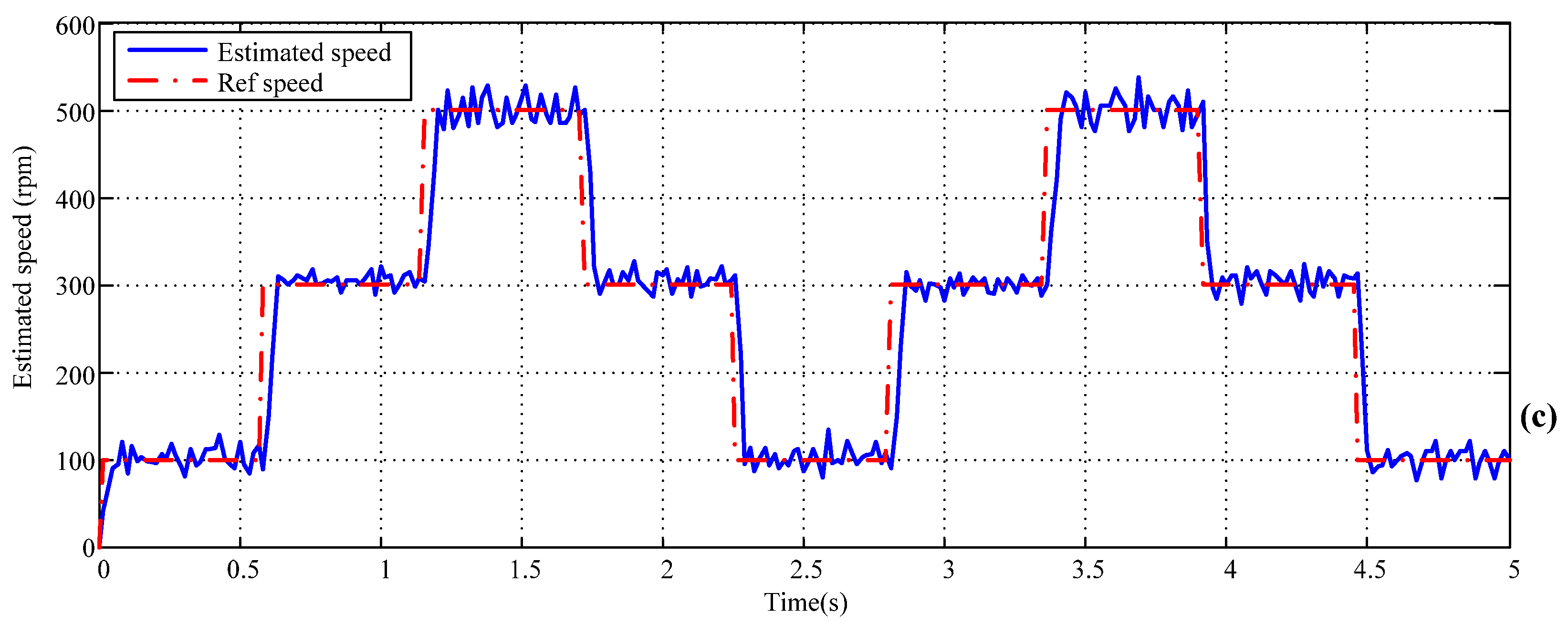
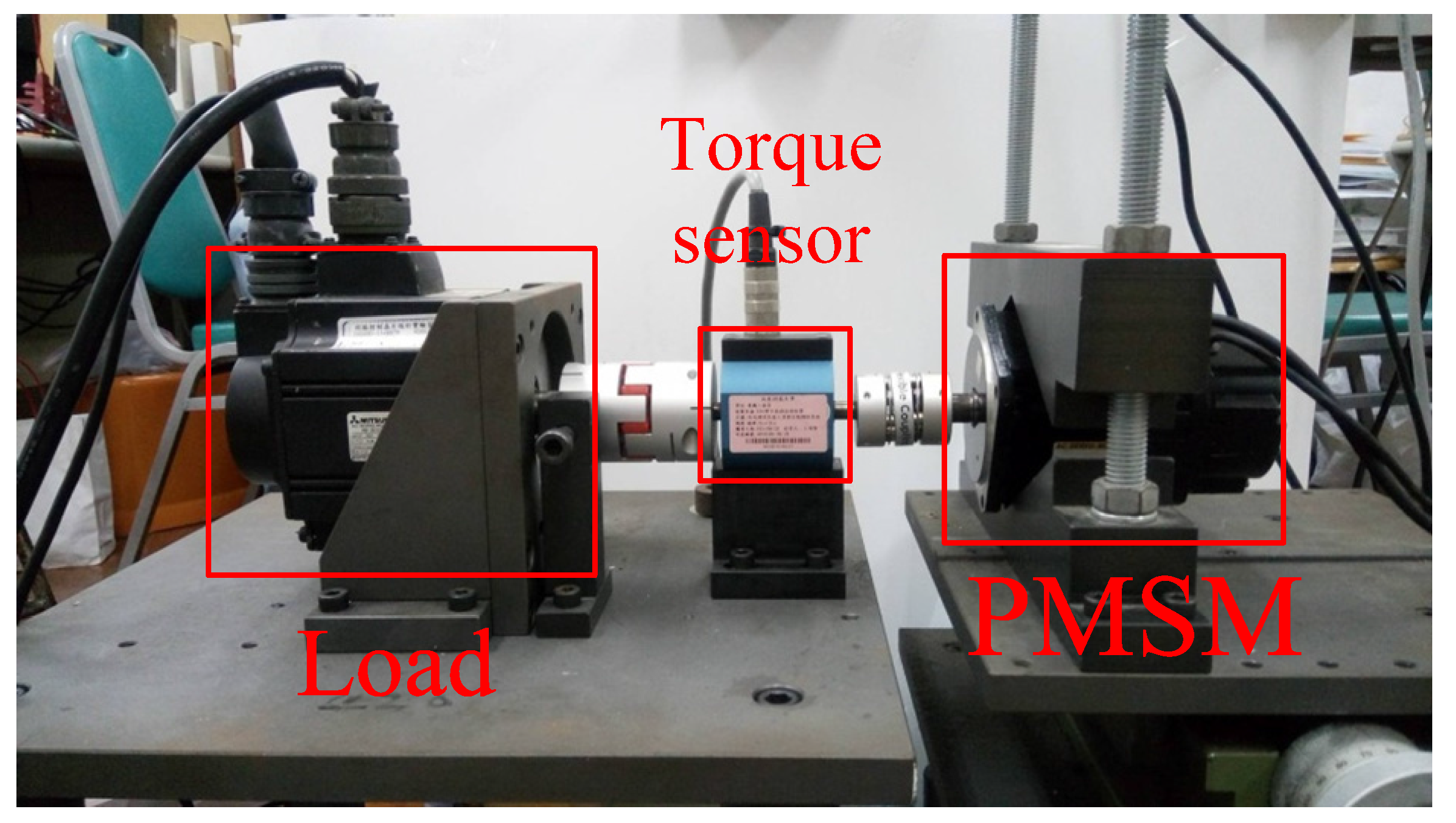
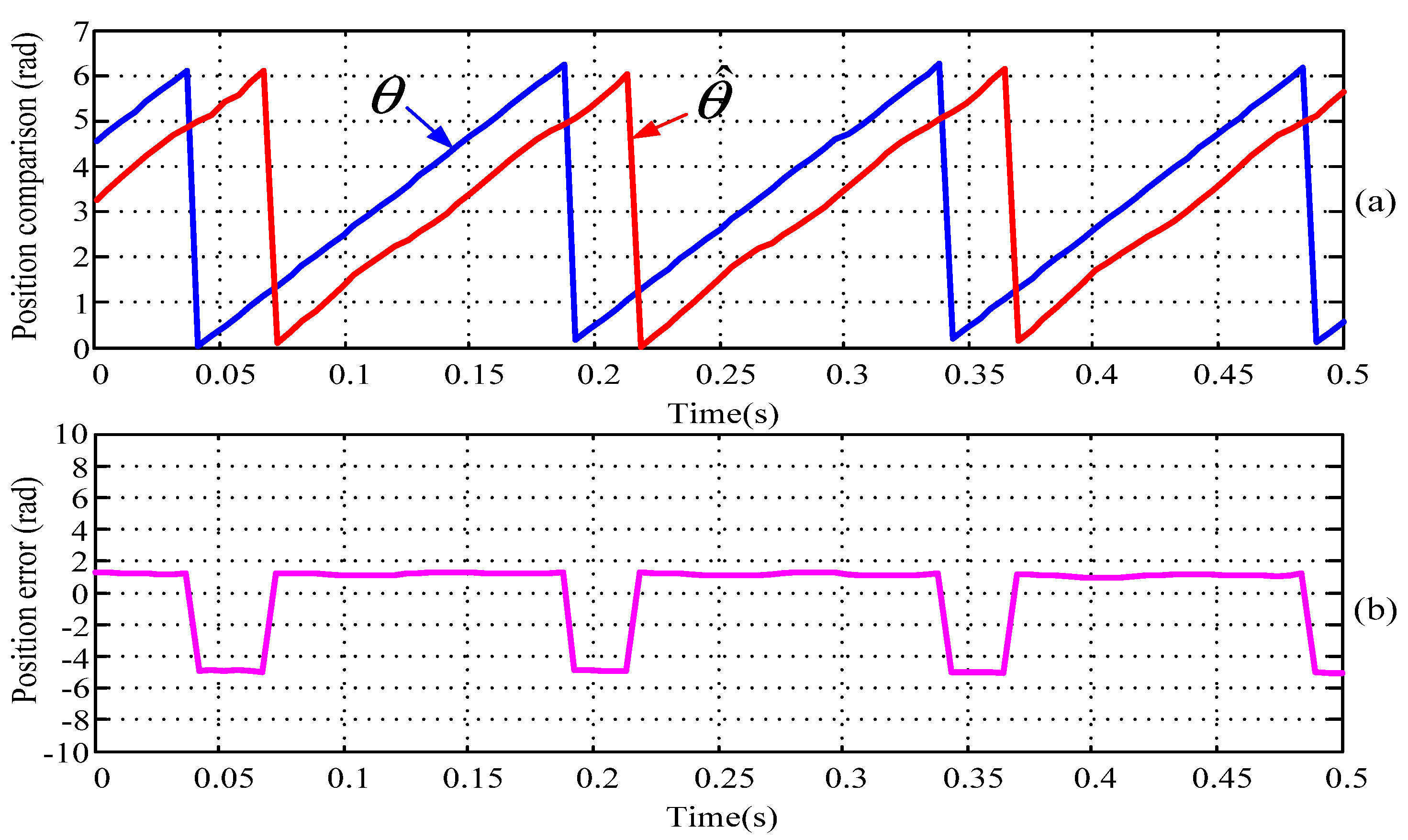
3. Simulation and Experimental Results

The simulation system with the parameters of PMSM 8CB75 listed in Table 1 is programmed by Matlab/Simulink. The activation functions with hyperbolic tangent sigmoid type in the hidden layers and linear transfer function in the output layer of the neural network are used. The neural network is trained by 100 rpm speed response and an encoder attached on the motor shaft. The values of these weights and biases are depicted as,
{ w 11 1 , w 12 1 , w 21 1 , w 22 1 , w 11 2 , w 12 2 , w 21 2 , w 22 2 } = { 0.840252 , 0.690252 , 0.0799998 , 0.200000 , 0.042868 , 0.19287 , 0.040042 , 0.029958 } { b 1 1 , b 2 1 , b 1 2 , b 2 2 } = { 1.049934 , 1.054758 , 0.033902 , 0.033902 }
The final absolute error of 1 × 10 3 is reached after 125 training epochs with learning rate of 0.5 for the neural network. The popular proportional-integral (PI) control is used in the speed and current control loops,
G x ( s ) = K x p ( 1 + K x i s ) ,
where the index x is s for speed or i for current loop. Based on the rule of thumb [30], the gains of speed control loop are K s p = 0.03 and K s i = 3 , and those for current control loop are K i p = 150 and K i i = 200 , respectively. These parameters are used in the simulations and experiments.
On simulation results, Figure 4a,b display the encoder output ( θ ) and rotor angle estimation ( θ ^ ) by ISMO, and the estimation error at the motor speed of 100 rpm, respectively. It is easy to find that the estimation lags encoder signal by almost 180 degrees. Similarly, Figure 5a,b display the encoder output and rotor angle estimation ( θ ^ ) by proposed ISMO and neural network (NN-ISMO), and the estimation error at the motor speed of 100 rpm, respectively. The maximum error is 0.007 radians and there is almost no lagging. The step speed responses of 100 rpm by ISMO and NN-ISMO are shown in Figure 6. Even with small overshoot and ringing, the response by NN-ISMO depicts the better performance.
The experimental setup is shown in Figure 7 and Figure 8. The setup in Figure 7 consists of the microcontroller dsPIC30F6010A and its programmer ICD3, PMSM, drive, current sensing circuit, and encoder signals for comparison. The dynamometer is shown in Figure 8. Figure 9, Figure 10, Figure 11 and Figure 12 display the results corresponding to simulations at speeds of 100 and 500 rpm and show the similar results. Figure 13 depicts the speed step responses of 500 rpm without loading by encoder (upper), ISMO, and NN-ISMO (bottom), respectively. With load of 2 Nm, slightly worse step responses of 500 rpm by encoder (upper), ISMO, and NN-ISMO (bottom), respectively, in Figure 14 are compared with those of Figure 13. Figure 15 shows the 0-100-300-500-300-100 step responses by encoder (upper), ISMO, and NN-ISMO (bottom), respectively. From the figures, it is easily proven that the proposed control algorithm show its validation and effectiveness.

4. Conclusions

This paper proposes an approach based on ISMO to first estimate the rotor position and neural networks to compensate the estimated position error due to small amplitudes of estimated back EMF for a sensorless PMSM control system that is able to improve both power consumption and speed response performance. The suggested ISMO adopts the concept of a multi-loop servo control system, and is applicable to many fields. The results of simulations and experiments show that the proposed control system is capable of estimating rotor angle to synchronize the original sensor outputs within acceptable limits and to improve motor speed responses for many applications.

Acknowledgments

The authors would like to thank Ministry of Science and Technology, Taiwan under contract Nos. of MOST 105-2221-E-218-017- and MOST 105-2218-E-218-002- for financial support.

Author Contributions

Ming-Shyan Wang conceived and designed the experiments; Tse-Ming Tsai performed the experiments; Ming-Shyan Wang and Tse-Ming Tsai analyzed the data; Ming-Shyan Wang contributed reagents, materials, and analytical tools; Ming-Shyan Wang wrote the paper.

Conflicts of Interest

The authors declare that there is no conflict of interests regarding the publication of this article.

References

  1. Energy-Efficiency Policy Opportunities for Electric Motor-Driven Systems. Available online: http://www.iea.org/publications/freepublications/publication/ee_for_electricsystems.pdf (accessed on 15 February 2017).
  2. Wu, R.; Slemon, G. A permanent magnet motor drive without a shaft sensor. IEEE Trans. Ind. Appl. 1991, 27, 1005–1011. [Google Scholar] [CrossRef]
  3. Rafaq, M.S.; Mwasilu, F.; Kim, J.; Choi, H.H.; Jung, J.-W. Online Parameter Identification for Model-Based Sensorless Control of Interior Permanent Magnet Synchronous Machine. IEEE Trans. Power Electron. 2017, 32, 4631–4643. [Google Scholar] [CrossRef]
  4. Piippo, A.; Hinkkanen, M.; Luomi, J. Sensorless control of PMSM drives using a combination of voltage model and HF signal injection. In Proceedings of the Conference Record of the 2004 IEEE Industry Applications Conference, 39th IAS Annual Meeting, Seattle, WA, USA, 3–7 October 2004; pp. 964–970. [Google Scholar]
  5. Liu, J.M.; Zhu, Z.Q. Novel sensorless control strategy with injection of high frequency pulsating carrier signal into stationary reference frame. IEEE Trans. Ind. Appl. 2013, 50, 2574–2583. [Google Scholar] [CrossRef]
  6. Zhu, Z.Q.; Gong, L.M. Investigation of effectiveness of sensorless operation in carrier-signal-injection-based sensorless-control methods. IEEE Trans. Ind. Electron. 2011, 58, 3431–3439. [Google Scholar] [CrossRef]
  7. Seilmeier, M.; Ebersberger, S.; Piepenbreier, B. HF Test Current Injection-Based Self-Sensing Control of PMSM for Low- and Zero-Speed Range Using Two-Degree-of-Freedom Current Control. IEEE Trans. Ind. Appl. 2015, 51, 2268–2278. [Google Scholar] [CrossRef]
  8. Moon, C.; Kwon, Y.A. Sensorless speed control of permanent magnet synchronous motor by unscented Kalman filter using various scaling parameters. J. Electr. Eng. Technol. 2016, 11, 347–352. [Google Scholar] [CrossRef]
  9. Tomei, P.; Verrelli, C.M. Observer-based speed tracking control for sensorless permanent magnet synchronous motors with unknown load torque. IEEE Trans. Autom. Control 2011, 56, 1484–1488. [Google Scholar] [CrossRef]
  10. Kim, H.; Son, J.; Lee, J. A high-speed sliding-mode observer for the sensorless speed control of a PMSM. IEEE Trans. Ind. Electron. 2011, 58, 4069–4077. [Google Scholar]
  11. Lee, H.; Lee, J. Design of Iterative Sliding Mode Observer for Sensorless PMSM Control. IEEE Trans. Control Syst. Technol. 2013, 21, 1394–1399. [Google Scholar] [CrossRef]
  12. Qiao, Z.; Shi, T.; Wang, Y.; Yan, Y.; Xia, C.; He, X. New Sliding-Mode Observer for Position Sensorless Control of Permanent-Magnet Synchronous Motor. IEEE Trans. Ind. Electron. 2013, 60, 710–719. [Google Scholar] [CrossRef]
  13. Chen, S.Y.; Liu, T.S. Intelligent tracking control of a PMLSM using self-evolving probabilistic fuzzy neural network. IET Electr. Power Appl. 2017, 11, 1043–1054. [Google Scholar] [CrossRef]
  14. Lin, F.J.; Sun, I.F.; Yang, K.J.; Chang, J.K. Recurrent Fuzzy Neural Cerebellar Model Articulation Network Fault-Tolerant Control of Six-Phase Permanent Magnet Synchronous Motor Position Servo Drive. IEEE Trans. Fuzzy Syst. 2016, 24, 153–167. [Google Scholar] [CrossRef]
  15. Sun, X.; Chen, L.; Jiang, H.; Yang, Z.; Chen, J.; Zhang, W. High-Performance Control for a Bearingless Permanent-Magnet Synchronous Motor Using Neural Network Inverse Scheme Plus Internal Model Controllers. IEEE Trans. Ind. Electron. 2016, 63, 3479–3488. [Google Scholar] [CrossRef]
  16. Liu, S.; Guo, X.; Zhang, L. Robust Adaptive Backstepping Sliding Mode Control for Six-Phase Permanent Magnet Synchronous Motor Using Recurrent Wavelet Fuzzy Neural Network. IEEE Access. 2017, 5, 14502–14515. [Google Scholar]
  17. Wang, M.S.; Syamsiana, I.N.; Lin, F.C. Sensorless Speed Control of Permanent Magnet Synchronous Motors by Neural Network Algorithm. Math. Probl. Eng. 2014. [Google Scholar] [CrossRef]
  18. Schimmack, M.; Feistauer, E.E.; Amancio-Filhoand, S.T.; Mercorelli, P. Hysteresis Analysis and Control of a Metal-Polymer Hybrid Soft Actuator. Energies 2017, 10, 508. [Google Scholar] [CrossRef]
  19. Ginoya, D.; Shendge, P.D.; Phadke, S.B. Sliding Mode Control for Mismatched Uncertain Systems Using an Extended Disturbance Observer. IEEE Trans. Ind. Electron. 2014, 61, 1983–1992. [Google Scholar] [CrossRef]
  20. Chaudhari, P.; Sharma, V.; Shendge, P.D.; Phadke, S.B. Disturbance observer based sliding mode control for anti-lock braking system. In Proceedings of the IEEE International Conference on Power Electronics, Intelligent Control and Energy Systems (ICPEICES), Delhi, India, 4–6 July 2016; pp. 1–5. [Google Scholar]
  21. Haus, B.; Mercorelli, P.; Werner, N. A Robust Adaptive Self-tuning Sliding Mode Control for a Hybrid Actuator in Camless Internal Combustion Engines. In Advances and Applications in Sliding Mode Control Systems; Azar, A.T., Zhu, Q., Eds.; Springer International Publishing: Cham, Switzerland, 2015; pp. 107–136. [Google Scholar]
  22. Veluvolu, K.C.; Soh, Y.C. High-Gain Observers with Sliding Mode for State and Unknown Input Estimations. IEEE Trans. Ind. Electron. 2009, 56, 3386–3393. [Google Scholar] [CrossRef]
  23. Mercorelli, P. An Anti-Saturating Adaptive Pre-action and a Slide Surface to Achieve Soft Landing Control for Electromagnetic Actuators. IEEE/ASME Trans. Mechatron. 2012, 17, 76–85. [Google Scholar] [CrossRef]
  24. Mercorelli, P. A Two-Stage Sliding-Mode High-Gain Observer to Reduce Uncertainties and Disturbances Effects for Sensorless Control in Automotive Applications. IEEE Trans. Ind. Electron. 2015, 62, 5929–5940. [Google Scholar] [CrossRef]
  25. Su, Y.; Zheng, C.; Mercorelli, P. Global Finite-Time Stabilization of Planar Linear Systems with Actuator Saturation. IEEE Trans. Circuits Syst. II Express Briefs 2017, 8, 947–951. [Google Scholar] [CrossRef]
  26. Antonio, L.M.; Hugo, V.B.; Josep, M.B.-M.; Javier, M.-A.; Luis, M.-S. Sliding-mode-control-based boost converter for high-voltage-low-power applications. IEEE Trans. Ind. Electron. 2015, 62, 229–237. [Google Scholar]
  27. Biricik, S.; Komurcugil, H. Optimized sliding mode control to maximize existence region for single-phase dynamic voltage restorers. IEEE Trans. Ind. Inform. 2016, 12, 1486–1497. [Google Scholar] [CrossRef]
  28. Pisano, A.; Tanelli, M.; Ferrara, A. Switched/time-based adaptation for second-order sliding mode control. Automatica 2016, 64, 126–132. [Google Scholar] [CrossRef]
  29. Precup, R.E.; Radac, M.B.; Roman, R.C.; Petriu, E.M. Model-free sliding mode control of nonlinear systems: Algorithms and experiments. Inf. Sci. 2017, 381, 176–192. [Google Scholar] [CrossRef]
  30. Ellis, G. Control System Design Guide, 2nd ed.; Academic Press: San Diego, CA, USA, 2000; pp. 105–106. ISBN 2-12-237465-7. [Google Scholar]
Figure 1. The block diagram of the proposed sensorless permanent magnet synchronous motor (PMSM) control system.
Energies 10 01780 g001
Figure 2. The block diagram of iterative sliding mode observer.
Energies 10 01780 g002
Figure 3. The artificial neural network.
Energies 10 01780 g003
Figure 4. The rotor angle at the motor speed of 100 rpm (a) encoder output ( θ ) and rotor angle estimation ( θ ^ ) by iterative sliding mode observer (ISMO), and (b) the estimation error.
Energies 10 01780 g004
Figure 5. The rotor angle at the motor speed of 100 rpm (a) encoder output ( θ ) and rotor angle estimation ( θ ^ ) by NN-ISMO, and (b) the estimation error.
Energies 10 01780 g005
Figure 6. The step speed responses of 100 rpm by (a) ISMO and (b) NN-ISMO.
Energies 10 01780 g006
Figure 7. The experimental setup.
Energies 10 01780 g007
Figure 8. Dynamometer.
Energies 10 01780 g008
Figure 9. The rotor angle at the motor speed of 100 rpm (a) encoder output ( θ ) and rotor angle estimation ( θ ^ ) by ISMO, and (b) the estimation error.
Energies 10 01780 g009
Figure 10. The rotor angle at the motor speed of 100 rpm (a) encoder output ( θ ) and rotor angle estimation ( θ ^ ) by NN-ISMO, and (b) the estimation error.
Energies 10 01780 g010
Figure 11. The rotor angle at the motor speed of 500 rpm (a) encoder output ( θ ) and rotor angle estimation ( θ ^ ) by ISMO, and (b) the estimation error.
Energies 10 01780 g011
Figure 12. The rotor angle at the motor speed of 500 rpm (a) encoder output ( θ ) and rotor angle estimation ( θ ^ ) by NN-ISMO, and (b) the estimation error.
Energies 10 01780 g012
Figure 13. The step speed responses of 500 rpm without loading by (a) encoder, (b) ISMO, and (c) NN-ISMO, respectively.
Energies 10 01780 g013
Figure 14. The step speed responses of 500 rpm with loading of 2 Nm by (a) encoder, (b) ISMO, and (c) NN-ISMO, respectively.
Energies 10 01780 g014aEnergies 10 01780 g014b
Figure 15. The speed step responses of 0-100-300-500-300-100 rpm with loading of 2 Nm by (a) encoder, (b) ISMO, and (c) NN-ISMO, respectively.
Energies 10 01780 g015aEnergies 10 01780 g015b
Table 1. Parameters of PMSM Sinano 8CB75.
ParametersUnitValue
PW750
VV149.4
TN·m2.931
IA3.4
NRpm3000
KN·m/A0.776
JKg·cm22.449
Rs3.27
LsmH10.2

