Article

Energy-Saving Benefits of Adiabatic Humidification in the Air Conditioning Systems of Semiconductor Cleanrooms

Department of Architectural Engineering, College of Engineering, Hanyang University, 222 Wangsimni-Ro, Seongdong-Gu, Seoul 04763, Korea
*
Author to whom correspondence should be addressed.
Energies 2017, 10(11), 1774; https://doi.org/10.3390/en10111774
Submission received: 5 October 2017 / Revised: 31 October 2017 / Accepted: 1 November 2017 / Published: 3 November 2017

Abstract

:
This paper aimed to evaluate the applicability of adiabatic humidification in the heating, ventilation, and air conditioning (HVAC) systems of semiconductor cleanrooms. Accurate temperature and humidity control are essential in semiconductor cleanrooms and high energy consumption steam humidification is commonly used. Therefore, we propose an adiabatic humidification system employing a pressurized water atomizer to reduce the energy consumption. The annual energy consumption of three different HVAC systems were analyzed to evaluate the applicability of adiabatic humidification. The studied cases were as follows: (1) CASE 1: a make-up air unit (MAU) with a steam humidifier, a dry cooling coil (DCC), and a fan filter unit (FFU); (2) CASE 2: a MAU with the pressurized water atomizer, a DCC, and a FFU; and (3) CASE 3: a MAU, a DCC, and a FFU, and the pressurized water atomizer installed in the return duct. The energy saving potential of adiabatic humidification over steam humidification has been proved, with savings of 8% and 23% in CASE 2 and CASE 3 compared to CASE 1, respectively. Furthermore, the pressurized water atomizer installed in the return duct exhibits greater energy saving effect than when installed in the MAU.

1. Introduction

Cleanrooms are special spaces that maintain the controlled environments required for the manufacture of certain products [1]. In most cleanrooms, ISO standards for cleanliness are applied depending, on the size of the particles that affect the products [2]. To maintain a specified cleanliness level, the concentration of airborne particles and microorganisms in the air are controlled to within a target set-point. In addition, cleanrooms require precise control of environmental conditions such as temperature, humidity, and pressure, depending on the production requirements of the particular products [3,4].
In large-scale industrial cleanrooms that have high energy demands, such as semiconductor fabrication plants, a large amount of outdoor air is introduced into the cleanroom to maintain cleanliness and a positive pressure [
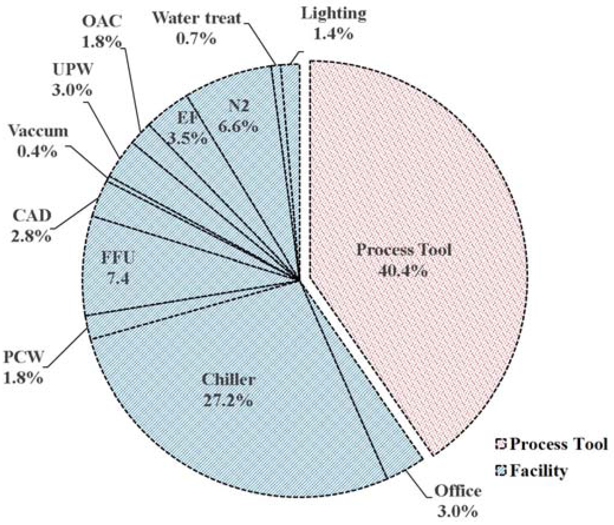
5]. As shown in Figure 1, generally, the energy consumed in the facility systems (e.g., air conditioning system, nitrogen plant, lighting and water treatment components) is approximately 60% of the total energy consumption in semiconductor cleanrooms and the rest is used by the tools for making semiconductor products [6].
Maintaining a constant environment at 23 °C and 45% relative humidity throughout the year, 24 h a day, is essential in cleanrooms because semiconductors are very sensitive to electrostatic problems. In addition, due to the high heating load generated by the manufacturing tools and fans, the energy consumption of HVAC systems such as chilled water systems, make-up air systems, exhaust air systems, process cooling water systems and ultra-pure water systems is very large. As a result, the cooling capacities of HVAC systems in semiconductor cleanrooms are much larger than those of common commercial buildings [5]. Therefore, according to the Semiconductor Equipment and Materials International (SEMI) website [7], the energy conservation of HVAC systems for semiconductor cleanrooms is one of the top priorities in the semiconductor industry.
Much research on energy savings for HVAC systems applied in semiconductor cleanrooms has been conducted. Brown [8] confirmed the energy-saving effects of an energy recovery method applied in the MAU for five climatic conditions. Hu and Tsao [9] compared the energy performance of five HVAC systems in semiconductor cleanrooms and found that the HVAC system that consisted of a FFU, a DCC, and a MAU consumed the least energy as compared to the other HVAC systems. Tsao and Hu [10] analyzed the energy consumption of systems of various component arrangements such as cooling coil, heating coil, preheating coil and fan in the MAU. Suzuki et al. [11] improved the cooling performance of MAUs in high-tech fabrication plants by increasing the condensation efficiency of the cooling coil resulting in a 3% energy saving compared with conventional MAUs. Lin and Hu [12] suggested a Fan Dry Coil Unit (FDCU) system that has a higher particle removal efficiency and a low energy consumption rate as compared to existing HVAC systems. Hunt et al. [13] investigated the effects of fan efficiency on the overall operational cost of cleanrooms. Hu et al. [14] compared the performance and energy consumption of cleanrooms with axial fans and FFUs using computational fluid dynamics.
Most of the previous studies were conducted with a focus on reducing the energy consumption of HVAC systems in semiconductor cleanrooms by improving the cooling performance of the MAU as well as the fan efficiency. When the outdoor air is very dry and cold in the winter, conventional HVAC systems may use steam as the humidification method to maintain the humidity of the cleanroom constant. However, using steam is energy intensive due to the large amount of energy required to generate the steam [15]. In contrast to the conventional humidification method using steam, adiabatic humidification methods using water are a suitable alternative. In addition, like direct evaporative coolers, adiabatic humidification methods using water have an additional cooling effect due to evaporation. A variety of applications of adiabatic humidification have been used to control the temperature and humidity in the environment [16]. Evaluations of the applicability of adiabatic humidification in greenhouses, indoor poultry farms, and textile-spinning mills have also been conducted [17,18,19,20,21,22,23,24,25,26,27,28,29]. However, few studies has been conducted on the applicability of adiabatic humidification in semiconductor cleanrooms. Recent studies on humidification methods for cleanrooms are as follows: Tsao and Hu [20] compared the pump and fan energy requirements of four different humidification methods in the MAU, including wet media, direct water atomization, steam and two-phase flow. According to the simulation results, direct water atomization was the most suitable method to be applied in the MAU because the pump energy required was lower than that of other humidification methods. In addition, this method had a smaller required installation area. Chen et al. [21] also demonstrated the feasibility and energy saving effects of two adiabatic humidification methods—one using a high-pressure water atomizer and the other using two fluids—through experiment and simulation of adiabatic humidification methods applied in the return duct and MAU for semiconductor cleanrooms. According to the results, adiabatic humidification systems exhibited a 75% reduction in energy consumption as compared to conventional humidification methods using steam. The high-pressure water atomizer consumed less energy as compared to humidification systems using two fluids. Also the results of experiment showed that adiabatic humidification systems using the high-pressure water atomizer kept the cleanroom at target relative humidity level within ±5%. Therefore, adiabatic humidification systems maintained the stable relative humidity level in semiconductor cleanrooms.
However, in the previous studies, only conveyance energy which was consumed for humidifying the process air was estimated, such as for a fan and pump, instead of the total operating energy consumption of the air conditioning systems. Furthermore, none of the above studies presented a theoretical estimation of the annual energy consumption of total HVAC systems and evaporative cooling effect of adiabatic humidification in semiconductor cleanrooms in terms of the various humidification methods. Therefore, in this paper, with the aim of reducing the humidification energy requirements and maintaining stable humidity levels in cleanrooms, an adiabatic humidification method is proposed as an alternative to conventional steam humidifiers. To evaluate the applicability of the adiabatic humidification method in HVAC system for semiconductor cleanrooms, the annual operating energy consumption and processes of three HVAC systems using different humidification methods were compared and analyzed as case studies.

2. Humidification Methods

There are two typical methods for humidification: isothermal and adiabatic. These methods are the most commonly used in commercial and industrial humidification for maintaining set-point humidity levels in their operating zones [22]. Isothermal humidification, which generates steam vapor from external energy, injects steam directly into the air. In adiabatic humidification, the air is in direct contact with water, which is not heated. Table 1, which is an extract from the ASHRAE (American Society of Heating, Refrigerating, and Air-Conditioning Engineers) handbook [23], shows various systems for each humidification method. Isothermal humidification methods can be classified according to the heat exchanging method and the external energy used to produce the steam vapor, as shown in Table 1. Adiabatic humidification is divided into atomization and evaporation methods. In the evaporation method, the air is humidified as it passes through the wetted media. In the atomization method, the water as the form of mist is physically atomized into the air. Atomizers are classified into four types: ultrasonic, centrifugal, pressurized-water, and compressed air atomizers.
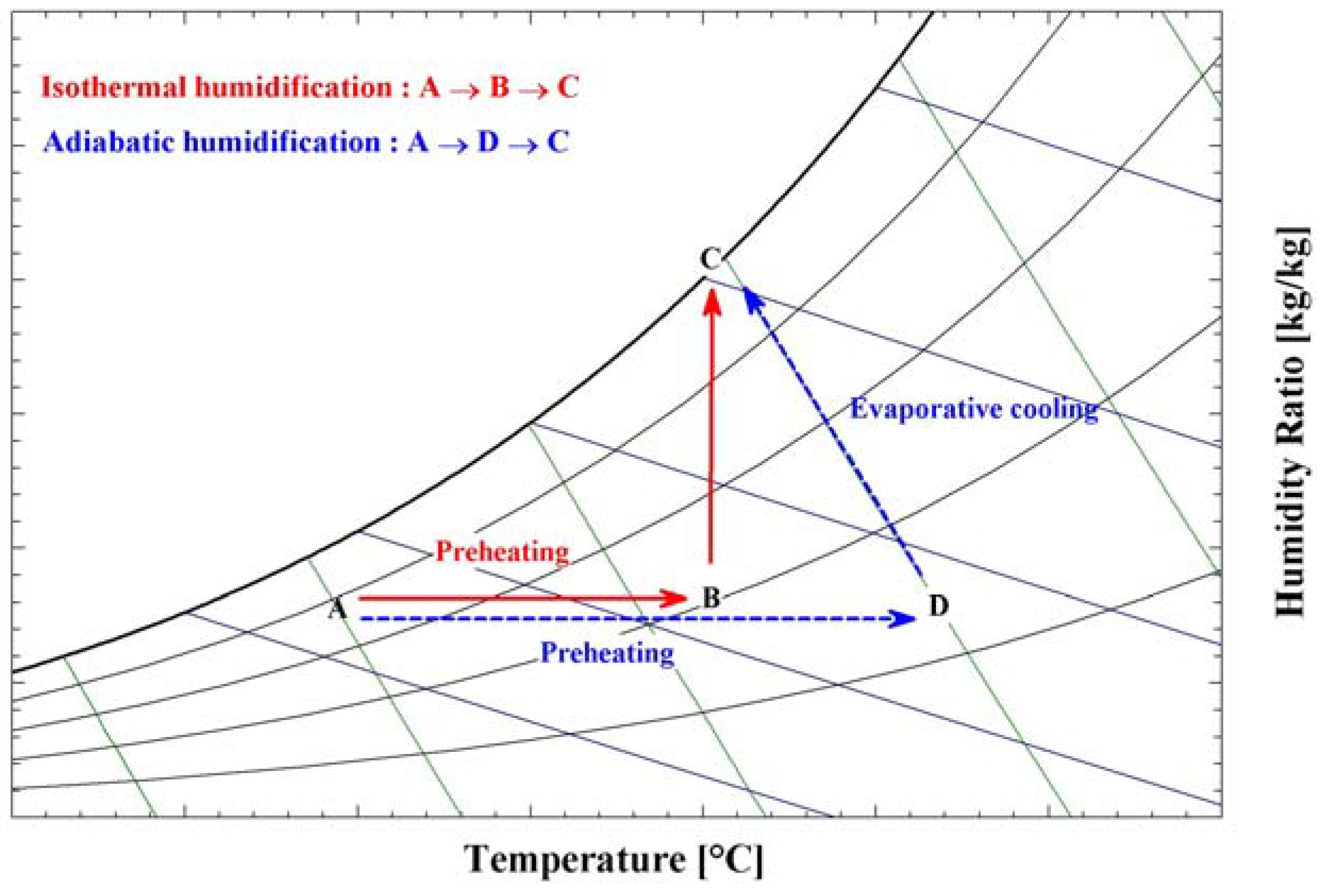
In the case of isothermal humidification using water vapor, the humidification process exhibits an almost vertical line on the psychrometric diagram. However, in adiabatic humidification, the air is humidified till the saturation curve along the isenthalpic line or the wet bulb temperature line [15]. In addition, in this process, the air is humidified and cooled simultaneously through evaporative cooling. A diagram of the psychrometric process for both methods is shown in Figure 2. To humidify the air to the set-point condition, the air follows the path from D to C for adiabatic humidification and from B to C for isothermal humidification. As seen in Figure 2, the air is to be heated by external energy before humidification for both isothermal and adiabatic humidification from A to B and from A to D, respectively.
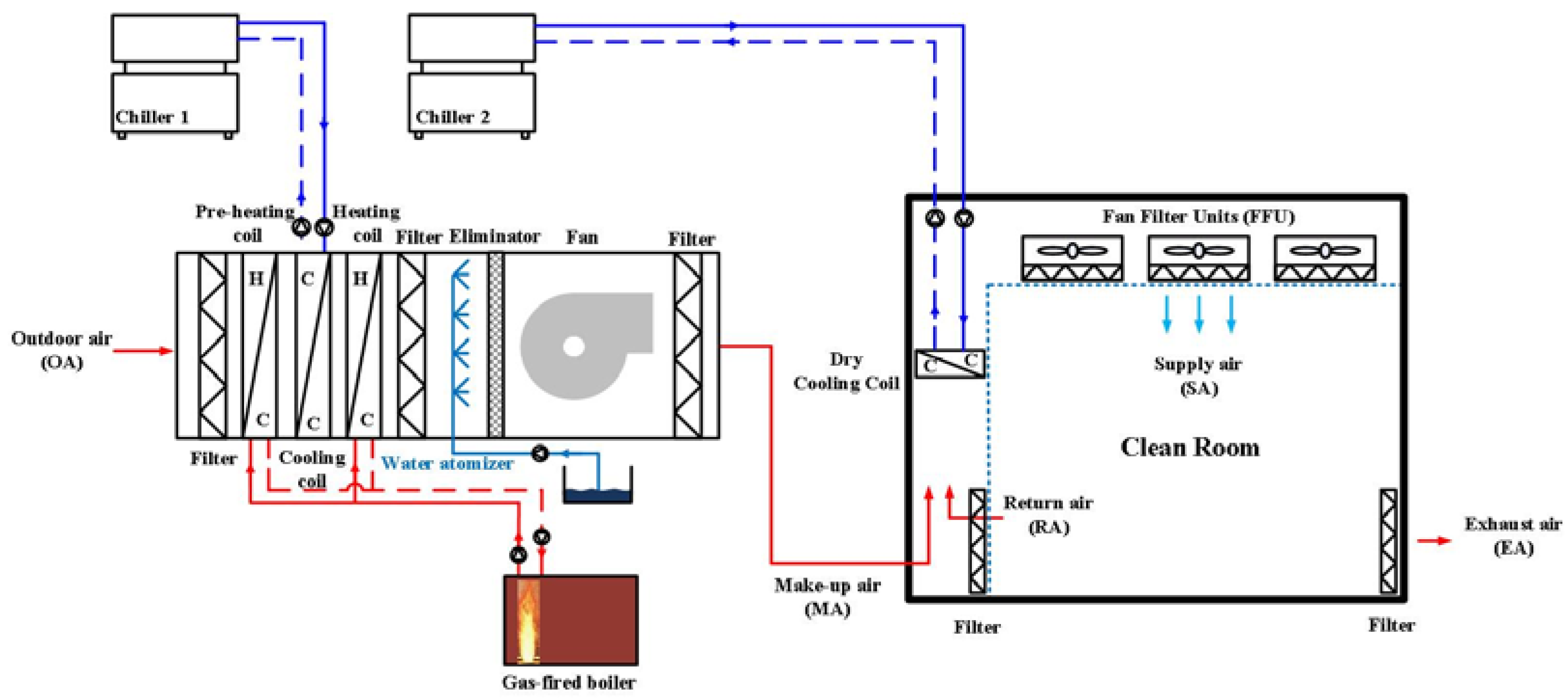
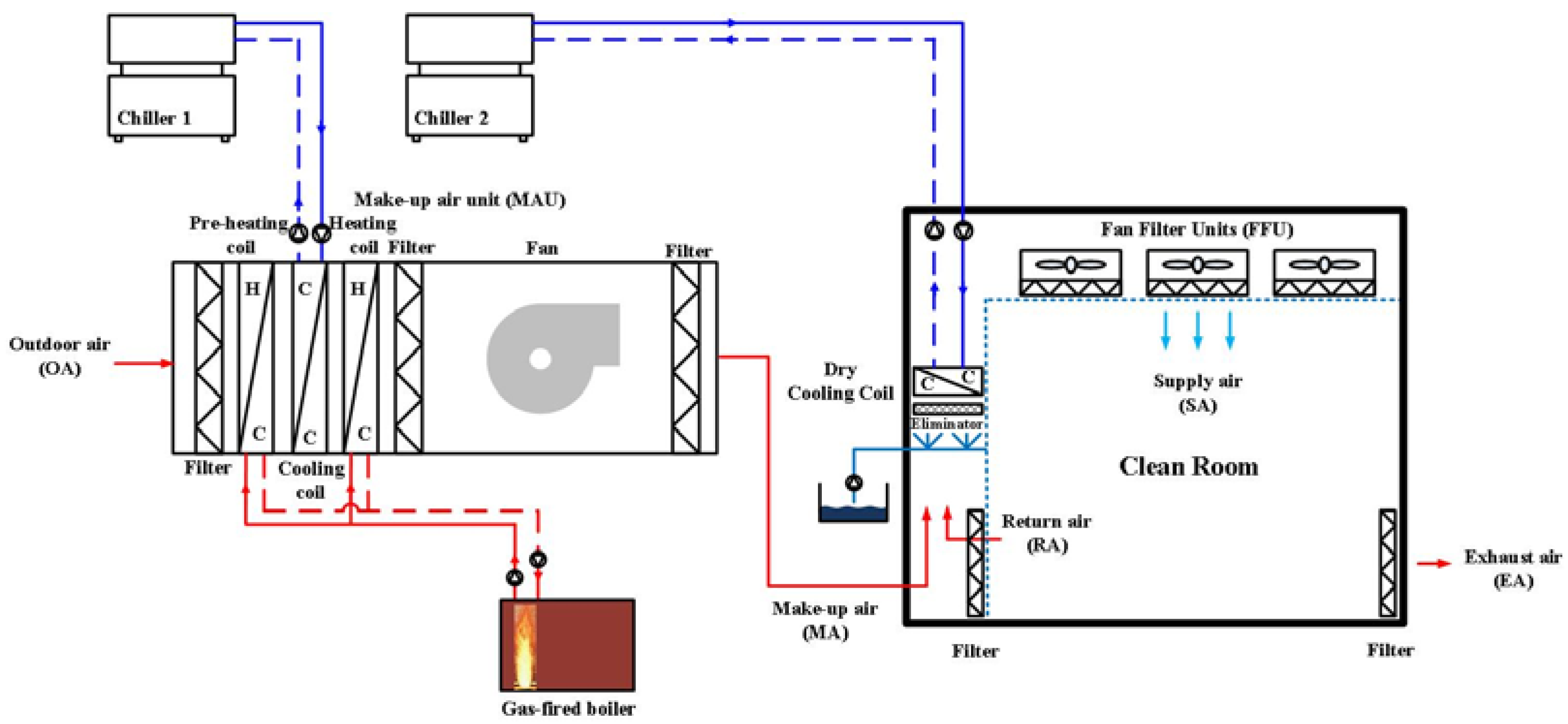
In semiconductor cleanrooms, suitable humidification and dehumidification are necessary to prevent electrostatic problems for the semiconductor products. Generally, when supplying outdoor air to the cleanroom for ventilation, a MAU humidifies or dehumidifies the air depending on the outdoor air to maintain the set-point humidity of the cleanroom [10]. For humidification of cleanroom, ultra-purified water (UWP) would be ideal for avoiding pollution in cleanrooms. However, electrode-type steam humidifiers cannot be applied in the cleanroom as isothermal humidification due to very-low conductivity of UWP [20]. Instead, in semiconductor cleanrooms, direct-injection steam humidifiers that use steam from a boiler are commonly used. Meanwhile, when applying adiabatic humidification to HVAC systems of semiconductor cleanrooms, the size of the water droplets (e.g., 5–50 μm) and the ability to meet the humidification demands are essential for precise humidity control [15,21,24]. However, evaporative adiabatic humidification methods using wetted media, centrifugal, and ultrasonic humidification methods are not suitable for large spaces such as semiconductor cleanrooms because either the size of the water droplets sprayed by those systems is too large or the humidification capacity of the system is not sufficient [20,24]. Therefore, among the adiabatic humidification methods, the pressurized water and compressed air atomizers using a nozzle are the most suitable for maintaining the humidity in semiconductor cleanrooms. According to previous research [20,21], compressed air atomizers are considered to be unsuitable for cleanroom application because of the large amount of energy consumed for humidification compared to the pressurized water atomizer. Therefore, in this study, to evaluate the applicability of adiabatic humidification in cleanroom HVAC systems, the pressurized water atomizer and the direct-injection steam humidifier are employed.

3. Case Description and Overview

3.1. Cleanroom Design

The thermal load of a semiconductor cleanroom is simulated to analyze and compare the total operating energy consumption of the HVAC system applied depending on the humidification method employed. A large cooling load is generated over the entire year due to the large amount of heat generated from the production equipment and fans [25]. The properties of the semiconductor fab are assumed based on the research of Hu et al. [9] because the cleanroom operating parameters are different according to manufacturing process. Additionally, the semiconductor fab is assumed to be located in Seoul, Korea, and is simulated with Seoul weather data of the International Weather for Energy Calculations (IWEC) files [26] offered by ASHRAE. In this paper, the HVAC system is one consisting of an MAU, DCC, and FFU, which is known as an energy conservative system [6,12]. A draw-through type MAU adjusts the outdoor air conditions to maintain the set-point conditions of the fab. Then the supply air coming from the MAU is mixed with the indoor recirculated air in the return duct. The mixture is cooled by the DCC in order to meet the cooling load demand of the fab. In addition, the FFU has a high efficiency filter function that keeps the air flowing in a constant direction to minimize the recirculation of dust particles generated in the indoor. Table 2 lists the properties of the semiconductor fab simulated in this study.

3.2. Steam Humidification in the HVAC System (CASE 1: Base Reference Case)

Direct-injection steam humidifiers are the most commonly used method for humidification in semiconductor cleanrooms. CASE 1, which is considered as a reference case in this research, consists of an HVAC system with a direct-injection steam humidifier installed in the MAU. As shown in Figure 3, the MAU consists of a preheating coil, cooling coil, heating coil and direct-injection steam humidifier in series with the DCC and FFU installed in the return duct. Additionally, a boiler and pump are needed to generate and supply the steam and hot water for each direct-injection steam humidifier and preheating coil. Chillers supplying low temperature chilled water (at 6 °C) to the cooling coil in the MAU and high temperature chilled water (at 14 °C) to the DCC are used in CASE 1. It is assumed that 10 MAUs capable of supplying a 100,000 m3/h airflow and a total of 7270 FFUs capable of supplying a 900 m3/h airflow are used to maintain the set-point condition of the semiconductor cleanroom [9].

3.3. Adiabatic Humidification in the HVAC System (CASE 2: Pressurized Water Atomizer in the MAU)

For CASE 2, the direct-injection steam humidifier in CASE 1 is substituted by a pressurized water atomizer for the adiabatic humidification method (Figure 4). According to the research of Chaker et al. [27], pressurized water atomizers are composed of a high-pressure pump and pin nozzle for humidification. The water is ejected from the orifice at a high velocity using a high-pressure pump that then collides with the pin nozzle resulting in the water being atomized into the air as a thin conical sheet of water [28]. Also, when used in the MAU, the pressurized water atomizer injects the water in the form of fine water droplets (of 10 μm diameters) into the air because the droplets must evaporate before passing through the fan of MAU [9]. The pressurized water atomizer does not need the boiler for generating the steam vapor when humidifying the air to achieve same humidification performance of the system used in CASE 1 [21]. Figure 4 shows the configuration of the HVAC system for CASE 2. The components of the MAU for CASE 2 are arranged in the following order: first is the preheating coil followed by the cooling coil, heating coil, and pressurized water atomizer. To humidify the air while simultaneously preventing dehumidification by the cooling coil, the pressurized water atomizer is placed towards the downstream end in the MAU (i.e., after the cooling coil). Additionally, an eliminator is required in the MAU to prevent the water from scattering. Like CASE 1, a boiler for supplying hot water to preheating coil is required for humidification. Low and high temperature chillers are used to supply chilled water (at 6 °C and 14 °C, respectively) to the cooling coil and DCC, which are installed in the return duct, for dehumidification and sensible cooling, respectively. There are 10 MAUs and a set of 7270 FFUs, with each unit having an airflow capacity of 100,000 m3/h and 900 m3/h, respectively.

3.4. Adiabatic Humidification in the HVAC System (CASE 3: Pressurized Water Atomizer in the Return Duct)

In CASE 3, to humidify the air, the pressurized water atomizer is installed in the return duct (Figure 5). The size of the water droplets and evaporation time (t) are important because complete evaporation of the water droplets is necessary before entering the FFU. In CASE 2 with the pressurized water atomizer installed in the MAU, the time required for evaporation is very short resulting in the water being sprayed as very fine water droplets (i.e., having diameters of 10 μm). However, CASE 3 allows for larger droplet sizes because of the longer evaporation time available for humidification. The evaporation time (t) with respect to the diameter of the water droplet ( d p ) for complete evaporation is calculated by Equation (1) using the temperature ( T I ) and vapor pressure ( P l ) of the airstream [29]. Also, given a diffusion coefficient ( D o ) of 0.22 m2/s at a water droplet temperature of 0 °C, the diffusion coefficient of the water droplet required to calculate the evaporation time is estimated by Equation (2).
t = ρ p × R × d p 2 8 × D × M × ( P d T d P I T I )
D D 0 × ( T d T I ) 1.94
when the pressurized water atomizer is installed in the return duct, the required size of sprayed water droplet is 40 μm, assuming that the distance from the nozzle of the pressurized water atomizer to the FFU is 6 m and that the air velocity in the return duct is 3 m/s. In addition, it is confirmed that the pressurized water atomizer has the same performance as in CASE 2 regardless of the DCC position [21]. Therefore, in CASE 3, the pressurized water atomizer is assumed to be installed before the DCC in the return duct in order to reduce the load on the DCC by evaporative cooling. An eliminator is installed before the DCC to prevent water scattering when using a pressurized water atomizer system.

3.5. Operating Mode of Each Case

The operating mode of the three cleanroom HVAC systems differ from case to case. Each case has three operating modes depending on the outdoor air conditions (Figure 6, Figure 7 and Figure 8). Using a psychrometric chart, the operating modes are divided with respect to the regions requiring dehumidification (Region A) and humidification (Regions B and C). In Region A, the humidity of the outdoor air is higher than the set-point humidity of the supply air (i.e., the set-point humidity of the cleanroom). The three cases operate in the same process using the cooling coil and electric heating coil for dehumidifying and reheating in Region A. On the other hand, when the humidification of the outdoor air is required for ventilation, each case has a different operating process due to the humidification method and the position of the humidifier (i.e., Regions B and C). Table 3 presents the supply air conditions in the MAU. The operating processes of each case are as follows:
  • Region A: In Region A, with hot and humid air, all cases operate identically. Thus, the cooling and heating coils are used to dehumidify the outdoor air up to a supply humidity set-point without operating the humidifier. Therefore, the air after passing through the MAU has a temperature of 12 °C and a relative humidity of 90%. The supplied air through the MAU and the indoor recirculated air are mixed in the return duct and then sensibly cooled by the DCC to meet the cooling load of the cleanroom. Finally, the cooled air after being treated by the DCC is supplied to the cleanroom by the FFU.
  • Region B: In Region B, a humidification device is required in order to humidify the outdoor air up to the set-point humidity ratio. In CASE 1, the air is cooled or heated by cooling or heating coils to maintain the set-point supply air conditions (12 °C DB, 90% RH) because the humidification process using the steam humidifier is an isothermal process, as shown in the psychrometric chart in Figure 6a. The air is passed through the MAU and treated using the DCC. The air is then supplied to the clean room by the FFU similar to as in the Region A operation. As shown in Figure 7b and Figure 8b, CASE 2 and CASE 3 uses the pressurized water atomizer in the MAU and return duct, respectively, for humidification instead of a direct-injection steam humidifier. In the psychrometric chart, the humidification process is an adiabatic process, the process through the pressurized water atomizer follows a constant wet-bulb temperature line. In CASE 2, the supply air temperature is not constant at the set-point values due to pressurized water atomizer being installed downstream of the MAU. Therefore, depending on the amount of water required for humidification, the cooled air from the evaporative cooling process is mixed with the recirculated air in the return duct and then sensibly cooled by the DCC in order to meet the cooling load of the cleanroom. However, in CASE 3, since the MAU does not have a humidifier, the MAU only controls the air temperature supplied to it from the return duct. The air supplied from the MAU mixes with the recirculated air in the return duct while the pressurized water atomizer operates to maintain the set-point humidity ratio of the cleanroom. If the cooling effect on the air due to the adiabatic humidification cannot meet the indoor cooling load, the DCC will activate to maintain the set-point temperature of the cleanroom (Figure 8b).
  • Region C: During the winter season, the outdoor air is very dry and cold. Therefore, to humidify the process air to the set-point humidity condition, it is necessary to heat the outdoor air using a preheating coil before passing it through the humidifier. In CASE 1, it is necessary to preheat the outdoor air with a heating coil up to the dew point temperature (10.3 °C) of the supply air set-point. Therefore, the outdoor air is first heated to the dew point temperature of the cleanroom by the preheating coil and then humidified by the direct-injection steam humidifier in the MAU. Then, the air is supplied to the cleanroom through the DCC and FFU in order to maintain the set-point environment of the cleanroom. In CASE 2, which uses a pressurized water atomizer installed in the MAU, the preheating coil activates once the temperature of the outdoor air was too low. When humidifying using a pressurized water atomizer, more preheating coil load is generated than in CASE 1 because the air is humidified along the wet bulb temperature line of the humidifier line in the psychometric chart. The air supplied from the MAU is mixed with the recirculation air in the return duct and the DCC operates depending on the cooling load of the cleanroom. Finally, the pressurized water atomizer is installed upstream of the DCC in the return duct such that only the MAU controls the temperature of the process air in order to meet the MAU set-point temperature, just as in CASE 1. As a result, the preheating load is identical to that in CASE 1 because the recirculation air is mixed with the air supplied from the MAU in the return duct. Then the pressurized water atomizer installed upstream of the DCC activates to humidify the air supplied to the cleanroom in order to maintain the set-point humidity ratio of the cleanroom. When operating the pressurized water atomizer, the air temperature is decreased by the cooling effect of the adiabatic humidification. If the resulting evaporative cooled air cannot meet the cooling load of the cleanroom, the DCC then activates.

4. Simulation Methodology

4.1. Cleanroom Load Calculation

Table 4 shows the detailed operating conditions of an actual semiconductor cleanroom in operation as well as the calculation method used to determine the cooling load of the cleanroom [9]. Since the latent load of the cleanroom is very small compared to the sensible load, the latent heat loads are generally not considered in the cooling load of the cleanroom (i.e., SHF 100%, (sensible heat factor)). As shown in Equation (3), the cooling load of the cleanroom is influenced by lighting, occupancy, the environment surrounding the cleanroom, the heat generated by the FFU, and the equipment that are operating 24 h a day. Additionally, the cooling effects of the process cooling water (PCW) and the polluted exhaust air generated in the semiconductor manufacturing process are considered as adding to the cooling load. Equation (4) shows the DCC load that is calculated by taking into account the cooling load of the cleanroom and cooling effect of the air supplied to the cleanroom from the MAU:
l o a d C R = Q ˙ F a n + Q ˙ L i g h t i n g + Q ˙ O c c u p a n t + Q ˙ e n v e l o p e d + Q ˙ e q u i p m e n t Q ˙ P C W Q ˙ E A
Q ˙ D C C = l o a d C R Q ˙ M A U

4.2. MAU Load Calculation

The load of the MAU is divided into three parts; the preheating, cooling, and heating coil loads. The airflow rate ( M ˙ a i r ) is assumed as a steady-state condition to estimate coil load. Therefore, the energy balance of each coil is written as per Equation (5). The load at each coil is calculated according to Δ h , which is the enthalpy difference between the inlet and outlet sides of the air, as well as the air flow rate of the MAU. Also, the humidification or dehumidification rate ( M ˙ H u m ) is calculated as per Equation (6). These values are determined using the humidity ratio difference ( Δ W ) between the air entering the humidifier and the set-point humidity ratio as well as the airflow rate through the humidifier.
Q ˙ C o i l = M ˙ a i r × Δ h
M ˙ H u m = M ˙ a i r × Δ W

4.3. Humidification System

The humidification methods used in this study are a pressurized water atomizer and a direct-injection steam humidifier. These methods control the humidity of the cleanroom by humidifying the air according to the humidification rate obtained from Equation (6).
The required amount of water ( M ˙ s t e a m w a t e r ) with the direct-injection steam humidifier is calculated by dividing amount of humidification estimated with Equation (6) by the humidification efficiency ( ε h u m . s t e a m ), as shown in Equation (7) [22]. The load of the gas-fired boiler ( Q ˙ s t e a m b o i l e r ) needed for producing the required steam can be expressed by Equation (8) using the change in temperature and the latent heat of vaporization of water. Therefore, the energy consumption for producing steam with the gas-fired boiler is calculated using Equations (9)–(11) using the part load ratio (PLR) of the steam boiler and the efficiency ( ε s t e a m b o i l e r . a c t u a l ) [31]. To inject the steam generated from the gas-fired boiler into the air using the manifold, the feed water (e.g., ultra-pure water (UPW)) is supplied to the gas-fired boiler at the proper pressure (i.e., 1.2 MPa) from the feed tank [20]. Therefore, the energy consumption of the feed water pump ( W ˙ B F P ), which supplies the feed water to the gas-fired boiler, is calculated using Equation (8). Table 5 shows the operating scheme of the humidification method.
M ˙ s t e a m w a t e r = M ˙ H u m ε h u m . s t e a m
Q ˙ s t e a m b o i l e r = M ˙ s t e a m w a t e r × ( C P . w a t e r × ( T b o i l i n g . w T i n l e t . w ) + h v a p o r i z a t i o n )
P L R s t e a m b o i l e r = Q ˙ s t e a m b o i l e r C a p a c i t y   o f   s t e a m b o i l e r
ε s t e a m b o i l e r . a c t u a l = ε s t e a m b o i l e r . r a t e d × P L R s t e a m b o i l e r
W ˙ s t e a m b o i l e r = Q ˙ s t e a m b o i l e r ε s t e a m b o i l e r . a c t u a l
W ˙ B F P = M ˙ s t e a m w a t e r × ( Δ P B F P ) ε B F P
In this study, the pressurized water atomizer uses an impaction pin nozzle with a diameter of about 0.152 mm and a high-pressure pump [28]. To calculate the necessary water consumption rate for humidification in the water atomizer ( M ˙ a t o m i z e r w a t e r ), the amount of water required in CASE 2 and 3 are calculated by dividing Equation (6) by the humidification efficiency of the pressurized water atomizer ( ε h u m . a t o m i z e r ), as shown in Equation (13) [22]. CASE 2, which uses a pressurized water atomizer installed in the MAU, requires very small water droplets. In this case, the size of the water droplet to be sprayed with the pressurized water atomizer located inside the MAU is 10 μm in diameter [20]. To achieve this size, an injection pressure of 21 MPa is set in the high-pressure pump, per nozzle, when the air is humidified by using a water atomizer with a pin nozzle [28]. On the other hand, the size of the water droplet required in CASE 3 where the water atomizer is installed in the return duct is calculated to be 40 μm using Equations (1) and (2). In addition, an injection pressure of 7 MPa in the high-pressure pump per nozzle is required for a droplet size of 40 μm [21,28]. To control the amount of the water required for humidification, the number of nozzles operating in accordance with the humidification quantity is controlled as on-off. The operating energy of the high-pressure pump in the pressurized water atomizer is estimated using the pressure drop of the circulating water from the water tank to the pin nozzle ( Δ P s y s t e m ), the pressure drop required from the pin nozzle ( Δ P A ), total water flow rate for humidification ( M ˙ W A ), and the efficiency of the high-pressure pump ( ε W A P ), as shown in Equations (13)–(15):
M ˙ W A = M ˙ H u m ε h u m . a t o m i z e r
W ˙ W A P d e s i g n = M ˙ W A d e s i g n × ( Δ P W A P + Δ P s y s t e m ) ε W A P
W ˙ W A P = W ˙ W A P d e s i g n × ( W ˙ A W W ˙ A W d e s i g n ) 3

4.4. Analysis of Remaining System Components

A chiller and boiler are used to handle loads of the DCC ( Q ˙ D C C ), cooling coil ( Q ˙ C C ), and preheating coil ( Q ˙ P H C ) as per Equation (5). An electric heating coil is used in this simulation to represent the load of the heating coil, ( Q ˙ H C ). To calculate the chiller energy consumption, a low temperature chiller model is used for cooling and dehumidifying in the cooling coil and a high temperature chiller model is used for sensible cooling in the DCC, as per DOE-2.1 (from the Department Of Energy) provided by Energy Plus [31]. Equations (16)–(18) describe three performance curves, cooling capacity function of the temperature curve (CAPFT), energy input to the cooling output ratio function of the temperature curve (EIRFT), and energy input to the cooling output ratio function of the part load ratio curve (EIRFPLR), which are used to calculate the energy consumption of chillers. CAPFT (Equation (16)) and EIRFT (Equation (17)) represent the maximum cooling capacity and the full-load efficiency of the chiller with respect to the temperatures of the evaporator and the condenser, respectively. The part-load efficiency of the chiller is expressed with EIRFPLR (Equation (18)). The part load ratio (PLR) and power input of the chiller is calculated with Equations (19) and (20), respectively. Table 6 shows the low and high temperature chiller operating scheme [9]:
CAPFT = 1.052729 + 0.037507 × T C W S + 0.0002294 × T C W S 2 0.003213844 × T O A 0.0001016 × T O A 2 0.0005399 × T C W S × T O A
EIRFT = 0.5363279857 0.0099693061 × T C W S + 0.0004111273 × T C W S 2 + 0.0041571647 × T O A + 0.0004088049 × T O A 2 0.0005399259 × T C W S × T O A
EIRFPLR = 0.0354 + 0.7233 × PLR + 0.2472 × PLR 2
PLR = Q ˙ C C ( o r   Q ˙ D C C ) C a p a c i t y   o f   c h i l l e r · CAPFT
W ˙ c h i l l e r = W r e f × CAPFT × EIRFT × EIRFPLR
The hot-water boiler model from Energy plus [31] is used to acquire the preheating coil load in the MAU. The actual efficiency of the gas-fired boiler ( ε B o i l e r . a c t u a l ) is determined using the PLR of the boiler ( P L R b o i l e r ) from Equations (21) and (22). In this study, a condensing boiler, which has a higher efficiency than conventional gas-fired boilers, is used. Therefore, the energy consumption of the gas-fired boiler is calculated using Equation (23). Table 7 shows the scheme of the gas-fired boiler. Additionally, for treating the load of the heating coil, the energy of an electric heater is estimated using Equation (24):
P L R b o i l e r = Q ˙ P H C C a p a c i t y   o f   b o i l e r
ε B o i l e r . a c t u a l = ε B o i l e r . r a t e d × P L R b o i l e r
W ˙ b o i l e r = Q ˙ P H C ε B o i l e r . a c t u a l
W ˙ e l e c t r i c = Q ˙ H C
The energy consumed by the fans in the MAU and FFU are determined using Equations (25) and (26) with the constant volume flow rate of the air ( V ˙ M A U a i r , V ˙ a i r ), pressure drops ( Δ P f a n , Δ P F F U ), and fan efficiencies ( ε f a n = 0.8, ε F F U = 0.8). The pump energy needed to supply the chilled and hot water is determined using Equation (27) with the volume flow rate of the water ( V ˙ w a t e r ) and the pressure drop ( Δ P p u m p ) and the efficiency ( ε p u m p ) of the pump. Table 8 shows the efficiency of fan as well as the pressure drop for the each component in this simulation:
W ˙ f a n = ( V ˙ M A U a i r × Δ P f a n ) ε f a n
W ˙ F F U = ( V ˙ a i r × Δ P F F U ) ε F F U
V ˙ p u m p = ( V ˙ w a t e r × Δ P p u m p ) ε p u m p

5. Simulation Results and Discussion

5.1. Cleanroom Load Simulation

The cooling load of the semiconductor cleanroom is simulated using a transient system simulation tool (TRNSYS 17) [35] and the energy consumption of different HVAC systems in operation are evaluated using a commercial engineering equation solver (EES) [36]. 
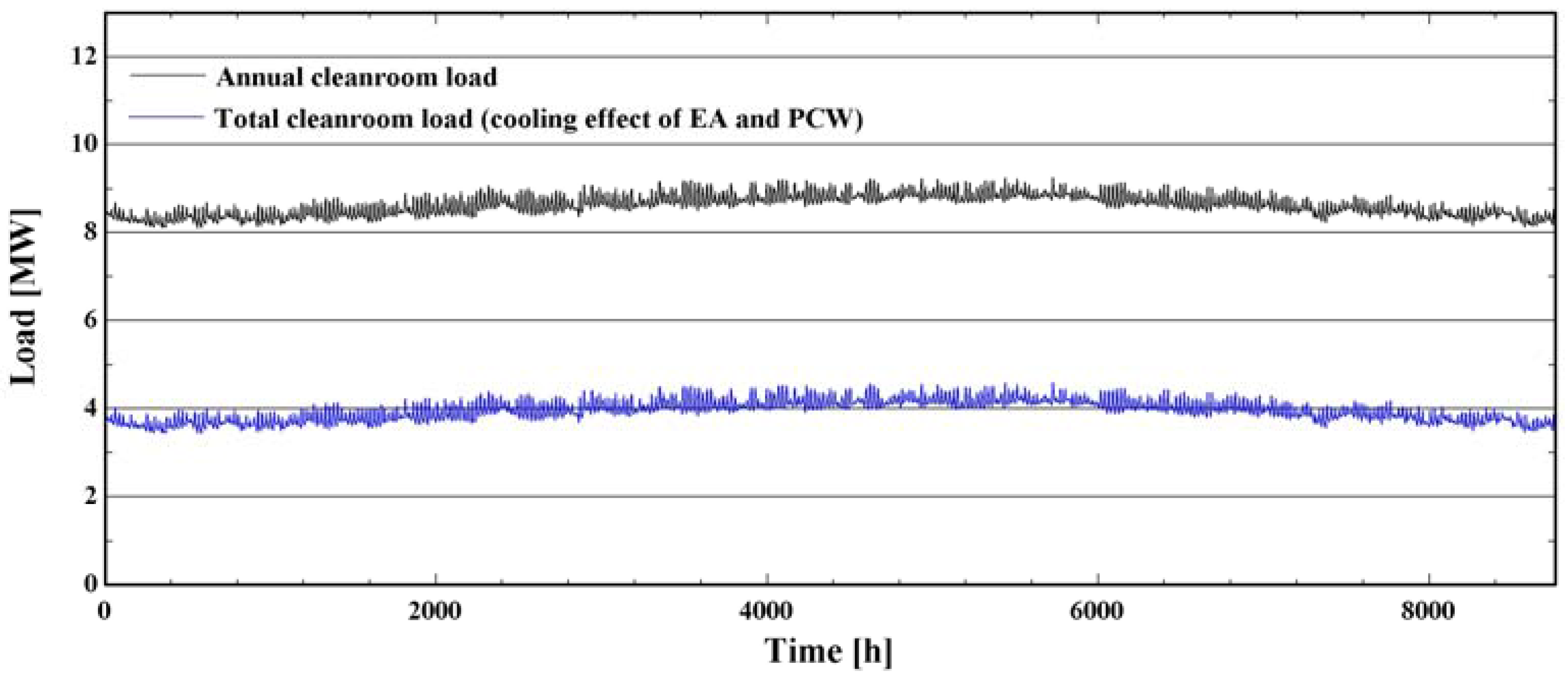
Figure 9 shows the annual cooling load of the cleanroom according to Seoul weather data from IWEC. Due to the large heating load generated by the equipment and fan, the HVAC system operates for treating the cooling load all year round to maintain the set-point air condition in the cleanroom. In Figure 9, the black lines represent the total cooling load of the cleanroom while the blue lines represent the cooling load of that considering the cooling effects of the exhaust air and the PCW. According to the results, and considering the cooling effects of the exhaust air and the PCW, the cooling load of the semiconductor cleanroom is reduced by about 50%, resulting in a load similar to that expressed by the blue line.

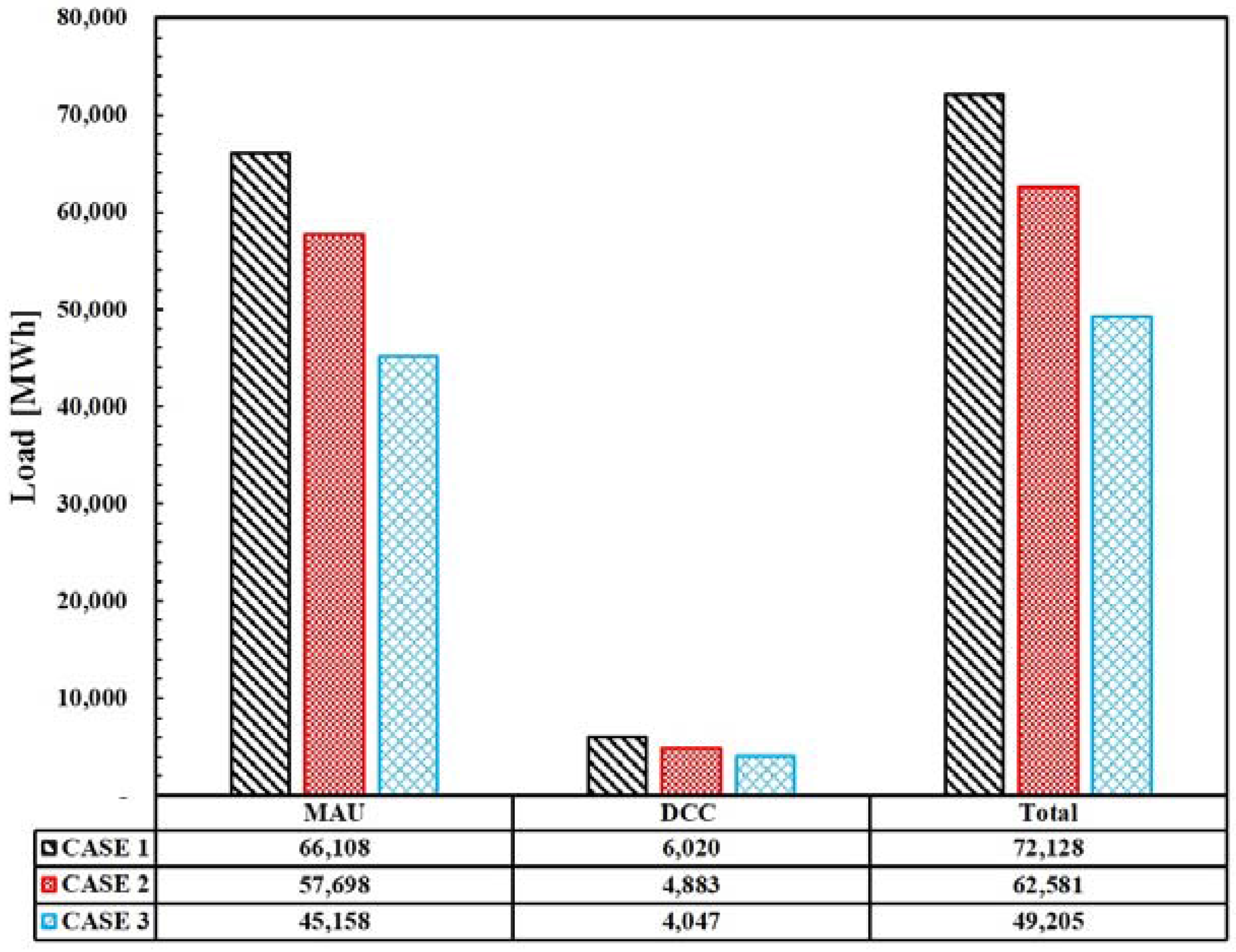
5.2. Comparison of the Case Loads

Figure 10 and 
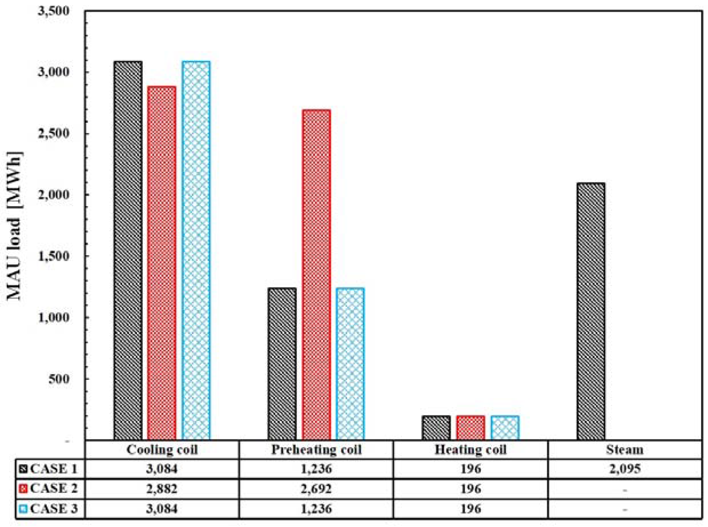
Figure 11 show the annual operating load in the MAUs and in the overall HVAC system. The operating load of each MAU is sub-divided by the loads on the cooling, preheating, electric heating coils as well as by the steam load for humidification.
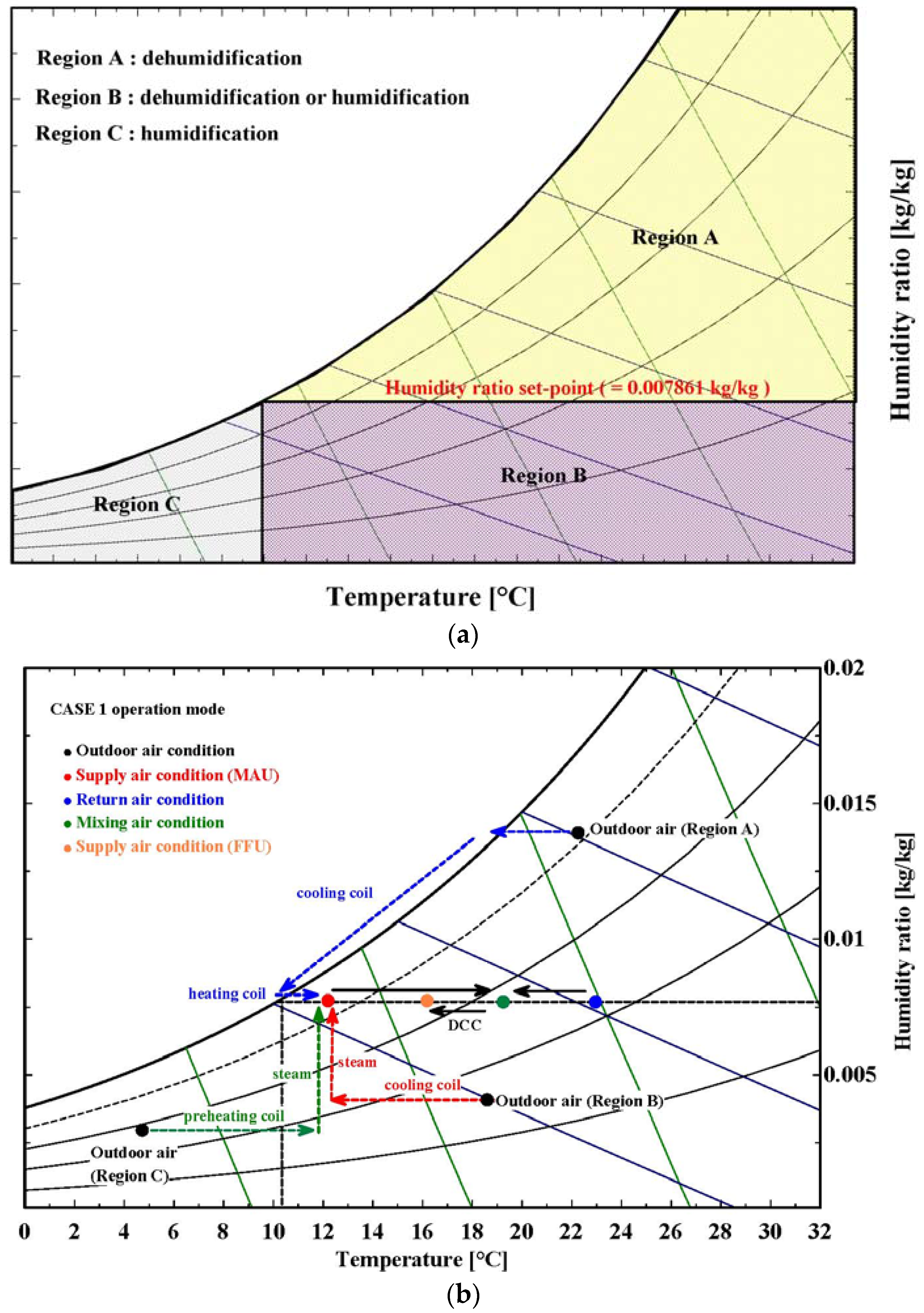
The cooling coil operates when the outdoor air needs to be dehumidified and cooled (i.e., Regions A and B). When the outdoor air conditions are included in Region A, the cooling coil load for all three cases is identical. For CASE 2, if the outdoor air conditions are included in Region B, only the pressurized water atomizer installed downstream of MAU operates in humidification without operating the cooling coil. Therefore, the cooling coil load in CASE 2 is decreased by 7% as compared to other cases.
The electric heating coil is used to prevent the overcooling of the air when dehumidifying the outdoor air with the cooling coil. For that reason, the coil only operates in Region A. Therefore, the load on the electric heating coil is identical for all cases due to operating processes of the three cases being equivalent.
On the other hand, the steam humidification load generated in CASE 1 with the direct-injection steam humidifier is not present in CASE 2 and 3, which uses a pressurized water atomizer Therefore, in CASE 1 exhibits the highest steam load of all the cases for humidification.
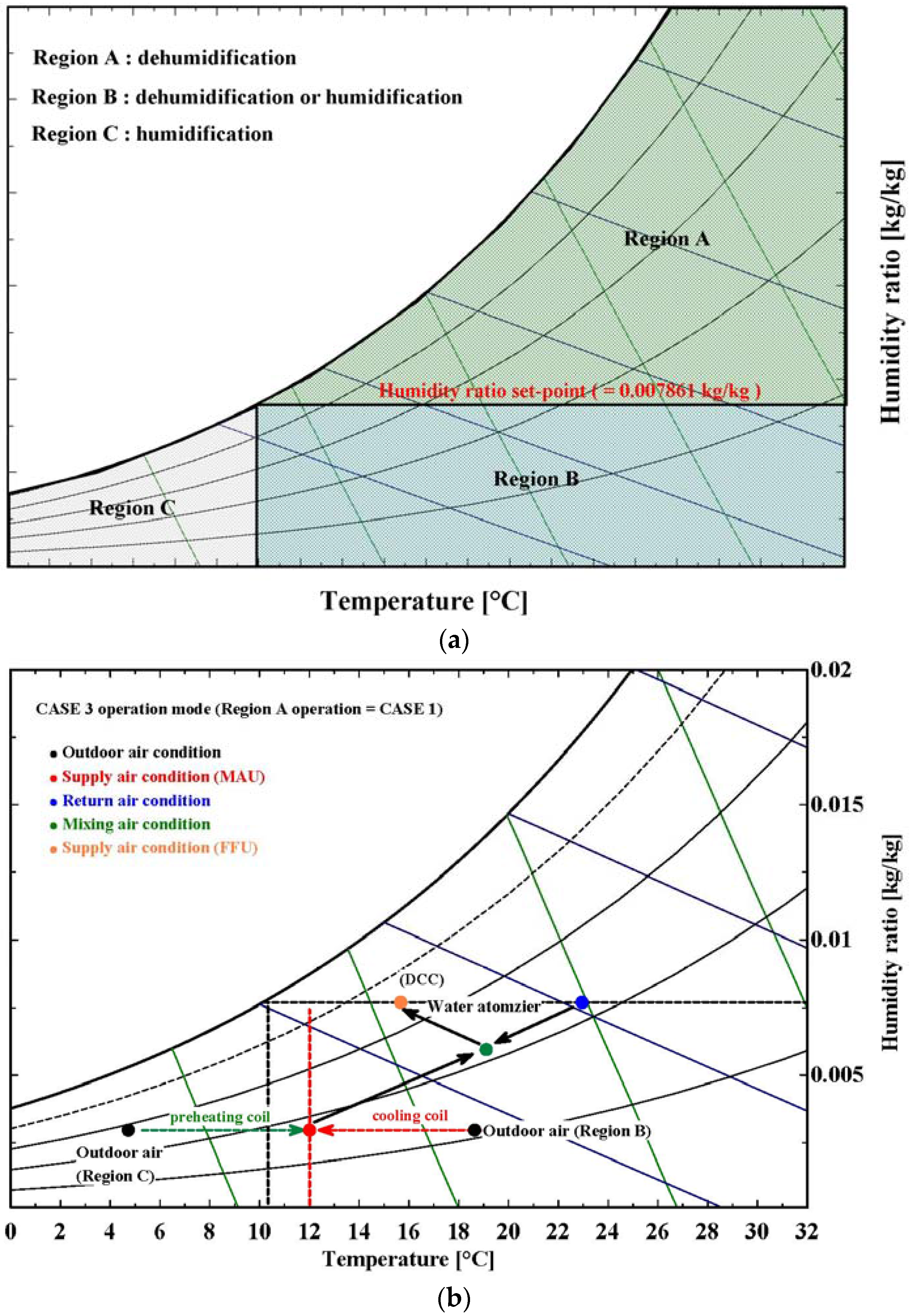
If the outdoor air conditions are included in Region C, the preheating coil load is equivalent for CASE 1 and CASE 3 because the MAU operation is identical. However, in CASE 2, the outdoor air is heated to a higher temperature than that of CASE 1 due to the characteristics of adiabatic humidification (Figure 7). Therefore, the preheating coil load of CASE 2 is increased by 54% as compared to the other cases. Among all the loads, with the exception of the cooling coil load, the steam generation load is the highest in CASE 1 due to the direct-injection steam humidifier and the preheating coil load is the highest in CASE 2 where adiabatic humidification is employed.
HVAC system loads according to the different cases are shown in Figure 11. CASE 1 and CASE 3 show the largest and smallest load in the MAU, respectively. In regard to the DCC load, due to the evaporative cooling effect of adiabatic humidification, CASE 2 and CASE 3 exhibit a decrease of 19% and 33%, respectively, as compared to CASE 1. In addition, CASE 3 with the pressurized water atomizer in the return duct results in a DCC load less than that of CASE 2, which employs a pressurized water atomizer in the MAU. When humidifying by adiabatic humidification method, A greater evaporative cooling effect of CASE 3 compared to CASE 2 due to the airflow to be evaporative cooled more than CASE 2. Therefore, CASE 1 shows the largest total load for the overall HVAC system. CASE 2 and CASE 3, both of which uses a pressurized water atomizer, shows a load reduction of 13% and 32%, respectively, as compared to CASE 1. As a result, water atomizers in cleanroom HVAC systems are expected to reduce energy consumption as to conventional steam humidifiers.
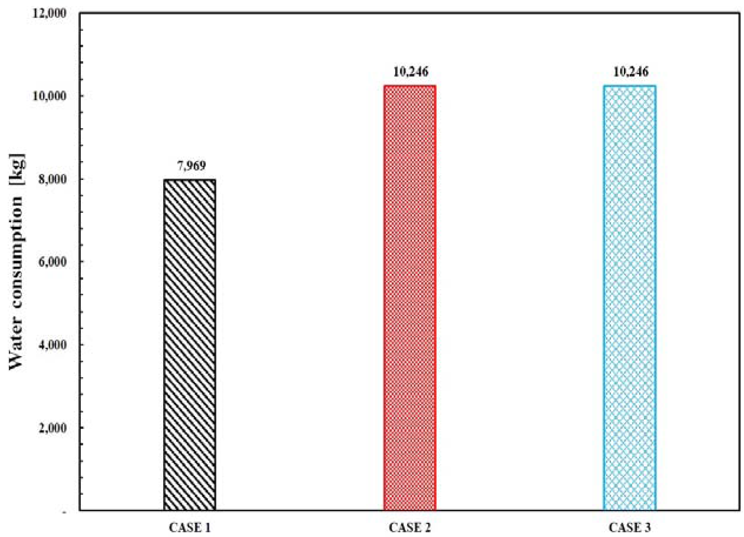
On the other hand, when using direct-injection steam humidifiers and pressured water atomizers for humidifying the air, the amount of required water according to the humidification methods is estimated from different humidification efficiency. Therefore, as shown in Figure 12, due to the lower humidification efficiency of the pressurized water atomizer as compared to that of direct-injection steam humidifiers, the amount of water required for CASE 2 and CASE 3 using the water atomizer is increased by 29% as compared to CASE 1 using the steam humidifier.

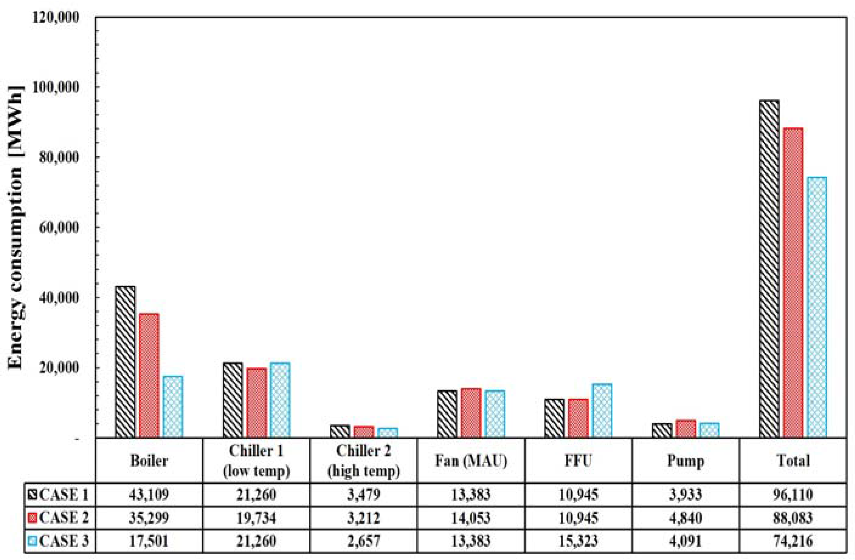
5.3. Comparison of Annual Operating Energy Consumption

Figure 13 shows the energy consumption for the overall HVAC system to maintain the indoor environment of the cleanroom for each case. The components of the entire HVAC system are as follows: a boiler, low temperature chiller, high temperature chiller, fan, FFU, and pump. Additionally, for comparing the energy consumption of HVAC systems, the primary energy conversion factors of electricity and gas were adopted as 2.75 and 1.1 respectively [37].
A boiler is used to process the load of the preheating coil and the direct-injection steam humidifier. To humidify the process air, a large amount of heating energy is required to generate the steam required for the steam humidifier. As a result, the energy consumption of the boiler is the greatest in Case 1. CASE 2 and CASE 3 exhibits a 13% and 56% reduction in of boiler energy consumption compared to CASE 1, respectively, because there is no need for heat energy in the humidification process. Additionally, the preheating coil load required for humidification depends on the location of the pressurized water atomizer (i.e., whether placed in the MAU or in the return duct). The system in CASE 2 consumes about twice the boiler energy as in CASE 3 due to it having the greatest preheating coil load of the three cases.
The chiller energy is consumed by the low-temperature chiller, which supplied low-temperature chilled water to the cooling coil of the MAU, and the high-temperature chiller, which supplied the DCC with relatively high-temperature chilled water. Depending on operating mode of the MAU for each case, the energy consumed by the low-temperature chiller in both CASE 1 and CASE 3 is equivalent. However, in CASE 2, only the pressurized water atomizer operates when the outdoor air condition is included in Region B. Therefore, the low-temperature chiller energy consumption of CASE 2 shows a 7% savings in energy consumption as compared to other cases. The operating energy of the high temperature chiller is the lowest in CASE 3, which employs a pressurized water atomizer in the return duct, due to the evaporative cooling effect of the adiabatic humidification. The DCC load is reduced during the humidification process when the pressurized water atomizer is located in front of the DCC. On the other hand, in CASE 2, when the outdoor air condition is located in Region B, only the pressurized water atomizer operates in the MAU. The supply air temperature in the MAU changes depending on the amount of humidification from evaporative cooling. Accordingly, the air temperature passing through the MAU is higher than the set-point temperature (i.e., 12 °C). Therefore, the DCC load is increased when operating in Region B. However, when the outdoor air condition is in Region C, the air is supplied to the return duct shaft at the dew-point temperature (i.e., 10.4 °C), which is lower than the MAU set-point temperature. The high-temperature chiller load in CASE 2 is reduced, as compared to CASE 1. CASE 2 and CASE 3 exhibit an 8% and 24% reduction in the energy consumption of the high-temperature chiller, respectively, as compared to CASE 1.
The pressurized water atomizer an adiabatic humidification requires the installation of an eliminator. For CASE 2 and CASE 3, the eliminator is assumed to be installed in the MAU and in the return duct, respectively, to prevent carry over. As a result, the energy consumption rate of the fan in the MAU exhibits a 5% increase for CASE 2 as compared to the other cases, whereas the energy consumption of the FFU in CASE 3 exhibits a 40% increase over the other cases due to the large amount of air flow supplied to the cleanroom.
In terms of pump energy, CASE 2 and CASE 3 using the pressurized water atomizer exhibits a 23% and 4% increase in energy consumption with respect to CASE 1, respectively. To inject the fine water droplets from a pressurized water atomizer, a high-pressure pump is required, resulting in an increase in energy consumption relative to the pumps used in direct-injection steam humidifiers. In addition, the droplet size in CASE 2 differs from that in CASE 3 depending on the location of the pressurized water atomizer resulting in different pressure drops at the nozzle. CASE 2, which has a pressurized water atomizer installed in the MAU, has a short evaporation distance than CASE 3 resulting in that spraying finer droplets. On the other hand, in CASE 3, the evaporation distance is longer than that for CASE 2. This results in a larger droplet size and a smaller pressure drop relative to CASE 2. As a result, CASE 3 consumes 15% less energy for pumping as compared to CASE 2.
In regard to the total energy consumption, CASE 3 shows the least amount among the three cases. The energy consumption of CASE 2 and CASE 3 using the pressurized water atomizer exhibits a reduction of 8% and 23%, respectively, relative to CASE 1. In addition, with respect to CASE 2, the greater energy savings in CASE 3 is a result of installation position of the pressurized water atomizer.

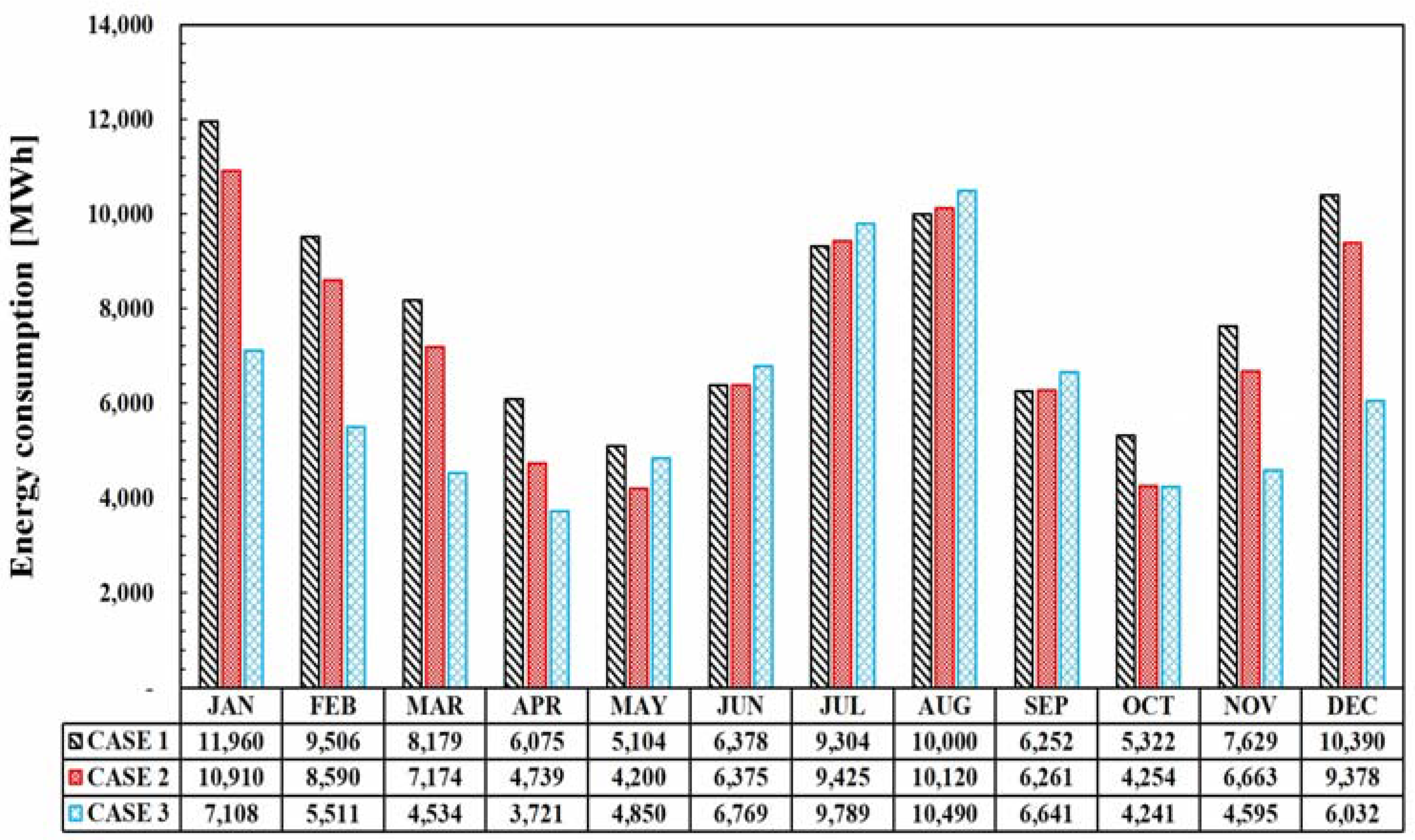
5.4. Comparison of Monthly Operating Energy Consumption

Figure 14 shows the monthly energy consumption of the overall HVAC system for each case. The energy consumption of CASE 1, as a reference case, is at the lowest in June, July, and August, when humidification of the outdoor air is not required, and in September when the humidity of the outdoor air is relatively high. In CASE 2 and CASE 3, an eliminator is necessary to employ a pressurized water atomizer in an HVAC system. In addition, since the amount of airflow supplied from the FFU to the cleanroom is larger than that supplied to the return duct from the MAU, the pressure drop across the FFU is larger than that across the fan in MAU. Therefore, the energy consumption rate of the MAU fan and the FFU increases in CASE 2 and CASE 3, respectively compared to CASE 1. Furthermore, in June, July, August, and September, the total energy consumption rate of the HVAC system is at its highest in CASE 3, whose pressurized water atomizer is installed in the return duct. On the other hand, during winter and the intermediate seasons that require humidification, CASE 2 and CASE 3 exhibit a lower amount of total energy consumption relative to CASE 1. Thus, by replace the steam humidifier with a water atomizer, energy savings can be expected when humidification is required. However, when humidification is not required, HVAC systems with a pressurized water atomizer consumes more energy than systems employing conventional steam humidifiers.

6. Conclusions

In this paper, the applicability of an adiabatic humidification method using a pressurized water atomizer was evaluated. The operating energy consumption and processes of HVAC systems for semiconductor cleanrooms were compared and analyzed as case studies. Three HVAC system cases were studied: CASE 1 included a MAU with a direct-injection steam humidifier, DCC, and FFU. CASE 2 included a MAU with a pressurized water atomizer, DCC, and FFU. CASE 3 included a MAU, DCC, FFU, and a pressurized water atomizer installed in the return duct. When a pressurized water atomizer is employed in an HVAC system, it is necessary to install an eliminator. Because of the increase in energy consumption for the fan, HVAC systems with a pressurized water atomizer consume more energy than those employing direct-injection steam humidifiers when not operating in humidification mode. Also, pressured water atomizer exhibit greater water usage than direct-injection steam humidifiers. However, pressurized water atomizers have an energy-saving potential as compared to conventional direct-injection steam humidifiers because the adiabatic humidification has an evaporative cooling effect and no heat source is required to generate the steam used in conventional steam humidification systems. As a result, CASE 2 and CASE 3 consumed 8% and 23% less total energy relative to CASE 1, respectively. Therefore, pressurized water atomizers for humidification consume lower energy than conventional steam humidifiers in cleanroom HVAC systems. Additionally, a pressurized water atomizer installed in the return duct exhibits greater energy conservation potential than when installed in the MAU.

Acknowledgments

This work was supported by a National Research Foundation (NRF) of Korea (No. 2015R1A2A1A05001726), the Korea Agency for Infrastructure Technology Advancement (KAIA) (grant 17CTAP-C116268-02), and the Korea Institute of Energy Technology Evaluation and Planning (KETEP) (No. 20164010200860).

Author Contributions

Min-Suk Jo, Jang-Hoon Shin, Won-Jun Kim and Jae-Weon Jeong performed the simulation and data analysis, and wrote this paper based on the obtained results.

Conflicts of Interest

The authors declare no conflict of interest.

Glossary

Nomenclature
c p specific heat (kJ/kg·°C)
D diffusion coefficient (m2/s)
d p water droplet diameter (μm)
h enthalpy (kJ/kg)
M water molecular weight (kg/mol)
M ˙ mass flow rate (kg/s)
P pressure drop (kPa)
Q ˙ Load of the component (kW)
R gas constant (J/°K·mol)
T temperature (°K)
t time (s)
V ˙ volume flow rate (m3/s)
W ˙ electrical power consumption (kW)
Abbreviations
CAPFTcooling capacity function of the temperature curve
COPcoefficient of performance
DBdry bulb
EIRFTenergy input to the cooling output ratio function of the temperature curve
EIRFPLRenergy input to the cooling output ratio function of the part load ratio curve
FFUfan filter unit
HVACheating ventilating and air conditioning
IWECinternational weather for energy calculations
MAUmake-up air unit
PCWprocess cooling water
PLRpart load ratio
RHrelative humidity
SHFsensible heat factor
UPWultra-pure water
WBTWet bulb temperature
Greek Symbols
Δ difference
ε efficiency
ρ density (kg/m3)
Subscripts
boiling . w boiling point of water
BFPboiler feed water pump
C C cooling coil
C R cleanroom
c w s cooling water supply
ddroplet
D C C dry cooling coil
E A exhaust air
F F U fan filter unit
H C heating coil
H u m humidification
I indoor environment
i n l e t . w inlet water
M A U make-up air unit
O A outdoor air
P C W process cooling water
P H C preheating coil
r e f reference
s t e a m w a t e r water supplied to steam boiler
W A water atomizer
W A P water atomizer pump

References

  1. Bharath, Y.V.; Reddy, P.L. Design, installation and commissioning of clean room and HVAC facility for stem cell technologies and regenerative medicine. IOSR J. Mech. Civ. Eng. 2013, 8, 1–12. [Google Scholar] [CrossRef]
  2. Cleanrooms and Associated Controlled Environments—Part 1: Classification of Air Cleanliness by Particle Concentration; ISO 14644-1:2015; International Organization for Standardization (ISO): Geneva, Switzerland, 2015.
  3. Rumsey Engineers, Inc. Available online: http://www.rumsey.com/ (accessed on 20 April 2017).
  4. Schrecengost, R.; Naughton, P. Cleanroom energy optimization methods. In Proceedings of the Fourteenth Symposium on Improving Building Systems in Hot and Humid Climates, Richardson, TX, USA, 2004; pp. 17–20. [Google Scholar]
  5. Hu, S.C.; Wu, J.S.; Chan, D.Y.L.; Hsu, R.T.C.; Lee, J.C.C. Power consumption benchmark for a semiconductor cleanroom facility system. Energy Build. 2008, 40, 1765–1770. [Google Scholar] [CrossRef]
  6. Hu, S.C.; Chuah, Y.K. Power consumption of semiconductor fabs in Taiwan. Energy 2003, 28, 895–907. [Google Scholar] [CrossRef]
  7. SEMI. Available online: http://www.semi.org/ (accessed on 20 April 2017).
  8. Brown, W.K. Makeup air systems energy-saving opportunities. ASHRAE Trans. 1990, 96, 609–615. [Google Scholar]
  9. Hu, S.C.; Tsao, J.M. A comparative study on energy consumption for HVAC systems of high-tech FABs. Appl. Therm. Eng. 2007, 27, 2758–2766. [Google Scholar] [CrossRef]
  10. Tsao, J.M.; Hu, S.C.; Chan, D.Y.L.; Hsu, R.T.C.; Lee, J.C.C. Saving energy in the make-up air unit (MAU) for semiconductor clean rooms in subtropical areas. Energy Build. 2008, 40, 1387–1397. [Google Scholar] [CrossRef]
  11. Suzuki, H.; Hanaoka, H.; Ohkubo, Y.; Yamazaki, Y.; Shirai, Y.; Ohmi, T. Energy saving in semiconductor fabs by out-air handling unit performance improvement. Proceeding of the 9th International Symposium on Semiconductor Manufacturing, Tokyo, Japan, 26–28 September 2000; pp. 293–296. [Google Scholar]
  12. Lin, T.; Hu, S.C.; Chang, A.; Lin, C.Y. An innovative ventilation system for cleanrooms with high cooling loads. ASHRAE Trans. 2010, 116 Pt 1, 293–297. [Google Scholar]
  13. Hunt, E.; Benson, D.E.; Hopkins, L.G. Fan efficiency vs unit efficiency for cleanroom application. ASHRAE Trans. 1990, 96, 616–619. [Google Scholar]
  14. Hu, S.C.; Chuah, Y.K.; Huang, S.C. Performance comparison of axial fan and fan-filter unit (FFU) type clean rooms by CFD. ASHRAE Trans. 2002, 108, 1014. [Google Scholar]
  15. Mumma, S.A.; Ke, Y.P.; Sevigny, S.P. Ultrasonic humidification: System integration, energy, and indoor air quality engineering issues. ASHRAE Trans. 1997, 103, 894–905. [Google Scholar]
  16. Li, S.; Willits, D.H. Comparing low-pressure and high-pressure fogging systems in naturally ventilated greenhouses. Biosyst. Eng. 2008, 101, 69–77. [Google Scholar] [CrossRef]
  17. Abdel-Ghany, A.M.; Kozai, T. Cooling efficiency of fogging systems for greenhouses. Biosyst. Eng. 2006, 94, 97–109. [Google Scholar] [CrossRef]
  18. Haeussermann, A.; Hartung, E.; Jungbluth, T.; Vranken, E.; Aerts, J.M.; Berckmans, D. Cooling effects and evaporation characteristics of fogging systems in an experimental piggery. Biosyst. Eng. 2007, 97, 395–405. [Google Scholar] [CrossRef]
  19. Rajasekaran, S.; Prakasam, R.; Handapani, D.; David, V. Prediction of humidification power in textile-spinning mills using functional and neural networks. J. Energy Eng. 2003, 129, 2–15. [Google Scholar] [CrossRef]
  20. Tsao, J.M.; Hu, S.C.; Xu, T.; Chan, D.Y.L. Capturing energy-saving opportunities in make-up air systems for cleanrooms of high-technology fabrication plant in subtropical climate. Energy Build. 2010, 42, 2005–2013. [Google Scholar] [CrossRef]
  21. Chen, J.; Hu, S. Humidification of large-scale cleanrooms by adiabatic humidification method in subtropical areas: An industrial case study. ASHRAE Trans. 2009, 115, 299–306. [Google Scholar]
  22. Performance Rating of Commercial and Industrial Humidifiers; ANSI/AHRI Standard 640-2005; Air-Conditioning, Heating and Refrigeration Institute: Arlington, VA, USA, 2005.
  23. HVAC Fundamental; ASHRAE Handbook; American Society of Heating, Refrigerating and Air-Conditioning Engineers, Inc.: Atlanta, GA, USA, 2015.
  24. Mee Industries Inc. Available online: http://www.meefog.com/ (accessed on 15 May 2017).
  25. Schneider, R.K. Designing clean room HVAC systems. ASHRAE J. 2001, 43, 39–46. [Google Scholar]
  26. International Weather for Energy Calculations; ASHRAE Version 2; American Society of Heating, Refrigerating and Air-Conditioning Engineers, Inc.: Atlanta, GA, USA, 2012.
  27. Chaker, M.; Meher-Homji, C.B.; Mee, T., III. Inlet fogging of gas turbine engines—Part B: Fog droplet sizing analysis, nozzle types, measurement and testing. In Proceedings of the ASME Turbo Expo, Amsterdam, The Netherlands, 3–6 June 2002; pp. 429–441. [Google Scholar]
  28. Suryan, A.; Yoon, Y.K.; Kim, D.S.; Kim, H.D. Experimental investigations on impaction pin nozzles for inlet fogging system. J. Mech. Sci. Technol. 2011, 25, 839–845. [Google Scholar] [CrossRef]
  29. Hinds, W.C. Aerosol Technology: Properties, Behavior, and Measurement of Airborne Particles; John Wiley & Sons: New York, NY, USA, 2012. [Google Scholar]
  30. Ergonomics of the Thermal Environment-Analytical Determination and Interpretation of Thermal Comfort Using Calculation of the PMV and PPD Indices and Local Thermal Comfort Criteria; ISO 7730:2005; International Organization for Standardization (ISO): Geneva, Switzerland, 2005.
  31. Energy Plus. Building Technologies Program; U.S. Department of Energy: Washington, DC, USA, 2013.
  32. Spirax Sarco, Inc. Available online: http://www.spiraxsarco.com/ (accessed on 15 June 2017).
  33. Navien, Technical Data Sheet for NCB 550 27K. Available online: http://us.navien.com/__DATA/Tech/2015/7/1/Navien-NCB-Spec-Sheet.pdf/ (accessed on 6 June 2017).
  34. Munters, Inc. Available online: https://www.munters.com/ (accessed on 10 May 2017).
  35. Klein, S.A.; Beckman, W.A.; Mitchell, J.W.; Duffie, J.A. TRNSYS 17—A Transient System Simulation Program; User Manual; Solar Energy Laboratory, University of Wisconsin-Madison: Madison, WI, USA, 2009. [Google Scholar]
  36. Klein, S.A. F-Chart Software, Engineering Equation Solver, EES Manual; Chapter 1: Getting Started; Solar Energy Laboratory, University of Wisconsin-Madison: Madison, WI, USA, 2013. [Google Scholar]
  37. Park, D.J.; Yu, K.H.; Yoon, Y.S.; Kim, K.H.; Kim, S.S. Analysis of a building energy efficiency certification system in Korea. Sustainability 2015, 7, 16086–16107. [Google Scholar] [CrossRef]
Figure 1. Average energy consumption allocation of semiconductor cleanrooms [6].
Energies 10 01774 g001
Figure 2. Isothermal and adiabatic humidification processes.
Energies 10 01774 g002
Figure 3. CASE 1: MAU with a direct-injection steam humidifier, DCC, and FFU.
Energies 10 01774 g003
Figure 4. CASE 2: MAU with a pressurized water atomizer, DCC, and FFU.
Energies 10 01774 g004
Figure 5. CASE 3: MAU with DCC and FFU with the water atomizer installed in the return duct.
Energies 10 01774 g005
Figure 6. Operating modes for CASE 1. (a) Operating mode of CASE 1; (b) Operating process of the HVAC system in CASE 1.
Energies 10 01774 g006
Figure 7. Operating modes for CASE 2. (a) Operating mode of CASE 2; (b) Operating process of the HVAC system in CASE 2.
Energies 10 01774 g007
Figure 8. Operating modes for CASE 3. (a) Operating mode of CASE 3; (b) Operating process of the HVAC system in CASE 3.
Energies 10 01774 g008
Figure 9. The cooling load of the cleanroom.
Energies 10 01774 g009
Figure 10. MAU load in each case.
Energies 10 01774 g010
Figure 11. Total HVAC system load in each case.
Energies 10 01774 g011
Figure 12. Water consumption rate for each case.
Energies 10 01774 g012
Figure 13. Annual operating energy consumption of each component.
Energies 10 01774 g013
Figure 14. Monthly operating energy consumption of the HVAC system for each case.
Energies 10 01774 g014
Table 1. Humidification methods and systems [23].
Isothermal HumidificationAdiabatic Humidification
Steam heat exchangerAtomization
Hot-water heat exchangerUltrasonic atomizer
Direct-injection steamCentrifugal atomizer
Electrode steamPressurized-water atomizer
Electric resistance steamCompressed air atomizer
GAS-fired steam
Electric infrared steamEvaporationWetted media
Table 2. Properties of the semiconductor cleanroom.
DescriptionValue
Cleanroom area11,182 m2
Ceiling high of cleanroom3.5 m
Indoor air condition23 °C DB (dry bulb),
RH = 45% (relative humidity)
Occupancy500
Product200 mm DRAM
Process tool power7367 kW
Make-up air flow rate1,000,000 m3/h
Recirculation airflow rate6,543,000 m3/h
Exhaust airflow rate9,239,440 m3/h
Table 3. Supply air conditions of the MAU according to the proposed cases.
CASERegionSupply Air Condition
TemperatureHumidity RatioRelative Humidity
CASE 1A12 °C7.861 g/kg (set-point humidity ratio)90%
B
C
CASE 2A12 °C7.861 g/kg90%
B--
C10.4 °C100%
CASE 3A12 °C7.861 g/kg90%
BOutdoor air-
COutdoor air-
Table 4. Factors affecting the load of the semiconductor cleanroom.
FactorDescriptionReference
Q ˙ F F U Load from FFU-
Q ˙ L i g h t i n g Load from lighting which was in kW[30]
Q ˙ O c c u p a n t Load from occupant which was in kW
Q ˙ e n v e l o p e d Enveloped load-
Q ˙ e q u i p m e n t Electric input to process tool[9]
Q ˙ P C W Cooling effect of PCW, with a chilled water flow rate of 0.312 m3/s and temperature difference of 3.2 °C
Q ˙ E A Total cooling effect of the exhaust air (e.g., general, acid, alkaline, or solvent exhaust air), which is estimated to be 495 kW
Table 5. Scheme of the direct-injection steam humidifier and pressurized water atomizer.
DescriptionDirect-Injection Steam HumidifierPressurized Water Atomizer
Inlet water temperature20 °C20 °C
Outlet water or steam temperature (coefficient of performance)120 °C20 °C
Efficiency of pump80%80%
Efficiency of Humidification90% [32]75% [24]
Head of the water from the water tank25 m [9]25 m [9]
Table 6. The specification for the chiller scheme.
DescriptionHigh Temperature ChillerLow Temperature Chiller
TypeAir cooled chillerAir cooled chiller
COP (Coefficient of performance)4.03.5
Temperature of the chilled water supply14 °C6 °C
Temperature of the chilled water return17 °C12 °C
Efficiency of the chilled water pump80%80%
Head of the chilled water pump30 m [9]25 m [9]
Table 7. The specification for the boiler scheme.
DescriptionParameter
TypeCondensing boiler
Efficiency90% [33]
Temperature of the hot water supply55 °C
Temperature of the hot water return50 °C
Efficiency of the hot water pump80%
Head of the hot water pump20 m [9]
Table 8. The specification for the fan and FFU scheme [9].
ComponentPressure Drop
Pre-filter150 Pa
Medium filter200 Pa
Final filter (High efficiency particulate air (HEPA) filter)330 Pa
Coil250 Pa
Eliminator80 Pa [34]
Return duct and DCC80 Pa

