Review: Characterization and Modeling of the Mechanical Properties of Lithium-Ion Batteries


1
Electric Vehicle Safety Lab (EVSL), George Mason University, Fairfax, VA 22030, USA
2
Massachusetts Institute of Technology, Cambridge, MA 02139, USA
*
Author to whom correspondence should be addressed.
Energies 2017, 10(11), 1730; https://doi.org/10.3390/en10111730
Submission received: 30 September 2017
/
Revised: 20 October 2017
/
Accepted: 24 October 2017
/
Published: 30 October 2017
(This article belongs to the Section D: Energy Storage and Application)
Abstract
:Li-ion batteries have become a dominant power source in consumer electronics and vehicular applications. The mobile use of batteries subjects them to various mechanical loads. The mechanisms that follow a mechanical deformation and lead to damage and failure in Li-ion batteries have only been studied in recent years. This paper is a comprehensive review of advancements in experimental and computational techniques for characterization of Li-ion batteries under mechanical abuse loading scenarios. A number of recent studies have used experimental methods to characterize deformation and failure of batteries and their components under various tensile and compressive loading conditions. Several authors have used the test data to propose material laws and develop finite element (FE) models. Then the models have been validated against tests at different levels from comparison of shapes to predicting failure and onset of short circuit. In the current review main aspects of each study have been discussed and their approach in mechanical testing, material characterization, FE modeling, and validation is analyzed. The main focus of this review is on mechanical properties at the level of a single battery.
1. Introduction
Li-ion batteries (LIB) are extensively used in a variety of applications, from portable devices to electric vehicles as well as naval or aerial applications because of their high-energy density, durability, and eco-friendliness. Yet, there are some potential risks associated with using LIBs, especially in the cases of electric vehicles (in land, sea, or air) where they are subject to various loading scenarios (from vibration to crash pulses and impact loading). A number of fire and explosion incidents caused by LIB failure have been reported in recent years [1,2,3,4] which have increased concerns regarding the safe operation of these batteries. It is often difficult to identify the exact cause of failure, after a thermal runaway has occurred, because the battery is damaged and burned. However, the common causes include a manufacturing defect, overcharge or over discharge, and mechanical abuse (e.g., [1,2,3,5]). Quality controls have significantly reduced the instances of failure due to manufacturing defects, and battery management systems often protect against overcharge and over discharge. These topics have been extensively studied in the battery community [6,7,8]. Mechanical abuse on the other hand has only been the subject of research and analysis in recent years (e.g., [9,10,11]). It is understood that mechanical deformations can lead to a failure in the battery and cause fire or explosion in extreme cases (e.g., [2,4]). Failure in these cases can be due to external or internal short circuit. The external short circuit happens when the exterior protection of battery tabs fail and positive and negative terminals come into contact. On the other hand, interior of batteries consists of positive and negative electrodes, i.e., anode and cathode, separated from each other by a porous polymeric layer, called a separator. An indentation to a battery during manufacturing or usage in the field can cause deformation in its components, which in turn can lead to a failure in the separator. Negative and positive electrodes come into contact after separator rupture which leads to internal short circuit in the cell. Short circuit may trigger electrochemical reactions and result in thermal runaway in the LIB cell which can itself turn into a catastrophic event. To prevent such internal short circuits, it is important to understand deformation response of the cell (macro scale) and its components (micro scale). This can be achieved by performing physical tests, characterizing material response, developing computational models, and using analytical methods. These techniques will be specifically useful in the design or optimization of cells and protective structures around them. They will also provide a tool for assessing and mitigating the potential hazards.
This paper reviews the recent developments in mechanical characterization and finite element (FE) modeling of Li-ion cells under mechanical abuse conditions. Abada et al. reviewed experimental and modeling approaches in characterizing the thermal runaway event with a focus on thermal and electrochemical aspects [12]. Grazioli et al. reviewed the multi-physics modeling and simulation of Li-ion batteries at different scales [13]. Franco reviewed the efforts in multi-scale modeling of Li-ion batteries, but again with more focus on electrochemistry [14]. To the best of authors’ knowledge, there are currently no comprehensive reviews of the mechanical abuse testing, material characterization, and numerical modeling studies of Li-ion batteries available in the literature.
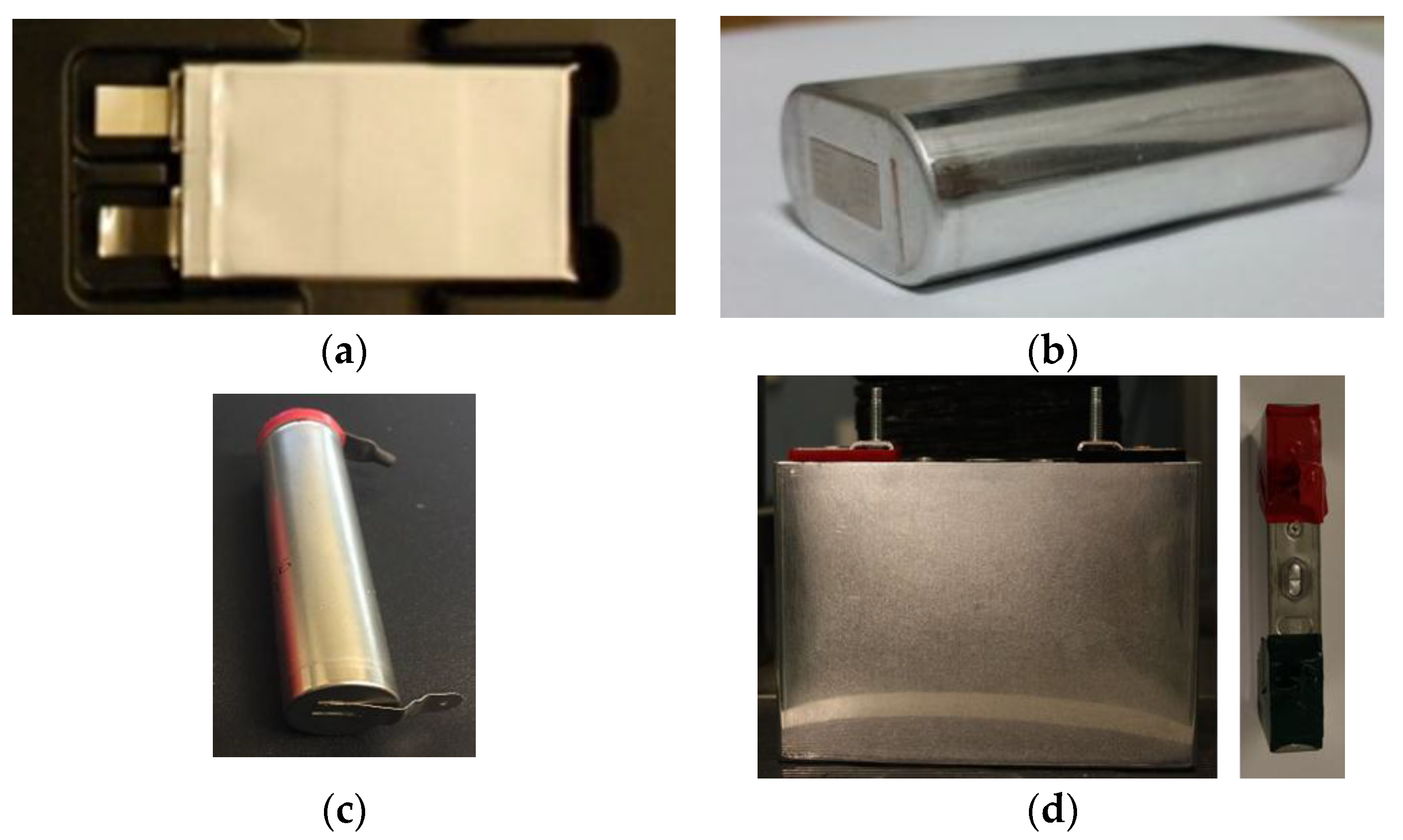
The mechanical properties of LIBs can be studied at various length scales. The smallest scale to study is the level of active material particles in the coatings of anodes and cathodes. Several studies have concentrated on the change of volume, deformation and crack formation in the active particles during the intercalation process in charging and discharging, evolution of degradation phenomena under externally induced mechanical loads and internally induced stress-diffusion coupling, damage evolution, and solid-electrolyte interphase (SEI) formation [15,16,17,18,19,20,21,22,23,24,25,26,27]. These are the main causes of degradation in electrochemical properties of the cells as they go through a large number of cycles. The second step is the component level, which means looking at properties of anodes, cathodes, current collectors, or separators at a single layer but in macro scale [28,29,30,31,32]. The next stage in battery studies is investigating the properties at the single battery level (referred to as cell level in this manuscript). This can be done by considering cells as a homogenous material and ignoring their interior layered structure, or by more detailed analysis of evaluating the interactions of the layers that create a deformation at the cell level [9,33,34,35,36,37,38]. The last step will be considering the problem in hand at the system level, which includes stacks of cells, modules of batteries, and finally battery packs inside a vehicle [39,40,41,42,43,44]. This review is focused on mechanical characterization and modeling efforts at the cell level. Four types of LIBs are commonly used in industrial applications: pouch, elliptical, cylindrical, and prismatic cells, see Figure 1.
In this paper, we summarize the advances in mechanical testing and modeling of the first three form factors separately in each section. The authors could not identify any publications on mechanical properties of prismatic cells. A schematic of the approaches used in investigating the mechanical response of Li-ion batteries is shown in Figure 2. The first step in any analysis is often performing experiments. Mechanical tests are conducted on cell components, full cells, modules, and/or battery packs under various loading conditions. These tests include but are not limited to compression between flat plates, indentation (using hemispherical, cylindrical, conical punches, rigid rod), uniaxial or biaxial tension, and three-point bending. Researchers have used commercial or in-house made battery cells and components and have conducted tests on dry samples to reduce the hazards, or on functional wet cells with electrolyte, to better resemble the field environment. Tests at quasi-static and dynamic speeds have been used to determine the effects of loading rate on the mechanical response. Mechanical characterizations have often been done independent from electrochemical state of the cells and components. It should be noted that the time scale of the mechanical abuse events are often much smaller than thermal or electrochemical loadings. A mechanical accident such as a car crash usually happens in a fraction of a second, while charge and discharge cycles or subsequent thermal events occur in time scale of hours or minutes respectively. Therefore, such cases can be effectively studied independently, and most authors have used this approach.
Going beyond mechanical testing, attempts are made in extracting constitutive material behavior of battery cells or components. Considering the fact that active coating and separators are porous, many researchers have used foam material models to explain their behavior or the cell response. Some researchers have ignored the porosity and proposed incompressible plasticity models for cells. Due to the porous and layered nature of the cell, response is often significantly different under tension and compression. Some components of cells such as separators exhibit strong anisotropy (e.g., [28,47,48,49]). Moreover, due to the layered nature of cells, a structural anisotropy is evident in mechanical response. These features have been considered in a number of studies.
Furthermore, FE models have been developed to investigate the response of the cell under various loading scenarios. Two approaches are generally used: a homogenized cell model and a detailed layered model. The discretization of homogenized models often include using solid elements for a smeared modeling of all layers of the electrode-separator assembly and using shell models for the casing of the battery. In layered modeling, often a combination of solid and shell elements is used, while there have been reports on using only shell layers for all components. Some models have only focused on the deformation and load-displacement response of the cells, while others have also focused on prediction of failure and onset of short circuit. For prediction of short circuit, strain based and stress based failure criteria with different levels of complexity have been proposed.
Finally, the FE models require validation. For this purpose, the first step is to compare the deformation patterns as predicted by FE models versus the experiments. If good agreement is obtained, the load-displacement curves will be compared. More advanced models may predict the onset of the electric short circuit. An ultimate capability for a model is to be able to successfully predict the location and orientation of cracks as measured and observed in the experiments. The models presented in the current literature vary in the level of validation.
The authors have critically studied the major relevant publications in the field of mechanical characterization of Li-ion batteries and categorized them based on their dedication to each of the areas presented in Figure 2. A summary of each study is provided in the following sections categorized by the type of cell form factor, i.e., pouch, cylindrical, and elliptical cells. Additionally, representative papers and their major contributions are summarized in Table A1 of Appendix A.
2. Pouch Cells
Pouch cells have been exceedingly popular in electric vehicle battery packs, such as those found in the Chevy Volt and Nissan Leaf. In this section, the publications reporting on the experimental and computational studies of pouch cells are reviewed. Studies have been organized in chronological order, and publications by the same authors or research groups presented together.
In 2012, Sahraei et al. conducted an extensive experimental study to characterize the mechanical properties of commercially available LiCoO2/graphite small pouch cells in the quasi-static regime [9]. The mechanical tests included through-thickness compression, in-plane unconfined compression, in-plane confined compression, hemispherical punch indentation, and three-point bending, see Figure 3.
Load, displacement, and voltage were recorded over time and the onset of short circuit was determined from the drop in voltage, which coincided with a drop in force. The measured load-displacement curves from through-thickness compression tests were used to characterize a homogenized constitutive model for pouch cells. Experiments showed that cells had very low Poisson’s ratio and therefore using a foam model was suitable for simulation of deformation behavior. Consequently, a crushable foam material (MAT_63 from the LS Dyna library, Livermore Software Technology Corporation, Livermore, CA, USA) was used to simulate the response of pouch cells. In the case of the in-plane unconfined compression tests, significant differences were observed between bare and pouched cells which was explained by a two-layered composite beam model. Short wavelength buckles developed in the cell during in-plane confined compression tests. A theoretical solution for buckling load matched the force level in the experiments. Delamination, rising of the individual layers, and circumferential buckling was observed in hemispherical indentation tests. A stress-strain relationship of the form ( = 566 MPa) was assumed for the cell and a closed-form solution was presented for punch indentation test which was in good agreement with experiments. The bare cell deformation under three-point bending loading resembled that of a clamped beam whilst the pouched cell deformed as a regular simply supported beam. FE models were developed for all mentioned loading cases and were capable of accurately predicting the level of forces and deformation modes. The model also predicted onset of short circuit during a punch loading with very good accuracy. Analytical verifications in conjunction with experimental results identified various parameters characterizing the deformation. The pouch enclosure had a substantial effect on the overall strength of the cell in some loading scenarios, including unconfined in plane loading and 3-point bending indicating the significance of designing suitable shell casings. However, the pouch did not affect the cell response in through-thickness compressions between flat plates or using a hemispherical punch. The results demonstrated that the pouch cell can be considered as a multi-layered anisotropic structure.
Sahraei et al. extended their experimental program to three types of pouch cells (small, medium, and large) with different chemistries (LiCoO2, LiMnNiCoO2, and Nanophosphate) under several loading conditions [36]. Through-thickness compression tests and flat cylindrical punch tests were performed on medium and large cells, respectively, to characterize the constitutive models. In order to complete the calibration and validation process and investigate the conditions leading to the development of an internal short circuit, the three types of cells were indented with one conical punch and three hemispherical punches (12.7 mm, 28.575 mm, and 44.45 mm in diameter). The onset of short circuit was identified with a local peak in force, a drop in voltage, and a rise in temperature, see Figure 4a. It was observed that short circuit occurred earliest for the conical punch and was delayed with increase in punch diameter. The peak load at short circuit increased linearly with punch diameter. In the case of conical punch indentation into a large pouch cell, a soft short circuit preceded a complete short circuit. An FE model for each cell (using crushable foam material) under small punch indentation was developed. A homogenous isotropic constitutive model of the form was calibrated based on the experimental results and used as an input for the FE model. These simulations were used to calibrate the maximum tensile strain criterion (using Mat-Add-Erosion) and the tensile cut-off value. Developed FE models for each cell successfully predicted the load-displacement curves, the peak force and the punch displacement at the onset of short circuit, indicating that the isotropic homogeneous model was capable of representing a range of battery chemistries, sizes, and loading conditions. These models were validated using medium and large punch tests. The coefficient of friction between the punch and the cell was identified as one of the parameters that can affect the accuracy of results.
Hemispherical punch tests on LiFePO4 pouch cells with different state of charge (SOC) levels, ranging from 0% to 100%, are reported by Meier et al. [50]. The results suggest that cells exhibited similar load-displacement curves prior to the onset of short circuit. The peak load varied within 25% in the tested SOC range, however, no trend was found between the peak load and SOC.
In a separate study by Sahraei and her colleagues in 2015, formation of cracks in battery cells at onset of short circuit was investigated [51]. For this purpose, a small pouch cell with SOC < 10% was indented with a hemispherical punch up to the point of short circuit. A linear crack perpendicular to the transverse direction of the separator was detected using computed tomography (CT) scanning. A homogenized anisotropic FE model was developed for the cell, where properties in each direction were separately characterized in tension and compression. The compressive properties were calibrated from through-thickness flat compression tests. Tensile tests were performed on electrodes, separators, and current collectors as well as a multi-layer specimen consisting of all layers. Results of tensile tests showed consecutive failure of layers. The first component that failed in tension was cathode (aluminum current collector), then the anode (copper current collector) failed, and the separator was the last layer to fail. An equivalent curve was developed using the volume average of the layers. The curves were significantly different in transverse and machine direction of the separator. The anisotropic average equivalent tensile properties were used as input to the homogenized modified Honeycomb material model. The main focus of this study was to properly detect the orientation and location of the crack at the point of failure and short circuit in the cell. Using the anisotropic model with distinct tensile and compressive features was a key factor in achieving this goal. CT scan results were used to verify orientation of the crack and proper values for tensile strain to failure.
Kisters et al. (2017) conducted dynamic impact tests on two types of pouch cells (one with Nickel Manganese Cobalt (NMC) and one with Nickel Cobalt Oxide chemistry) using a hemispherical punch at various crosshead velocities up to 5000 mm/s and SOC = 0 [38]. Load, punch displacement, and cell voltage were measured during the tests. For both pouch cell types, the peak force and the critical depth decreased by a factor of two as the crosshead velocity increased from 0.01 to 5000 mm/s. In a separate study, Kermani and Sahraei [52] used these tests to characterize the material and failure properties of pouch cells at high loading speeds. A power type constitutive model () was assumed to describe the compressive stress-strain response of the cells at each test velocity and the principal of virtual work was applied to determine the model coefficients directly from load-displacement measurements. Further analysis indicated that a constitutive model of the form , as in Johnson-Cook material model, with = 2 was able to successfully describe the strain-rate hardening behavior of the cell. An FE model was developed for the cell and modified crushable foam material from LS Dyna library was adopted in order to account for its strain rate dependent behavior. Failure strains were calibrated by comparing load-displacement curves from experiments and simulations. A negative linear relationship was found between the failure strain and the normalized strain rate. The results suggested that the decrease in peak force and failure strain was a result of reduced ductility at higher strain rates.
Breitfuss et al. developed in 2013 a detailed layered model of LiMn2O4/graphite pouch cells [53]. Tensile tests were conducted on each cell component, in dry and wet conditions, and in axial and transverse directions. Dry and wet specimens exhibited similar behavior. Material models of each layer were calibrated from tensile tests. Isotropic Mat-Piecewise-Linear-Plasticity model (from LS Dyna library) was used for active particles, current collectors, and cover sheets, while an elastic orthotropic model was used for the separator. Mat-Add-Erosion was added to account for the failure in the separator. Models for each layer was validated against the tensile test of that layer and then a model of the entire cell was developed, all using LS Dyna. Tied contact with failure was chosen to describe the interaction forces between layers. Cohesive interactions were modeled using solid layers and Mat-Cohesive-Mixed-Mode material model. Multiple quasi-static tests, namely three point bending (with and without pouch), in-plane unconfined compression, and impactor (with a cylindrical rod), were conducted on cells in charged versus discharged states. The fully charged cells exhibited higher force levels, however this effect was not significant and was ignored in the numerical model. There was a good agreement in the force levels obtained from cell test results and simulations. However, the simulations were not fully successful in predicting the load-displacement curves and the deformation patterns. In this study, no attempt was made to characterize compressive behavior of components or full cells experimentally. This should explain the difference in simulation predictions versus test results.
In 2014, Lai et al. characterized the mechanical response of dry in-house made Li-ion phosphate (LiFePO4/graphite) battery cells [54]. They conducted quasi-static out-of-plane and constrained in-plane compression tests on cell Representative Volume Element (RVE) specimens, as done by Sahraei et al. [9], see Figure 3a,e. The RVE consisted of 10 cathodes, 10 anodes, 21 separators, and two aluminum cover sheets (without electrolyte). For in-plane constrained compression tests three stages were identified in nominal stress-strain curves: an initial linear region is evident with effective compressive elastic modulus of 188 MPa which is followed by a sudden change in the slope at the strain of about 0.02. After this point, the slope remains constant until strain of about 0.2 after which the slope increases gradually up to strains of about 0.34. The three stages correspond to the development of elastic buckling of individual components with a wavelength approximately in the order of the cell thickness, formation of kinks and shear bands, and final densification of cell components, respectively. It should be noted that in the later stages of deformation, the so-called layer micro buckling of components was observed. The buckling modes and the critical buckling stress agreed well with those from the elastic buckling analysis for a beam supported by unattached elastic foundations. An idealized kinematic model was presented to explain the physical mechanisms of the kink and shear band formation in such loadings. In case of the out-of-plane compression, cell RVE specimens showed a lower stress response as compared to in-plane compression test suggesting that the RVE specimens are anisotropic, which confirmed findings of Sahraei et al. [9] This softer response was mainly due to the gaps between the components and the porous nature of the separator and electrodes. The stress increased sharply with densification of the cell components until nominal strain of about 0.4 after which the cell RVE exhibited a linear elastic response [54].
Ali et al. developed a detailed layered model of cell RVE specimens of Li-ion battery cells under quasi-static constrained in-plane compression loading in ABAQUS/explicit (Dassault Systèmes, Vélizy-Villacoublay, France) [55]. The buckling analysis previously reported in [54] justified the cell RVE length selection in FE simulations. Tensile tests [10], in-plane constrained compressive tests, and the rule of mixture were used to characterized the mechanical properties of each component. The Gurson’s yield function was adopted to model the porous electrodes and the separator as isotropic homogenized porous sheets. A parametric study was conducted to determine the contact coefficient of friction and the initial void volume fraction. The FE model successfully predicted the stress-strain response of the cell RVE and the buckling patterns observed in the experiments (patterns similar to Figure 3e). Ten half waves were obtained from simulations which was comparable to seven half waves observed in tests [54]. Further simulations showed that reducing the initial clearance resulted in formation of more kinks with shorter depth and more shear bands. Equi-biaxial in-plane constrained compression was simulated and the interaction of shear bands was visualized. Sung et al. reported on in-plane compression tests on cell RVE specimens with various out-of-plane pre-strains [56]. The results indicated that stress levels as well as the number of half waves increased with pre-strain. The elastic buckling analysis of a beam showed similar trends.
In a separate study, Lai et al. reported on in-plane compression tests on in-house made module RVE specimens [10]. The module RVE consisted of two seven-unit cells separated by an aluminum heat dissipater and with two foam layers on the sides. Same as the behavior of cells and RVEs, the stress-strain of modules resembled the response of cellular material, meaning it exhibited an initial linear region followed by a plateau and a final densification region, but with local peaks in stress. System imperfections and loading conditions determined the details of stress-strain curve. Additional tests were conducted on module RVE sets with different heights and with adhesives. The results showed that the module RVE height did not affect the general shape and magnitude of the stress for strains below 30%; however the stress increased at a higher rate in double-heighted specimens after strains of 30%. Module RVE specimens with adhesives experienced higher stress as compared to ones with no adhesives under in-plane compressive loading. This was expected since the bending stiffness of aluminum heat dissipater increases if bonded to the cover sheet. The analytical results showed that the heat dissipater contributed to more than 90% of the buckling stress.
Out-of-plane compression tests were conducted on foam layer [10] and cell components [54] and the corresponding stress-strain curves were used along with the rule of mixture to determine the out-of-plane response of the module RVE. Similar to the trend seen in cells (Figure 4b), the curves from the in-plane compression are 5–8 MPa higher than, and parallel to, those from the out-of-plane tests. These results indicate that foam material can be used to model the module RVE as well. Lai et al. also conducted tensile tests on cell components (anode, cathode, separator, cover sheet, and aluminum heat dissipater sheet) in the quasi-static region until failure [10]. The results showed that the active materials did not have any load carrying capacity. These tests are especially useful for developing a macro homogenized material model for batteries based on the responses of individual components. The composite rule of mixture was used to estimate the tensile properties of the cell RVE and the module RVE.
In 2015, Ali et al. [39] developed 2D and 3D symmetric half models in ABAQUS implicit solver in order to simulate a module RVE under circular punch indentation. Two isotropic macro homogenized material models, hyperfoam and crushable foam, were adopted for the module RVE in 2D and 3D models, respectively. Material models were calibrated based on the nominal stress-strain curve reported in [10] for in-plane compression tests on the double-height module RVE. For validation purposes, a quasi-static constrained in-plane circular punch (80 mm in diameter) indentation test was conducted on a small-scale module RVE specimen [10]. Simulation results were in overall good agreement with experiments in terms of load-displacement response and deformation patterns. However, the macro model was not able to capture the initial yielding and the buckling behavior of the module RVE.
In 2017, Amodeo et al. developed a semi-homogenized FE model of module RVE specimen under in-plane constrained compression loading in both quasi-static and dynamic regions [57]. The model consisted of two homogenized cells, a heat dissipater, and two foams on each side based on the quasi-static experiments reported in [10,54]. The crushable foam material from LS Dyna library was adopted for the module RVE based on out-of-plane compression tests. Strain rate dependency was not considered for any of the materials. The module RVE showed a higher stress response in dynamic tests as compared to quasi-static experiments. Furthermore, the nominal stress at which the initial buckling of the heat dissipater occurred in the dynamic case was about twice as high as that in the quasi-static one. Quasi-static and dynamic simulations were successful in predicting the stress-strain response and the deformation patterns as observed from experiments. The authors associated the observed changes in the model to inertia effect, as no strain rate dependency was considered in material models for various parts. This finding is in contrast with all FE simulations of Sahraei and co-workers which show minimal kinetic energy for punch loading simulations of batteries [58].
In 2014, Ren et al. conducted pinch-only and pinch-torsion tests on a dry prototype cell (stack of one anode, one cathode, and one separator) as well as commercial cellphone Li-ion pouch cells using two rods with hemispherical ends at Oak Ridge National Laboratory [59]. This was an extension of the group’s previous work in showing repeatable short circuit creation using pinch tests [60]. The onset of short circuit was determined by the change in cell resistance and by a drop in voltage in prototype and pouch cells, respectively. Test results showed that short circuit occurred at lower loads in pinch-torsion tests as compared to pinch-only ones which can be explained by the material flow in the lateral direction as a result of torsion-induced shear force. Using optical microscopy, it was observed that the damaged zones in the separators were smaller in pinch-torsion tests. Further pinch-torsion tests on commercially available pouch cells at different SOCs showed that a hard short circuit is more probable to occur at higher SOCs. However, peak loads were not a function of SOC. This observation is consistent with the experimental results of Meier et al. [50]. A Thermal Runaway Risk (TRR) scoring system was proposed based on two measured parameters, cell voltage and surface temperature.
In continuation of the above research, Xia et al. developed a three-layer unit FE model in ABAQUS (3DS SIMULIA) to simulate pinch-only and pinch-torsion tests [61]. The unit consisted of a layer of high density polyethylene (HDPE) separator sandwiched between an aluminum and copper layer (with no active material coating). Aluminum and copper layers were modeled using elastic-plastic solids with isotropic hardening laws, following [62], and the HDPE separator was modeled using a hyperelastic Neo-Hookean material model, based on [63]. The simulations were carried out in two steps. First, pinch-only tests were modeled using axisymmetric elements. In this case, separator failed due to high tensile strain caused by the contact. A local tension zone was predicted in the separator near the indenter but outside the contact area which agreed qualitatively with the experimental observations. In the second step, displacement and stress fields from the first step were imported into a 3D model and torsion was applied with a maximum twist angle, , of 12°. Results showed that adding the torsion component did not change the size of the tension zone in the separator. However, the maximum first principal strain increased significantly when torsion was added (increased by 77% at = 12°) which explains the earlier failure in the separator in this case. Further studies showed that the maximum principal strain increased linearly with up to 3°, after which the slope of principal strain- curve decreased until reaching a plateau at a critical angle of 5°. At 5° the indenter was able to freely spin relative to the cell and the value of principal strain in this region depended on the friction coefficient between the indenter and the cell. The simulation results showed that the maximum principal strain increased monotonically with the friction coefficient. An analytical stick-slip model was presented to explain the observed trend between maximum principal strain and .
Kumar et al. simulated the spherical indentation of Li-ion pouch cells using different punch sizes [64]. Two FE models were developed in LS Dyna, a layered model and a homogenized one. In the layered model, the top four layers had details of electrode-separator assembly, and the rest was modeled as a single homogenized material. Separator and electrodes (combined coating with current collectors) were modeled using Mat-Piecewise-Linear-Plasticity and crushable foam material, respectively. Failure criterion was defined as the maximum strain in the separator. Voigt average technique was used to calculate the elastic modulus of the homogenized part. In the homogenized model, the cell was modeled using crushable foam material using material parameters following [36] and the failure criterion was defined by tensile cut-off stress value. The simulation results were compared with experiments reported in [36]. It was found that the failure criterion of the layered model was not dependent on the punch size, however in the case of the homogenized model tensile cut-off value should be calibrated from each experiment separately. This conclusion is in contrast with findings of Sahraei et al. [36] that used crushable foam model with a single tensile cut-off value and a single failure criterion of maximum principal strain for each of the three pouch cells they modeled and were able to predict closely failure of pouch cells indented with hemispherical rigid punches of 12–44.5 mm.
Wang et al. reported on spherical indentation tests on commercially available large NMC/graphite pouch cells (SOC = 25% and 75%) [40]. A steel ball (25.4 mm in diameter) was used to indent single cells as well as stack of three cells in a progressive manner at indentation depths between 0.635 mm (0.025″) to 6.35 mm (0.25″) in increments of 0.635 mm. Voltage was measured during the tests. Thermal runaway was observed at indentation depths larger than 6.22 mm (0.245″). The response of the three-cell stack was nonlinear for indentation depths of less than 1.9 mm (0.075″), but became linear afterwards. The cells were cut open after the tests and optical images of the separator were acquired. The thinning area in the separator became larger and more anisotropic (oval shaped transparent area) as the indentation depth increased. In order to calibrate material models for the cell components, flat plate compression tests were conducted on stacks of positive electrode, negative electrode, and pouch material, and tensile tests were conducted on separator layers in different directions. In order to simulate the spherical indentation loading, an FE model was developed in LS Dyna in which the top four layers represented the details of electrode-separator assembly, and the rest was modeled as a single homogenized layer. The crushable foam material was used to model the electrodes (with tensile cut-off value of 1 GPa) as well as the homogenized part. The separator was modeled using Mat-Piecewise-Linear-Plasticity. No failure was considered for the components. Same procedure as outlined in [64] was used to calculate the homogenized mechanical properties. The stack of three cells was modeled by adding two additional homogenized layers under the modeled described above. Load-displacement results from cell and three-cell stack simulations were in good agreement with experiments. The areas of deformation in the separator (at two indentation depths) was determined by visualizing the contours of through-thickness compressive strain and compared to the transparent areas observed from images. The measured and the predicted area were in good agreement. An FE model with anisotropic separator was also developed using Mat-3-paramater-Barlat and a failure criterion of a maximum through-thickness strain was defined for the separator. The anisotropic model was more successful in predicting the short circuit, i.e., drop of force. It should be noted that materials used for the separator in this research (MAT-Piecewise-Plasticity and Mat-3-parameter-Barlat) are models for incompressible materials such as metal sheets, while as reported in the literature (e.g., [26]), the separator is a porous compressible layer.
Zhang et al. developed a one-way coupled mechanical-electrical-thermal model for a LiCoO2/graphite pouch cell under quasi-static spherical punch indentation [65]. The mechanical part of their model is described here. Two detailed layered FE quarter models were developed in LS Dyna using thick shell elements: a single representative sandwich model or RS (consisting of one layer of anode, one layer of cathode, and two layers of separator with a scaled equivalent thickness) and a full cell model (including 20 representative sandwich units). An exponential type constitutive model was suggested for active material layers and separator and calibrated based on the experimental data reported in [9,33]. Current collectors were modeled using Mat-Plastic-Kinematic following the tests reported in [33]. Crushable foam material model was adopted for separators and active materials. The failure criterion of a maximum compressive strain was added to the separator using Mat-Add-Erosion and calibrated by comparing the load-displacement curves form the RS model with those reported in [9]. Assuming a compression only failure criterion for separators is in contradiction with the findings of Zhang et al. that showed separators do not fail under compressive loads alone [47]. Load-displacement results from the single RS and the full cell models were in good agreement with those from experiments. The single RS model was capable of predicting the onset of short-circuit, however no distinct drop in force was predicted in the full cell model. The mechanical deformation was subsequently input into a coupled electrical-thermal solver and reasonable predictions for the current density, temperature distribution, and electrical short circuit were obtained.
In a separate study, same group extended their single RS model to account for simultaneous interactions between mechanical and electrical-thermal responses [66]. In their new model, cell components were modeled using solid elements. Modified honeycomb material was used to define distinct compressive and tensile mechanical properties for the separator and the active materials. The separator was assumed to be isotropic in compression and orthotropic in tension referring to [28]. In contrast to the previous study of the authors, here a maximum tensile failure criterion was considered for the separator. The models of indentation tests with three different punch sizes were capable of reproducing the mechanical response and the onset of short circuit as reported in [36] as well as the crack development. It should be noted that the authors change the tensile failure strain for each punch size to match location of failure in the simulations with the tests. The coupled model could successfully predict the electric and thermal responses using a distance-based electrical contact criterion.
Luo et al. conducted a series of interrupted and uninterrupted hemispherical punch tests on pouch cells (LiNixCo1−x−yMnyO2/graphite) in the quasi-static region [67]. The cell voltage was measured during the tests. Preliminary results indicated that the cell response was independent of the SOC level (in the range of 10 to 50%). Therefore, tests were performed on cells with SOC < 10%. In the case of uninterrupted tests, three stages were identified on the load-displacement curve. In Stage I, the cell stiffness increases until there is an inflection point in the curve (at about load level of 5.5 kN) after which the stiffness drops a bit and enters a plateau region (Stage II). The load increases in this stage until it reaches a peak. At this point the load and the cell stiffness drop dramatically due to the failure in the cell (Stage III). In order to study the cell failure mechanism, indentation was interrupted at fixed load levels (4.0, 5.5, 6.0, 7.0 and 8.0 kN) at which the cell was unloaded and Scanning Electron Microscopy (SEM) was used to examine the cell components, separator and anode. Prior to the inflection point on the load-displacement curve, no sign of fracture was detected in neither the anode nor the separator. At the force level of 6 kN, which corresponds to the inflection point, SEM images showed a transparent portion on the separator which matched an area with silver speckles on the anode. This point was the initiation of separator thinning and anode decoating. This finding corroborated reports of Zhang et al. on separator failure modes and inflection point under biaxial loading [30]. This local damage to anode and separator before the onset of short circuit can explain the decrease in cell stiffness in the Stage II observed in uninterrupted tests. At higher load levels, these areas became larger and a small part of the active material delaminated from the anode and adhered to the separator. Eventually, simultaneous fracture in current collectors and separators lead to the drop in force at about 8.8 kN. SEM image analysis demonstrated that more than one third of the separators exhibited local thinning and fracture at this load level and that the extent of deformation was more pronounced in the layers closer to the punch.
Marcicki et al. developed a coupled structural-electrochemical-thermal model in LS Dyna to simulate the response of pouch cells under spherical and cylindrical impact loading [68]. Tensile tests in different directions as well as compression tests were conducted on the separator and electrodes to determine their material properties and FE models were developed to validate the models. In the mechanical model the separator, the active materials, and the current collectors were each represented by a single layer of thick shell elements. The separator and active materials were modeled using Mat-Simplified-Rubber/Foam and the metal sheets were modeled using modified piecewise linear plasticity. The compressive failure strain and the ultimate stress of the coating materials were calibrated to match the peak load and its corresponding displacement from experiments. The mechanical simulations have not been validated against any experiments. However, the simulation results indicated that the failure occurred earlier and at a lower load level in the case of the spherical indenter as compared to the cylindrical one.
3. Cylindrical Cells
Cylindrical cells are the most common cells used in various application from consumer electronics to some electric vehicles such as the Tesla Model S. Due to their wound jellyroll inside a hard shell casing, the behavior of cylindrical cells under mechanical loading is distinct from that of pouch cells. In this section studies focused on mechanical properties of cylindrical cells are presented.
Extensive testing program was conducted by Sahraei et al. on 18650 Li-ion cells with LiCoO2 chemistry (SOC = 10%) in order to characterize their response [35,69]. The experiments included indentation by a rigid rod, indentation by a hemispherical punch, three-point bending, and axial and lateral flat compression, see Figure 5. The onset of short circuit was detected by tracking the cell voltage and temperature.
The test results were used to calibrate material properties and validate the FE models. In the case of the three-point bending, the cell initially exhibited a linear elastic response. Three distinct local peaks were identified on the load-displacement curve. First and second peaks coincided with the formation of folds in and the fracture of shell casing, respectively. The third peak corresponds to the onset of short circuit in the cell. The crack in the shell casing propagated almost to two thirds of the cell diameter which may have accelerated the cell failure. For the flat compression tests, the end caps were removed, making it possible to visualize the deformation of interior layers. The cell cross section had two distinct regions, a flat section adjacent to flat platens which were connected by two semi-circular regions. Halfway through the experiments, the layers delaminated inside the semi-circular regions. Tensile tests were conducted on the steel shell casing in order to characterize its plastic properties. Closed form solutions showed that the contribution of the shell casing to the overall strength of the cell was less than one percent in cases of flat compression and rod indentation. However, in case of the three-point bending it contributed to about half of the cell strength. In order to develop a computational model, the jellyroll was assumed to be homogeneous and isotropic with different properties in tension and compression. Crushable foam material from LS Dyna library was used. The compressive constitutive model of the form ( = 550 MPa) was assigned to the jellyroll. This model was based on the compressive tests on the pouch cells. The results from the rigid rod and hemispherical punch indentation tests were used to calibrate and validate the value of tensile cut-off strength. The location of short circuit was determined as the first element that reached and maintained a tensile principal stress of 10 MPa. The FE model was capable of predicting the load-displacement data, cell deformation, crack formation in the shell casing, and onset of short circuit.
Zhang and Wierzbicki conducted a comprehensive research to characterize the plastic and fracture behavior of the shell casings of 18,650 cylindrical cells [70]. For this purpose, the parameters of the Swift-Voce hardening law as well as the Modified Mohr-Coulomb fracture model were calibrated based on the tensile tests and punch indentation tests on low carbon steel shell casing samples. The hardening and fracture models were validated through lateral and axial compression, three-point bending, and internal pressure experiments. An FE model of the full cell was developed in ABAQUS to simulate two loading scenarios, namely three-point bending and lateral indentation with cylindrical punch. The jellyroll was modeled following [35,41]. The results indicated that the shell casing had a significant contribution to the strength of the cell.
The cracks developed in an 18,650 cylindrical cell subject to mechanical loads were modeled by Sahraei et al. [51]. For this purpose, tensile properties of electrode-separator components were obtained and used to develop an anisotropic model for an 18,650 cylindrical cell, using LS Dyna-modified honeycomb material. The model was calibrated and validated against indentation tests with rigid rod and with hemispherical punch (SOC < 10%). The location of the cracks in the simulations was consistent with that from CT scanning. Cracks were perpendicular to the transverse direction of the separator. The anisotropic model showed improved predictability as compared to the isotropic one. Using a homogeneous material model for jellyrolls is justified for lateral loading scenarios. However, due to the layered structure of jellyrolls, it is important to distinguish between the mechanical properties of each layer when subject to axial loads. Zhu et al. studied the 18,650 cylindrical cells in axial compression (SOC = 0) using experimental, numerical, and analytical approaches [46]. A detailed axisymmetric 3D FE model was developed in ABAQUS/explicit to investigate the sequence of deformation and failure mechanisms. This model accounted for the layered structure of the cell as well as the anisotropy of cell components (where applicable). Mechanical properties were obtained from previous studies of the same research. The load-displacement response from the simulations was in good agreement with experiments. Four distinct stages of deformation were identified on the load-displacement curves. Shell casing bended at the cap region (Stage I) and then underwent axial compression (Stage II). Buckling occurred in the shell casing followed by a decrease in force (Stage III). Eventually the force increased due to the larger contact area between the top end and the jellyroll and short circuit occurred at a displacement of 4 mm (Stage IV). These results were validated with Micro CT scans as well as analytical solutions. By opening the cell after testing, it was concluded that a large area of crack in the separator and some creases in the separator were the main causes leading to short circuit.
Greve and Fehrenbach studied the mechanical behavior of large cylindrical NCO Li-ion cells (SOC = 0) in the quasi-static regime under three different loading scenarios: compression between flat plates (lateral crush), lateral indentation, and three-point bending [34]. Voltage and temperature were recorded during the tests, and the initiation of short circuit was identified by a drop in voltage and an increase in temperature. CT scans of the cells after three-point bending indicated that the load drop observed at the point of short circuit was due to a macroscopic fracture in the jellyroll. This type of fracture was not observed in the other loading conditions. An FE model was developed in Virtual Performance Solution software using shell elements for the stainless steel shell casing and solid elements for the jellyroll. A modular user material model (previously developed by Volkswagen Group Research) was adopted for the cell casing. Tensile tests on the specimens from the housing exhibited a normal anisotropic behavior which was represented by the classical Hill48 yield criterion. The casing strain hardening was represented by the modified Swift law. The FE model of shell casing was then validated against a three-point tube bending test. A generalized plasticity model was proposed for modeling the interior of the cell. This model was simplified to describe the homogenized isotropic response of the jellyroll and reduced to a J2 plasticity model. The results of the lateral crush tests were used to characterize the material model for jellyroll. The load-displacement curves from simulations of bending and indentation loadings closely followed those from experiments. The stress-based Mohr-Coulomb (MC) criterion can proposed for detection of the fracture behavior under compressive, shear, and normal stress. The authors propose calibration of MC parameters by visualizing the final principal stresses of all load scenarios from FE simulations. They envision that MC criterion will be able to successfully predict the location of the failure and the corresponding punch displacement based on the principal stress histories observed in the FE simulations.
Lamb and Orendorff reported on blunt rod indentation tests in the axial and lateral directions on two types of commercially available 18,650 cylindrical cells, one with proprietary mixed metal oxide chemistry without a solid core and one with LiCoO2 chemistry with a solid core [71]. Voltage and temperature were measured during the tests and the internal structure of the cells was analyzed after testing using CT scanning. Two failure modes were identified in the case of lateral indentation on cells without a solid core: a hard short circuit where the rod penetrated several layers into the cell and a soft one where the failure was localized at the outer layers of the cell and the electrodes deformed into the hollow center. The lateral indentation tests on the cell with a solid core resulted only in hard short circuits which were at lower indentation depths as the electrodes were sandwiched between the rod and the solid core. The peak temperature was higher in the cell with a solid core which may be due to different cell chemistries. By increasing the test temperature to 60 °C, lateral indentations resulted in a soft short at a lower peak force and smaller indentation depth in the cell without a solid core, whist a lower peak force and more energetic failure was observed in the cell with a solid core.
Avdeev and Gilaki studied the mechanical behavior of a dry commercially available 6P NCA/graphite cylindrical Li-ion cell with an aluminum inner tube [72]. Two different approaches were used to characterize a homogenized material model of the jellyroll. In the first approach, flat plate compression tests were conducted on flattened jellyroll samples and the stress-strain curves were directly calculated from load-displacement measurements (assuming constant cross sectional area). In the second approach, lateral crush tests were conducted on cylindrical samples of the jellyroll and the homogenization method using the principle of virtual work, suggested by [73], was extended to larger cells under such loading conditions. A fit of the form was able to describe the experimental load-displacement curve and a constitutive model of the form was derived. In both approaches it was assumed that a rectangular area under plates carried load. The curves obtained from the two homogenization approaches diverged at strains exceeding 10%. It was discussed that the application of virtual work principle was not accurate due to the presence of the inner hole as well as the complex state of stress in the jellyroll. Therefore, a crushable foam material model based on the first approach material model was adopted for jellyroll in LS Dyna. Load-displacement curves from simulations were in good agreement with those from experiments. Drop tests (2.8 m; 11.34 kg and 22.68 kg) were conducted on cells and a 3D FE model of the impact was developed in LS Dyna. The model consisted of jellyroll (modeled with crushable foam material with a tensile cut-off value of 10 MPa [35,73]), shell casing and core tube (modeled with piecewise linear plasticity material), and internal spacers (modeled with Mat-Plastic-Kinematic). All components were modeled using solid elements. The cell was impacted by a rigid plate with velocity of 7.4 m/s and strain rate dependency was ignored in the model. A good agreement was found between the geometry of the cell deformation predicted by the simulations and those observed in the tests. CT scanning of the deformed cells confirmed the simulation results. In the continuation of this research, the same group investigated the effect of electrolyte on the jellyroll response [74]. For this purpose, flat plate compression tests were conducted on flattened jellyroll specimens which were saturated in dimethyl carbonate (DMC). Results indicated that the electrolyte did not have a significant effect on the compressive response of the jellyroll. Additionally, flat plate compression tests were conducted on stacks of coated aluminum layers, coated copper layers, and separator. Results showed that the coated aluminum layers were twice as stiff as coated copper layers. A detailed layered FE model of the cylindrical cell was developed in which each layer of the jellyroll was modeled using a crushable foam material calibrated from the compressive test results and a tensile cut-off value. The shell casing and the core tube were modeled as in [72]. The impact of a rigid plate with a mass of 11.34 kg and a speed of 7.4 m/s was simulated. The results of the homogenized FE model were in good agreement with the layered FE model, in terms of predicting the impact velocity, impact load, and deformed shapes. However, no comparison was presented between the load-displacement or velocity curves of FE models and experiments.
Based on the experiments and material models reported by Greve and Fehrenbach [34] on NCO Li-ion cells, Xu et al. developed an FE model in ABAQUS. The model consisted of shell casing, end caps, jellyroll, and plastic sleeve [11]. The constitutive model of the jellyroll was assumed to be of the form similar to [34]. The model was validated against the load-displacement measurements form the lateral compression, indentation, and bending tests in [34]. A failure criterion was suggested based on three principal stresses and the Unified Strength Theory. All simulation cases in the quasi-static region were used to calibrate the proposed failure model based on the collective numerical results. The calibrated failure criterion was not used to predict any new case of failure for the purpose of validation. In order to extend the model to the dynamic regime, Johnson-Cook model was used to apply the strain rate dependent behavior of the jellyroll as well as the shell casing and end caps. The results of the simulations (velocity = 0.1–30 m/s) indicated that with increasing the impact velocity, failure occurred earlier and the failure location changed. In the case of simulation of the bending loading, the cell deformed differently in the dynamic region with higher force levels. After using the UST criteria on dynamic simulations, an empirical model was suggested for dynamic failure strain that would give same results as the UST model. Parametric studies in the case of the indentation loading showed that crushing angles and positions had a noticeable effect on the failure strain. Simulations showed the effect of battery size was only significant in bending loading indicating that a slender cell was less prone to failure. No validation against experiments was presented for neither the simulation cases nor the suggested failure criteria.
Xu et al. also reported on lateral compression and bending tests on 18,650 cylindrical cells at SOCs in the range of 0% to 70% [75]. Voltage was measured during the tests. In the case of the lateral compression tests, a higher level of force was observed at higher SOCs. The onset of short circuit was associated with a nominal strain that coincided with the drop in voltage. Furthermore, cell components were retrieved from cells at SOC = 0% and 30%. Tensile tests were conducted on the shell casing as well as the separator and lateral compression tests were conducted on the anode, the cathode, and the separator. Results showed that SOC only affected the response (equivalent compressive modulus) and the thickness of the anode. At cell level, in both compression and bending loadings, stiffness increased linearly with SOC whilst nominal failure strain exhibited an inverse linear relationship with the SOC level.
In the continuation of their previous research, Xu et al. conducted bending, indentation, and lateral and axial compression tests on commercially available LixC6/LiCoO2 18,650 cylindrical cells in the quasi-static region [76]. An FE model was developed which incorporated the anisotropy of the jellyroll and the strain-rate dependency of the jellyroll and shell casing. The homogenized anisotropic (transversely isotropic) material parameters of the jellyroll were calibrated based on compression tests and validated against the other experimental results. It was shown that using an anisotropic model was necessary to successfully predict the mechanical response of the cell under bending. Through an analogy with strain-rate effect, a model of the form where was suggested to represent the effect of SOC. The results of the simulations were compared with those from lateral compression and bending tests at various SOCs. Furthermore, drop-weight tests were conducted with initial impact velocities of 2–3.5 m/s to study the effects of dynamic loading. Two stages were identified on the load-displacement curve: Stage I with low dynamic effects corresponding to the elimination of the gaps in the cell and Stage II with high dynamic effects corresponding to the densification of the jellyroll. Therefore, a two-stage dynamic model was proposed. The effect of SOC was also included in the model. Experimental and numerical results suggested that higher levels of force (stress) were obtained at higher SOC and at higher velocities.
Raffler et al. conducted flat plate compression tests in the lateral and axial directions as well as indentation tests with a cylindrical rod on commercially available 18,650 cylindrical cells (SOC = 100%) in the quasi-static region [77]. Cell voltage was measured during the tests and the onset of internal short circuit was identified with a drop in voltage which coincided with a drop in force. In the case of the axial compression tests, short circuit occurred in the positive pole. An FE model of the cylindrical cell was developed in LS Dyna using discrete beam elements. The deformation patterns observed from indentation tests were compared with those from simulations to determine the number of elements in longitudinal and radial directions. Mass and stiffness of the elements were adopted to match the cell mass and radial mechanical resistance. The model consisted of four components: radial and circumferential beam elements, axial beam elements at the two ends (representing the poles), remaining axial beam elements, and shell elements (representing the casing). General spring/damper material and NULL material were assigned to beam elements and shell casing, respectively. Material properties were assumed to be the same in tension and compression. A metamodel based optimization algorithm was used to calibrate the material parameters based on experimental load-displacement curves (using LS-Opt). A compressive strain failure criterion was suggested based on the global deformation of the cell. Three-point bending tests were also performed to verify the modeling approach. No internal short circuit was observed under three point bending. There was a drop in force due to shell casing fracture. Simulations were able to give realistic predictions of cell deformation. Using the discrete beam elements, the simulation time of a single cell decreased by 90% as compared to solid elements.
4. Elliptical Cells
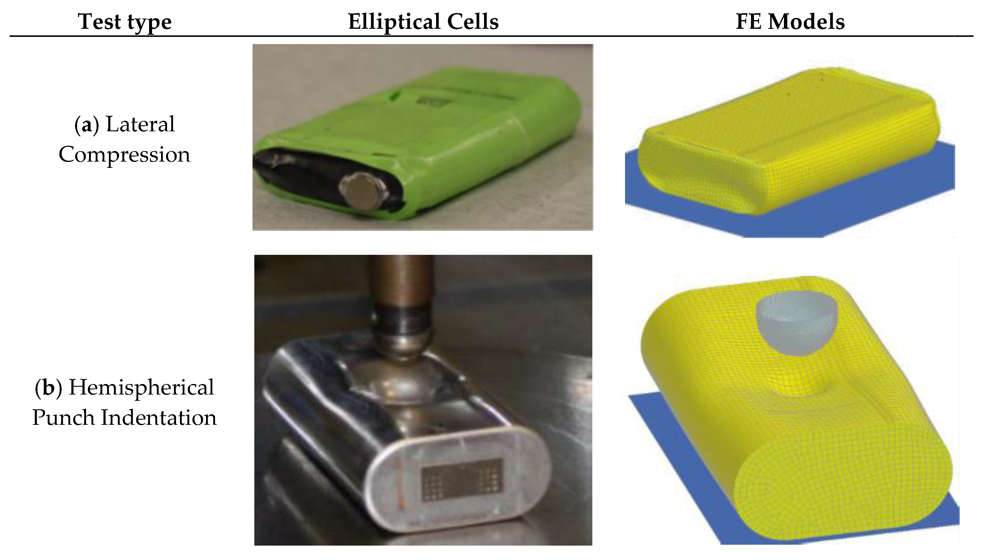
Elliptical cells are a kind of prismatic cell. Similar to cylindrical cells, they contain a wound jelly roll inside a hard shell casing. However, in the flat central section of the cell, the stack of layers resembles the electrode assembly of a pouch cell. These cells have not been studied in terms of mechanical properties until very recently. The relevant publications on elliptical cells are presented in this section. Sahraei et al. conducted extensive experiments on cell components in order to investigate the deformation and failure of elliptical Li-ion cells at the microscale level [45]. For this purpose, elliptical cells (NCM/graphite) and their components were obtained from the manufacturer. Uniaxial tensile and biaxial tests along with FE simulations were used to characterize the plastic properties, compressive stress-strain curves, and calibrate the failure strains of each component. To characterize the anisotropy in the separator, tensile tests were performed in both machine and transverse directions. The material models were used to develop a 2D microstructural FE of the RVE in LS Dyna including one layer of anode, two layers of separator, and one layer of cathode. Crushable foam material model was used for the separator (properties in the transverse direction were considered) and actives materials. Piecewise linear plasticity material model was used for copper and aluminum foils. The failure in the separator was modeled using Mat-Add-Erosion and the fracture of current collectors was modeled by constrained tied nodes failure. Periodic boundary conditions were applied. Various loading scenarios with different ratios of compressive and tensile loads were simulated. Results showed that the type of loading significantly affects the sequence of failure in the components and the tensile failure strain is a function of the ratio of compressive to tensile deformation. Using homogenization technique, a macro model for the cell was calibrated from through-thickness compressive loading. The failure locus plotted from the micro model was used to estimate the failure strain for two scenarios of compression loading between two flat plates and hemispherical punch indentation. Using the homogenized compressive/tensile properties and the estimated failure strains, the FE model showed good agreement with the experimental results in terms of predicting both the load-displacement curve and onset of short circuit. Sahraei et al. reported on extensive quasi-static experiments on elliptical cells in three configurations, namely dry (without electrolyte), wet (with polyethylene carbonate solution), and live (commercial, discharged) [58]. A drop in voltage and/or resistance measured during tests was used to identify the onset of short circuit. In-plane compression tests in the transverse direction were conducted on wet and dry cells. The inspection of the cells revealed that the wet and dry cells exhibited different fraction patterns. The wet cell had fracture lines in only one direction, but the dry cell had fracture lines in two directions which can be explained by different fracture coefficients in dry and wet cells. It was also shown that the type of separator in wet cells affected the peak force. For the case of in-plane compression tests in the axial direction, wet, dry, and live discharged cells showed similar load-displacement curves until short circuit occurred. The point of short circuit coincided with the initiation of buckling in the electrode assembly. The force continued to increase until reaching a peak and then dropped. The values and the displacements of the second peak force were different for different cells. Two buckling folds were observed on the aluminum shell casing. An FE model of an elliptical cell was developed in LS Dyna (Figure 6). The model consisted of three parts, jellyroll, shell casing, and two end caps. Jellyroll was modeled using solid elements and crushable foam material. Shell elements and piecewise linear plasticity material were used for end caps and the shell casing. Results from out-of-plane compression tests on the cell and tension tests on individual components [45] were used to calibrate homogenized compressive and tensile material properties of the jellyroll. The FE model was used to simulate hemispherical indentation loading as well as compression between flat plates. The load-displacement results from the simulations were in good agreement with those from experiments and the onset of failure was predicted in the hemispherical indentation case.
Kisters et al. (2017) conducted dynamic impact tests on dry and live Nickel Oxide elliptical cells using a hemispherical punch at various crosshead velocities up to 5000 mm/s and SOC = 0 [38]. Onset of short circuit was identified by a drop in voltage in case of live cells which coincides with peak force. Two failure modes were observed which were explained by the soft and hard internal short circuit theory for separators [30]. The results suggested that the occurrence of soft short circuit may not be easily detected at higher impact velocities. Wet and dry cells showed similar load-displacement curves, however, wet cells exhibited lower levels of force due to the effects of electrolyte. For both elliptical cell, the peak force increased with an increase in the crosshead velocity. This trend was more pronounced in dry cells. This observation was in contrast with the trend observed for pouch cells subject to similar loading scenarios. The comparison between the level of loads in elliptical and pouch cells indicated that pouch cells exhibited higher critical loads at lower crosshead velocities and lower critical loads at higher velocities. In a follow up study by Kermani and Sahraei, a similar approach to what was described previously in Section 2 for pouch cells was applied to the test data from dynamic tests on elliptical cells [52]. It was shown that a Johnson-Cook type constitutive model with = 2.5 could describe the cell strain rate dependent response. An FE model consisting of jellyroll (with modified crushable foam material) and shell casing and end caps (with Mat-Piecewise-Linear-Plasticity) was used to simulate the dynamic impact tests. The failure in the model was included by using Mat-Add-Erosion and maximum principal strains were calibrated by comparing load-displacement curves from experiments and simulations. It was found that failure strain increased linearly with the normalized strain rate. This observed trend in elliptical cells is in contrast with that found for pouch cells (see Section 2) and suggests that the underlying deformation and failure mechanisms are different in the two cell types. The differences were associated with the competing effects that strain rate hardening and heat generation during plastic deformation have on the strength and ductility of each component.
5. Discussion and Conclusions
In this review we discussed and analyzed various approaches of mechanical testing, material characterization, finite element modeling, and validation procedures used in investigating the mechanical integrity of Li-ion batteries at the cell level. Considering the overall state of the art, the following statements summarize findings and recommendations for each of the above categories:
Mechanical tests: several researchers have conducted mechanical tests on full cells and battery components. Full cell tests are often to generate compressive loads. This has been done in a variety of punch loading settings, using hemispherical or cylindrical punches. Cells have been loaded while located on flat surfaces or pinched on two sides. Deformation has been applied through the thickness or in-plane. At component level, both tensile and compressive tests have been done. The tensile tests are either uniaxial to characterize plasticity, or biaxial to detect onset of failure. Compressive tests are often performed on stacked layers because a single layer with sub millimeter thickness would not produce accurate results.
Material characterization: it has been shown by various researchers that foam type materials are good candidates for modeling the homogenized cell response. An anisotropic model can produce more precise prediction especially in terms of failure location and direction, while simple isotropic foam models still produce accurate results in terms of global response of the cell. Properties are significantly different in tension and compression, and the models that consider this variation produce more predictive responses.
FE Models: finite element analysis provides a cost effective tool which can be used to optimize the design parameters and improve the safety of the cells without the need to conduct more experiments. Depending on application of the model, different levels of detail have to be included. A model that is developed to simulate a cell in a battery pack for vehicle level crash has different requirements than a model to design layers of electrode and separators for improved mechanical integrity. The former requires the largest possible element size to reduce computational time and has to only predict global deformations and failures, while the latter has to include as many details as possible from electrode separator assembly to clarify effects of interactions between layers. The failure has been predicted using strain-based or stress-based models, yet several proposed criteria still lack proper validation.
Validation: the most important step for any FE model is its validation against experiments. Different levels of validation have been presented in the literature, ranging from no validation to prediction of details in the failed region of the cell. The lowest level of validation is a general comparison of shape of deformation and a comparison of load-displacement response. The models that incorporate failure criteria may predict onset of electric short circuit. Only the models that include all complexities of cell multi-layer multi-material structure can provide predictions on exact location and direction of cracks.
Acknowledgments
This work was supported by the Office of Naval Research under contract number N00014-17-1-2869 and the MIT Battery Consortium, with industrial members including Daimler, Jaguar-Land Rover, AVL, and Peugeot-Citroën.
Author Contributions
Both authors contributed to the writing of this paper.
Conflicts of Interest
The authors declare no conflict of interest. The founding sponsors had no role in the design of the study; in the collection, analyses, or interpretation of data; in the writing of the manuscript, and in the decision to publish the results.
Appendix A

Table A1.
Representative papers and their major properties of in mechanical characterization of Li-ion batteries. The notations here are following what presented in Figure 2.
Table A1.
Representative papers and their major properties of in mechanical characterization of Li-ion batteries. The notations here are following what presented in Figure 2.
| Mechanical Tests | Constitutive Models | FEM | Validation | |||||||||||||
|---|---|---|---|---|---|---|---|---|---|---|---|---|---|---|---|---|
| Cell Type (P,C,E) | References | Cell Condition (W,D) | Level (I,C,M,P) | Manufacturer (H,CM) | Loading Speed (QS,D) | Material Type (F,IP) | Properties (T,C) | Anisotropy (I,A) | Strain Rate (Y,N) | Model (H,DL) | Elements (S,SH,B) | Failure | Load-Displacement | Onset of Short Circuit | Location of Cracks | Orientation of Cracks |
| P | [9] | W | C | CM | QS | F | T,C | I | N | H | S | Y | Y | - | - | |
| P | [36] | W | C | CM | QS | F | T,C | I | N | H | S | Y | Y | - | - | |
| P | [51] | W | C | CM | QS | F | T,C | A | N | H | S | Y | Y | Y | Y | |
| P | [38,52] | W | C | CM | Dy | F | T,C | I | Y | H | S | Y | Y | - | - | |
| P | [54,55] | D | C | H | QS | F | T,C | I | N | DL | S/SH | - | Y | - | - | - |
| P | [10,39] | D | M | H | QS | F | T/C | I | N | DL | S/SH | - | Y | - | - | - |
| P | [57] | D | M | H | QS, Dy | F | T/C | I | N | DL | S | - | Y | - | - | - |
| P | [53] | W,D | C | CM | QS | F | T | A | N | DL | SH | Y | Y | - | - | |
| P | [40] | W | C,M | CM | QS | F | C | I | N | H/DL | S | Y | Y | - | - | |
| C | [35,73] | W | C | CM | QS | F | T,C | I | N | H | S | Y | Y | Y | - | |
| C | [51] | W | C | CM | QS | F | T,C | A | N | H | S | Y | Y | Y | Y | |
| C | [34] | W | C | CM | QS | F | C | A | N | H | S | Y | - | - | - | |
| C | [72] | D | C | CM | QS | F | C | I | N | H | S | - | - | - | - | |
| C | [74] | W | C | CM | QS | F | C | I | N | DL | S | - | - | - | - | - |
| C | [11] | - | - | - | - | - | C | I | Y | H | S/SH | Y | - | - | - | |
| C | [77] | W | C | CM | QS | SD | C | A | N | H | B | Y | Y | - | - | |
| E | [45] | D | I | CM | QS | F | T,C | I | N | DL | SH | Y | Y | - | - | |
| E | [58] | W,D | C | CM | QS | F | T,C | I | N | H | S | Y | Y | - | - | |
| E | [38,52] | W,D | C | CM | Dy | F | T,C | I | Y | H | S | Y | Y | - | - | |
References
- Mikolajczak, C.; Kahn, M.; White, K.; Long, R.T. Lithium-Ion Batteries Hazard and Use Assessment; Springer Science & Business Media: Berlin, Germany, 2011. [Google Scholar]
- Chevrolet Volt Battery Incident Overview Report; National Highway Traffic Safety Administration: Washington, DC, USA, 2012.
- Interim Factual Report; National Tansportation Safety Board - Office of Aviation Safety: Washington, DC, USA, 2013.
- Fire-Propulsion Battery-Road Debris; National Highway Traffic Safety Administration: Washington, DC, USA, 2014.
- Feng, X.; Ouyang, M.; Liu, X.; Lu, L.; Xia, Y.; He, X. Thermal runaway mechanism of lithium ion battery for electric vehicles: A review. Energy Storage Mater. 2017. [Google Scholar] [CrossRef]
- Lu, L.; Han, X.; Li, J.; Hua, J.; Ouyang, M. A review on the key issues for lithium-ion battery management in electric vehicles. J. Power Sources 2013, 226, 272–288. [Google Scholar] [CrossRef]
- Hannan, M.A.; Lipu, M.S.H.; Hussain, A.; Mohamed, A. A review of lithium-ion battery state of charge estimation and management system in electric vehicle applications: Challenges and recommendations. Renew. Sustain. Energy Rev. 2017, 78, 834–854. [Google Scholar] [CrossRef]
- Khan, M.; Swierczynski, M.; Kær, S. Towards an Ultimate Battery Thermal Management System: A Review. Batteries 2017, 3, 9. [Google Scholar] [CrossRef]
- Sahraei, E.; Hill, R.; Wierzbicki, T. Calibration and finite element simulation of pouch lithium-ion batteries for mechanical integrity. J. Power Sources 2012, 201, 307–321. [Google Scholar] [CrossRef]
- Lai, W.J.; Ali, M.Y.; Pan, J. Mechanical behavior of representative volume elements of lithium-ion battery modules under various loading conditions. J. Power Sources 2014, 248, 789–808. [Google Scholar] [CrossRef]
- Xu, J.; Liu, B.; Wang, L.; Shang, S. Dynamic mechanical integrity of cylindrical lithium-ion battery cell upon crushing. Eng. Fail. Anal. 2015, 53, 97–110. [Google Scholar] [CrossRef]
- Abada, S.; Marlair, G.; Lecocq, A.; Petit, M.; Sauvant-moynot, V.; Huet, F. Safety focused modeling of lithium-ion batteries: A review. J. Power Sources 2016, 306, 178–192. [Google Scholar] [CrossRef]
- Grazioli, D.; Magri, M.; Salvadori, A. Computational modeling of Li-ion batteries. Comput. Mech. 2016, 58, 889–909. [Google Scholar] [CrossRef]
- Franco, A.A. Multiscale modelling and numerical simulation of rechargeable lithium ion batteries: Concepts, methods and challenges. RSC Adv. 2013, 3, 13027. [Google Scholar] [CrossRef]
- Zhao, K.; Pharr, M.; Vlassak, J.J.; Suo, Z. Fracture of electrodes in lithium-ion batteries caused by fast charging. J. Appl. Phys. 2010, 108, 1–7. [Google Scholar] [CrossRef]
- Zhao, K.; Pharr, M.; Hartle, L.; Vlassak, J.J.; Suo, Z. Fracture and debonding in lithium-ion batteries with electrodes of hollow core-shell nanostructures. J. Power Sources 2012, 218, 6–14. [Google Scholar] [CrossRef]
- Di Leo, C.V.; Rejovitzky, E.; Anand, L. A Cahn-Hilliard-type phase-field theory for species diffusion coupled with large elastic deformations: Application to phase-separating Li-ion electrode materials. J. Mech. Phys. Solids 2014, 70, 1–29. [Google Scholar] [CrossRef]
- Salvadori, A.; Bosco, E.; Grazioli, D. A computational homogenization approach for Li-ion battery cells: Part 1 - Formulation. J. Mech. Phys. Solids 2014, 65, 114–137. [Google Scholar] [CrossRef]
- Salvadori, A.; Grazioli, D.; Geers, M.G.D. Governing equations for a two-scale analysis of Li-ion battery cells. Int. J. Solids Struct. 2015, 59, 90–109. [Google Scholar] [CrossRef]
- Hofmann, T.; Müller, R.; Andrä, H.; Zausch, J. Numerical simulation of phase separation in cathode materials of lithium ion batteries. Int. J. Solids Struct. 2016, 100–101, 456–469. [Google Scholar] [CrossRef]
- Shim, J.; Kostecki, R.; Richardson, T.; Song, X.; Striebel, K.A. Electrochemical analysis for cycle performance and capacity fading of a lithium-ion battery cycled at elevated temperature. J. Power Sources 2002, 112, 222–230. [Google Scholar] [CrossRef]
- Cheng, X.B.; Zhang, R.; Zhao, C.Z.; Wei, F.; Zhang, J.G.; Zhang, Q. A review of solid electrolyte interphases on lithium metal anode. Adv. Sci. 2015, 3, 1–20. [Google Scholar] [CrossRef] [PubMed]
- Safari, M.; Morcrette, M.; Teyssot, A.; Delacourt, C. Life Prediction Methods for Lithium-Ion Batteries Derived from a Fatigue Approach. J. Electrochem. Soc. 2010, 157, A892. [Google Scholar] [CrossRef]
- Behrou, R.; Maute, K. Numerical Modeling of Damage Evolution Phenomenon in Solid-State Lithium-Ion Batteries. J. Electrochem. Soc. 2017, 164, A2573–A2589. [Google Scholar] [CrossRef]
- Behrou, R.; Maute, K. Multiscale modeling of non-local damage evolution in lithium-ion batteries. ECS Trans. 2017, 77, 1163–1177. [Google Scholar] [CrossRef]
- Bucci, G.; Swamy, T.; Chiang, Y.-M.; Carter, W.C. Modeling of internal mechanical failure of all-solid-state batteries during electrochemical cycling, and implications for battery design. J. Mater. Chem. A 2017, 5, 19422–19430. [Google Scholar] [CrossRef]
- Peabody, C.; Arnold, C.B. The role of mechanically induced separator creep in lithium-ion battery capacity fade. J. Power Sources 2011, 196, 8147–8153. [Google Scholar] [CrossRef]
- Sheidaei, A.; Xiao, X.; Huang, X.; Hitt, J. Mechanical behavior of a battery separator in electrolyte solutions. J. Power Sources 2011, 196, 8728–8734. [Google Scholar] [CrossRef]
- Cannarella, J.; Liu, X.; Leng, C.Z.; Sinko, P.D.; Gor, G.Y.; Arnold, C.B. Mechanical Properties of a Battery Separator under Compression and Tension. J. Electrochem. Soc. 2014, 161, F3117–F3122. [Google Scholar] [CrossRef]
- Zhang, X.; Sahraei, E.; Wang, K. Li-ion battery separators, mechanical integrity and failure mechanisms leading to soft and hard internal shorts. Sci. Rep. 2016, 6, 32578. [Google Scholar] [CrossRef] [PubMed]
- Zhang, X. Mechanical Behavior of Shell Casing and Separator of Lithium-ion Battery; Massachusetts Institute of Technology: Cambridge, MA, USA, 2017. [Google Scholar]
- Kalnaus, S.; Wang, Y.; Turner, J.A. Mechanical behavior and failure mechanisms of Li-ion battery separators. J. Power Sources 2017, 348, 255–263. [Google Scholar] [CrossRef]
- Hill, R.L. Development of a Representative Volume Element of Lithium Ion Batteries for Thermo-Mechanical Integrity; Massachusetts Institute of Technology: Cambridge, MA, USA, 2011. [Google Scholar]
- Greve, L.; Fehrenbach, C. Mechanical testing and macro-mechanical finite element simulation of the deformation, fracture, and short circuit initiation of cylindrical Lithium ion battery cells. J. Power Sources 2012, 214, 377–385. [Google Scholar] [CrossRef]
- Sahraei, E.; Campbell, J.; Wierzbicki, T. Modeling and short circuit detection of 18650 Li-ion cells under mechanical abuse conditions. J. Power Sources 2012, 220, 360–372. [Google Scholar] [CrossRef]
- Sahraei, E.; Meier, J.; Wierzbicki, T. Characterizing and modeling mechanical properties and onset of short circuit for three types of lithium-ion pouch cells. J. Power Sources 2014, 247, 503–516. [Google Scholar] [CrossRef]
- Dixon, B. Material characterization of lithium ion batteries for crash safety; Massachusetts Institute of Technology: Cambridge, MA, USA, 2015. [Google Scholar]
- Kisters, T.; Sahraei, E.; Wierzbicki, T. Dynamic impact tests on lithium-ion cells. Int. J. Impact Eng. 2017, 108, 205–216. [Google Scholar] [CrossRef]
- Ali, M.Y.; Lai, W.J.; Pan, J. Computational models for simulation of a lithium-ion battery module specimen under punch indentation. J. Power Sources 2015, 273, 448–459. [Google Scholar] [CrossRef]
- Wang, H.; Kumar, A.; Simunovic, S.; Allu, S.; Kalnaus, S.; Turner, J.A.; Helmers, J.C.; Rules, E.T.; Winchester, C.S.; Gorney, P. Progressive mechanical indentation of large-format Li-ion cells. J. Power Sources 2017, 341, 156–164. [Google Scholar] [CrossRef]
- Xia, Y.; Wierzbicki, T.; Sahraei, E.; Zhang, X. Damage of cells and battery packs due to ground impact. J. Power Sources 2014, 267, 78–97. [Google Scholar] [CrossRef]
- Ellersdorfer, C.; Sevarin, A.; Tomasch, E.; Sinz, W.; Ebner, A.; Deitermann, N.; Forster, M. Evaluation Method of the Crash Safety of Traction Batteries for Electric Driven Mototrcycles. In Proceedings of the 11th International Motorcylce Conference, Cologne, Germany, 3–4 October 2016. [Google Scholar]
- Wisch, M.; Ott, J.; Thomson, R.; Léost, Y.; Abert, M.; Yao, J. Recommendations and Guidelines for Battery Crash Safety and Post-Crash Safe Handling; EverSafe; Vol. D3.1. Available online: http://www.eversafe-project.eu/files/pages/554/deliverables/d3-1-eversafe-guidelinesforbatterysafetyandsafehandling-recommendationscrashcompatibility.pdf (accessed on 30 October 2017).
- Kukreja, J.; Nguyen, T.; Siegmund, T.; Chen, W.; Tsutsui, W.; Balakrishnan, K.; Liao, H.; Parab, N. Crash analysis of a conceptual electric vehicle with a damage tolerant battery pack. Extrem. Mech. Lett. 2016, 9, 371–378. [Google Scholar] [CrossRef]
- Sahraei, E.; Bosco, E.; Dixon, B.; Lai, B. Microscale failure mechanisms leading to internal short circuit in Li-ion batteries under complex loading scenarios. J. Power Sources 2016, 319, 56–65. [Google Scholar] [CrossRef]
- Zhu, J.; Zhang, X.; Sahraei, E.; Wierzbicki, T. Deformation and failure mechanisms of 18650 battery cells under axial compression. J. Power Sources 2016, 336, 332–340. [Google Scholar] [CrossRef]
- Zhang, X.; Sahraei, E.; Wang, K. Deformation and failure characteristics of four types of lithium-ion battery separators. J. Power Sources 2016, 327, 693–701. [Google Scholar] [CrossRef]
- Gor, G.Y.; Cannarella, J.; Prevost, J.H.; Arnold, C.B. A Model for the Behavior of Battery Separators in Compression at Different Strain/Charge Rates. J. Electrochem. Soc. 2014, 161, F3065–F3071. [Google Scholar] [CrossRef]
- Behrou, R. A Thermo-Poro-Viscoelastic Model for the Behavior of Polymeric Porous Separators. ECS Trans. 2017, 80, 583–591. [Google Scholar] [CrossRef]
- Meier, J.D.; Sahraei, E.; Salk, M.; Kisters, T.; Huberth, F. State of Charge vs. Thermal Runaway for Lithium Ion Large Pouch Cells. In Proceedings of the Battery Congress, Troy, MI, USA, 15–16 April 2013. [Google Scholar]
- Sahraei, E.; Kahn, M.; Meier, J.; Tomasz, W. Modelling of cracks developed in lithium-ion cells under mechanical loading. RSC Adv. 2015, 5, 80369–80380. [Google Scholar] [CrossRef]
- Kermani, G.; Sahraei, E. Characterization and Modeling of Lithium-Ion Batteries Subject to Dynamic Impact. Int. J. Impact Eng. 2017. submitted. [Google Scholar]
- Breitfuss, C.; Sinz, W.; Feist, F.; Gstrein, G.; Lichtenegger, B.; Knauder, C.; Ellersdorfer, C.; Moser, J.; Steffan, H.; Stadler, M.; Gollob, P.; Hennige, V. A “Microscopic” Structural Mechanics FE Model of a Lithium-Ion Pouch Cell for Quasi-Static Load Cases. SAE Int. J. Passeng. Cars-Mech. Syst. 2013, 6, 1044–1054. [Google Scholar] [CrossRef]
- Lai, W.J.; Ali, M.Y.; Pan, J. Mechanical behavior of representative volume elements of lithium-ion battery cells under compressive loading conditions. J. Power Sources 2014, 245, 609–623. [Google Scholar] [CrossRef]
- Ali, M.Y.; Lai, W.J.; Pan, J. Computational models for simulations of lithium-ion battery cells under constrained compression tests. J. Power Sources 2013, 242, 325–340. [Google Scholar] [CrossRef]
- Sung, S.-J.; Lai, W.-J.; Ali, M.Y.; Pan, J.; Barbat, S. Compressive Behavior of Representative Volume Element Specimens of Lithium-Ion Battery Cells under Different Constrained Conditions. SAE Int. J. Mater. Manuf. 2014, 7, 480–487. [Google Scholar] [CrossRef]
- Amodeo, C.M.; Ali, M.Y.; Pan, J. Computational models for simulations of lithium-ion battery modules under quasi-static and dynamic constrained compression tests. Int. J. Crashworthiness 2017, 22, 1–14. [Google Scholar] [CrossRef]
- Sahraei, E.; Wierzbicki, T.; Dixon, B.; Lai, B.; Zhang, X.; Kisters, T. Manual on Computational Modeling of Lithium-ion Batteries for Crash Safety, 2016. In Proceedings of the 7th MIT Workshop on Computational Modeling of Lithium-Ion Batteries for Crash Safety, Boston, MA, USA, 21–22 October 2016. [Google Scholar]
- Ren, F.; Cox, T.; Wang, H. Thermal runaway risk evaluation of Li-ion cells using a pinch-torsion test. J. Power Sources 2014, 249, 156–162. [Google Scholar] [CrossRef]
- Cai, W.; Wang, H.; Maleki, H.; Howard, J.; Lara-Curzio, E. Experimental simulation of internal short circuit in Li-ion and Li-ion-polymer cells. J. Power Sources 2011, 196, 7779–7783. [Google Scholar] [CrossRef]
- Xia, Y.; Li, T.; Ren, F.; Gao, Y.; Wang, H. Failure analysis of pinch-torsion tests as a thermal runaway risk evaluation method of Li-ion cells. J. Power Sources 2014, 265, 356–362. [Google Scholar] [CrossRef]
- Shim, K.H.; Lee, S.K.; Kang, B.S.; Hwang, S.M. Investigation on blanking of thin sheet metal using the ductile fracture criterion and its experimental verification. J. Mater. Process. Technol. 2004, 155–156, 1935–1942. [Google Scholar] [CrossRef]
- Bower, A.F. Applied Mechanics of Solids; CRC Press: Boca Raton, FL, USA, 2009; ISBN 9781439802472. [Google Scholar]
- Kumar, A.; Kalnaus, S.; Simunovic, S.; Gorti, S.; Allu, S.; Turner, J.A. Communication—Indentation of Li-Ion Pouch Cell: Effect of Material Homogenization on Prediction of Internal Short Circuit. J. Electrochem. Soc. 2016, 163, A2494–A2496. [Google Scholar] [CrossRef]
- Zhang, C.; Santhanagopalan, S.; Sprague, M.A.; Pesaran, A.A. Coupled mechanical-electrical-thermal modeling for short-circuit prediction in a lithium-ion cell under mechanical abuse. J. Power Sources 2015, 290, 102–113. [Google Scholar] [CrossRef]
- Zhang, C.; Santhanagopalan, S.; Sprague, M.A.; Pesaran, A.A. A representative-sandwich model for simultaneously coupled mechanical-electrical-thermal simulation of a lithium-ion cell under quasi-static indentation tests. J. Power Sources 2015, 298, 309–321. [Google Scholar] [CrossRef]
- Luo, H.; Xia, Y.; Zhou, Q. Mechanical damage in a lithium-ion pouch cell under indentation loads. J. Power Sources 2017, 357, 61–70. [Google Scholar] [CrossRef]
- Marcicki, J.; Zhu, M.; Bartlett, A.; Yang, X.G.; Chen, Y.; Miller, T.; L’Eplattenier, P.; Caldichoury, I. A Simulation Framework for Battery Cell Impact Safety Modeling Using LS-DYNA. J. Electrochem. Soc. 2017, 164, A6440–A6448. [Google Scholar] [CrossRef]
- Sahraei, E.; Hill, R.L.; Wierzbicki, T. Modeling of Lithium-ion Cylindrical Batteries for Mechanical Integrity: Experiments, Calibrations, and Validation. In Proceedings of the Battery Congress, Ann Arbor, MI, USA, 11–12 April 2011. [Google Scholar]
- Zhang, X.; Wierzbicki, T. Characterization of plasticity and fracture of shell casing of lithium-ion cylindrical battery. J. Power Sources 2015, 280, 47–56. [Google Scholar] [CrossRef]
- Lamb, J.; Orendorff, C.J. Evaluation of mechanical abuse techniques in lithium ion batteries. J. Power Sources 2014, 247, 189–196. [Google Scholar] [CrossRef]
- Avdeev, I.; Gilaki, M. Structural analysis and experimental characterization of cylindrical lithium-ion battery cells subject to lateral impact. J. Power Sources 2014, 271, 382–391. [Google Scholar] [CrossRef]
- Wierzbicki, T.; Sahraei, E. Homogenized mechanical properties for the jellyroll of cylindrical Lithium-ion cells. J. Power Sources 2013, 241, 467–476. [Google Scholar] [CrossRef]
- Gilaki, M.; Avdeev, I. Impact modeling of cylindrical lithium-ion battery cells: A heterogeneous approach. J. Power Sources 2016, 328, 443–451. [Google Scholar] [CrossRef]
- Xu, J.; Liu, B.; Hu, D. State of Charge Dependent Mechanical Integrity Behavior of 18650 Lithium-ion Batteries. Sci. Rep. 2016, 6, 21829. [Google Scholar] [CrossRef] [PubMed]
- Xu, J.; Liu, B.; Wang, X.; Hu, D. Computational model of 18650 lithium-ion battery with coupled strain rate and SOC dependencies. Appl. Energy 2016, 172, 180–189. [Google Scholar] [CrossRef]
- Raffler, M.; Sevarin, A.; Ellersdorfer, C.; Heindl, S.F.; Breitfuss, C.; Sinz, W. Finite element model approach of a cylindrical lithium ion battery cell with a focus on minimization of the computational effort and short circuit prediction. J. Power Sources 2017, 360, 605–617. [Google Scholar] [CrossRef]
Figure 1.
Four types of commonly used Li-ion batteries: (a) Pouch; (b) Elliptical; (c) Cylindrical; (d) Prismatic. Figures are from the study presented in [9,37,45,46].

Figure 2.
Schematic of the approaches used in characterization and modeling of Li-ion batteries.
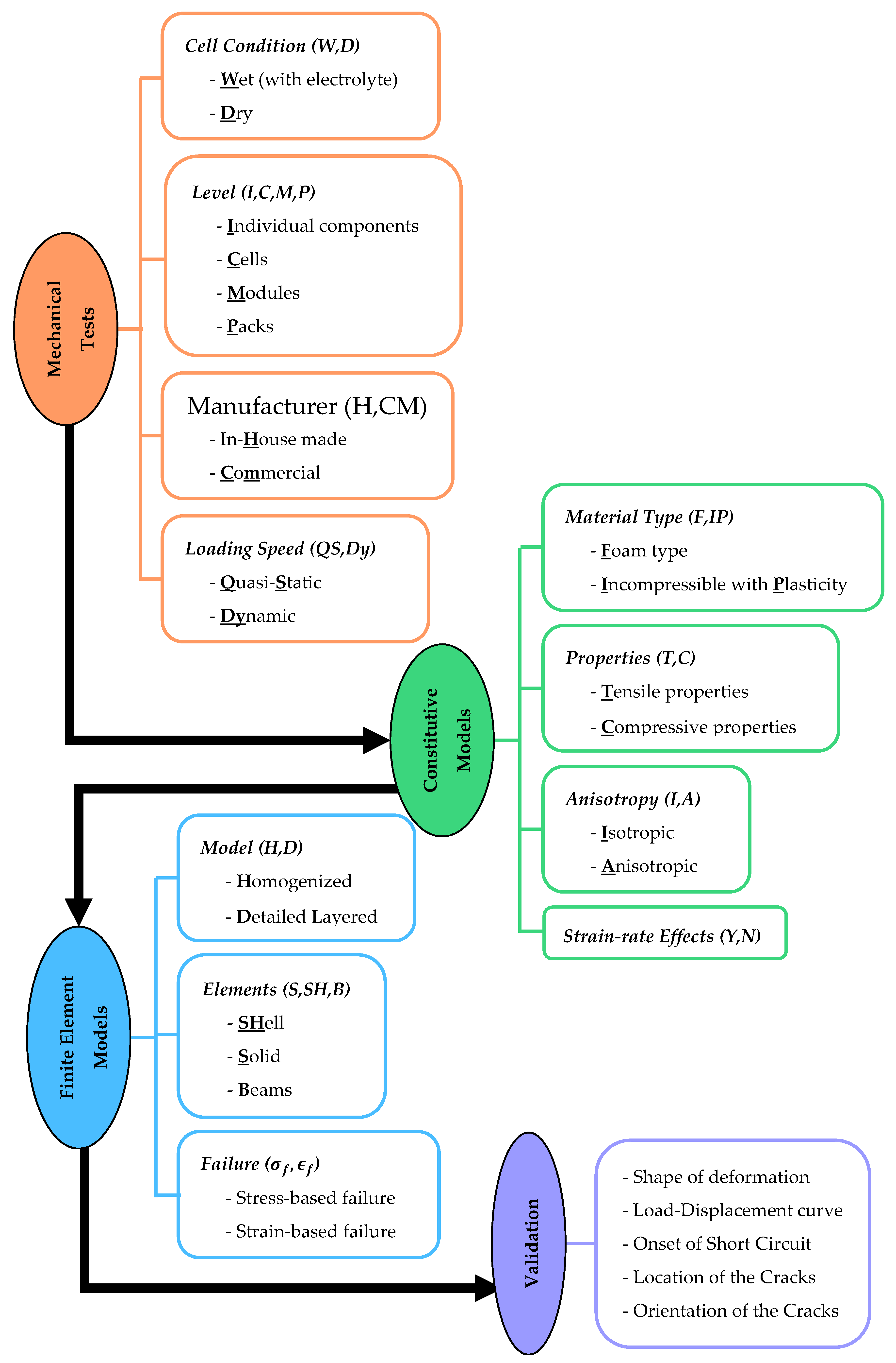
Figure 3.
Experimental setup and deformation of pouched (left) and bare (center) cells. Finite element models are shown in the (right) column. Figures are from the study presented in [9].
Figure 3.
Experimental setup and deformation of pouched (left) and bare (center) cells. Finite element models are shown in the (right) column. Figures are from the study presented in [9].
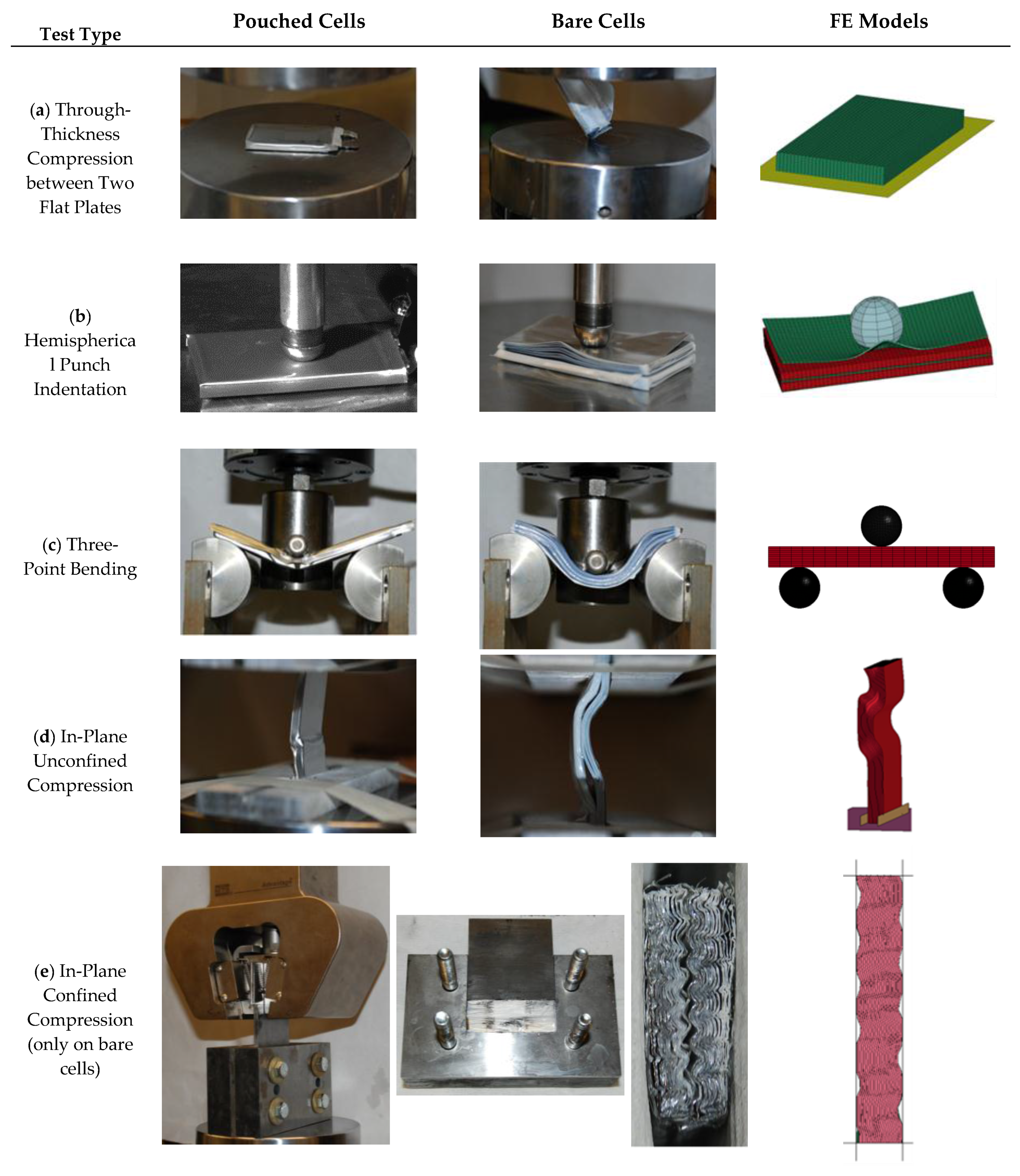
Figure 4.
(a) Typical measurements of force, voltage, and temperature from tests on Li-ion cells, reproduced from [35]. A local peak in force, a drop in voltage, and a rise in temperature indicates a short circuit in the cell; (b) Typical stress-strain curves from in-plane and out-of-plane compression tests on Li-ion battery cells [9].
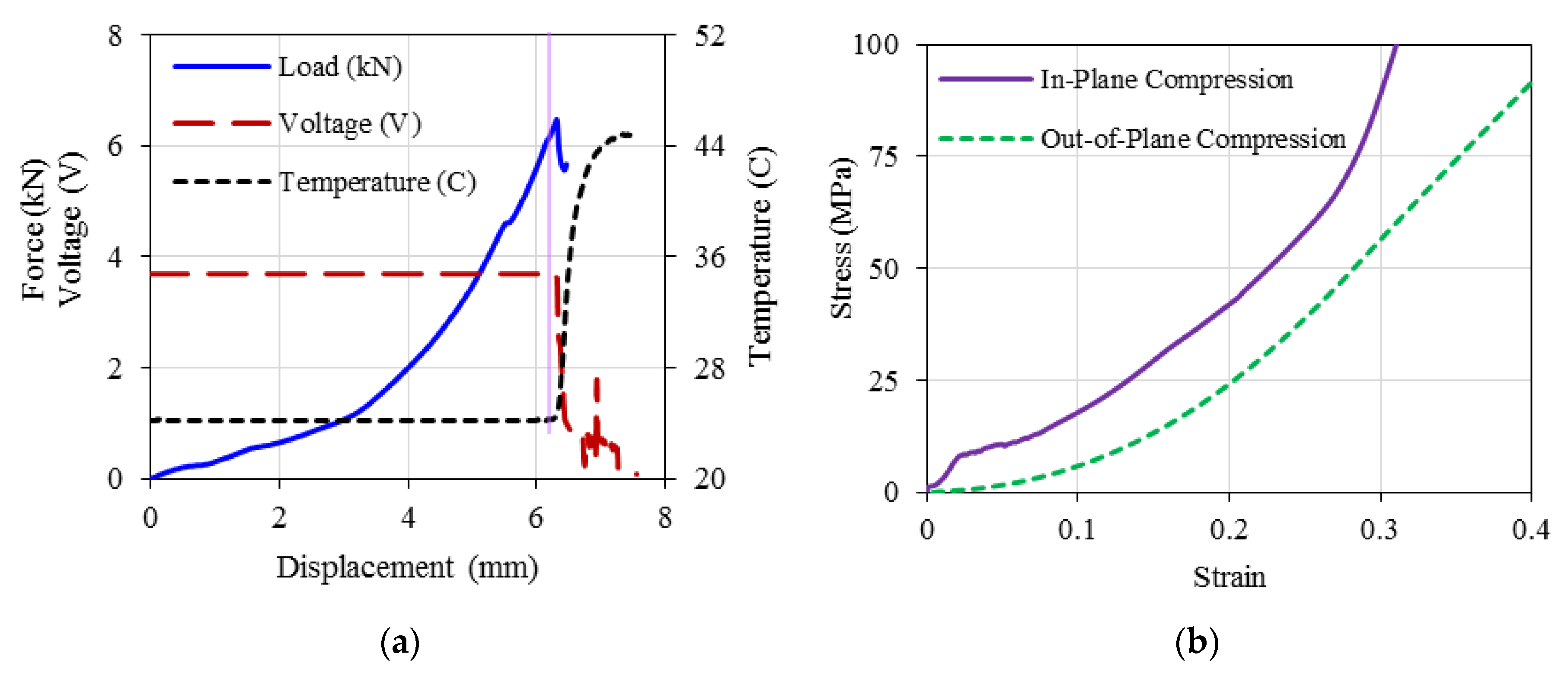
Figure 5.
Experimental setup and deformation of cylindrical cells and the corresponding finite element models. The figures are from the study presented in [35,69]. (a) Lateral Compression; (b) Axial Compression; (c) Hemispherical Punch Indentation; (d) Three-Point Bending; (e) Indentation with Rod
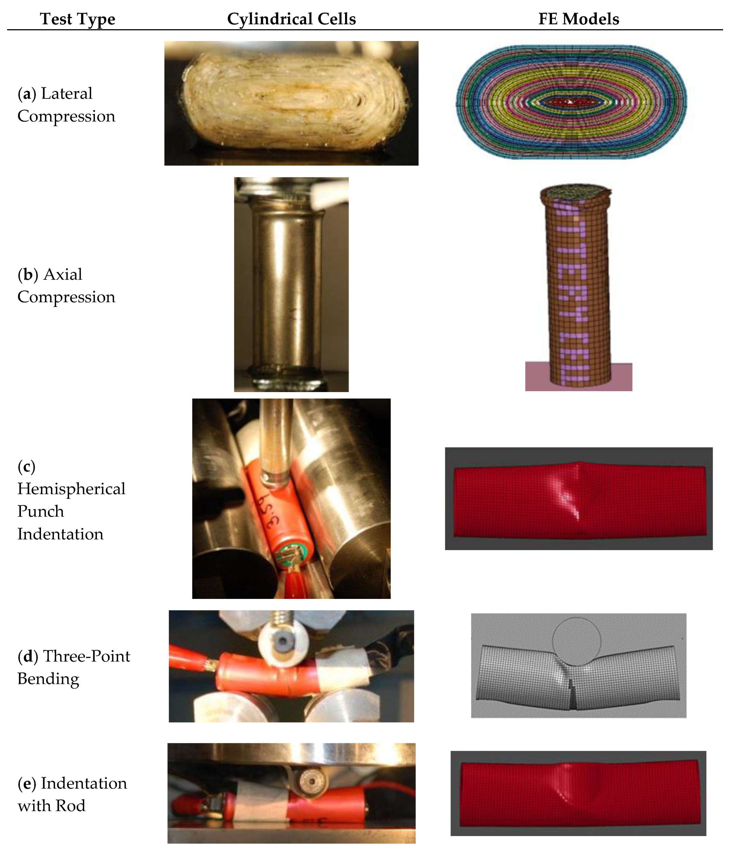
Figure 6.
Experimental setup and deformation of elliptical cells and the corresponding finite element models. The figures are from the study presented in [45]. (a) Lateral Compression; (b) Hemispherical Punch Indentation
Figure 6.
Experimental setup and deformation of elliptical cells and the corresponding finite element models. The figures are from the study presented in [45]. (a) Lateral Compression; (b) Hemispherical Punch Indentation

© 2017 by the authors. Licensee MDPI, Basel, Switzerland. This article is an open access article distributed under the terms and conditions of the Creative Commons Attribution (CC BY) license (http://creativecommons.org/licenses/by/4.0/).
Share and Cite
MDPI and ACS Style
Kermani, G.; Sahraei, E. Review: Characterization and Modeling of the Mechanical Properties of Lithium-Ion Batteries. Energies 2017, 10, 1730. https://doi.org/10.3390/en10111730
AMA Style
Kermani G, Sahraei E. Review: Characterization and Modeling of the Mechanical Properties of Lithium-Ion Batteries. Energies. 2017; 10(11):1730. https://doi.org/10.3390/en10111730
Chicago/Turabian StyleKermani, Golriz, and Elham Sahraei. 2017. "Review: Characterization and Modeling of the Mechanical Properties of Lithium-Ion Batteries" Energies 10, no. 11: 1730. https://doi.org/10.3390/en10111730
Note that from the first issue of 2016, this journal uses article numbers instead of page numbers. See further details here.