Advances in Integrated Vehicle Thermal Management and Numerical Simulation
by
Yan Wang
1,2, 
Qing Gao
1,2,
Tianshi Zhang
1,2,*,
Guohua Wang
1,2,
Zhipeng Jiang
1,2 and
Yunxia Li
3 1
State Key Laboratory of Automotive Simulation and Control, Jilin University, Changchun 130025, China
2
College of Automotive Engineering, Jilin University, Changchun 130025, China
3
China FAW Co., Ltd. R&D Center, Changchun 130025, China
*
Author to whom correspondence should be addressed.
Energies 2017, 10(10), 1636; https://doi.org/10.3390/en10101636
Submission received: 21 August 2017
/
Revised: 6 October 2017
/
Accepted: 10 October 2017
/
Published: 18 October 2017
(This article belongs to the Special Issue Advanced Thermal Simulation of Energy Systems)
Abstract
:With the increasing demands for vehicle dynamic performance, economy, safety and comfort, and with ever stricter laws concerning energy conservation and emissions, vehicle power systems are becoming much more complex. To pursue high efficiency and light weight in automobile design, the power system and its vehicle integrated thermal management (VITM) system have attracted widespread attention as the major components of modern vehicle technology. Regarding the internal combustion engine vehicle (ICEV), its integrated thermal management (ITM) mainly contains internal combustion engine (ICE) cooling, turbo-charged cooling, exhaust gas recirculation (EGR) cooling, lubrication cooling and air conditioning (AC) or heat pump (HP). As for electric vehicles (EVs), the ITM mainly includes battery cooling/preheating, electric machines (EM) cooling and AC or HP. With the rational effective and comprehensive control over the mentioned dynamic devices and thermal components, the modern VITM can realize collaborative optimization of multiple thermodynamic processes from the aspect of system integration. Furthermore, the computer-aided calculation and numerical simulation have been the significant design methods, especially for complex VITM. The 1D programming can correlate multi-thermal components and the 3D simulating can develop structuralized and modularized design. Additionally, co-simulations can virtualize simulation of various thermo-hydraulic behaviors under the vehicle transient operational conditions. This article reviews relevant researching work and current advances in the ever broadening field of modern vehicle thermal management (VTM). Based on the systematic summaries of the design methods and applications of ITM, future tasks and proposals are presented. This article aims to promote innovation of ITM, strengthen the precise control and the performance predictable ability, furthermore, to enhance the level of research and development (R&D).
1. Introduction
The daily life and productivity of people worldwide now suffer great inconveniences brought about by environmental pollution, ecological damage, global warming and greenhouse effects [1,2]. Faced with the dual pressures of energy supply and environmental protection, vehicle manufacturers are dedicated to developing the vehicle integrated thermal management (VITM) systems to satisfy the requirements of performance reliability, fuel economy and human thermal comfort of modern vehicles [3,4,5,6].
The concepts of vehicle thermal management (VTM) were firstly applied in the aviation and space industries, then in the 1970s researchers advocated employing it in the vehicle industry too [7,8]. The modern vehicle integrated thermal management (VITM) system can realize rational and comprehensive control over thermodynamic processes in terms of power system integration [9]. The objects of VITM are various, depending on the different power systems. Hence, for an internal combustion engine vehicle (ICEV), the ITM contains internal combustion engine (ICE) cooling, turbo-charged cooling, exhaust gas recirculation (EGR) cooling, lubrication cooling and air conditioning (AC) or heat pump (HP). As for electric vehicles (EVs), these can be classified into pure electric vehicles (PEVs) and hybrid electric vehicles (HEVs) according to the different configuration mechanisms. For PEVs, the ITM mainly includes battery cooling/preheating, electrical motor, direct current to direct current converters (DC–DC) cooling and heat pump or air conditioning. Besides, the ITM of HEVs, considering the series, parallel and series-parallel mechanisms, combines ICE cooling and electric power system (EPS) cooling [1]. The classification of VITM is shown in Figure 1. Although the power source differs between ICEVs and EVs, the essences of their VITM systems is identical, which can realize fuel economy, emission reduction and energy efficiency promotion via rational, effective and synergetic control over interrelated thermodynamic systems [5,10,11].
With the rapid development of computer technology, there exists more and more commercial software for VITM to analyze and simulate the multiple thermodynamic processes [12,13,14]. For example, the 1D program platform of Flowmaster can analyze the functional parameters on scale of system including flux, pressure, velocity and temperature variations under transient or steady conditions [15]. Compared to analysis of the hydraulic system, the 1D software KULI was developed for thermodynamic equilibrium and configuration matching for thermal dynamic components to ensure the performance of the power system, underhood cooling systems and HVAC [16]. Besides, there are plenty of 3D CFD software programs, which can be easily extendable to structuralized and modularized simulations. It is noted that LMS ImagineLab has developed AMESim, which can offer 1D/3D simulation to model and analyze multi-domain of intelligent systems, which can predict the hydraulic, pneumatic, electric or mechanical behavior of the system [17,18].
With the boom in visual simulation and computation, the integration of design, evaluation and manufacturing of vehicles with optimal overall performance is being implemented. Thus, scientific research institutions and vehicle manufacturers worldwide have attached much more importance to vehicle ITM. In 1996, the United States Department of Energy launched an extensive cooperation with automobile companies including Chrysler, Ford, and GM and formulated a vehicle energy-efficiency scheme for ITM with power system and HVAC coupling [19]. Thus, vehicle ITM has been regarded as one of the most potential and important vehicle technologies in the 21st century. The German Aerospace Center (DLR) worked with the British company Claytex Inc. to develop a VITM for an ICE, gearbox, electronic control unit based on simulation [20]. The South Korean carmaker Hyundai carried out VITM with multilevel control over coolant temperature of radiator and fan. To improve performance and mileage, in 2011, the Yokoyama from the Japanese company Hitachi developed a VITM system for electric vehicles called the “Thermal Link System”, which can realize heat transfer from the exterior to the interior with a heat-pump cycle, and its interior heating is characterized with the utilization of the waste heat from the motor and the inverter [21].
Compared to the developed countries, VITM development in China is still at a preliminary stage. Funded and supported by major projects, such as the national 863 plan, the national Natural Science Foundation of China (NSFC) and National Science and Technology, etc., Chinese scientific research institutions have explored ITM extensively and comprehensively to promote energy efficiency and light vehicle weight, and to strengthen precise control [22]. To stimulate the development of ITM in China, the Outline of the 13th Five-Year Plan clearly states the necessity of vehicle ITM for energy conservation and environmental protection. Hence, the VITM technology has been identified as one of the key technologies for sustainable and healthy vehicle development.
In order to pursue high efficiency and light weight automobile, as the important part of modern vehicle technology, the power system and its thermal management have attracted wide attention. Regarding ICEVs, ITM contains ICE cooling, turbo-charged cooling, EGR cooling, lubrication cooling and AC or HP. As for EVs, ITM mainly includes battery cooling/preheating, power electronics and electrical machines cooling and heat pump air conditioning. With the rational and comprehensive management of these mentioned thermal components, the modern VITM can realize collaborative optimization of multiple thermodynamic processes. Furthermore, with the booming in computer-aided calculation and simulation, especially for complex systems, the 1D programming can correlate multi-thermal components, with 3D simulations can develop structuralized and modularized designs, additionally, 1D/3D co-simulation can virtualize the simulation of various thermo-rheological behaviors. This article reviews the advances in modern vehicle thermal management and its numerical simulations, then presents some future tasks and proposals. This article aims to promote innovation in vehicle ITM, strengthen precise control and performance predictable ability, and further improve the level of research and development (R&D) in this area.
2. Advances in VTM
According to their different power sources, vehicles can be mainly classified into three groups: ICEVs, PEVs and HEVs [1,23], hence the research on the basic component s of vehicle thermal management (VTM) systems are quite different to some extent. In ICEVs, ITM involves ICE cooling, turbo-charged cooling, EGR cooling, lubrication cooling and AC or HP. Figure 2 presents a typical thermal management schematics diagram of an ICEV. EVs include PEVs and HEVs. In PEVs, ITM mainly includes battery cooling/preheating, electrical machine (EM) cooling and heat pump air conditioning, while in HEVs, the thermal management objects include the air conditioning system and EPS, which mainly includes battery cooling and electric machine cooling. Figure 3 shows a typical thermal management schematic diagram of a PEV. Besides, the energy characteristics of HEVs combine an internal combustion engine (ICE) and an electric power system (EPS). Figure 4 is a typical thermal management diagram of a HEV.
2.1. Thermal Management for ICEVs
2.1.1. Basic Engine Cooling
Investigations on engine cooling has been performed since early in the 19th century [24,25,26,27]. In 1958, Kling proposed a method for guiding radiator selection, which adopted a experiential design method to maintain the internal combustion engine body operation within the proper temperature range [28]. Taken experience as reference, this method fails to present accurately the matching relationship between cooling air flow rate and radiator heat dissipation capacity, resulting in systematical overcooling or overheating problems. Meanwhile, the experiential design method lacks predictabilty capacity and analytical accuracy [29,30].
An engine thermal management system providing precise cooling has been the trend to promote better dynamic performance and fuel economy [31,32,33]. In 1999, scholars from Bath University in the UK pointed out that precision cooling concept was at the foundation of recent ideas for advanced engine thermal management and employed electric water pumps to realize electronically control with low coolant flow rates [34].
In order to improve engine thermal system management and fulfill the need of car manufacturers, VALEO developed the engine cooling system named THEMIS™ that included intelligent electrical fan, water valve and pump components and was used on four Mercedes A Class automobiles [35,36]. It was also shown that the adjustment of fan speed according to the cooling airflow variables could reduce fuel consumption by 2~5% and CO emissions by 20% [37,38]. Since 2003, Wagner and his colleagues from Clemson University have focused on investigation of electric temperature controlled thermostat valves in order to replace conventional wax valves [39]. The electric temperature controlled thermostat valve allows different temperature settings informed by the engine control unit (ECU) to realize real-time adjustment to the ratio flow to the radiator and to the bypass circuit [40]. With the emergence of electrical components, thermal management for engine cooling tends to be electrified nowadays, featuring modularization, integration and intelligence [41,42,43,44].
2.1.2. Combination with Other Cooling Circuits
In order to solve the ICEV emission problem, there are more and more heat exchangers, likewise, EGR coolers, charge air coolers (CACs), lubricant coolers and so on are being used, located in the compact underhood [45,46,47]. As for EGR, which can lower the in-cylinder combustion temperature to reduce pollutant emissions, its use emerged in the early 1970s [48,49,50,51]. The effects of internal fin width, wave number, inscribed circle diameter and upwind distance on the heat transfer performance of EGR coolers have been a recent research focus [52,53,54,55]. Besides, CACs are another extraordinarily effective method for increasing ICE power density, which have been studied since the 1980s [56]. Nowadays, with the promotion of liquid cooling applications, liquid cooling CAC have now replaced the conventional air cooling CAC, as liquid cooling CAC exhibits full boost power and a faster acceleration response, as well as better fuel economy compared to traditional air cooling CACs [56,57,58,59], and thus the overall packaging volume and compartment weight could be reduced [60,61]. Additionally, to lower the lubricating oil temperature during cold start up, oil cooling systems began to be adopted in the 1990s [62,63], They are beneficial to reduce NOx and HC emissions [64,65]. However, by placing together all the above thermal systems in the limited underhood space, significant amounts of heat will be expelled to the ambient [66] and would be very difficult to fulfill their requirements with a single circuit and to match their different thermal needs properly with each other [67,68].
To solve the mentioned bottleneck problems and improve the underhood heat dissipation capacity, it is urgent to search for a rational and effective ITM for ICEV design such as split cooling systems or multi-circuit cooling methods. Split cooling is helpful to deal with the packing of the unions of engine cooling and additional cooling systems within the existing engine and within the available vehicle underhood space [69]. Split cooling circuits usually employ two branches which operate at two different temperature levels in accordance with the established rules. The typical split cooling system—UltimateCooling™ system, which was introduced by VALEO in 2005 [70], could renew the layout of the engine cooling system [71].
The temperature levels of traditional single cooling circuits are always inappropriate for optimum engine, oil and charged air cooling. Moreover, the irrational design of scaling up heat exchangers and fan size not only occupies excessive space, but may also not suitable for actual operation conditions. Thus multiple cooling circuits allow reorganizing all these thermal requirements joining different functions more efficiently. Kim and Song [72] presented and patented the proposal to rearrange optimum temperature cooling, according to the different temperature demands among thermal engine requirements (higher temperature level) and oil and charge air requirements (lower temperature level). Therefore, this thermal management with two cooling circuits operating at different temperatures can increase at steady operating conditions overall engine efficiency and power. Cipollone [73] also introduced a mathematical investigation of engine double-cooling circuits with multiple temperature levels. The double-cooling circuit configuration has two cooling loops, one is a high temperature loop that ensures the cooling for the engine, oil, and EGR, and the other one is the low temperature loop that ensures the cooling of refrigerant and CAC. Through evaluations of the performance, this advanced thermal management did allow improvements in terms of engine warm-up, fuel savings and air boosting.
2.1.3. Coupling with Air Conditioning
As for ICEVs, the thermo-dynamic systems, such as engine cooling system, CAC, EGR cooling system, oil cooling system and AC, are packed in the reduced space available under the hood. The interactions between these subsystems are so complex that this presents new opportunities for integrated thermal management (ITM) systems, which combine AC with VTM for ICEV, to fulfill the different system operation temperature requirements. In recent years, for the purpose of improving vehicle thermal management and making the whole system more efficient, accurate and integrated, VITM technologies have been further explored, especially in subsystem integration such as for the thermal system and AC system, etc.
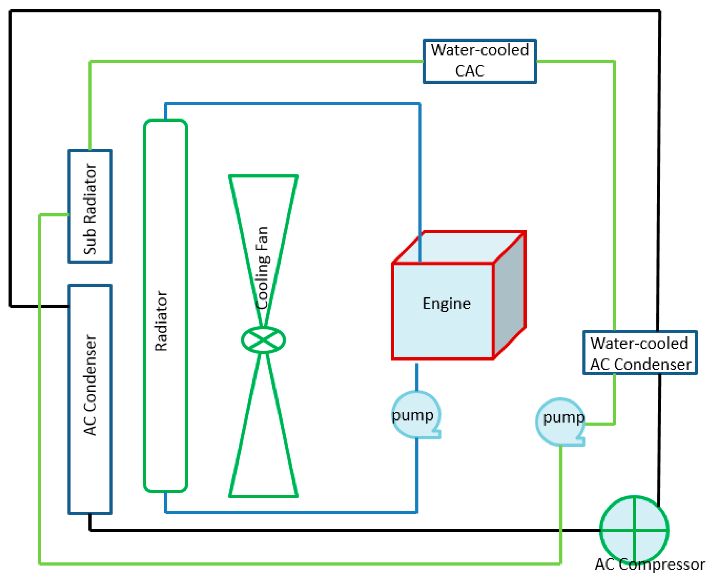
Thermo-dynamic components configuration optimization is not only an efficient method but also a significant design feature for ITM to improve vehicle fuel economy [74]. Compared to the conventional axial and side-by-side systems, a novel high performance radial compact cooling system (CCS) was developed by Soldner in 2001 [75]. To achieve better performance with less fan power and occupy a smaller space, General Motors Corporation worked with Delphi Automobile Systems Inc. [76] to propose a new condenser, fan, radiator and power train cooling module packaging configuration named CFRM. To relieve the phenomena of rising heat rejection, electric control of VITM was introduced to a light duty diesel truck in work supported of the National Automotive Center in 2005 [77], featuring electric water pumps, an electric thermostat, electric fans, secondary cooling systems for the transmission and EGR, and a liquid-cooled charge air cooler. This advanced thermal management system allowed for individual control of different cooling circuits. In 2012, Mathur developed a new ITM called “SLIM” [78]. Its schematic diagram, shown in Figure 5, includes a liquid-cooling AC condenser designed for cooling superheated refrigerant vapor, as well as a sub-radiator to provide cooling to the CAC and condenser. What’s more, the development of electric control stimulates the multiple cooling circuit application [79,80,81,82]. As recommended by Song from the Hyundai-Kia America Technical Center Inc. in 2014 [83], the integrated LTC loop proposed in the secondary cooling strategy with the configurations of connected in series and parallel can meet different thermal components function requirements.
2.2. Thermal Management for Pure Electric Vehicle
2.2.1. Battery Cooling/Preheating
Restricted by the narrow space and complicated driving and operation conditions, the battery heat generation in modern electric vehicles is often excessive [84,85]. This can lead to a sharp increase in the battery packing temperature and even thermal runaway. To optimize battery packing safety, it is desirable to operate Li-ion battery packing in a suitable operation temperature range of 20~40 °C [86]. Thus, it is necessary to conduct thermal management for battery cooling/pre-heating [87] with consideration of the number of cells, geometry and vehicle mass distribution [88]. It is generally well-known that considering the different cooling media, the battery thermal management (BTM) approaches can be summarized as follows: air cooling, liquid cooling, heat pipes and PCM cooling [89,90,91,92,93,94]. Different BTM methods each have their limitations and merits [93].
Air cooling is the simplest approach in terms of mechanical structure. Forced-air cooling can mitigate the temperature rise, but it will inevitably cause a large non-uniform distribution of temperature in the batteries during severe driving conditions and at high operating temperatures [95]. Zolot et al. evaluated the air cooling thermal management of the battery pack applied in the Honda Insight and Toyota Prius [96,97]. They deemed that air-cooling is not convenient for battery pack pre-heating in cold weather. Sabbah pointed that air cooling for battery heat dissipation is sometimes invalid. He also simulated and experimented with an air forced convection cooling method, and the results showed that battery temperature variation increased with air velocity, but even though air velocity continued to increase, the battery temperature was not controlled below 55 °C when the ambient temperature is 45 °C and the discharge rate is 6.67 °C [94].
Then, a novel solution by using PCM for BTM was proposed for EV applications. PCM battery thermal management system was firstly demonstrated by Al-Hallaj and Selman [98]. Then, Kizilel designed a passive BTM, which used PCM to cool compact type 18650 batteries under high current and temperature conditions, and the results indicated that the battery temperature was kept in a reasonable range [89]. PCM cooling and heat pipe cooling belong to the passive controlling methods and battery pack weight and volume will increase at different levels. Actually, cost, passive control, materials election and volume expansion of PCM still restrict the application in EVs, and these problems need to be solved as a next step [99].
Wu et al. adopted two heat pipes with aluminum fins attached to the cylindrical battery wall to mitigate the temperature rise. Their experimental and simulation results showed that the temperature rise is significantly reduced by heat pipes [100]. Jang adopted a loop cooling method for high efficiency cooling. The system combined a heat pipe and air cooling at the same time and its heating section was distributed on the surface of the battery with the fan blowing the air flow over the condenser section. Their experiments showed that the battery operating temperature was under 50 °C with pure water as medium and 45 °C with acetone [101]. Currently, many heat pipes for battery cooling investigations focus on weight reduction and performance improvement. Generally, there are several primary methods that include using lightweight metals, improving the wick structure, minimizing the size of devices and changing the working fluids, etc. [100,102,103].
Compared to the BTM mentioned above, though the liquid cooling system is complex and has potential leakage problems, it is always effective and flexible for integration so liquid cooling can be a current popular method in battery pack thermal management applications. In contrast to the Nissan Leaf air cooling BTM system, liquid cooling thermal management systems are more effective for integrate, and have shown significant progress in reducing the response time during cold start up.
Aiming to keep the battery operation within the optimal temperature range, Yuan studied a liquid cooling/heating BTM with structural geometry optimization [104]. By combining simulation and optimization, the cooling plate surface temperature can be reduced by 2.61 °C, so as to improve the battery dynamic performance. Currently, the Chevrolet Volt, and Tesla Model S battery packs employ liquid cooling/heating battery thermal management adapted to various ambient conditions [105,106,107]. Chacko et al. evaluated the performance of liquid cooling battery pack thermal management systems and concluded that liquid cooling/heating would be one of the most promising means to achieve uniform battery temperature distributions thanks to its active control [108,109]. Jarrett designed thin metal battery cooling plates, which included serpentine-channels. Heat would be conducted from the batteries into the cooling plate, and transported away by the coolant. The geometry of the channel had a significant impact on the operating characteristics of the cooling plate, which included route, width, length, etc. The computational fluid dynamics (CFD) optimization results implied that both pressure and average temperature can be satisfied without compromising the temperature distribution uniformity [110].
2.2.2. Electric Machine Cooling
Electric machines (EMs) are critical components used for traction and energy supply of PEVs and HEVs, whose temperature rises are due to energy losses in their windings and iron core [111]. Due to the higher loss densities for its high-speed and higher power densities, this represents an important challenge in thermal management of machines [112,113]. The thermal management for the cooling medium of E-motor thermal management systems mainly includes air cooling and liquid cooling using water, oil and so on [114,115,116].
As for air cooling for E-motors, it is necessary to adopt a suitable cooling structure to increase the cooling airflow rate [117]. Nakahama studied numerically the cooling airflow in a unidirectional ventilated open-type motor for EVs in 2006 [118]. They led the airflow in a motor through a ventilation path outside the stator iron core inside the frame and proposed a new optimal structure to improve E-motor cooling performance. To study the effect of optimal geometry on effective cooling, in 2011, Kimotho investigated and evaluated the thermal management of a 1.2 kW brushless DC permanent magnet motor [119]. He introduced a rectangular fin geometry on the motor housing. The simulation result showed that with a 10 mm deep fin on the housing, the heat transfer rate could be enhanced and the winding temperature could be reduced by up to 15%.
Air cooling friction losses may lead to a decrease of electric power system efficiency, so liquid cooling thermal management applications have attracted extensive interest for its better thermal conductivity [120,121]. Compared to air cooling, this guiding structural liquid cooling thermal management method for E-motors can ensure high performance with a heat transfer coefficient increase by 60% [122]. Zheng [123] investigated a water cooling system with 12 water channels evenly distributed in the motor housing for the four quadrant transducer prototype machine of HEVs to provide a reference for parameter options. Besides, Park [124] applied a liquid cooling system for the power electronics of electric vehicles, which is comprised of cold plates, liquid pump, radiator and a plumbing network. With layout optimization he computed in his study the cooling performance including liquid flow rates, pressure drops, and maximum temperatures of the cooling system by numerical simulations.
2.2.3. Coupling with Air Conditioning
As for PEVs, although heat pump systems display higher performance characteristics compared to conventional AC and electrical heating systems and is gaining wide utilization, there still exist some problems or practical issues to be solved urgently [125].
The first is to deal with HP operation with lower COP under cold environmental conditions. In 2004, Meyer et al. employed a new high pressure heat exchanger to replace the HP evaporator and condenser in order to prevent the deterioration of R134a heat pump performance under cold conditions [126]. Hosoz and Direk’ revealed in 2013that heat pump operation could supply adequate heating capacity to the compartment only in mild weather conditions when the working fluid is R134a [127]. The system performance would decrease dramatically with decreasing outside ambient temperature. They suggested redesigning the exterior and interior heat exchangers and using a higher temperature heat source, which might be the options for improving heating mode performance.
The second one is to redesign the parameter optimization and performance matching of thermal components included HP systems and EPS. Cardol et al. [128] studied the DC/AC converter and the compressor of HP, and proposed a semi-empirical model for the prediction of the compressor work, mass flow rate, and discharge temperature. Kowsky [129] suggested in 2012 a new heat pump system which used a coolant to replace refrigerant passing and cooling for batteries, motors, and PCU, etc. Its refrigeration cycle was more compact for reduction of refrigerant and flow path.
Meanwhile, in order to maintain EV applications with safety, stable performance, mileage and energy savings, which are required of EV development, VITM technologies, especially in subsystem integration such as BTM systems, E-motor systems and HVAC systems, etc, should be further investigated. In 2011, General Motors designed an ITM system for the Chevrolet Volt electric vehicle. The VITM employs a 3-way valve to switch operating modes to cool and heat the battery. There are three coolant flow paths. As for the flow path “A”, it permitted fast heating of the lithium-ion batteries under low temperature conditions. The flow path “B” was used for cooling the overheated batteries with coolant to dissipate heat to the R-134A refrigerant in the battery chiller. When the batteries operated stably, the coolant could flow into path “C” and then back to the pump with heat dissipating in the battery cooling radiator [130]. A sketch is shown in Figure 6.
PEV has complex thermal management requirements not found in conventional vehicles, such as cabin conditioning, the battery pack and power electronics and electric motor subsystems that all require thermal management. In order to satisfy the various requirements and to improve electric drive vehicle range, National Renewable Energy Laboratory (NREL) researchers conducted an initial feasibility study to predict combined fluid loop (CFL) of ITM through software simulation and experiment since 2012 [131]. Figure 7 presents a CFL VITM technology that unifies the cabin air-conditioning and heating, battery cooling, and EM cooling into a single liquid coolant-based system with separate hot and cold fluid streams that are directed to the thermal components as required.
The unified system has a single heat exchanger at the front end of the vehicle instead of conventional multiple heat exchangers, which can minimize the area and number of heat exchangers at the front end of the vehicle and has the potential to reduce the aerodynamic drag of the vehicle. It can be expected that with this novel VITM, the electric drive vehicle range can be extended more than 9% [132,133,134].
2.3. Thermal Management for HEVs
2.3.1. ITM for Hybrid Power Sources
HEVs mainly include three mechanism designs: series, the parallel and parallel-series designs. In the series design, the vehicle’s wheels are only rotated by the electric motor, which provides driving power, without the ICE [135,136]. The ICE is only used as a generator which supplies electrical power for the electric motor (EM). The battery packing is for excess charge storage [137]. In the parallel HEV design, both the ICE and the EPS, including battery pack and EM, etc., can provide driving power to drive the vehicle’s wheels independently or through mechanical coupling [138,139]. Finally in the parallel-series hybrid design the vehicle has the flexibility to operate in either series or parallel mode. No matter what the mechanism design is, it is important to develop an efficient ITM for the hybrid power sources for HEV coupling of ICE and EPS aiming to improve vehicle dynamic performance [140,141,142].
Based on the operational temperature characteristics of the thermal source components in HEVs, in 2004, Wang designed a cooling system embracing high and low temperature circulation loops to separate the high temperature components from the low temperature ones [143]. This ITM featured a double cooling circuit that can improve the coolant temperature of high temperature circulation, radiator heat transfer efficiency, as well as shorten the response time when cooling or preheating [144,145]. To make a trade-off between fuel economy and configuration complexity, an instantaneous optimal control strategy of ITM is then developed and employed by Lang and Kitanoski, in 2007. The ITM featured three different cooling circuits to meet different energy sources’ cooling requirements. The first one was an ICE cooling circuit with a temperature level roughly set at 95 °C. Additionally, the cooling circuit for the electrical system had a limitation of 75 °C. The last one was a battery cooling circuit. By co-simulation, the ITM behaviors were analyzed under various ambient conditions and vehicle loads [145]. The ITM design for a heavy duty military Series Hybrid Electric Vehicle was conducted by Park [146], which included a vehicle cooling system (VCS), climate control system (CCS) and vehicle powertrain system. Together with research on the heat transfer, fluid mechanics, and thermodynamics, the authors simulated CCS parameter performance, including coolant pumps, fans, radiators, thermostats, and heat sources, to control the battery thermal behavior stably and reliably.
2.3.2. Coupling with Air Conditioning
As the result of the different power distribution and transmission between mechanical and electrical segments, the various power architectures possess various coupling characteristics of power flows among the power devices [147]. With the different integration of mechanical and electrical components, the ITM for HEV coupling air conditioning has been identified as a critical issue [148,149,150].
To improve operating performance and reduce energy consumption, in 2010, in an annual merit review at the U.S. National Renewable Energy Laboratory (NREL), Bennion applied the developed the analysis approach to the electric drive thermal management system to investigate potential integration opportunities with ICE and HVAC thermal management. This proposed VITM can be divided into two cooling loops, as shown in Figure 8. The high temperature coolant loop serves for the engine and electric drive system and the low temperature coolant loop was for HVAC and electric drive systems. This provided an integrated approach to quantify the transient and continuous thermal requirement of individual components under various ranges of driving conditions [151].
In 2014, supported by the U.S. Department of Energy, Cao demonstrated an integrated control strategy for the thermal management of parallel HEVs, which was equipped with three fully independent cooling loops that each utilized their own separate radiator. The specific engine cooling loop to cool a 2.4 L E85 engine is shown in Figure 9. The battery cooling system had two cooling loop circuits with a 2-way valve to distribute coolant through the radiator or the battery chiller to transfer heat to the AC system. Finally, the motor/MCU cooling loop was dedicated to prevent the important power electronics from overheating during use. It can be concluded that the VITM is suitable for real-time vehicle operations and energy conservation [152]. Additionally, researchers from Clemson University [153] investigated ITM for a hybridized mid-size truck for military applications and its control algorithms. The mentioned cooling system featured an electric-mechanical compressor, coolant pump and radiator fans, as well as a series of controllers. It can effectively regulate the battery pack, electric motors, and the internal combustion engine temperature through controlling the refrigerant compressor, coolant pump, and cooling fans. As a result, it can not only minimize the temperature fluctuations of the battery and ICE, but also reduce the overall auxiliary power consumption of the cooling system by 45% compared to a conventional cooling control method.
In conclusion, for the thermal management of a PHEV, it is necessary to understand the performance and efficiency of the climate control system, which will influence the vehicle’s sustainability objectives [154]. What’s more, the designer should establish the ITM concept composed of air conditioning and heating system, EM cooling system, battery cooling/preheating system and ICE cooling system, no matter whether electricity or waste heat of hybrid power sources coupling ICE, EPS and AC will be utilized to construct an ITM.
3. R&D of Numerical Simulation for VITM
3.1. Overview
Since performing an experiment cannot provide optimized operation for vehicle pre-design and may be costly, an alternative method is to employ numerical computation and simulation to design a scientific and rational strategy for VITM [155]. With the development of synergy optimization for multiple thermal-dynamic components in the vehicle, a variety of numerical methods based on computational technologies have emerged, including one dimension simulation (1D), three dimension simulation (3D), and 1/3D co-simulation [156,157]. Compared to experimental bench research, the computational numerical simulating technology have the advantages of lower cost, higher efficiency, more convenient operation, as well as being less time-consuming for VITM research [158]. Thus, numerical computation and simulation have been broadly applied for VITM [159,160].
In order to offer a flexibility strategy for VITM with rapid construction and modification, a transient capability 1-D modelling approach is identified to be applicable and convenient [161]. 1D simulation software requires less computation resources and has good prediction precision to satisfy the demands of actual engineering calculations. Typical 1D program commercial software includes programs such as AVL BOOST software, AMEsim, GT-SUITE, KULI and so on [162]. 1D simulation approaches have been proven to be very powerful and efficient when dealing with sophisticated cooling systems. They can perform thermal analysis of engine cooling or air conditioning systems that incorporate several different components involving radiators, condensers, evaporators, thermostats, coolant pumps, batteries and different cooling cycles, etc.
Additionally, 3D numerical simulation has advantages in reflecting the details thermo-dynamic and aerodynamic complex characteristic of ICE or EPS, like heat transfer, air flow velocity and temperature distribution, under various driving and ambient conditions [163]. There exist a variety of 3D program commercial software packages, such as Radtherm, Fluent, FRIE and STAR-CD. With the development of 3D numerical computation and simulation, it has gradually replaced the earlier experiential design methods of engine cooling systems, promoting the accuracy of matching cooling air flow rates with radiator heat dissipation capacity, as well as solving systematical problems of overcooling or overheating [164]. Every approach has its own merits and demerits [165,166]. The 3D simulation approach simulates the distribution of temperature, velocity and pressure field and it also facilitates the structuration design and optimization, but 3D simulation actually has difficulties in describing the relevance between multi-thermodynamic cycle systems, which can be easily realized by the 1D approach. Likewise, the 1D simulation approaches can give a representation of internal mechanisms for different cycles, however, they have the drawback that they are limited to simulating the airflow distribution and real-time thermal-changes caused by structural optimization [167].
To satisfy the requirement of both structural optimization and describe the relevance of multi-thermodynamic systems simultaneously, the combination of 1D and 3D co-simulation has gained significant attention [168]. Considering a real module simulation, such as the engine, pipes, bumper, crossbars, shroud, fan, battery, etc., which interact with the airflow field and might result in flow separation, cross flows, increased mixture, recirculation and pressure drop, etc., the 1D and 3D co-simulation is an approach that can integrate the advantages of the two simulation approaches while simultaneously eliminating the drawbacks [165,166,167,168,169].
3.2. Co-Simulation for Internal Combustion Engine Vehicle
Taking the coupling solution of ICEV engine compartment thermal management as an example [170], initially, 3D modelling is to predict the airflow distribution features, temperature field, and velocity field and so on. Then, the results are fed into a 1D program as boundary parameters. Correspondingly, the 1D model will feed the 3D model with boundary conditions, such as heat rejection on the air side or liquid side. This compliant technique of coupling two different dimension methodologies in a coupled manner can eliminate the need for repeatedly calculating 3D solutions for every vehicle operating condition. As reference and guidance for thermal management system design, the modeling approach is easily extendable to predict the effects of variations in any condition and improve the accuracy of the simulation calculations [171,172]. During the process of 1D and 3D co-simulation, a problem that has to be resolved is the dependency on input data [173]. Co-simulation usually works as a closed loop simulation. By providing the transient boundary conditions obtained from the 1D model to the 3D domain and then feeding the output results of the CFD simulation back to the 1D environment, consequently, the impact of the results obtained during the CFD simulation on the rest of the domain can be captured [174].
When Stroh et al. [172] analyzed the thermal efficiency of the engine cooling package as well as the HVAC system with 1D software (KULI) and various 3D approaches, they used KULI to transform the heat rejection based on experimental data into non-dimensional values and facilitated the 3D simulation and predictions for real-size components. It was further reported in [175] that a co-simulation employed the “CFDLink” to ensure data exchange in each numerical iteration step of 1D and 3D computation cycle. What’s more, Kumar [4] applied the co-simulation of KULI, Fluent and the Software of Radtherm to study the engine cooling performance by evaluating radiator heat dissipation and top hose temperatures. Among them, the results of the 3D simulation were fed to KULI with boundary conditions such as convective coefficients to simulate the engine cooling system. To determine the thermal and mass flow distribution of a complete vehicle, ref. [176] gave an underhood co-simulation of 3D Star-ccm+ and 1D GT-SUITE. In this research, a 1D model of the cooling system was used to get the non-uniform boundary conditions for transient CFD simulations. Long [177] employed a FLUENT and KULI co-simulation approach to analyze the cooling performance of the cooling system of a heavy vehicle. In his study, a 3D virtual wind tunnel experiment model was conducted in FLUENT to evaluate the original cooling system and the integrated cooling system. Then the velocity matrix obtained from the 3D virtual wind tunnel experiment was imported into the KULI software to analyze the cooling performance differences between the original system and the integrated system. The conclusion was that the cooling performance of the integrated cooling system was superior to that of the original cooling system.
Thus, it can be concluded that the 1D and 3D co-simulation approach has great potential to predict ITM for ICEV with acceptable accuracy and can improve ITM cooling performance [166,178]. Shen [179] discovered that the flow field of the rear engine cabin was much more complicated and the error was much larger if only using the 1D model directly. He also pointed that the 1D and 3D co-simulation was superior for obtaining much more accurate results in the calculation for rear engine ITM. To explore the performance of the cooling system of a new ICEV after adding an air baffle, to change the rear structure of the bumper to improve the cooling efficiency of air induction, Liang [180] studied the 1D, 3D and joint 1D/3D simulation, respectively. The results showed the superiority of joint 1D/3D simulation in VITM analysis, which could distinguish that the cooling performance improvement of cooling airflow passing through the radiator increased by about 4.2% and the outlet coolant temperature of engine was reduced by 6.1 °C. Further research was conducted by Dimitriou [181] involving an ITM for a complex cylinder-to-cylinder EGR distribution structure of an internal combustion engine. The 1D/3D co-simulation could be a more appropriate solution through the comparison with an uncoupled simulation study. Because a small change in the initial conditions could have impact the output results of the 3D simulation, a validation as needed for the initial boundary conditions, but in the co-simulation study, a boundary condition exchange between 1D and 3D models can eliminate this problem. As the conventional CFD analysis for underhood thermal management for ICEV is quite time-consuming because of the complex geometry and flow distributions, the alternative of 1D/3D co-simulation for a full-scale model was introduced to reduce the analysis and design cycle time [182,183,184].
3.3. Co-Simulation for Electric Vehicle
The distribution and uniformity of temperature is critical to the life-span and performance of a battery pack, therefore accurately modeling the complete thermal system is important [185]. When the battery temperature distribution is very uneven, or the temperature is too high or too low, it may lead to damage to the battery and even cause security problems. Therefore, the ITM for EV have become the core technologies of lithium-ion battery development. So far, by means of 1D/3D coupled simulation methods, the heat generation and dissipation of battery discharging and discharging can be modeled and analyzed [186,187].
In 1993, the researchers Newman [188] proposed 1D lumped parameter models that assumed that the positive and negative electrodes of the battery were homogeneous spherical granular porous media. Based on the porous electrode theory and the 1D Butler-Volmer dynamic equation, they described the electrochemical reaction at the solid electrolyte interface (SEI). In addition, according to the Fick law, they could analyze the diffusion process of lithium ions inside the electrode [189,190]. Additionally, they applied the concentration diffusion equation to get the lithium-ion transportation in solid phase electrodes, liquid electrolytes and SEI [191]. The mentioned 1D lumped parameter models then were combined with 3D CFD simulation, through the coupling simulation of electric-thermal and chemical parameters, the researchers realized a representation and prediction of the spatial distribution of the concentration of lithium ion, liquid phase potential and temperature in the processes of charging and discharging [192]. In order to save computation time, a simplified co-simulated semi-empirical electrical and thermal model was proposed by Newman and Tiedemann [193,194], which assumed that the inner electrolyte cannot move [195]. After tests of battery discharging at various rates, the U-I polarization characteristic curve could be obtained and transformed into a specific linear expression with slope and intercept, then it was fed to the 3D CFD computation as a boundary condition [196,197]. Gu [197] and Kim [198] then adopted this co-simulation approached to study the electro-thermal reaction mechanism of heat generation, and what’s more, they conducted a modification to the slope and intercept of linear expression at room temperature of 25 °C and low environmental temperature of 0 °C.
The direct 3D simulation for ITM of EV may have the disadvantage of a lack of control strategy [199], but the 1D and 3D co-simulation can be compensate for integration with ITM structural optimization and its real-time control, which can eliminate the deficiency in prediction and insufficiency of the hardware design for EV ITM [164]. Wang. C [200] has proposed a method of 1D and 3D coupled-simulation for a battery ITM with controlling the liquid flow and operation of the heating and cooling system, so as to improve the temperature uniformity performance. The 3D model established a real-scale battery pack that provided temperature data for the cooling and heating systems (including pumps, fans, radiators, and heaters), which were built by Matlab. When the data reached to the setting highest and the lowest value, 1D simulation worked as the control unit and conducted adjustment according to control strategy to ITM, such as pump or fan speed, heating and cooling components opening and closing and output power. In order to reflect the whole vehicle’s mechanical characteristics under driving cycle conditions, Liao [201] introduced the method of mechanical-electrical co-simulation. A full-scale vehicle model was built by ADAMS, and then the co-simulation experiment was performed under various running conditions of accelerating on a low traction road. The accurate of the controlling performance with co-simulation method was then validated according to the experiment. Xia [202] successfully proposed a design scheme of ITM for a HEV by using 1D and 3D combined calculations. The 1D method was used to analyze the key parameters in the 3D battery model, such as velocity, pressure, and temperature. A further study was conducted by Lewis in 2012 [203] which introduced a complete thermal modeling methodology that offers approaches for modeling ITM combining the benefits of 1D ADFlo software and 3D CFD models in a single system, which can greatly reduce the model development and analysis time. The 1D system was developed to balance the flow of the coolant in a 3D solid model of the battery to ensure an even temperature distribution. Additionally, at the SAE World Congress of 2017, Kandasamy [204] proposed an integrated 1D/3D CFD approach to evaluate the sensitivity of the impact of various vehicle climate control strategies (cabin cool down) on the battery energy state of charge and consequent driving range. Like Wang [205], he conducted a virtual wind test of the radiator under different conditions by CFD 3D simulation, and then he imported the calculation results into the 1D KULI software to optimize the matching of the cooling system, and eventually determined the minimum radiator size to meet the cooling requirements. Furthermore, pondering 1D and 3D co-simulation distinguished the availability of information processing with a cost and time reduction, therefore, more and more vehicle manufacturing companies are applying this approach in their IVM coupling of different components [206,207]. In 2001, Seider from BMW developed a co-simulation strategy to predict the thermal management performance with high complexity for application in ZF 5-speed cars. The vehicle transmission with torque converter and controlled torque converter clutch was modeled by GT-Cool and the flow and temperature calculation was done by the CFD solver Star HPC, which can ensure the generality of the model for different vehicle speeds under different driving conditions [207]. Subsequently, Ford Motor Co. applied a coupled approach of 1D and 3D co-simulation to an engine cooling thermal management problem. The methodology allowed a large number of rapid 1-D solutions to be performed based on 3-D simulations to provide accurate simulation results for transient hydraulic flows and temperatures [208].
In conclusion, by means of the 1D and 3D co-simulation, the development cycle of the power battery package design can be obviously shortened, the performance of the ITM of EV can be obviously improved, and additonally the development cost can be reduced [209]. It’s also an appropriate alternative method to analyze the thermal runaway of a battery, which is a case of spontaneous combustion or thermal explosion of an exothermic system [210,211].
3.4. Simulation Samples of Authors’ Team
The goals for high quality ITM are to promote the fuel economy, reduce pollutants emission, increase the power output and lower the vehicle maintenance charge with the enhancement of adaptive operational capacity to environmental and driving conditions. Since the middle of the 1990s, the author’s research team has examined foreign advanced ITM design schemes and then began to analyze systematically vehicle dynamic performance promotion and energy conservation based on the proposed thermal management approaches [212,213].
3.4.1. ITM for ICEV
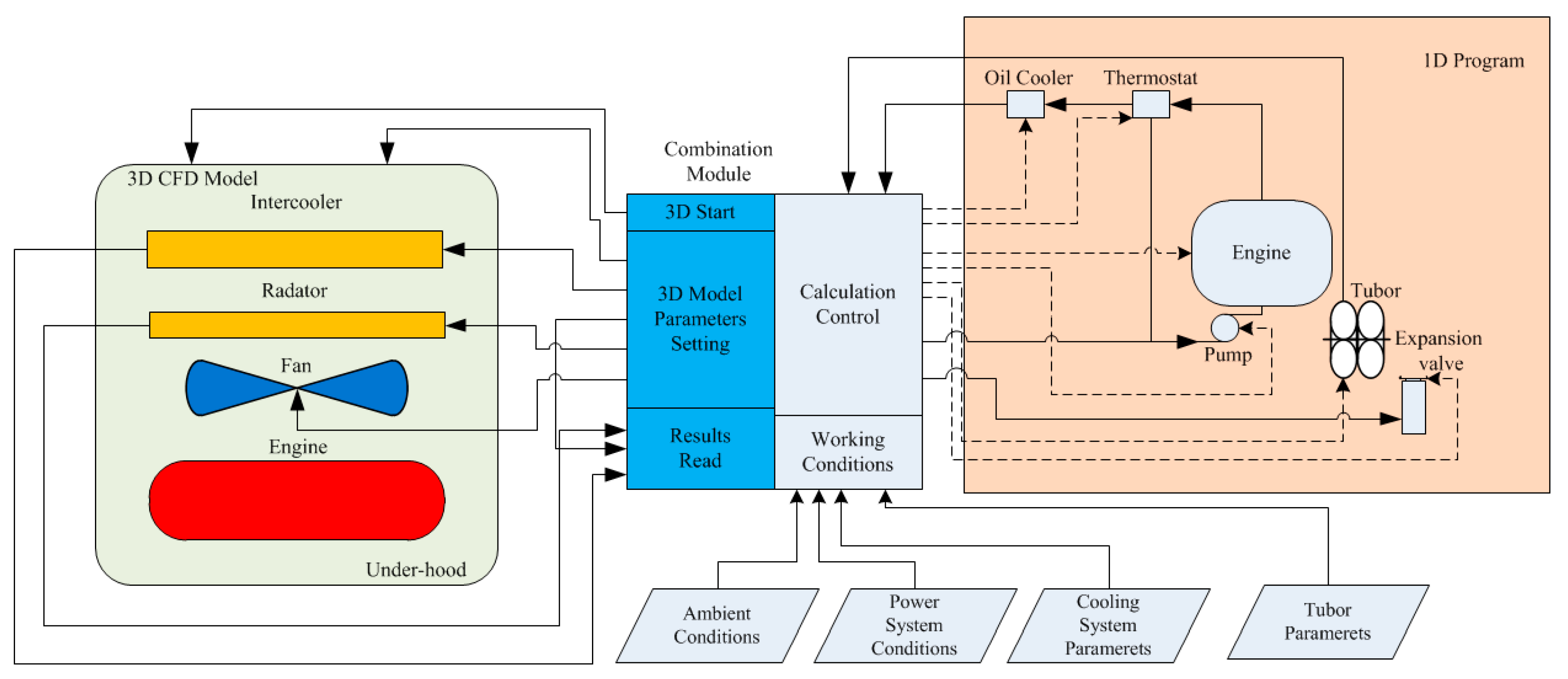
Since 2007, our research group has focused on the ICE thermal management technology and produced thermal management schemes including engine basic cooling, turbo-charged cooling and charged air inter cooling based on the co-simulation [214]. Figure 10 is the combination of a 1D and 3D scheme of ITM for ICE, produced by the authors’ research group. Through this approach, the parameters of oil cooling, engine cooling and turbo-charged cooling and charged air intercooling system can be flexibly described and optimized with the 1D program, and heat flow, the heat interaction of multiple thermodynamic systems and the velocity and temperature distribution are studied in detail with 3D CFD models.
This integrated simulation approach of under-hood thermal management realizes the integrated simulation of the 1D and 3D using the integrated control module compiled with a MATLAB routine. What’s more, it not only realizes areasonable matching and configuration optimization of cooling components in the underhood area but also provides prediction ability for underhood heat dissipation performance and high-temperature heat-harm analysis, which are identified as one of the key points in thermal management [215,216].
On the basis of current TM for ICE containing configuration matching, optimization and evaluation, the authors’ research group proposed the integration thermal management for ICE coupling with air conditioning to interpret the interactional characteristic of heat flow, cooling performance and underhood structural optimization design. Through a numerical wind tunnel simulation method, the whole vehicle aerodynamic performance and heat transfer characteristic under various ambient and driving conditions can then be assessed and analyzed [217,218]. Besides, the group has programmed software with association of the model, module and algorithm in order to implementation the 1D/3D co-simulation. With these softwares, named Multi-thermal System Analysis Software of Integration Thermal Management for Engine compartment based on Equivalent Wind Tunnel Simulation and Heat Exchanger Characteristics Performance Analysis Software the complex thermal interactions among multiple thermal components under-hood aerodynamics and heat transfer behavior with association of an air conditioning system can be analyzed and considered, which include charged air inter-cooler, oil cooler, engine cooling radiator and condenser. With the software predesign, the coupling characteristics of the thermal state and heat flow can be optimized and the synergy controlled, and this can provide the possibility for research on cabin thermal comfort and cabin airflow and temperature distribution optimization [218]. Then the steady and transient simulation and computation of vehicle dynamic performance can be achieved through this association of the numerical program and the experimental data of multiple thermal components. Figure 11 describes the advanced VITM in a synergetic process of underhood cooling and air conditioning discussed in [217], which can guarantee thermo-dynamic systems operation under optimum conditions.
3.4.2. ITM for EV
Currently, on the basis of the dynamic requirements of EPS, the team has explored electric vehicle thermal management technologies and established integrated VTM systems by liquid circulation with HP application for preheating and cooling battery packing [219,220].
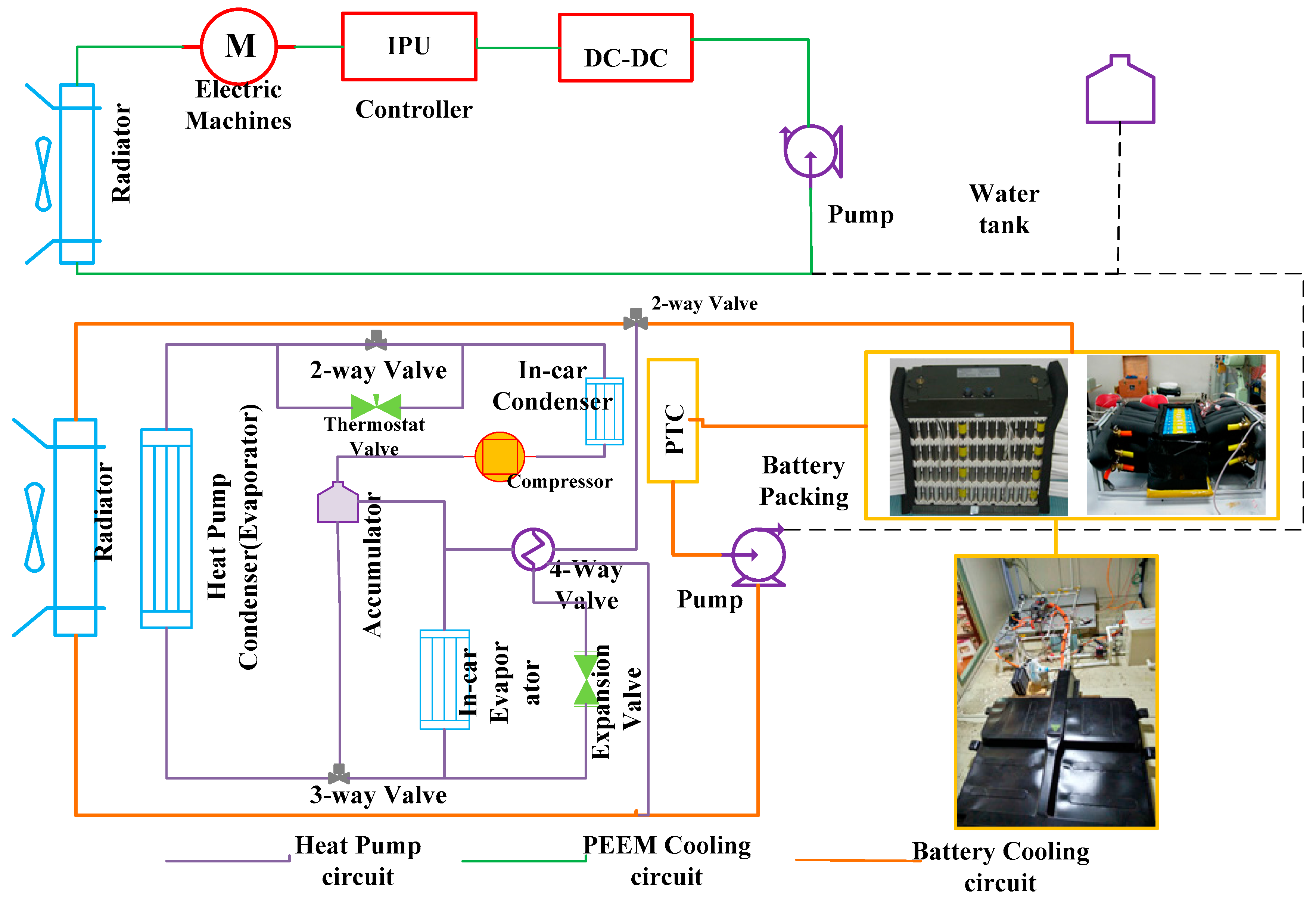
On account of the abundant research work on battery thermal management with heat pump utilization, in 2013, the team of researchers expanded a comprehensive cooperation with the founder of China’s automobile industry, FAW Group, in a strategy to build integration control and management of EPS with HP for their own brand PEV. Through computational programs and algorithm proposals, ITM design development and performance analytical estimates, an ITM framework for PEV can be established, which unites the electrical machines’ thermal management, battery packing thermal management and heat pump preheating/cooling system [221,222]. This framework is shown in Figure 12.
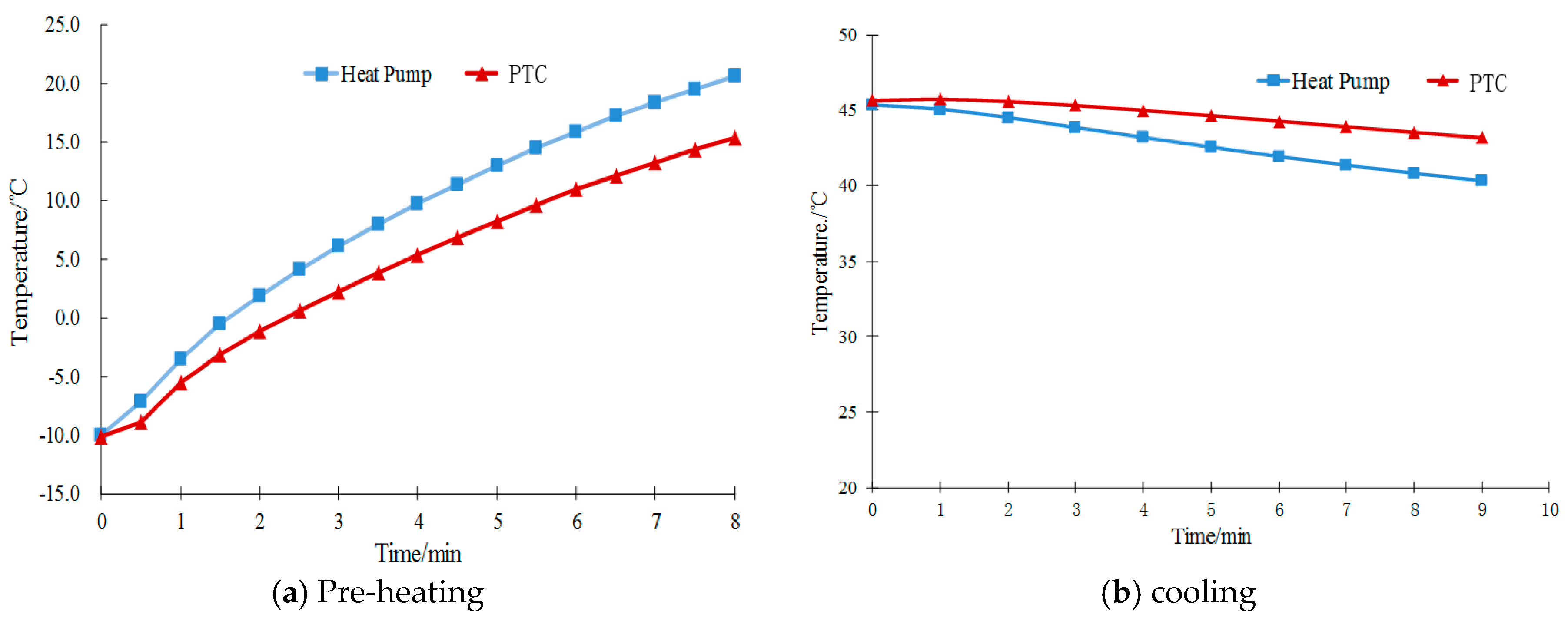
With the liquid circulation a working mechanism of electrical machines, battery packing and heat pump with interaction and combination can be achieved. Under hot ambient conditions, the heat generated from electric machines and the battery can be cooled by a heat pump through liquid circulation. In cold conditions, with the commutation function of a 4-way valve on the heat pump, the battery packing can be pre-heated in cold start-up and the passenger compartment will be warmed. This realizes the subtle climate control and active thermal management of PEV under various conditions. Besides, it can prolong the lifespan of dynamic battery packing and electric machines, as well as, improve the energy-efficiency of vehicle [222,223]. Taking the sheet battery results as an example, the data fully illustrates that, compared to the conventional Positive Temperature Coefficient (PTC) cooling/preheating method, BTM based on heat pump preheating/cooling can be a good solution for PEV and HEV cold star-up [223,224]. The data of preheating and cooling are shown in Figure 13. In the process of preheating, the average temperature of the battery with heat pump utilization, can be increased much more quickly to the appropriate temperature of 20 °C from −10 °C. In the cooling process, the average temperature of battery packing with heat pump decreases much more rapidly to the proper temperature of 40 °C from the initial 45 °C. Consequently, the liquid circulation of heat pump application can effectively shorten the response times of preheating and cooling for batteries [224,225].
4. Future Tasks and Proposals
After our review of the typical VTM application in ICEV, PEV and HEV, some strategic suggestions are proposed, so as to offer a comprehensive and powerful reference for the deeper understanding and more extensive exploration of the subject in future. Actually, to satisfy the needs of R&D of VTM, the proposal can guide the VTM innovation, development and implementation, and further facilitate vehicle energy-efficiency and conservation. The main content of future tasks and proposals are generalized as follows:
- (1)
- Exploring energy-conservation innovation in the mechanism and control strategy of vehicle AC can guarantee human bio-thermal comfort. The air supply according to variable thermal loads in transient dynamic driving process, as well as air vertical and zonal distribution pattern according to human bio-thermal comfort can save energy and reduce energy consumption.
- (2)
- Deep insight should be gained about the thermal-hydraulic interactions and characteristics, such as some thermal phenomena and behaviors, temperature gradient aberration, and heat hysteresis, among the power-dynamic systems integrated with air conditioning system both in ICEV, PEV and HEV, which are packed in a modern compact underhood. With TM of heat transfer deterioration solutions and configuration optimization of thermal-dynamic devices, the heat and mass transfer can be enhanced, and additionally, the aerodynamic and heat transfer of multi-heat sources and multi-loops within small-scale spatial structure can be precisely adjusted.
- (3)
- The synergistic and systemic control strategy for functional optimization, efficient mechanism, critical parameters of multi thermal-dynamic systems, including the stability controllability and maneuverability, should be emphasized and established via theoretical model analysis and diversified numerical simulation based on experimental validation and verification.
- (4)
- Optimizing heat transfer structural design and active thermal control and management for EPS during vehicle operation is worthy of attention, especially to improve EPS thermo-stability, based on figuring EPS action mechanism and the transient performances and response of power electrics, thermal runaway prevention including the signal detection, parametric identification principle, the diagnosis mechanism, and fire-fighting precautions should be definitely established.
- (5)
- Analysis of the mechanism of correlation and operation, and feedback principle and multi-coupling collaboration of ITM for EPS and AC, is necessary for precise thermal control to guarantee battery uniformity, shorten the transient response time in cooling/preheating processes, and optimize power dynamic performance.
The integrated thermal management of ICEV, PEV and HEV, have synergistic effects on thermal process optimizing and safety controlling. As one of vehicle core technologies, aimed at improving and promoting ITM utilization in ICEV, PEV and HEV, fundamental investigations with foresight exploration and innovation should be developed. It can be promising for the automobile manufacture and industry, further research of these mentioned solutions will strengthen theoretical understanding, and facilitate the progress, and provide powerful platform and reference for energy efficiency and conservation worldwide.
5. Conclusions
With the continuous progress in vehicle technology, ITM aimed at pursuing optimal performance and light weight has attracted widespread attention. According to the different power sources, the research objects of VITM are quite different to some extent. Regarding ICEVs, their thermal management systems contain ICE cooling, turbo-charged cooling, exhaust gas recirculation cooling, lubrication cooling and air conditioning or heat pump. As for electric vehicles, thermal management coverage mainly includes battery cooling/preheating, power electronics and electrical machines cooling and heat pump air conditioning. With the rational effective and comprehensive control over these mentioned dynamic device and thermal components, the modern vehicle TM can realize collaborative optimization of multiple thermodynamic processes in terms of system integration. Furthermore, the computer-assisted calculation and simulation has become the major design approach, especially for complex ITM systems. 1D programming can link multi-thermal components to the association, while 3D simulation can complete structuralized and modularized design, additionally, and 1D/3D co-simulation can virtualize the simulation of various thermo-hydraulic behaviors under transient vehicle operational conditions. This article reviews the advances in modern vehicle thermal management research work, which has promoted vehicle industry R&D. On the basis of the systematic summaries and combing the design method and technology application of ITM, this article presents the future tasks and proposals aimed at promoting innovation of vehicle ITM, strengthen the precise control and performance predictability and further enhance the level of R&D.
Acknowledgments
The authors gratefully acknowledge the financial fund of the National Natural Science Foundation of China (NSFC) General Program (No. 51376079). The supporting comes from the Projects of National Innovation and Development of Automobile Industry in Joint Funds of NSFC. This research is also supported by Jilin Province Government through the Science & Technology Development Plan item (No. 14KG096) and Science & Technology “Double Ten” Innovation Project.
Author Contributions
Yan Wang and Qing Gao wrote this article. Guohua Wang and Yan Wang conceived the integrated simulation approach described in Section 3.4.1; Tianshi Zhang and Yan Wang were responsible for the work mentioned in Section 3.4.2, Yan Wang performed the experiment and analyzed the data shown in Section 3.4.2; Zhipeng Jiang and Yunxia Li contributed analysis tools.
Conflicts of Interest
The authors declare no conflict of interest.
References
- Tie, S.F.; Tan, C.W. A review of energy sources and energy management system in electric vehicles. Renew. Sustain. Energy Rev. 2013, 20, 82–102. [Google Scholar] [CrossRef]
- Zhang, P.; Yan, F.; Du, C. A comprehensive analysis of energy management strategies for hybrid electric vehicles based on bibliometrics. Renew. Sustain. Energy Rev. 2015, 48, 88–104. [Google Scholar] [CrossRef]
- Banjac, T.; Wurzenberger, J.C.; Katrašnik, T. Assessment of engine thermal management through advanced system engineering modeling. Adv. Eng. Softw. 2014, 71, 19–33. [Google Scholar] [CrossRef]
- Kumar, V.; Shendge, S.A.; Baskar, S. Underhood Thermal Simulation of a Small Passenger Vehicle with Rear Engine Compartment to Evaluate and Enhance Radiator Performance; SAE Technical Paper 2010-01-0801; SAE International: Washington, DC, USA, 2010. [Google Scholar]
- Wambsganss, M.W. Tube vibration and flow distribution in shell-and-tube heat exchangers. Heat Transf. Eng. 1987, 8, 62–72. [Google Scholar] [CrossRef]
- Croitoru, C.; Nastase, I.; Bode, F.; Meslem, A.; Dogeanu, A. Thermal comfort models for indoor spaces and vehicles—Current capabilities and future perspectives. Renew. Sustain. Energy Rev. 2015, 44, 304–318. [Google Scholar] [CrossRef] [Green Version]
- Page, R.W.; Hnatczuk, W. Thermal Management for the 21st Century—Improved Thermal Control & Fuel Economy in an Army Medium Tactical Vehicle; SAE Technical Paper 2005-01-2068; SAE International: Washington, DC, USA, 2005. [Google Scholar]
- Mahmoud, K.G.; Loibner, E.; Wiesler, B.; Samhaber, C.; Kußmann, Ch. Simulation-Based Vehicle Thermal Management System—Concept and Methodology. In Proceedings of the 2003 SAE World Congress, Detroit, MI, USA, 3–6 March 2003. [Google Scholar]
- Gering, K.L.; Haefner, D.R. Methods of Forming Thermal Management Systems and Thermal Management Methods. U.S. Patent 8,191,618, 5 June 2012. [Google Scholar]
- Allen, D.A.; Lasecki, M.P. Thermal management evolution and controlled coolant flow. In Proceedings of the Vehicle Thermal Management Systems Conference and Exhibition, Nashville, TN, USA, 14–17 May 2001. [Google Scholar]
- Leslie, S.W. Charles F. Kettering and the copper-cooled engine. Technol. Cult. 1979, 20, 752–776. [Google Scholar] [CrossRef]
- Briggs, I.; Murtagh, M.; Kee, R.; McCulloug, G.; Douglas, R. Sustainable non-automotive vehicles: The simulation challenges. Renew. Sustain. Energy Rev. 2017, 68, 840–851. [Google Scholar] [CrossRef]
- Han, T.; Chen, K.; Khalighi, B.; Curran, A.; Pryor, J.; Hepokoski, M. Assessment of various environmental thermal loads on passenger thermal comfort. SAE Int. J. Passeng. Cars Mech. Syst. 2010, 3, 830–841. [Google Scholar] [CrossRef]
- Zucchetto, J.; Myers, P.; Johnson, J.; Miller, D. An assessment of the performance and requirements for “adiabatic” engines. Science 1988, 240, 1157–1162. [Google Scholar] [CrossRef] [PubMed]
- Dutta, N.; Rouaud, C.; Masera, M.; Beuzelin, F.; Hughes, C.A.V. Powertrain cooling concept selection process for hybrid electric vehicles. In Innovations in Fuel Economy and Sustainable Road Transport; Elsevier Science: Burlington, NJ, USA, 2011; pp. 61–72. [Google Scholar]
- Rugh, J.P.; Bennion, K.; Brooker, A.; Langewisch, J.; Smith, K.; Meyer, J. PHEV/EV integrated vehicle thermal management—Development of a KULI model to assess combined cooling loops. In Vehicle Thermal Management Systems Conference and Exhibition (VTMS10); Elsevier Science: Burlington, NJ, USA, 2011; pp. 649–660. [Google Scholar]
- Marquis-Favre, W.; Bideaux, E.; Scavarda, S. A planar mechanical library in the AMESim simulation software. Part I: Formulation of dynamics equations. Simul. Model. Pract. Theory 2006, 14, 25–46. [Google Scholar] [CrossRef]
- Marquis-Favre, W.; Bideaux, E.; Scavarda, S. A planar mechanical library in the AMESim simulation software. Part II: Library composition and illustrative example. Simul. Model. Pract. Theory 2006, 14, 95–111. [Google Scholar] [CrossRef]
- Bennion, K.; Thornton, M. Integrated Vehicle Thermal Management for Advanced Vehicle Propulsion Technologies; SAE Paper 2010-01-0836; National Renewable Energy Laboratory (NREL): Golden, CO, USA, 2010.
- Schweiger, C.; Dempsey, M.; Otter, M. The PowerTrain Library: New Concepts and New Fields of Application. In Proceedings of the 4th International Modelica Conference, Hamburg, Germany, 7–8 March 2005; pp. 457–466. [Google Scholar]
- Yokoyama, A.; Osaka, T.; Imanishi, Y.; Sekiya, S. Thermal Management System for Electric Vehicles. SAE Int. J. Mater. Manuf. 2011, 4, 1277–1285. [Google Scholar] [CrossRef]
- Zhuang, X.; Jiang, K. A Study on the Roadmap of Electric Vehicle Development in China. Autom. Eng. 2012, 34, 91–97. [Google Scholar]
- Jung, D.; Yong, J.; Choi, H.; Song, H.; Min, K. Analysis of engine temperature and energy flow in diesel engine using engine thermal management. J. Mech. Sci. Technol. 2013, 27, 583–592. [Google Scholar] [CrossRef]
- Emmenthal, K.D.; Hucho, W.-H. A Rational Approach to Automotive Radiator Systems Design. In Proceedings of the Automotive Engineering Congress, Detroit, MI, USA, 25 February–1 March 1974. [Google Scholar]
- Priede, T.; Anderton, D. Likely Advances in Mechanics, Cooling, Vibration and Noise of Automotive Engines. Proc. Inst. Mech. Eng. Part D Transp. Eng. 1984, 198, 95–106. [Google Scholar] [CrossRef]
- Finlay, I.C.; Harris, D.; Boam, D.J.; Parks, B.I. Factors influencing Combustion Chamber Wall Temperatures in a Liquid Cooled, Automotive Spark Ignition Engine. Proc. Inst. Mech. Eng. Part D Transp. Eng. 1985, 199, 207–214. [Google Scholar] [CrossRef]
- Finlay, C.; Gallacher, G.R.; Biddulph, T.W.; Marshall, R.A. The Application of Precision Cooling to the Cylinder Head of a Small Automotive Petrol Engine. In Proceedings of the International Congress and Exposition, Detroit, MI, USA, 29 February–4 March 1988. [Google Scholar]
- Kling, E.R. Truck Cooling System Airflow; SAE Technical Paper 580089; SAE International: Washington, DC, USA, 1958. [Google Scholar]
- Damodaran, V.; Rahman, M. Front-End Cooling Airflow Performance Prediction Using Vehicle System Resistance; SAE Technical Paper 2003-01-0273; SAE International: Washington, DC, USA, 2003. [Google Scholar]
- Caresana, F.; Bilancia, M.; Bartolini, C.M. Numerical method for assessing the potential of smart engine thermal management: Application to a medium-upper segment passenger car. Appl. Therm. Eng. 2011, 31, 3559–3568. [Google Scholar] [CrossRef]
- Andrew, A.; Kenny, C.F.B.; Cree, B.T. Electronic Thermostat System for a Automotive Engine. In Proceedings of the International Congress and Exposition, Detroit, MI, USA, 29 February–4 March 1988. [Google Scholar]
- Zou, X.; Jordan, J.A.; Shillor, M. A dynamic model search for a thermostat. J. Eng. Math. 1999, 36, 291–310. [Google Scholar] [CrossRef]
- Cortona, E. Active coolant control strategies in automotive engines. Int. J. Autom. Technol. 2010, 6, 767–772. [Google Scholar]
- Robinson, K.; Campbell, N.A.F.; Hawley, J.G.; Tilley, D.G. A Review of Precision Engine Cooling. In Proceedings of the International Congress and Exposition, Detroit, MI, USA, 1–4 March 1999. [Google Scholar]
- Perset, D.; Jouannet, B. Simulation of a Cooling Loop for a Variable Speed Fan System. In Proceedings of the International Congress and Exposition, Detroit, MI, USA, 1–4 March 1999. [Google Scholar]
- Chanfreau, M.; Gessier, B.; Farkh, A.; Geels, P.Y. The need for an Electrical Water Valve in a Thermal Management Intelligent System (THEMIS™). In Proceedings of the 2003 SAE World Congress, Detroit, MI, USA, 3–6 March 2003. [Google Scholar]
- Chanfreau, M.; Joseph, A.; Butler, D.; Richard, S. Advanced Engine Cooling Thermal Management System on a Dual Voltage 42V-14V Minivan. In Proceedings of the Vehicle Thermal Management Systems Conference & Exposition, Nashville, TN, USA, 22–25 May 2001. [Google Scholar]
- Ap, N.; Tarquis, M. Innovative Engine Cooling Systems Comparison. In Proceedings of the SAE 2005 World Congress and Exhibition, Detroit, MI, USA, 11–14 April 2005. [Google Scholar]
- Wagner, J.; Paradis, I.; Marotta, E.; Dawson, D. Enhanced Automotive Engine Cooling System: A Mechatronics Approach (OCR). Int. J. Veh. Des. 2002, 28, 214–240. [Google Scholar] [CrossRef]
- Ribeiro, E.G.; de Carvalho Meira, J.L.; de Andrade Filho, A.P. Electric valve for coolant temperature control (TCV). In Proceedings of the SAE Brasil 2007 Congress and Exhibit, Sao Paulo, Brazil, 22–24 November 2007. [Google Scholar]
- Cho, H.; Jung, D.; Filipi, Z.S.; Assanis, D.N.; Vanderslice, J. Application of Controllable Electric Coolant Pump for Fuel Economy And Cooling Performance Improvement. J. Eng. Gas Turbines Power 2007, 129, 43–50. [Google Scholar] [CrossRef]
- Wang, T.; Wagner, J. Advanced automotive thermal management—Nonlinear radiator fan matrix control. Control Eng. Pract. 2015, 41, 113–123. [Google Scholar] [CrossRef]
- Mitchell, T.; Salah, M.; Wagner, J.; Dawson, D. Automotive Thermostat Valve Configurations: Enhanced Warm-up Performance. J. Dyn. Syst. Meas. Control 2009, 131, 442–447. [Google Scholar] [CrossRef]
- Melzer, F.; Hesse, U.; Pocklage, G.; Schimitt, M. Thermomanagment. In Proceedings of the International Congress & Exposition, Detroit, MI, USA, 1–4 March 1999. [Google Scholar]
- Kern, J.; Amros, P. Concepts for a Controlled optimized Vehicle Engine Cooling system. In Proceedings of the 1995 Vehicle Thermal Management Systems Conference and Exhibition, Washington, DC, USA, 13–17 May 1995. [Google Scholar]
- Juan, T. Investigation and Assessment of Factors Affecting the Underhood Cooling Air Flow Using CFD. In Proceedings of the Commercial Vehicle Engineering Congress & Exhibition, Rosemont, IL, USA, 30 October 2007. [Google Scholar]
- Burke, R.D.; Brace, C.J.; Hawley, J.G.; Pegg, I. Review of the systems analysis of interactions between the thermal, lubricant, and combustion processes of diesel engines. Proc. Inst. Mech. Eng. Part D J. Autom. Eng. 2010, 224, 681–704. [Google Scholar] [CrossRef]
- Leising, C.J.; Purohit, G.P.; DeGrey, S.P.; Finegold, J.G. Waste heat recovery in truck engines. In Proceedings of the National West Coast Meeting, San Diego, CA, USA, 7–10 August 1978. [Google Scholar]
- Zheng, M.; Reader, G.T.; Hawley, J.G. Diesel engine exhaust gas recirculation a review on advanced and novel concepts. Energy Convers. Manag. 2004, 45, 883–900. [Google Scholar] [CrossRef]
- Doyle, E.; DiNanno, L.; Kramer, S. Installation of a diesel organic rankine compound engine in a class-8 truck for a single vehicle test. In Proceedings of the Passenger Car Meeting & Exposition, Dearborn, MI, USA, 11–15 June 1979. [Google Scholar]
- Patel, P.S.; Doyle, E.F. Compounding the truck diesel engine with an organic Rankine-cycle system. In Proceedings of the 1976 Automotive Engineering Congress and Exposition, Detroit, MI, USA, 24–27 February 1976. [Google Scholar]
- Yu, C.; Wang, J.X.; Wang, Z.; Shuai, S.J. Comparative study on gasoline homogeneous charge induced ignition (HCII) by diesel and gasoline/diesel blend fuels (GDBF) combustion. Fuel 2013, 106, 470–477. [Google Scholar] [CrossRef]
- Liu, L.; Ling, X.; Peng, H. Complex turbulent flow and heat transfer characteristics of tubes with internal longitudinal plate-rectangle fins in EGR cooler. Appl. Therm. Eng. 2013, 54, 145–152. [Google Scholar] [CrossRef]
- Yao, M.; Zheng, Z.; Liu, H. Progress and recent trends in homogeneous charge compression ignition (HCCI) engines. Prog. Energy Combust. Sci. 2009, 35, 398–437. [Google Scholar] [CrossRef]
- Liu, L.; Ling, X.; Peng, H. Analysis on flow and heat transfer characteristics of EGR helical baffled cooler with spiral corrugated tubes. Exp. Therm. Fluid Sci. 2013, 44, 275–284. [Google Scholar] [CrossRef]
- Sato, A.; Suenaga, K.; Noda, M.; Maeda, Y. Advanced Boost-up in Hino EP100-II Turbocharged and Charge-Cooled Diesel Engine. In Proceedings of the SAE International Congress and Exposition, Detroit, MI, USA, 23–27 February 1987. [Google Scholar]
- Mirajkar, N.S.; Adhikarath Tharayi, R. Thermal Management in Engine Compartment for Efficient Working of the Intercooler on a Rear Engine Vehicle. In Proceedings of the SAE 2012 World Congress & Exhibition, Detroit, MI, USA, 24–26 April 2012. [Google Scholar]
- Taitt, D.W.; Garner, C.P.; Swain, E.; Bassett, M.D.; Pearson, R.J. An automotive engine charge-air conditioner system: Thermodynamic analysis of performance characteristics. Proc. Inst. Mech. Eng. Part D J. Autom. Eng. 2005, 219, 389–404. [Google Scholar] [CrossRef] [Green Version]
- Burgold, S.; Galland, J.P.; Ferlay, B.; Odillard, L. Modular Water Charge Air Cooling for Combustion Engines. MTZ Worldw. 2012, 73, 26–31. [Google Scholar] [CrossRef]
- Chalgren, R.D.; Parker, G.; Arici, O.; Johnson, J. A Controlled EGR Cooling System for Heavy Duty Diesel Applications Using the Vehicle Engine Cooling System Simulation. In Proceedings of the SAE 2002 World Congress & Exhibition, Detroit, MI, USA, 4–7 March 2002. [Google Scholar]
- Luptowski, B.J.; Arici, O.; Johnson, H.J.; Parker, G.G. Development of the Enhanced Vehicle and Engine Cooling System Simulation and application to Active Cooling Control. In Proceedings of the SAE 2005 World Congress & Exhibition, Detroit, MI, USA, 11–14 April 2005. [Google Scholar]
- Lienhart, F.; Boussen, S.; Carraz, O.; Zahzam, N.; Bidel, Y.; Bresson, A. Compact and robust laser system for rubidium laser cooling based on the frequency doubling of a fiber bench at 1560 nm. Appl. Phys. B 2007, 89, 177–180. [Google Scholar] [CrossRef]
- Rotter, T.M.; Van Dyke, V. Oil Cooling Device. U.S. Patent US5351664, 4 October 1994. [Google Scholar]
- Djamali, M.; Tenbohlen, S. Malfunction Detection of the Cooling System in Air-Forced Power Transformers Using Online Thermal Monitoring. IEEE Trans. Power Deliv. 2017, 32, 1058–1067. [Google Scholar] [CrossRef]
- Dong, H.L.; Kim, S.C. Thermal performance of oil spray cooling system for in-wheel motor in electric vehicles. Appl. Therm. Eng. 2014, 63, 577–587. [Google Scholar]
- Teng, H. Improving fuel economy for HD diesel engines with WHR Rankine cycle driven by EGR cooler heat rejection. In Proceedings of the SAE 2009 Commercial Vehicle Engineering Congress & Exhibition, Rosemont, IL, USA, 7 October 2009. [Google Scholar]
- Saab, S. Combined Modeling of Thermal Systems of an Engine in the Purpose of a Reduction in the Fuel Consumption. In Proceedings of the 11th International Conference on Engines & Vehicles, Napoli, Italy, 15–19 September 2013. [Google Scholar]
- Hountalas, D.T.; Georgios, C. Improvement of bottoming cycle efficiency and heat rejection for HD truck applications by utilization of EGR and CAC heat. Energy Convers. Manag. 2012, 53, 19–32. [Google Scholar] [CrossRef]
- Ringler, J.; Seifert, M.; Guyotot, V.; Huebner, W. Rankine cycle for waste heat recovery of IC engines. In Proceedings of the SAE 2009 World Congress & Exhibition, Detroit, MI, USA, 20–23 April 2009. [Google Scholar]
- Ap, N.; Jouanny, P.; Potier, M.; Genoist, J. UltimateCooling™ System for New Generation of Vehicle. In Proceedings of the Vehicle Thermal Management Systems Conference & Exposition, Nashville, TN, USA, 22–25 May 2005. [Google Scholar]
- Ap, N.S.; Guerrero, P.; Jouanny, P.; Potier, M.; Genoist, J.; Thuez, J.L. Ultimate Cooling™—New concept cooling system concept using the same coolant to cool all vehicle fluids. In Proceedings of the 2003 Vehicle Thermal Management Systems Conference (VTMS6), Brighton, UK, 18–21 May 2003. C599/010/2003 IMechE2003. [Google Scholar]
- Kim, Y.; Song, Y. High/Low Temperature Water Cooling System. U.S. Patent No. US20040050543 A1, 18 March 2004. [Google Scholar]
- Cipollone, R.; Di Battista, D. Performances and Opportunities of an Engine Cooling System with a Double Circuit at Two Temperature Levels. In Proceedings of the SAE 2012 World Congress & Exhibition, Detroit, MI, USA, 24–26 April 2012. [Google Scholar]
- Zhang, B.; Xiong, R.; Wu, J. Research of Automotive Compact Cooling System. Small Intern. Combust. Engine Motorcycle 2013, 42, 42–47. [Google Scholar]
- Soldner, J.; Zobel, W.; Ehlers, M.; Nies, J.; Wattelet, J. A Compact Cooling System (CCSTM): The Key to Meet Future Demands in Heavy Truck Cooling. In Proceedings of the Vehicle Thermal Management Systems Conference & Exposition, Nashville, TN, USA, 22–25 May 2001. [Google Scholar]
- Yang, Z.; Bozeman, J.; Shen, F.Z.; Turner, D.; Vemuri, S.; Acre, J.A. CFRM Concept for Vehicle Thermal System. In Proceedings of the SAE 2002 World Congress & Exhibition, Detroit, MI, USA, 4–7 March 2002. [Google Scholar]
- Chalgren, R.D.; Allen, D.J. Light Duty Diesel Advanced Thermal Management. In Proceedings of the Vehicle Thermal Management Systems Conference & Exposition, Nashville, TN, USA, 22–25 May 2005. [Google Scholar]
- Mathur, G.D. Development of an Innovative Energy Efficient Compact Cooling System “SLIM”. In Proceedings of the SAE 2012 World Congress & Exhibition, Detroit, MI, USA, 24–26 April 2012. [Google Scholar]
- Wang, T.; Wagner, J. Advanced Engine Cooling System Subjected to Ram Air Effect? Nonlinear Adaptive Multiple Input and Multiple Output (NAMIMO) Control. IEEE Trans. Veh. Technol. 2017, 66, 7730–7740. [Google Scholar] [CrossRef]
- Gonzales, B.; Chopard, G.; Charry, B.; Berger, E.; Tripard, J.; Magnin, E.; Groslambert, A. Effects of a Training Program Involving Body Cooling on Physical and Cognitive Capacities and Quality of Life in Multiple Sclerosis Patients: A Pilot Study. Eur. Neurol 2017, 78, 71–77. [Google Scholar] [CrossRef] [PubMed]
- Sakurai, Y.; Kadoi, H.; Nakada, T.; Edamura, K. Development of Printed Circuit Board Multi-layered Type ECF-pump and Its Application to Liquid Cooling System. Trans. Jpn. Soc. Mech. Eng. C 2006, 72, 991–996. [Google Scholar] [CrossRef]
- Mains, R.T. Multiple Passage Cooling Circuit Method and Device for Gas Turbine Engine Fuel Nozzle. U.S. Patent US5423178 A, 13 June 1995. [Google Scholar]
- Song, X.; Myers, J.; Sarnia, S. Integrated Low Temperature Cooling System Development in Turbo Charged Vehicle Application. SAE Int. J. Passeng. Cars Mech. Syst. 2014, 7, 163–173. [Google Scholar] [CrossRef]
- Jossen, V.; Spath, V.; Doring, H.; Garche, J. Reliable battery operation—A challenge for the battery management system. J. Power Sources 1999, 84, 283–286. [Google Scholar] [CrossRef]
- Williford, R.E.; Viswanathan, V.V.; Zhang, J.G. Effects of entropy changes in anodes and cathodes on the thermal behavior of lithium-ion batteries. J. Power Sources 2009, 189, 101–107. [Google Scholar] [CrossRef]
- Teng, H.; Ma, Y.; Yeow, K.; Thelliez, M. An analysis of a lithium-ion battery system with indirect air cooling and warm-up. SAE Int. J. Passeng. Cars Mech. Syst. 2011, 4, 1343–1357. [Google Scholar] [CrossRef]
- Wang, Q.; Jiang, B.; Li, B.; Yan, Y. A critical review of thermal management models and solutions of lithium-ion batteries for the development of pure electric vehicles. Renew. Sustain. Energy Rev. 2016, 64, 106–128. [Google Scholar] [CrossRef]
- Ling, Z.; Zhang, Z.; Shi, G.; Fang, X.; Wang, L.; Gao, X.; Fang, Y.; Xu, T.; Wang, S.; Liu, X. Review on thermal management systems using phase change materials for electronic components, Li-ion batteries and photovoltaic modules. Renew. Sustain. Energy Rev. 2014, 31, 427–438. [Google Scholar] [CrossRef]
- Kizilel, R.; Sabbah, R.; Selman, J.R.; Al-Hallaj, S. An alternative cooling system to enhance the safety of Li-ion battery packs. J. Power Sources 2009, 194, 1105–1112. [Google Scholar] [CrossRef]
- Rao, Z.H.; Wang, S.F.; Wu, M.C.; Lin, Z.R.; Li, F.H. Experimental investigation on thermal management of electric vehicle battery with heat pipe. Energy Convers. Manag. 2013, 65, 92–97. [Google Scholar] [CrossRef]
- Zou, H.; Wang, W.; Zhang, G.; Qin, F.; Tian, C.; Yan, Y. Experimental investigation on an integrated thermal management system with heat pipe heat exchanger for electric vehicle. Energy Convers. Manag. 2016, 118, 88–95. [Google Scholar] [CrossRef]
- Hémery, C.V.; Pra, F.; Robin, J.F. Experimental performances of a battery thermal management system using a phase change material. J. Power Sources 2014, 270, 349–358. [Google Scholar] [CrossRef]
- Chen, D.; Jiang, J.; Kim, G.-H.; Yang, C.; Pesaran, A. Comparison of different cooling methods for lithium ion battery cells. Appl. Therm. Eng. 2016, 94, 846–854. [Google Scholar] [CrossRef]
- Sabbah, R.; Kizilel, R.; Selman, J.R.; Al-Hallaj, S. Active (air-cooled) vs. passive (phase change material) thermal management of high power lithium-ion packs: Limitation of temperature rise and uniformity of temperature distribution. J. Power Sources 2008, 182, 630–638. [Google Scholar] [CrossRef]
- Rao, Z.; Wang, S. A review of power battery thermal energy management. Renew. Sustain. Energy Rev. 2011, 15, 4554–4571. [Google Scholar] [CrossRef]
- Zolot, M.D.; Kelly, K.; Keyser, M.; Mihalic, M.; Pesaran, A.; Hieronymus, A. Thermal evaluation of the Honda Insight battery pack. In Proceedings of the 36th Energy Conversion Engineering Conference, Savannah, Georgia, 29 July–2 August 2001; Volume 2, pp. 923–928. [Google Scholar]
- Zolot, M.; Pesaran, A.A.; Mihalic, M. Thermal evaluation of Toyota Prius battery pack. In Proceedings of the SAE Future Car Congress, Arlington, VA, USA, 3–5 June 2002. [Google Scholar]
- Al-Hallaj, S.; Selman, J.R. Thermal Management of Battery Systems. U.S. Patent 6,468,689 B1, 22 October 2002. [Google Scholar]
- Khateeb, S.A.; Farid, M.M.; Selman, J.R.; Al-Hallaj, S. Design and simulation of a lithium-ion battery with a phase change material thermal management system for an electric scooter. J. Power Sources 2004, 128, 292–307. [Google Scholar] [CrossRef]
- Wu, M.S.; Liu, K.H.; Wang, Y.Y.; Wan, C.C. Heat dissipation design for lithium-ion batteries. J. Power Sources 2002, 109, 160–166. [Google Scholar] [CrossRef]
- Jang, J.C.; Rhi, S.H. Battery thermal management system of future electric vehicles with loop thermosyphon. In Proceedings of the US-Korea Conference on Science, Technology, and Entrepreneurship (UKC), Bellevue, WA, USA, 11–15 August 2010. [Google Scholar]
- Park, Y.J.; Jun, S.; Kim, S.; Lee, D.-H. Design optimization of a loop heat pipe to cool a lithium ion battery onboard a military aircraft. J. Mech. Sci. Technol. 2010, 24, 609–618. [Google Scholar] [CrossRef]
- Li, Y.; He, J.; He, H.; Yan, Y.; Zeng, Z.; Li, B. Investigation of ultra-thin flattened heat pipes with sintered wick structure. Appl. Therm. Eng. 2015, 86, 106–118. [Google Scholar] [CrossRef]
- Yuan, H.; Wang, L.; Wang, L. Battery Thermal Management System with Liquid Cooling and Heating in Electric Vehicles. Autom. Saf. Energy 2012, 3, 371–380. [Google Scholar]
- Elwert, T.; Goldmann, D.; Römer, F.; Buchert, M.; Merz, C. Current Developments and Challenges in the Recycling of Key Components of (Hybrid) Electric Vehicles. Recycling 2015, 1, 25–60. [Google Scholar] [CrossRef]
- Chen, Y.; Evans, J.W. Heat transfer phenomena in lithium/polymer-electrolyte batteries for electric vehicle application. J. Electrochem. Soc. 1993, 140, 1833–1838. [Google Scholar] [CrossRef]
- Kim, N.; Moawad, A.; Shidore, N.; Rousseau, A. Fuel Consumption and Cost Potential of Different Plug-In Hybrid Vehicle Architectures. SAE Int. J. Altern. Powertrains 2015, 4, 88–99. [Google Scholar] [CrossRef]
- Pendergast, D.R.; DeMauro, E.P.; Fletcher, M.; Stimson, E.; Mollendorf, J.C. A rechargeable lithium-ion battery module for underwater use. J. Power Sources 2011, 196, 793–800. [Google Scholar] [CrossRef]
- Chacko, S.; Charmer, S. Lithium-ion pack thermal modeling and evaluation of indirect liquid cooling for electric vehicle battery thermal management. In Innovations in Fuel Economy and Sustainable Road Transport; Woodhead Publishing: Cambridge, UK, 2011; pp. 13–21. [Google Scholar]
- Jarrett, A.; Yong, K. Design optimization of electric vehicle battery cooling plates for thermal performance. J. Power Sources 2011, 196, 10359–10368. [Google Scholar] [CrossRef]
- Singh, R.R.; Chelliah, T.R.; Agarwal, P. Power electronics in hydro electric energy systems—A review. Renew. Sustain. Energy Rev. 2014, 32, 944–959. [Google Scholar] [CrossRef]
- Ulbrich, S.; Kopte, J.; Proske, J. Cooling fin optimization on a TEFC electrical machine housing using a 2D conjugate heat transfer model. IEEE Trans. Ind. Electron. 2017, PP, 1. [Google Scholar] [CrossRef]
- Tüysüz, A.; Meyer, F.; Steichen, M. Advanced Cooling Methods for High-Speed Electrical Machines. IEEE Trans. Ind. Appl. 2017, 53, 2077–2087. [Google Scholar]
- Ye, Z.; Luo, W. Simulative Analysis of Traction Motor Cooling System Base on CFD. In Proceedings of the International Conference on Electric Information and Control Engineering, Wuhan, China, 15–17 April 2011; pp. 746–749. [Google Scholar]
- PALindh, P.M.; Petrov, I.; Semken, R.S.; Niemelä, M.; Pyrhönen, J.J. Direct Liquid Cooling in Low-Power Electrical Machines: Proof-of-Concept. IEEE Trans. Energy Convers. 2016, 31, 1257–1266. [Google Scholar]
- Moradnia, P.; Chernoray, V.; Nilsson, H. Experimental assessment of a fully predictive CFD approach, for flow of cooling air in an electric generator. Appl. Energy 2014, 124, 223–230. [Google Scholar] [CrossRef]
- Lee, Y.; Hahn, S.; Kauh, S.K. Thermal analysis of induction motor with forced cooling channels. IEEE Trans. Magn. 2000, 36, 1398–1402. [Google Scholar]
- Nakahama, T. Cooling Airflow in Unidirectional Ventilated Open-Type Motor for Electric Vehicles. IEEE Trans. Energy Convers. 2006, 21, 645–651. [Google Scholar] [CrossRef]
- Kimotho, J.K.; Hwang, P. Thermal Management of Electric Vehicle BLDC Motor. In Proceedings of the 16th Asia Pacific Automotive Engineering Conference, Chennai, India, 6–8 October 2011. [Google Scholar]
- Larraona, G.S.; Rivas, A.; Antón, R.; Ramos, J.C.; Pastor, I.; Moshfegh, B. Computational parametric study of an impinging jet in a cross-flow configuration for electronics cooling applications. Appl. Therm. Eng. 2013, 52, 428–438. [Google Scholar] [CrossRef]
- Park, H. A microchannel heat exchanger design for microelectronics cooling correlating the heat transfer rate in terms of Brinkman number. Microsyst. Technol. 2009, 15, 1373–1378. [Google Scholar] [CrossRef]
- Liu, Z. Direct Coil Cooling of a High Performance Switched Reluctance Machine (SRM) for EV/HEV Applications. In Proceedings of the SAE 2015 World Congress & Exhibition, Detroit, MI, USA, 21–23 April 2015. [Google Scholar]
- Zheng, P.; Liu, R. Research on the Cooling System of a 4QT Prototype Machine Used for HEV. IEEE Trans. Energy Convers. 2008, 23, 61–67. [Google Scholar] [CrossRef]
- Park, H. Numerical assessment of liquid cooling system for power electronics in fuel cell electric vehicles. Int. J. Heat Mass Transf. 2014, 73, 511–520. [Google Scholar] [CrossRef]
- Qi, Z. Advances on air conditioning and heat pump system in electric vehicles—A review. Renew. Sustain. Energy Rev. 2014, 38, 754–764. [Google Scholar] [CrossRef]
- Meyer, J.; Yang, G.; Papoulis, E. R134a heat pump for improved passenger comfort. In Proceedings of the SAE 2004 World Congress & Exhibition, Detroit, MI, USA, 1–5 March 2004. [Google Scholar]
- Steiner, A.; Rieberer, R. Parametric analysis of the defrosting process of a reversible heat pump system for electric vehicles. Appl. Therm. Eng. 2013, 61, 393–400. [Google Scholar] [CrossRef]
- Cardol, O.; Lebrun, J.; Winandy, E.; Petitjean, C. Characterization and modelling of a Hermetic scroll compressor for automotive air conditioning. In Proceedings of the International Conference on Compressors and Their Systems, London, UK, 9–12 September 2001. [Google Scholar]
- Kowsky, C.; Wolfe, E.; Leitzel, L.; Oddi, F. Unitary HPAC system. SAE Int. J. Passeng. Cars Mech. Syst. 2012, 5, 1016–1025. [Google Scholar] [CrossRef]
- Rahman, K.M.; Jurkovic, S.; Stancu, C.; Morgante, J. Design and performance of electrical propulsion system of extended range electric vehicle (EREV) Chevrolet volt. IEEE Trans. Ind. Appl. 2015, 51, 2479–2488. [Google Scholar] [CrossRef]
- Nemesh, M.D.; Stanke, E.J.; Martinchick, M.J.; Ibri, W.; Singh, K.W. HVAC and Battery Thermal Management for a Vehicle. U.S. Patent US20090249807 A1, 8 October 2009. [Google Scholar]
- National Renewable Energy Laboratory. NREL Reveals Links among Climate Control, Battery Life, and Electric Vehicle Range (Fact Sheet); Office of Scientific & Technical Information Technical Reports; National Renewable Energy Laboratory (NREL): Golden, CO, USA, 2012.
- Rugh, J.P. Integrated Vehicle Thermal Management—Combining Fluid Loops on Electric Drive Vehicles. In Vehicle and Systems Simulation and Testing 2012 Annual Progress Report; National Renewable Energy Laboratory (NREL): Golden, CO, USA, 2013; pp. 156–164. [Google Scholar]
- Leighton, D. Combined Fluid Loop Thermal Management for Electric Drive Vehicle Range Improvement. SAE Int. J. Passeng. Cars Mech. Syst. 2015, 8, 711–720. [Google Scholar] [CrossRef]
- APATrancho, E.; Ibarra, E.; Arias, A.; Kortabarria, I.; Jurrgens, J.; Marengo, L. PM-Assisted Synchronous Reluctance Machine Flux Weakening Control for EV and HEV Applications. IEEE Trans. Ind. Electron. 2017, PP, 1. [Google Scholar] [CrossRef]
- Shahverdi, M.; Mazzola, M.S.; Grice, Q.; Doude, M. Bandwidth-Based Control Strategy for a Series HEV with Light Energy Storage System. IEEE Trans. Veh. Technol. 2017, 66, 1040–1052. [Google Scholar] [CrossRef]
- Niasar, A.H.; Moghbelli, H.; Vahedi, A. Design methodology of drive train for a series-parallel hybrid electric vehicle (SP-HEV) and its power flow control strategy. In Proceedings of the 2015 IEEE International Conference on Electric Machines and Drives, San Antonio, TX, USA, 15 May 2005; pp. 1549–1554. [Google Scholar]
- Li, W.; Xu, G.; Tong, H.; Xu, Y. Design of Vehicle Control Unit Based on DSP for a Parallel HEV. In Proceedings of the 2007 IEEE International Conference on Automation and Logistics, Jinan, China, 18–21 August 2007; pp. 1597–1601. [Google Scholar]
- Sabri, M.F.M.; Danapalasingam, K.A.; Rahmat, M.F. A review on hybrid electric vehicles architecture and energy management strategies. Renew. Sustain. Energy Rev. 2016, 53, 1433–1442. [Google Scholar] [CrossRef]
- Xia, C.; Zhang, C. Real-time optimization power-split strategy for hybrid electric vehicles. Sci. China-Technol. Sci. 2016, 59, 814–824. [Google Scholar] [CrossRef]
- Guzzella, L.; Sciarretta, A. Vehicle Propulsion Systems: Introduction to Modeling and Optimization; Springer: New York, NY, USA, 2013. [Google Scholar]
- Wang, Y.-C.; Yang, Y.-J.; Gu, Z.-L. Optimized Design of the Cooling System for a Hybrid Electric Vehicle. J. Beijing Inst. Technol. 2004, 24, 44–47. [Google Scholar]
- Ning, P.; Liang, Z.; Wang, F. Power module and cooling system thermal performance evaluation for HEV application. In Proceedings of the 2012 Twenty-Seventh Annual IEEE Applied Power Electronics Conference and Exposition, Orlando, FL, USA, 5–9 February 2012; pp. 2134–2139. [Google Scholar]
- Hutchins, B.; Wicksteed, B.; Muhammad, F. Hybrid Electric Vehicle Cooling Circuit and Method of Cooling. WO Patent WO/2012/123525, 22 November 2012. [Google Scholar]
- Lang, G.; Kitanoski, F.; Kussmann, C. Principal Aspects and Simulation of a Hybrid Demonstrator Vehicle’s Cooling System. In Proceedings of the Asia Pacific Automotive Engineering Conference, Hong Kong, China, 13–15 August 2007. [Google Scholar]
- Park, S. A Comprehensive Thermal Management System Model for Hybrid Electric Vehicles. Ph.D. Thesis, University of Michigan, Ann Arbor, MI, USA, 2011. [Google Scholar]
- Miller, J.M. Hybrid electric vehicle propulsion system architectures of the e-CVT type. IEEE Trans. Power Electron. 2006, 21, 756–767. [Google Scholar] [CrossRef]
- Major, G.; Utter, M. Thermal Management of Cabin and Battery Pack in HEV/PHEV/BEV Vehicles. U.S. Patent US8753762 B2, 17 June 2014. [Google Scholar]
- Sun, X.; Wang, Y.; Wang, F. Thermal management technology for series-parallel HEV. In Proceedings of the 2010 International Conference on Mechatronics and Automation, Xi’an, China, 4–7 August 2010; pp. 213–218. [Google Scholar]
- Liang, J.; Xu, G.; Jian, L.; Li, L. Electric air conditioner system with on-board charger for PHEV. In Proceedings of the 2011 IEEE International Conference on Information and Automation (ICIA), Shenzhen, China, 6–8 June 2011; pp. 421–426. [Google Scholar]
- Bennion, P.I.K.; Thornton, M. Integrated Vehicle Thermal Management—Annual Merit Review; Technical Report of National Renewable Energy Laboratory; National Renewable Energy Laboratory (NREL): Golden, CO, USA, 2010.
- Cao, M.; Kovent, I.; Ku, J. Efficient Thermal Modeling and Integrated Control Strategy of Powertrain for a Parallel Hybrid EcoCAR2 Competition Vehicle. In Proceedings of the SAE 2014 World Congress & Exhibition, Detroit, MI, USA, 8–10 April 2014. [Google Scholar]
- Tao, X.; Zhou, K.; Ivanco, A.; Wagner, J.R.; Hofmann, H.; Filipi, Z. A Hybrid Electric Vehicle Thermal Management System-Nonlinear Controller Design. In Proceedings of the SAE 2015 World Congress & Exhibition, Detroit, MI, USA, 21–23 April 2015. [Google Scholar]
- Kambly, K.R.; Bradley, T.H. Estimating the HVAC energy consumption of plug-in electric vehicles. J. Power Sources 2014, 259, 117–124. [Google Scholar] [CrossRef]
- Bayraktar, I. Computational simulation methods for vehicle thermal management. Appl. Therm. Eng. 2012, 36, 325–329. [Google Scholar] [CrossRef]
- Khaled, M.; Harambat, F.; Peerhossaini, H. A quantitative method for assessment of car inclination effects on thermal management of the underhood compartment. J. Therm. Sci. Eng. Appl. 2009, 1, 014501. [Google Scholar] [CrossRef]
- Khaled, M.; Hage, H.E.; Harambat, F.; Peerhossaini, H. Energy Management in Car Underhood Compartment—Temperature and Heat Flux Analysis of Car Inclination Effects. Heat Transf. Eng. 2015, 36, 68–80. [Google Scholar] [CrossRef]
- Khaled, M.; Harambat, F.; Peerhossaini, H. Towards the control of car underhood thermal conditions. Appl. Therm. Eng. 2011, 31, 902–910. [Google Scholar] [CrossRef]
- Khaled, M.; Harambat, F.; Peerhossaini, H. Underhood thermal management: Temperature and heat flux measurements and physical analysis. Appl. Therm. Eng. 2010, 30, 590–598. [Google Scholar] [CrossRef]
- Khaled, M.; Harambat, F.; Peerhossaini, H. Temperature and heat flux behavior of complex flows in car underhood compartment. Heat Transf. Eng. 2010, 31, 1057–1067. [Google Scholar] [CrossRef]
- Rauch, G.; Lutz, J.; Werner, M.; Gurwara, S.; Steinberg, P. Synergetic 1D-3D-coupling in engine development part I: Verification of concept. In Proceedings of the SAE 2015 World Congress & Exhibition, Detroit, MI, USA, 21–23 April 2015. [Google Scholar]
- Bahiraei, F.; Ghalkhani, M.; Fartaj, A.; Nazri, G.A. A pseudo 3D electrochemical-thermal modeling and analysis of a lithium-ion battery for electric vehicle thermal management applications. Appl. Therm. Eng. 2017, 125, 904–918. [Google Scholar] [CrossRef]
- Liu, B.; Yin, S.; Xu, J. Integrated computation model of lithium-ion battery subject to nail penetration. Appl. Energy 2016, 183, 278–289. [Google Scholar] [CrossRef]
- Zhao, Y.; Zhang, R.; Li, L.; Zhang, Z. Based on Adams and Matlab Co-Simulation and Experimentation Research for Independent 4WD EV. Adv. Mater. Res. 2011, 383–390, 7238–7245. [Google Scholar] [CrossRef]
- Pang, S.C.; Kalam, M.A.; Masjuki, H.H.; Hazrat, M.A. A review on air flow and coolant flow circuit in vehicles’ cooling system. Int. J. Heat Mass Transf. 2012, 55, 6295–6306. [Google Scholar] [CrossRef]
- Xing, L.; Yeung, H.; Geng, Y.; Cao, Y.; Shen, J. Study on hydrodynamic slug flow mitigation with wavy pipe using a 3D–1D coupling approach. Comput. Fluids 2014, 99, 104–115. [Google Scholar] [CrossRef]
- Sun, X.; Wang, C.; Shao, M.; Wu, F.; Wang, G.Z. Study of Thermal Management System for a Series-Parallel Hybrid Electric Vehicle Using Numerical Simulation. Appl. Mech. Mater. 2013, 301, 932–937. [Google Scholar] [CrossRef]
- Khaled, M.; Ramadan, M.; El-Hage, H.; Elmarakbi, A.; Harambat, F.; Peerhossaini, H. Review of underhood aerothermal management: Towards vehicle simplified models. Appl. Therm. Eng. 2014, 73, 842–858. [Google Scholar] [CrossRef]
- Janssen, C.; Effenberger, M.; Gneiting, R.; Kleber, A.; Larpent, S.; Stauch, R. Improving 1D simulations of thermal management systems with embedded 3D CFD. In 15. Internationales Stuttgarter Symposium; Bargende, M., Reuss, H.C., Wiedemann, J., Eds.; Springer Fachmedien Wiesbaden: Wiesbaden, Germany, 2015; pp. 1509–1522. [Google Scholar]
- Lorenz, M.; Fiala, D.; Spinnler, M.; Sattelmayer, T. A Coupled Numerical Model to Predict Heat Transfer and Passenger Thermal Comfort in Vehicle Cabins. In Proceedings of the SAE 2014 World Congress & Exhibition, Detroit, MI, USA, 8–10 April 2014. [Google Scholar]
- Cai, H.K.; Qian, Y.Y.; Hou, L.; Wang, W.W.; Zhang, E.L.; Yang, W.P. Virtual design and analysis with multi-dimension coupling for engineering machinery cooling system. Sci. China Technol. Sci. 2015, 58, 1–6. [Google Scholar] [CrossRef]
- Stroh, C.; Reitbauer, R.; Hanner, J. Increasing the Reliability of Designing A Cooling Package by Applying Joint 1D/3D Simulation. In Proceedings of the SAE 2006 World Congress & Exhibition, Detroit, MI, USA, 3–6 April 2006. [Google Scholar]
- Li, Y.; Gao, X.; Chen, D. Research on cooling system for 4-cylinder diesel engine. In Proceedings of the JSAE/SAE International Fuels & Lubricants Meeting, Kyoto, Japan, 3 December 2006. [Google Scholar]
- Wille, S.; Kuthada, T.; Widdecke, N.; Wiedemann, J.; Maier, H.; Koller, A. Integrated Numerical and Experimental Approach to Determine the Cooling Air Mass Flow in Different Vehicle Development Stages. Can. J. Comp. Med. Vet. Sci. 2010, 3, 352–365. [Google Scholar] [CrossRef]
- Watanabe, N.; Kubo, M.; Yomoda, N. An 1D-3D Integrated Numerical Simulation for Engine Cooling Problem. In Proceedings of the SAE 2006 World Congress & Exhibition, Detroit, MI, USA, 3–6 April 2006. [Google Scholar]
- Minovski, B.B.; Lofdahl, L.; Gullberg, P. A 1D Method for Transient Simulations of Cooling Systems with Non-Uniform Temperature and Flow Boundaries. In Proceedings of the SAE 2015 World Congress & Exhibition, Detroit, MI, USA, 21–23 April 2015. [Google Scholar]
- Long, Y.; Li, W.; Liu, J.; Cai, J.; Jiang, Z. 1D/3D coupling analysis of engine cooling system. J. Vibroengineering 2014, 16, 2519–2526. [Google Scholar]
- Puntigam, W.; Hörmann, T.; Schierl, K.; Wiesler, B.; Hager, J. Thermal Management Simulations by Coupling of Different Software Packages to a Comprehensive System. In Proceedings of the Vehicle Thermal Management Systems Conference & Exposition, Nashville, TN, USA, 22–25 May 2005. [Google Scholar]
- Shen, K.; Li, F.; Ni, J. 1D/3D Coupling Calculation Analysis on Bus Cooling System. Energy Power Eng. 2014, 6, 550–556. [Google Scholar] [CrossRef]
- Liang, X.; Yuan, X.; Gu, Z.; Yang, Y.; Yuan, Z. Automotive thermal management analysis by applying joint 1D/3D simulation. Autom. Eng. 2010, 9, 1674–6546. [Google Scholar]
- Dimitriou, P.; Avola, C.; Burke, R.; Copeland, C.; Turner, N. A Comparison of 1D-3D Co-simulation and Transient 3D Simulation for EGR Distribution Studies. In Proceedings of the ASME 2016 Internal Combustion Engine Division Fall Techinical Conference, Greenville, SC, USA, 9–12 October 2016. [Google Scholar]
- Kumar, V.; Kapoor, S.; Arora, G.; Dutta, P.; Saha, S.K. A combined CFD and flow network modeling approach for vehicle underhood air flow and thermal analysis. In Proceedings of the SAE World Congress & Exhibition, Detroit, MI, USA, 20–23 April 2009. [Google Scholar]
- Bolehovský, O.; Novotný, J. Influence of Underhood Flow on Engine Cooling Using 1-D and 3-D Approach. J. Middle Eur. Constr. Des. Cars 2015, 13, 24–32. [Google Scholar] [CrossRef]
- Anderson, K.E.; Harrison, L.R.; Nisbet, R.M.; Kolpas, A. Modeling the influence of flow on invertebrate drift across spatial scales using a 2D hydraulic model and a 1D population model. Ecol. Model. 2013, 265, 207–220. [Google Scholar] [CrossRef]
- Cai, L.; White, R.E. Reduction of Model Order Based on Proper Orthogonal Decomposition for Lithium-Ion Battery Simulations. J. Electrochem. Soc. 2009, 156, A154–A161. [Google Scholar] [CrossRef]
- Peng, Q. Research on the Thermal Effect of Lithium Ion Power Battery in Electric Vehicles. Master’s Thesis, Jilin University, Changchun, China, 2012. [Google Scholar]
- Ghalkhani, M.; Bahiraei, F.; Nazri, G.A.; Saif, M. Electrochemical–Thermal Model of Pouch-type Lithium-ion Batteries. Electrochimica Acta 2017, 247, 569–587. [Google Scholar] [CrossRef]
- Doyle, M.; Fuller, T.F.; Newman, J. Modeling of Galvanostatic Charge and Discharge of the Lithium/Polymer/Insertion Cell. J. Electrochem. Soc. 1993, 140, 1526–1533. [Google Scholar] [CrossRef]
- Wang, Q.; Sun, Q.; Ping, P.; Zhao, X.; Sun, J.; Lin, Z. Heat transfer in the dynamic cycling of lithium–titanate batteries. Int. J. Heat Mass Transf. 2016, 93, 896–905. [Google Scholar] [CrossRef]
- Ashwin, T.R.; McGordon, A.; Widangage, W.D.; Jennings, P.A. Modified electrochemical parameter estimation of NCR18650BD battery using implicit finite volume method. J. Power Sources 2017, 341, 387–395. [Google Scholar] [CrossRef]
- Wu, B.; Yufit, V.; Marinescu, M.; Offer, G.J.; Martinez-Botas, R.F.; Brandon, N. Coupled thermal–electrochemical modelling of uneven heat generation in lithium-ion battery packs. J. Power Sources 2013, 243, 544–554. [Google Scholar] [CrossRef]
- Smith, K.; Wang, C.Y. Solid-state Diffusion Limitations on Pulse Operation of a Lithium ion Cell for Hybrid Electric Vehicles. J. Power Sources 2006, 161, 628–639. [Google Scholar] [CrossRef]
- Tiedemann, W.H.; Newman, J. Proceedings of the Symposium on Battery Design and Optimization; Gross, S., Ed.; The Electrochemical Society Proceedings; Electrochemical Society: Princeton, NJ, USA, 1979; Volume 79-1, p. 39. [Google Scholar]
- Kim, U.S.; Shin, C.B.; Kim, C.-S. Modeling for the scale-up of a lithium-ion polymer battery. J. Power Sources 2009, 189, 841–846. [Google Scholar] [CrossRef]
- Yi, J.; Lee, J.; Shin, C.B.; Han, T.; Park, S. Modeling of the transient behaviors of a lithium-ion battery during dynamic cycling. J. Power Sources 2015, 277, 379–386. [Google Scholar] [CrossRef]
- Yi, J.; Kim, U.S.; Shin, C.B.; Han, T.; Park, S. Modeling the temperature dependence of the discharge behavior of a lithium-ion battery in low environmental temperature. J. Power Sources 2013, 244, 143–148. [Google Scholar] [CrossRef]
- Gu, H. Mathematical Analysis of a Zn/NiOOH Cell. J. Electrochem. Soc. 1983, 130, 1459–1464. [Google Scholar] [CrossRef]
- Kim, U.S.; Shin, C.B.; Kim, C.-S. Effect of Electrode Configuration on the Thermal Behavior of a Lithium-Polymer Battery. J. Power Sources 2008, 180, 909–916. [Google Scholar] [CrossRef]
- Golmona, S.; Mautea, K.; Dunna, M.L. A design optimization methodology for Li+ batteries. J. Power Sources 2014, 253, 239–250. [Google Scholar] [CrossRef]
- Wang, C.; Pan, C.; Guo, H.; Chang, X.; Xu, T.; Dong, Y.; Liu, K. A Method Based on CFD Software to Optimize the Distribution of Power Cell Packet Temperature. China Patent CN201510972808.0, 25 May 2016. [Google Scholar]
- Liao, Z.L.; Yan, Y.L.; Liu, C.G. Research on Co-Simulation of Driving Antiskid Control for Electric Drive Wheeled Vehicle. Appl. Mech. Mater. 2013, 415, 561–564. [Google Scholar] [CrossRef]
- Xia, S.; Song, J.; Zhao, J.; Zhang, B.; Yang, B. Design of the cooling system of a heavy hybrid car power battery. Autom. Pract. Technol. 2016, 8, 18–21. [Google Scholar]
- Lewis, H.; Zandi, B.; Lewis, G.; Ketkar, S. Variable fidelity methodology for thermal battery modeling. In Proceedings of the 2012 13th IEEE Intersociety Conference on Thermal and Thermomechanical Phenomena in Electronic Systems, San Diego, CA, USA, 30 May–1 June 2012; pp. 975–984. [Google Scholar]
- Kandasamy, N.; Whelan, S. Numerical Investigations of Vehicle Climate Control Strategies Impact on Plug-In Electrical Vehicle Battery Range. In Proceedings of the WCX™ 17: SAE World Congress Experience, Detroit, MI, USA, 4–6 April 2017. [Google Scholar]
- Wang, R.; Wang, Y.; Feng, C. Analysis of cooling air flow field in front power compartment of tracked vehicle. J. Aerosp. Power 2014, 5, 1036–1041. [Google Scholar]
- Uhl, B.; Brotz, F.; Fauser, J.; Krüger, U. Development of Engine Cooling System by Coupling CFD Simulation and Heat Exchanger Analysis Programs. In Proceedings of the Vehicle Thermal Management Systems Conference & Exposition, Nashville, TN, USA, 22–25 May 2001. [Google Scholar]
- Seider, G.; Bet, F.; Heid, T.; Hess, U.; Klein, T.; Sauer, J. A Numerical Simulation Strategy Complex automotive Cooling system. In Proceedings of the Vehicle Thermal Management Systems Conference & Exposition, Nashville, TN, USA, 22–25 May 2001. [Google Scholar]
- Moffat, J. Coupling of 1-D and 3-D CFD Models to Predict Transient Hydraulics in an Engine Cooling Circuit. In Proceedings of the SAE 2002 World Congress & Exhibition, Detroit, MI, USA, 4–7 March 2002. [Google Scholar]
- Zhou, Y. Numerical Analysis of Pure Electric Vehicle Cooling System. Master’s Thesis, Huazhong University of Science and Technology, Wuhan, China, 2015. [Google Scholar]
- Keyser, M.; Pesaran, A.; Darcy, E. Development of an on-Demand Internal Short Circuit (NREL/NASA). In Proceedings of the 228th ECS Meeting, Phoenix, AZ, USA, 14 October 2015. [Google Scholar]
- Kim, G.; Lee, K.; Chaney, L.; Smith, K.; Darcy, E.; Pesaran, A. Prediction of Multi-Physics Behaviors of Large Lithium-Ion Batteries during Internal and External Short Circuit (Presentation); Office of Scientific & Technical Information Technical Reports; National Renewable Energy Laboratory: Golden, CO, USA, 2010.
- Pesaran, A.; Kim, G.; Santhanagopalan, S.; Yang, C. Multi-Physics Modeling for Improving Li-Ion Battery Safety; National Renewable Energy Laboratory (NREL): Golden, CO, USA, 2015.
- Gao, Q. Research and Analysis on the Necessary Refrigeration Load of Automotive Air Conditioning System. Autom. Res. 1994, 13, 67. [Google Scholar]
- Gao, Q.; Xuan, Z.; Cui, S. Optimization of Thermo-comfort Quality of Automotive Air Conditioning Environment of Automobils. Refrig. Air Cond. Technol. 1995, 35, P22. [Google Scholar]
- Gao, Q.; Qian, Y.; Ge, F.; Yan, Y.Y. Methodology for Thermal Analysis of Multi-system in Engine Underhood. Chin. J. Autom. Eng. 2012, 2, 15–22. [Google Scholar]
- Liu, Y.; Gao, Q.; Wang, G.; Gao, C. Experimental analysis of heat transfer characteristics for plate heat exchanger. In Proceedings of the 2010 International Conference on Intelligent Systems Design and Engineering Applications (ISDEA), Changsha, China, 13–14 October 2010; Volume 10, pp. 697–700. [Google Scholar]
- Lu, P.; Gao, Q.; Wang, Y. The simulation methods based on 1D/3D collaborative computing for the vehicle integrated thermal management. Appl. Therm. Eng. 2016, 104, 42–53. [Google Scholar] [CrossRef]
- Wang, G.; Gao, Q.; Zhang, T.; Wang, Y. A Simualtion Approach of Under-hood Thermal Management. Adv. Eng. Softw. 2016, 100, 43–52. [Google Scholar] [CrossRef]
- Zhang, T.; Yu, X.; Wang, H.; Gao, Q. Solvothermal Synthesis and Electrochemical Properties of Lithium-ion Batteries Anode Materials CNT-Zn2Fe4. Chin. J. Lumin. 2014, 35, 732–736. [Google Scholar] [CrossRef]
- Zhang, T.; Song, D.; Gao, Q.; Wang, G.; Zhou, M.; Yan, Y. Promotive effect on thermal management of power battery pack with liquid flow and flat tube bank. J. Jilin Univ. Eng. Technol. Ed. 2017, 47, 1032–1039. [Google Scholar]
- Zhang, T.; Wang, Q.; Wang, G.; Gao, C.; Gao, Q. The Experiment Research on Storage Characteristic of PCM Storage Device by Spheres Piled Encapsulated for Vehicle Waste Heat. Adv. Mater. Res. 2014, 983, 383–387. [Google Scholar] [CrossRef]
- Gao, Q.; Zhang, T.; Gu, Y.; Liu, M.; Wang, G.; Yan, Y.Y. Thermal Integration and Hydronic Heat Transfer from BTM to HVAC in Electric Vehicle. In Proceedings of the 2014 International Heat Transfer Symposium, Beijing, China, 6–9 May 2014; pp. 143–148. [Google Scholar]
- Zhang, T.; Gao, C.; Gao, Q.; Wang, G.; Liu, M.; Guo, Y.; Xiao, C.; Yan, Y.Y. Status and development of electric vehicle integrated thermal management from BTM to HVAC. Appl. Therm. Eng. 2015, 76, 76–100. [Google Scholar] [CrossRef]
- Zhang, T.; Gao, C.; Gu, Y.; Wang, G.; Zhang, K.; Xiao, C.; Yan, Y.Y. Experimental Research on Cooling Effect of Battery Pack with Liquid Flow Heat Exchange Structure. In Proceedings of the International Conference on Sustainable Energy Technologies, Nottingham, UK, 25–27 August 2015. [Google Scholar]
- Zhang, T.; Gao, Q.; Wang, G.; Gu, Y.; Wang, Y.; Bao, W. Investigation on the promotion of temperature uniformity for the designed battery pack with liquid flow in cooling process. Appl. Therm. Eng. 2017, 116, 655–662. [Google Scholar] [CrossRef]
Figure 1.
The classification of vehicle integrated thermal management (VITM) systems.
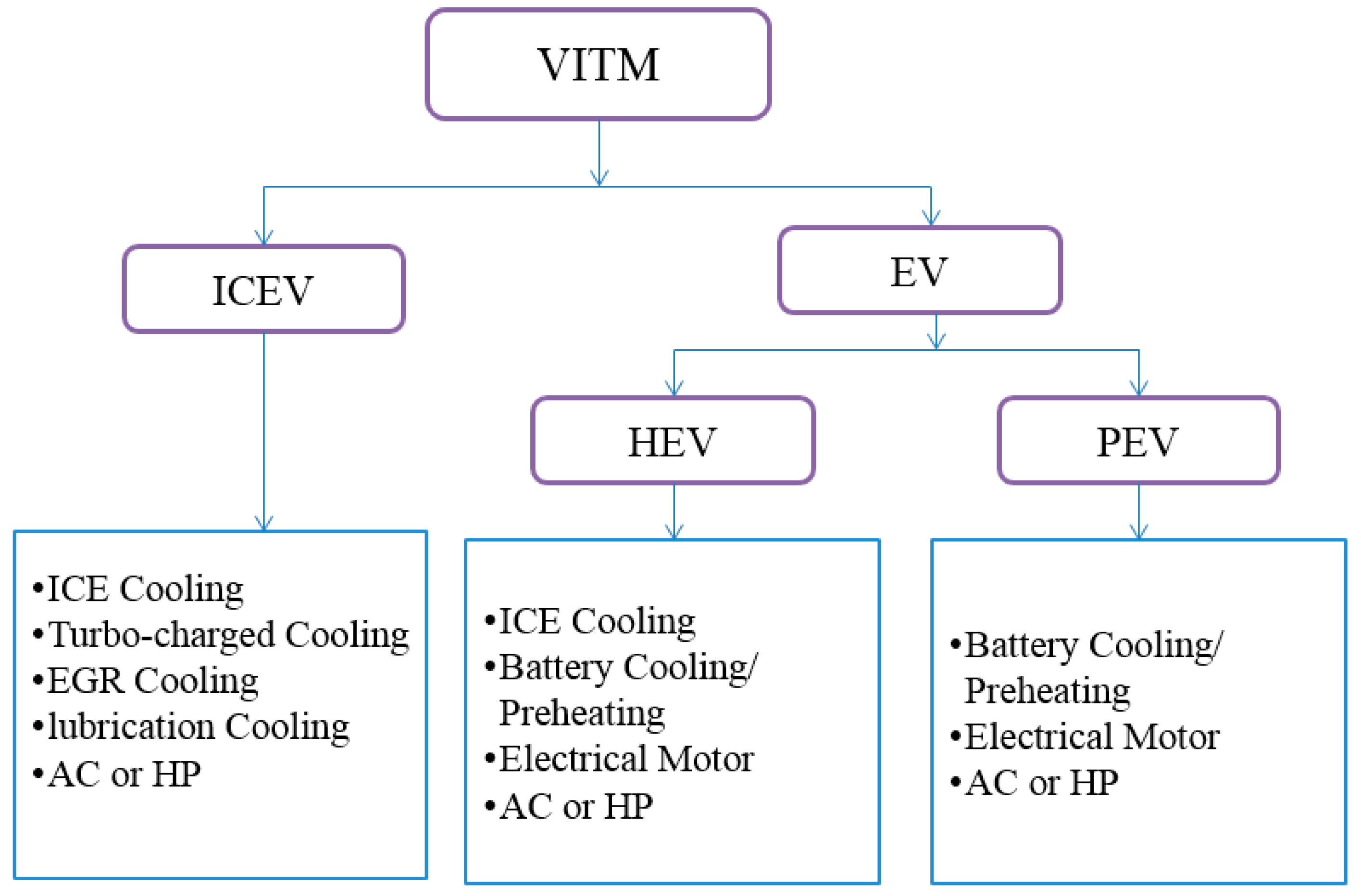
Figure 2.
Typical thermal management schematics diagram of internal combustion engine vehicle (ICEV).
Figure 2.
Typical thermal management schematics diagram of internal combustion engine vehicle (ICEV).
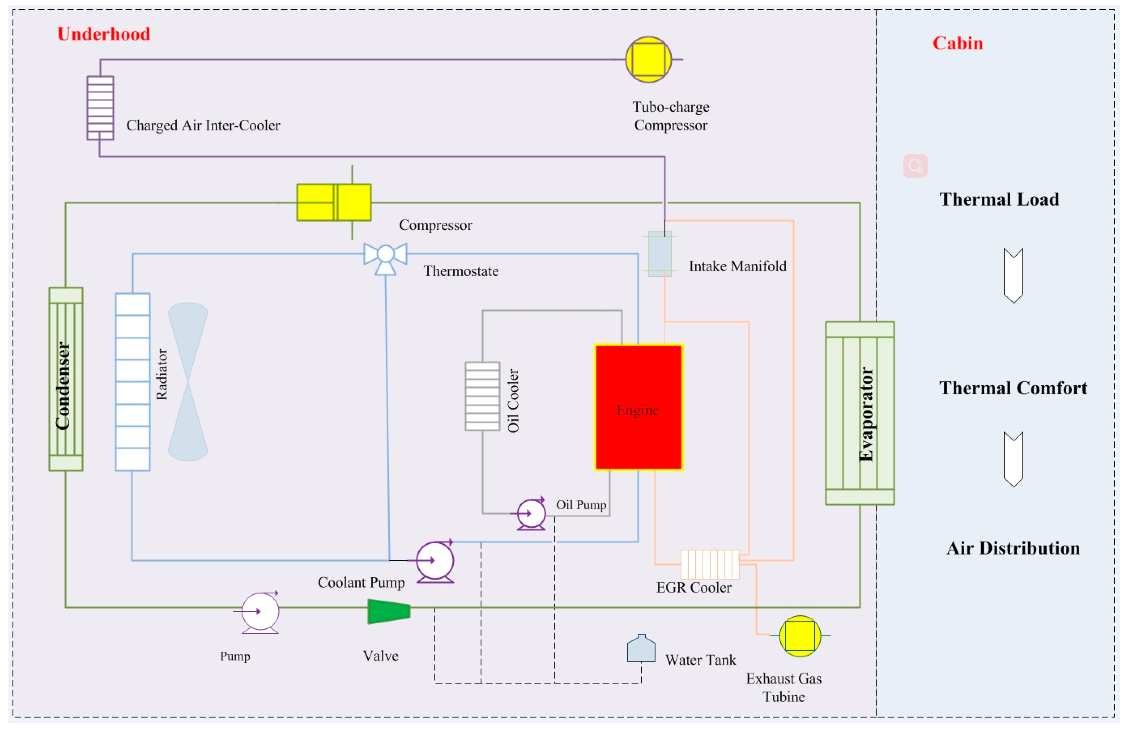
Figure 3.
Typical thermal management schematics diagram of pure electric vehicle (PEV).
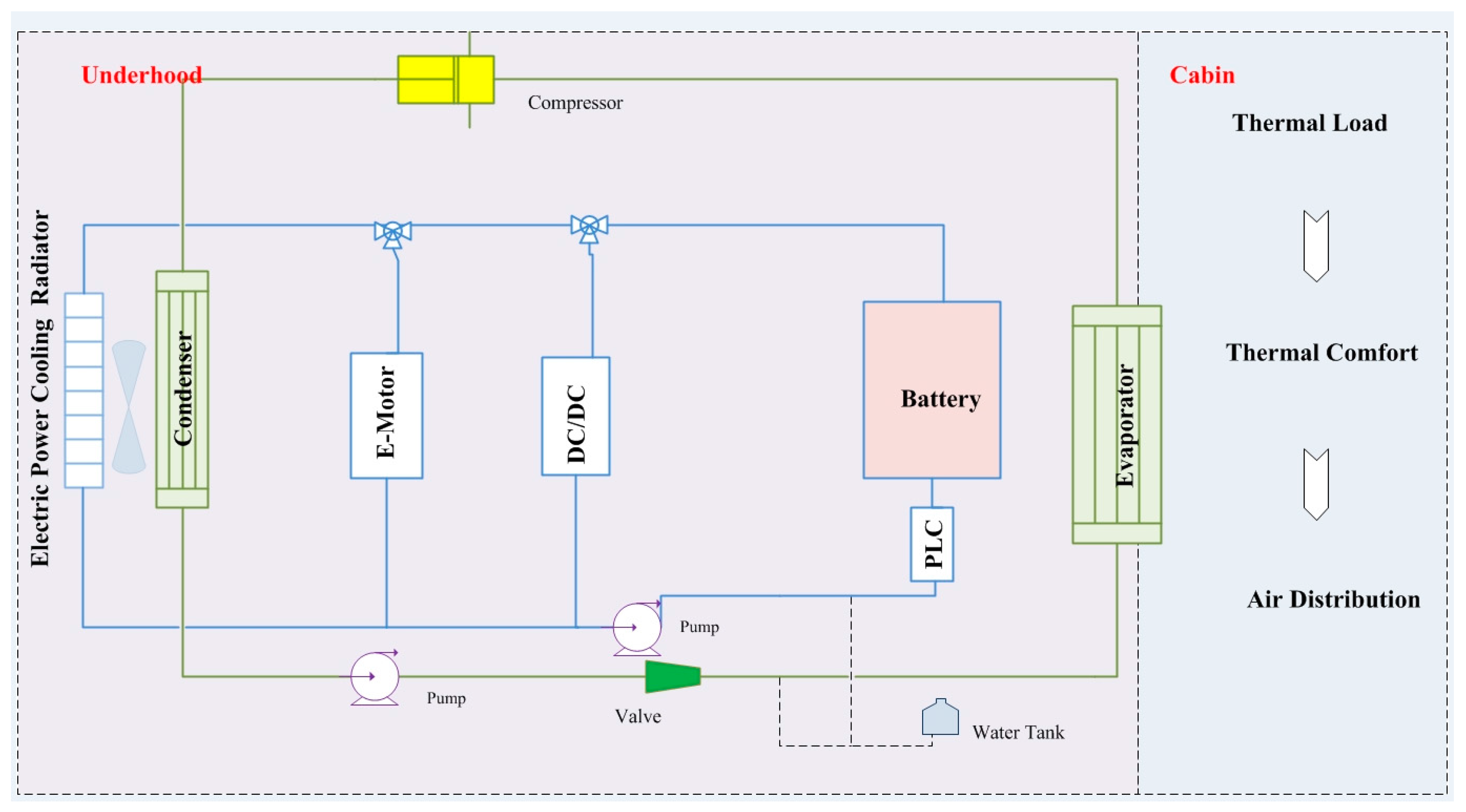
Figure 4.
Typical thermal management schematics diagram of hybrid electric vehicle (HEV).
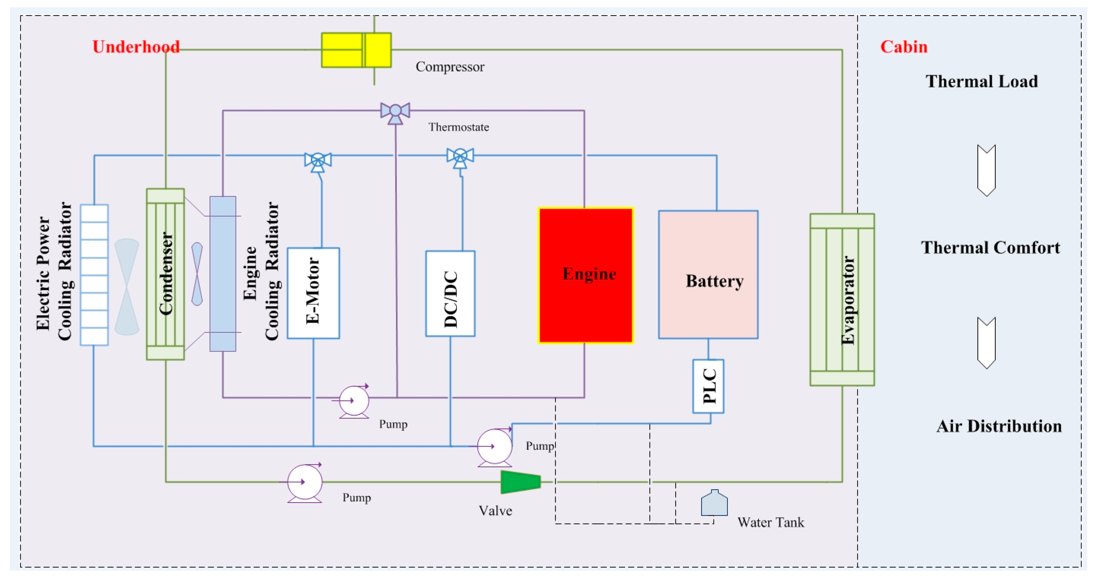
Figure 5.
Schematic diagram for the “SLIM” ITM [78].
Figure 5.
Schematic diagram for the “SLIM” ITM [78].

Figure 6.
Sketch of the Chevrolet Volt ITM [130].
Figure 6.
Sketch of the Chevrolet Volt ITM [130].
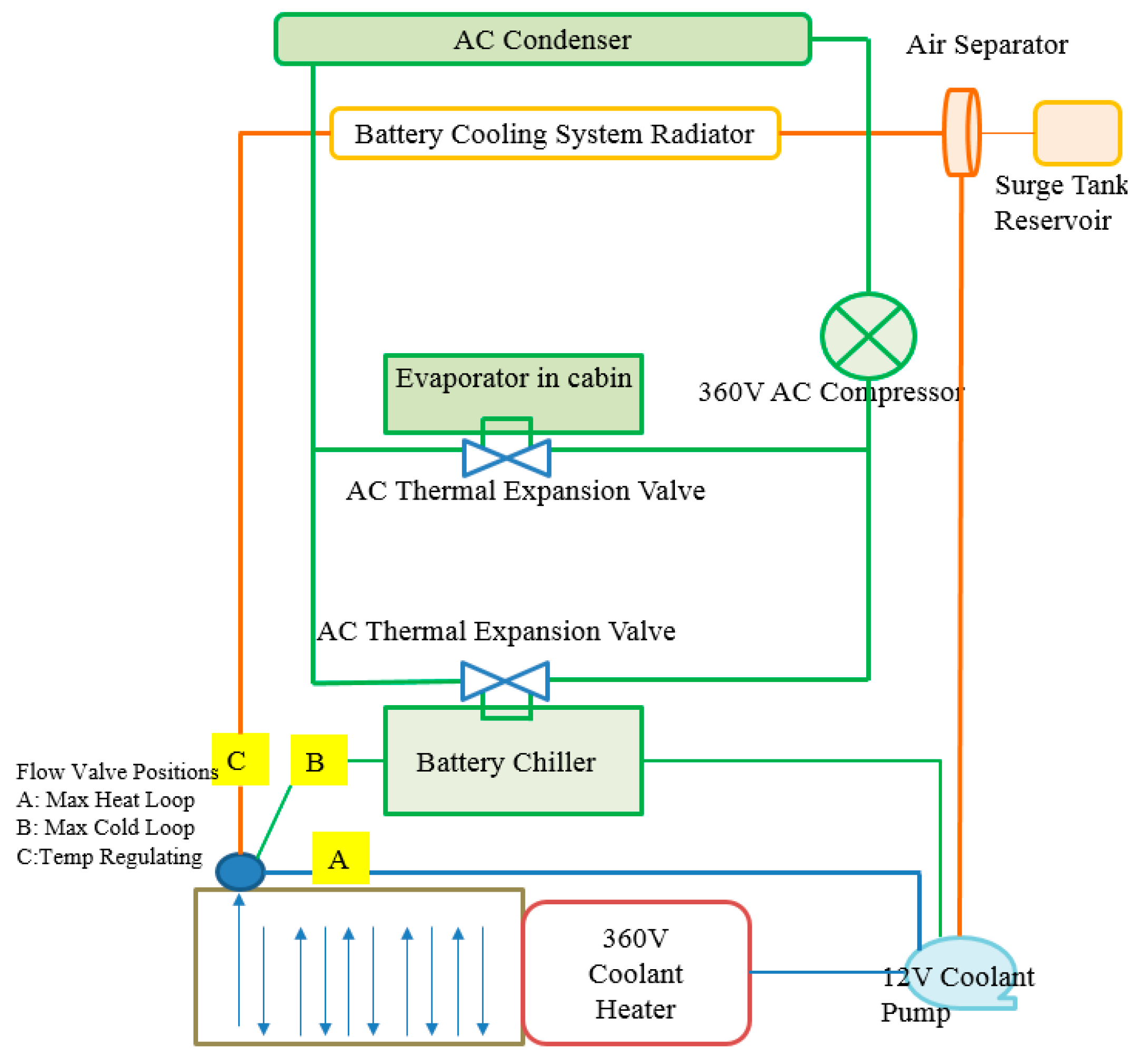
Figure 7.
The ITM system of the NREL CFL [131].
Figure 7.
The ITM system of the NREL CFL [131].
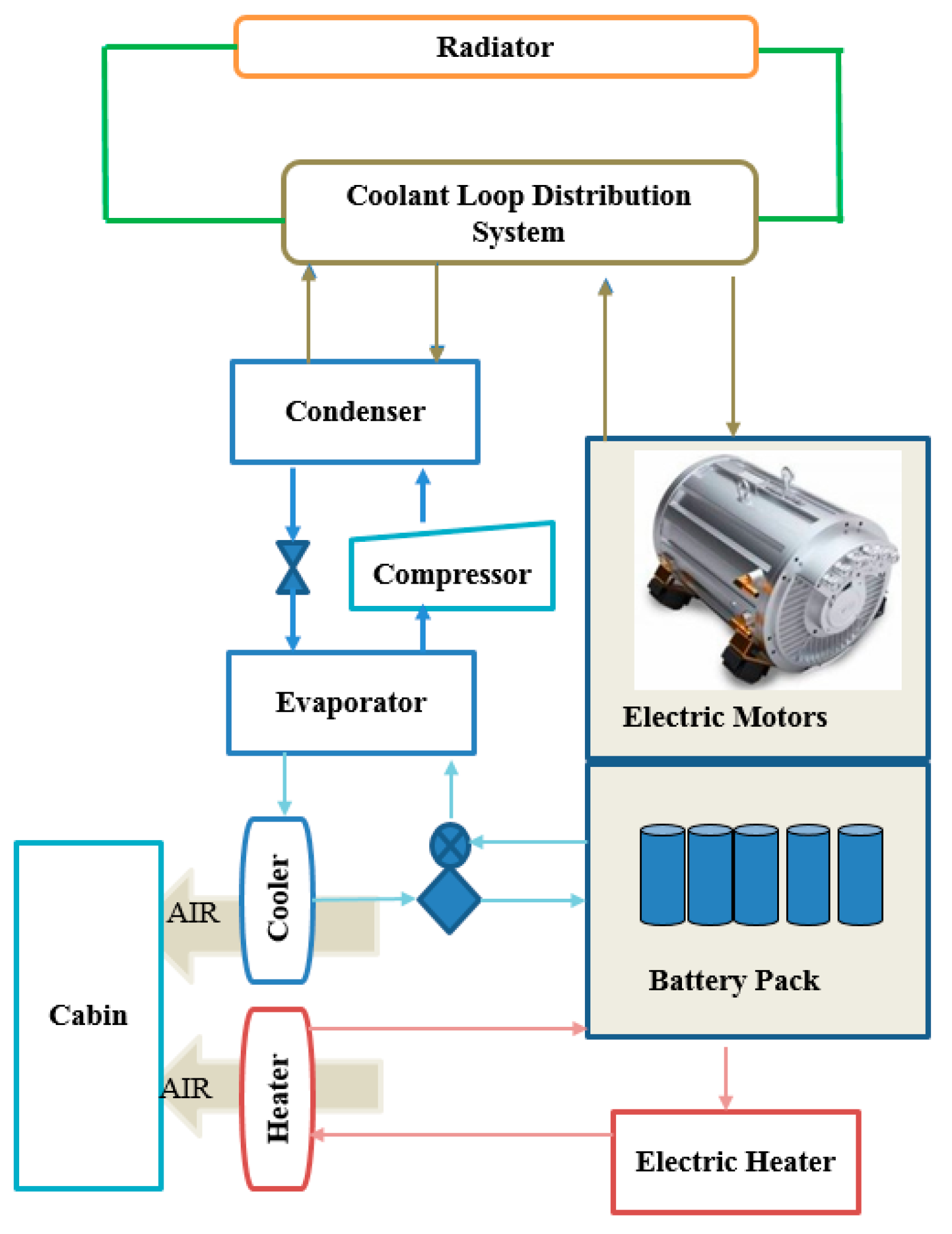
Figure 8.
ITM introduced by NREL [151].
Figure 8.
ITM introduced by NREL [151].

Figure 9.
VITM introduced in [152].
Figure 9.
VITM introduced in [152].
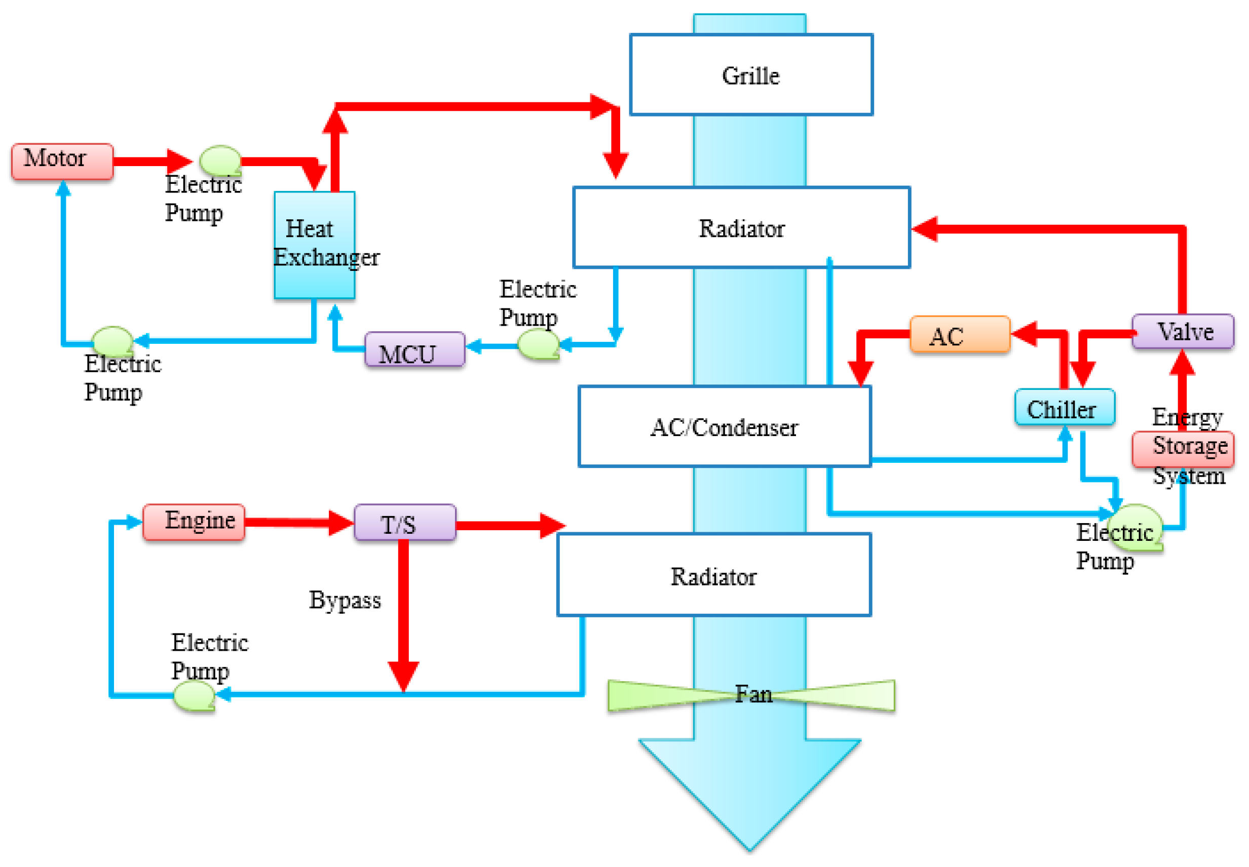
Figure 10.
The schematic diagram of the combination of 1D and 3D scheme of ITM for ICE.

Figure 11.
VITM of underhood cooling and air conditioning.
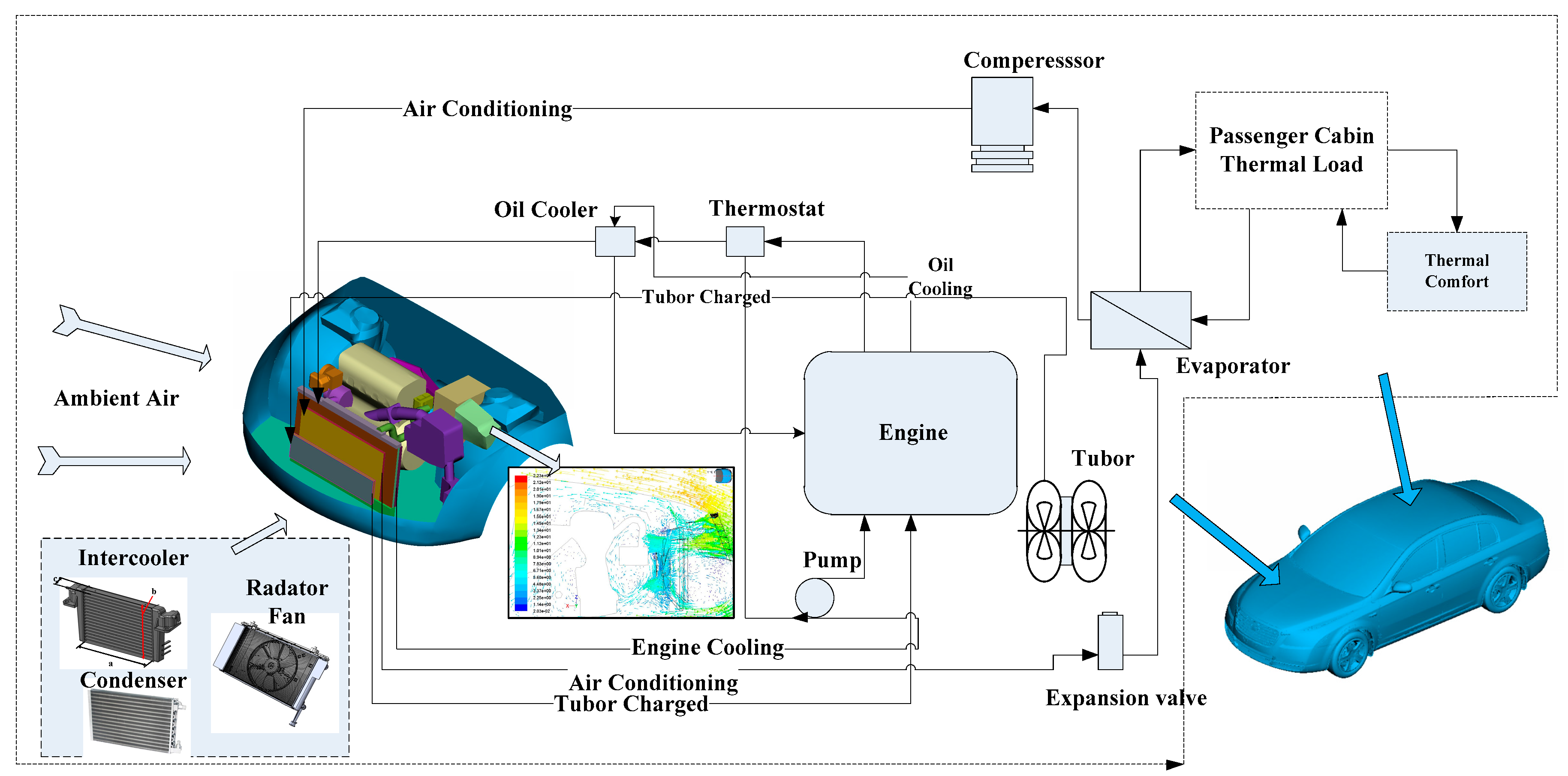
Figure 12.
The schematic diagram the advanced vehicle ITM.

Figure 13.
The data of preheating and cooling.

© 2017 by the authors. Licensee MDPI, Basel, Switzerland. This article is an open access article distributed under the terms and conditions of the Creative Commons Attribution (CC BY) license (http://creativecommons.org/licenses/by/4.0/).
Share and Cite
MDPI and ACS Style
Wang, Y.; Gao, Q.; Zhang, T.; Wang, G.; Jiang, Z.; Li, Y. Advances in Integrated Vehicle Thermal Management and Numerical Simulation. Energies 2017, 10, 1636. https://doi.org/10.3390/en10101636
AMA Style
Wang Y, Gao Q, Zhang T, Wang G, Jiang Z, Li Y. Advances in Integrated Vehicle Thermal Management and Numerical Simulation. Energies. 2017; 10(10):1636. https://doi.org/10.3390/en10101636
Chicago/Turabian StyleWang, Yan, Qing Gao, Tianshi Zhang, Guohua Wang, Zhipeng Jiang, and Yunxia Li. 2017. "Advances in Integrated Vehicle Thermal Management and Numerical Simulation" Energies 10, no. 10: 1636. https://doi.org/10.3390/en10101636
Note that from the first issue of 2016, this journal uses article numbers instead of page numbers. See further details here.