1. Introduction
In the context of increasing demand for electric power, local energy production through the integration of microgrids (MGs) in the main grid is becoming an interesting research topic. MGs are formed by various distributed generators (DGs), energy storage systems (ESS) and controllable loads. Distributed Generators can include Renewable Energy Sources (RESs). There are several renewable generation technologies that can provide electricity in a distributed manner, including photovoltaic (PV) systems, micro hydropower, small-scale biomass facilities, small wind turbines, etc. MGs can operate either in grid-connected or in islanded mode, i.e., connected or disconnected from the Point of Common Coupling (PCC). An MG can be disconnected from the main grid in the case of faults [
1,
2]. Once the fault has disappeared, it can be reconnected to the grid. In addition, a microgrid has its own control system to ensure the correct operation and coordination of the different devices.
Currently, MGs have several configurations: AC, DC or Hybrid AC/DC. However, in some applications DC microgrids have become more attractive than traditional AC microgrids [
3,
4] because of their higher energy efficiency, their ability to easily connect DC/DC converters to the common DC bus, and their ability to directly couple DC power sources, like batteries and PV sources, with DC loads, which results in a reduction of power conversion losses and costs [
4]. Moreover, the control system of DC/DC converters connected to DC microgrid does not have to deal with the problems caused by reactive power flow, synchronization and frequency regulation [
5]. A DC microgrid can operate in grid-connected mode by means of an InterLinking Converter (ILC), which connects the DC bus to the PCC of the main grid [
6,
7]. In this mode, the DC bus voltage is regulated by the ILC, being highly stable, even in the case of low quality distribution grids [
8]. When the distribution grid fails, the microgrid must regulate the DC bus voltage without the ILC. Some control methods have been developed and proposed in the literature [
9,
10,
11] for reaching this goal. The typical objectives of the DC microgrid in grid-connected mode are: to minimize the cost of the imported energy from the main grid, to optimize the power dispatch among the converters and the DC bus and to regulate the DC bus voltage [
12]. For the optimization of the power dispatch, communications between the devices of the MG and the grid operator are necessary [
13,
14].
Regarding the control system, one of the main challenges in MGs is how to maintain the generation and consumption energy balance [
15]. Power imbalance is a common scenario in MGs, which is caused by the discontinuous power generation availability caused in turn by the intermittent nature of renewables and the variable power demand of the loads connected to the MG, among other factors. These imbalances should be managed fast, safely and effectively by the MG control in order to avoid electrical transients, which can damage or destabilize the system [
6,
7,
8]. Therefore, proper power management control strategies have been developed. These strategies are aimed mainly at: (i) controlling the connected DGs and energy storage system, (ii) regulating the DC bus voltage, (iii) optimizing the power dispatch between DC/DC converters and the DC bus voltage to minimize the cost of imported energy from the main grid, (iv) managing and optimizing the ESS operation, and (v) managing current sharing between parallel converters [
16,
17]. At present, the major control strategies to maintain power balance in DC microgrids are the well-known droop control methods [
14,
15,
16,
17,
18], which don’t require any communication infrastructure, or other solutions using communications [
2]. The power management of MGs can be classified into three categories: centralized, decentralized and distributed control [
17,
18,
19,
20,
21]. Centralized control systems offer a higher precision of the power sharing among the power converters in MGs [
20,
21]. In those systems, the energy dispatch can be observed and managed by an intelligent centralized system [
22,
23]. A microgrid central controller (MGCC) acquires system data and takes decisions about the power to be managed by each of the power converters under operation, forecasting power references to all the power devices of the MG such as DGs, loads, ESS, etc. In the case of communication lost or even the failure of the MGCC, local autonomous controllers are necessary. These controls have been explained in many previous works [
24,
25,
26,
27], most of them being based on some droop strategies [
14]. It is worth pointing out that this paper is focused on a centralized MGCC algorithm. A future work could deal with the coordinated operation of the centralized algorithm with local droop controllers in the case of system failures. However, that study is beyond the scope of this paper. Besides, some previous works [
1,
20] recommend centralized solutions for small scale microgrids.
Up to the present different centralized control strategies of microgrids have been proposed in the literature [
28,
29,
30]. In [
28], a control strategy for a DC microgrid was proposed. The strategy was aimed at minimizing the daily total energy costs. In [
29], an optimization algorithm was applied to a group of interconnected MGs with the main grid. The procedures under study were charging/discharging of the ESS, starting or stopping the DGs, and receiving/sending power from/to neighboring MGs. In this case, the charge and discharge of the ESS relies on the energy demand and production. A centralized system for a DC distribution system was presented in [
30]. The main objective of that control method was cost minimization based on the real-time electrical price. In order to meet that goal, converter control was based on voltage droop, which achieved the power sharing among the DGs and was responsible for tracking the DC bus voltage reference. In [
31], a coordinated control strategy was addressed within a DC microgrid. In that case the converters were working as voltage sources. A virtual output resistance was implemented for each converter. However, no communications were implemented, which are necessary to optimize the power dispatch among the power converters and to restore the voltage deviations produced [
14].
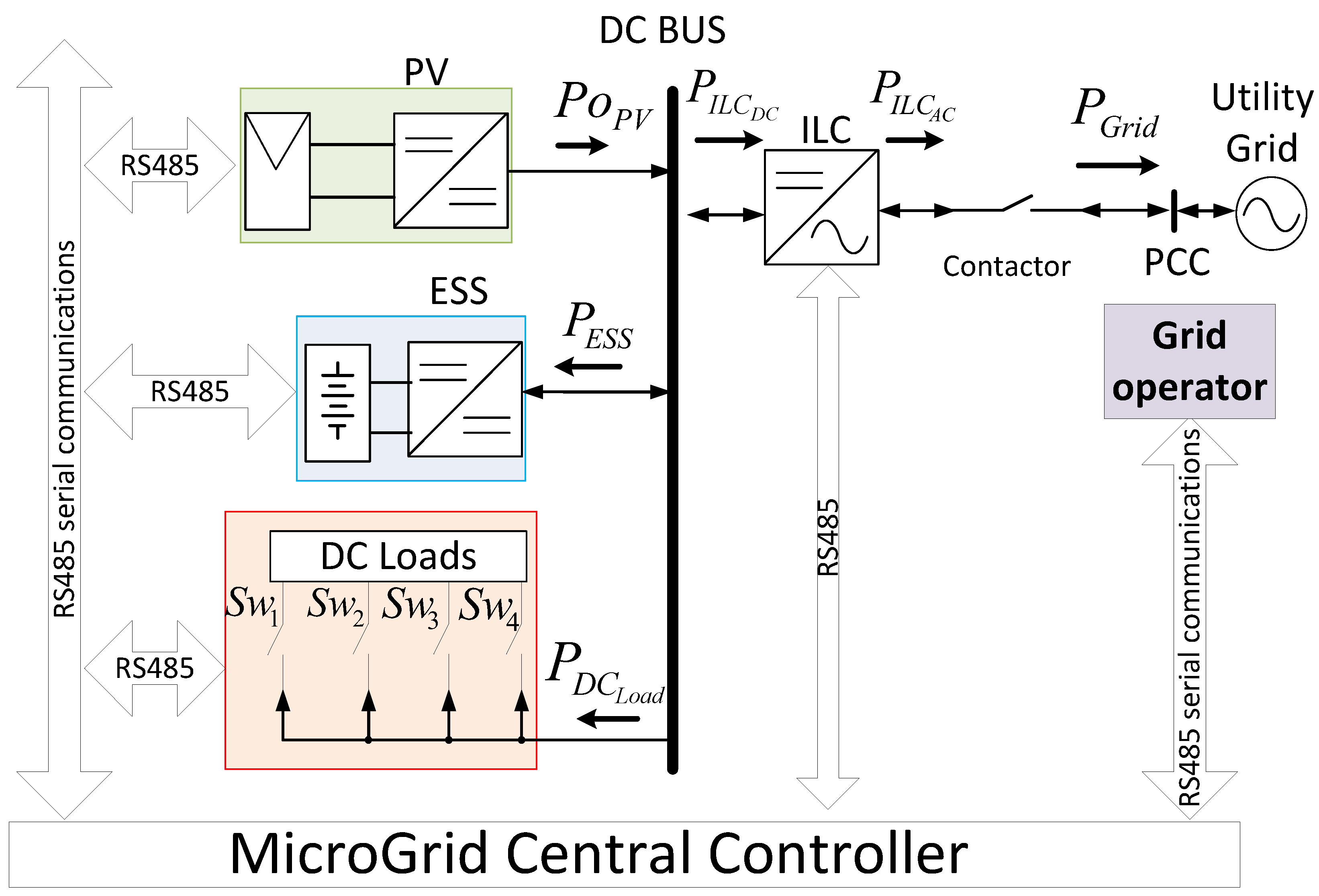
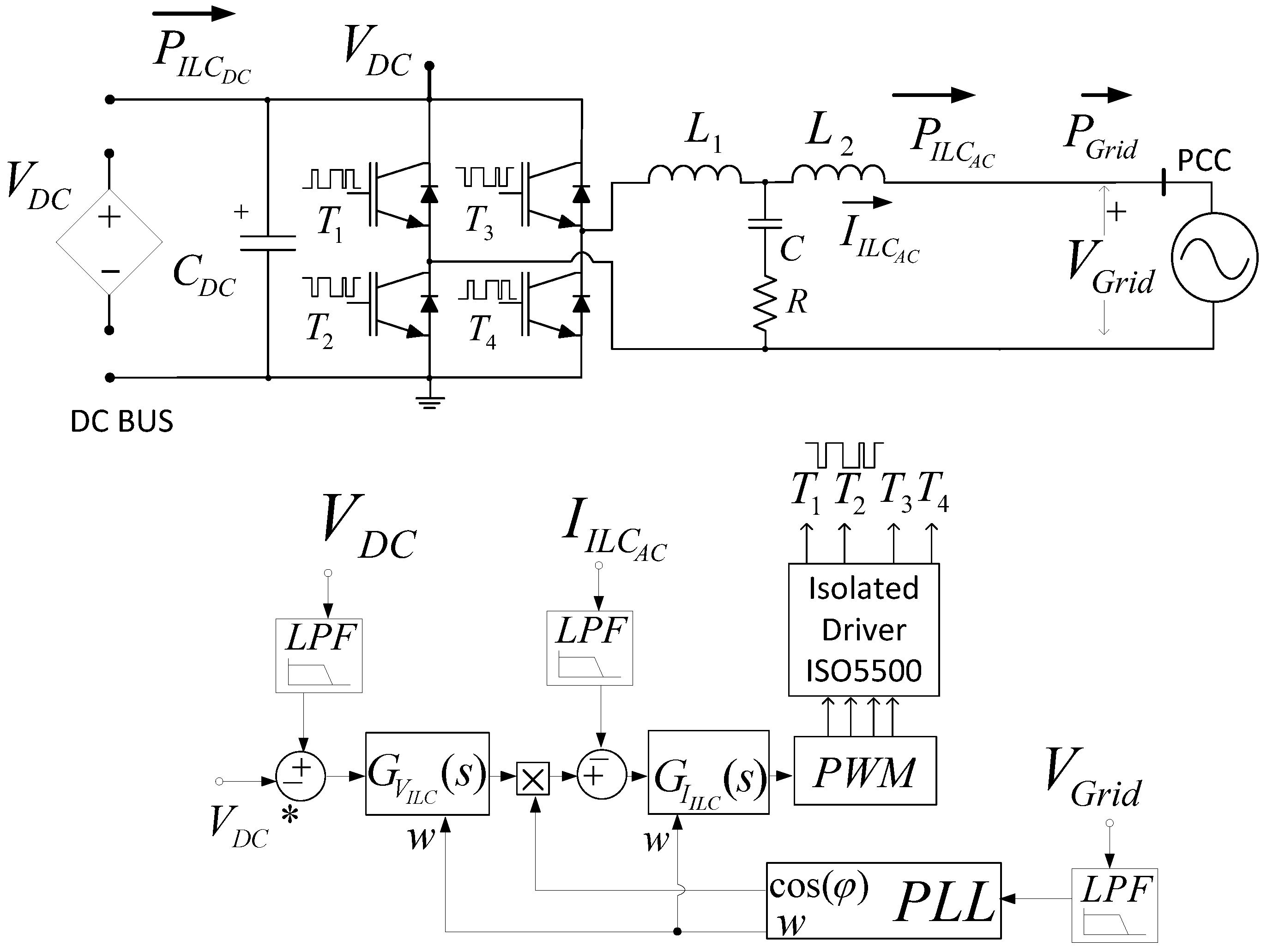
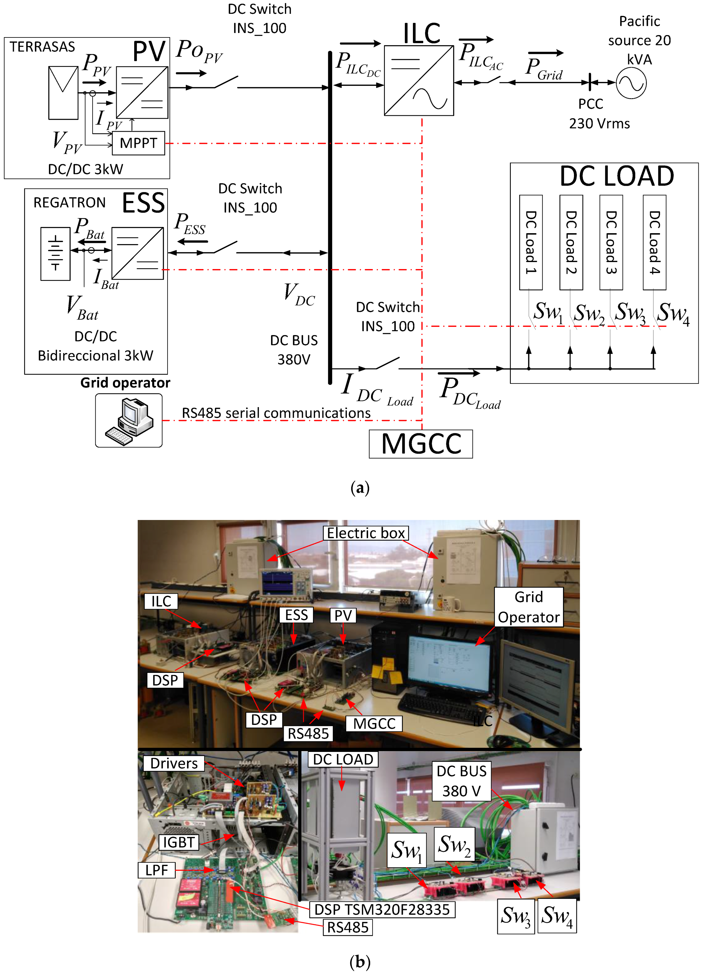
As it was described above, several centralized management and control strategies have been developed for DC microgrids. The strategies have been implemented by solving partial problems or using a particular control strategy. In this work, a centralized control technique for the efficient power management of an experimental DC microgrid is explained. The proposed DC microgrid is connected to the main grid through a bidirectional ILC (see Figure 1). The ILC is an AC/DC bidirectional converter which is responsible for managing the power flow between the DC bus and the main grid. The ILC regulates the DC bus voltage at a fixed value.
In this work, the MGCC does not account for the cost-effective operation of the system in terms of the energy tariffs. The MGCC receives information about the power exchange limits with the main grid from the grid operator. The power to be injected/extracted to/from the grid is calculated by an algorithm implemented in the MGCC starting from the knowledge of the PV available power, the load connected to the DC bus, the battery state and the power exchange limits provided by the grid operator. The goal of that algorithm is to import the needed power from the grid, keeping it below the established limits, feeding the loads and keeping the batteries SoC inside a safe range. If a surplus of energy is available from the PV generation, power is injected to the grid below the limit imposed by the grid operator. No energy price considerations are taken into account by the implemented algorithm.
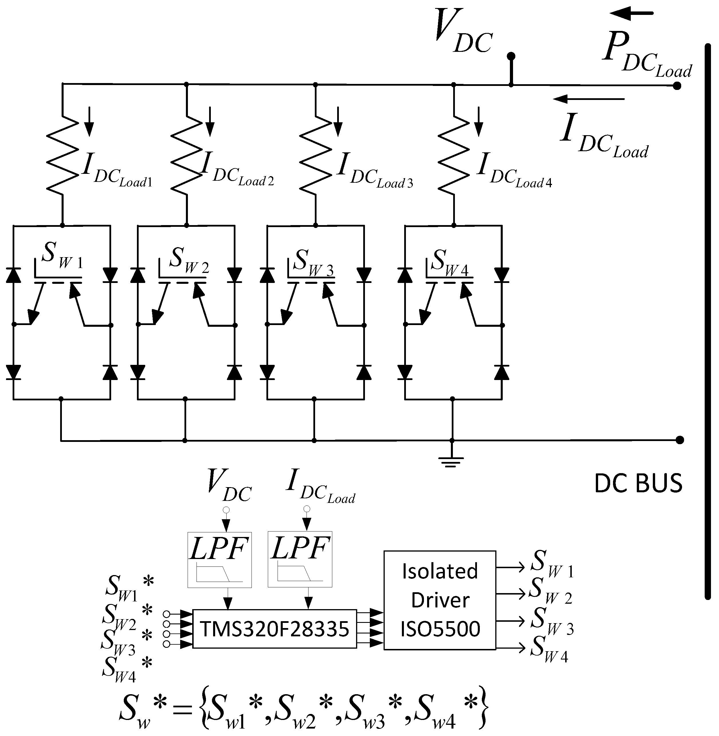
As shown in Figure 1, the DC microgrid consists of: (a) an MGCC; (b) an ILC connected to the main grid which controls the DC bus voltage; (c) two DC/DC converters that operate as a current source interchanging their power with the DC bus; (d) four loads with their respective electronic switches; (e) an RS-485 serial communication system and (e) the grid operator.
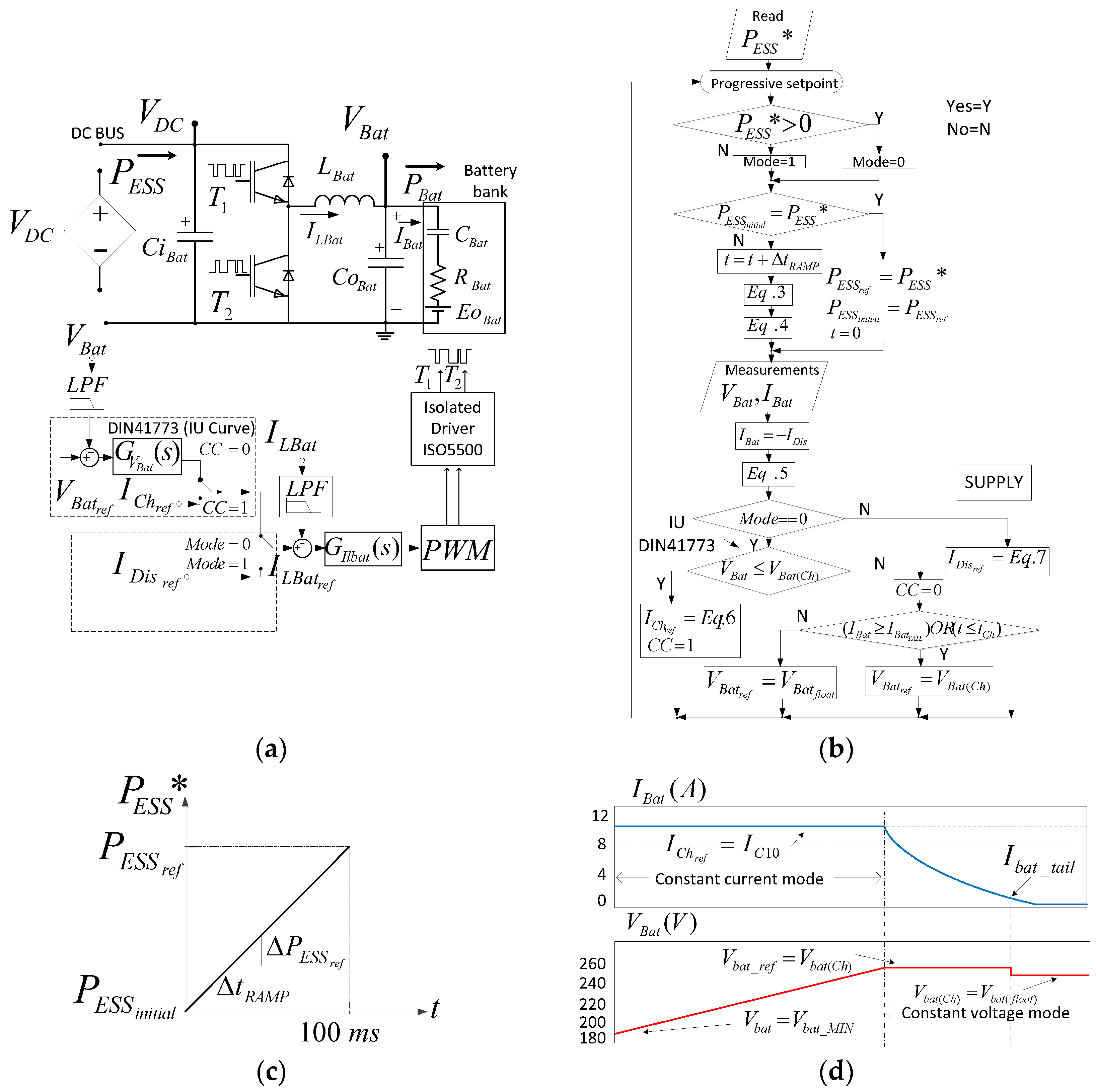
The main contribution of this paper is the integration of conventional control strategies of all the power converters in the microgrid by means of a centralized algorithm implemented in a MGCC, taking into account real time serial communications for sending/receiving the necessary data. An additional contribution of this work is the use of a realistic battery ESS control algorithm in the context of DC microgrids, which follows the charging procedure DIN 41773 [
32,
33]. Depending on their voltage, the batteries are charged either at a constant current or at a constant voltage. Once the current absorbed by the batteries is smaller than a pre-specified value of tail current, the battery voltage is kept at a certain float voltage. The integration of a load management algorithm, compatible with the microgrid status, is also described. The integration of all those strategies through an MGCC has not been reported by previous studies, to the best authors’ knowledge. It is worth pointing out that most of previous studies for this kind of MG are theoretical, having been validated by simulation results [
4,
28,
29,
30,
31,
34,
35]. In this paper, the experimental validation of the MGCC centralized algorithm in a DC microgrid is shown. It provides a realistic evaluation under different MG operation scenarios. Moreover, this work shows the MGCC algorithm runtime as well as the communication delays in order to ensure the stability of the DC bus.
Thus, the main objectives of the control strategies applied to the DC microgrid are the following:
- -
To comply with the power flow limits from/to the DC microgrid to/from the main grid. These limits are established by the grid operator and are set according to the purchase or sale tariffs of generated or consumed energy. This study takes into account the limit value of the power absorption/injection sent by the grid operator to the MGCC, as well as its effect on the general MG power management and on the power converters electrical behavior.
- -
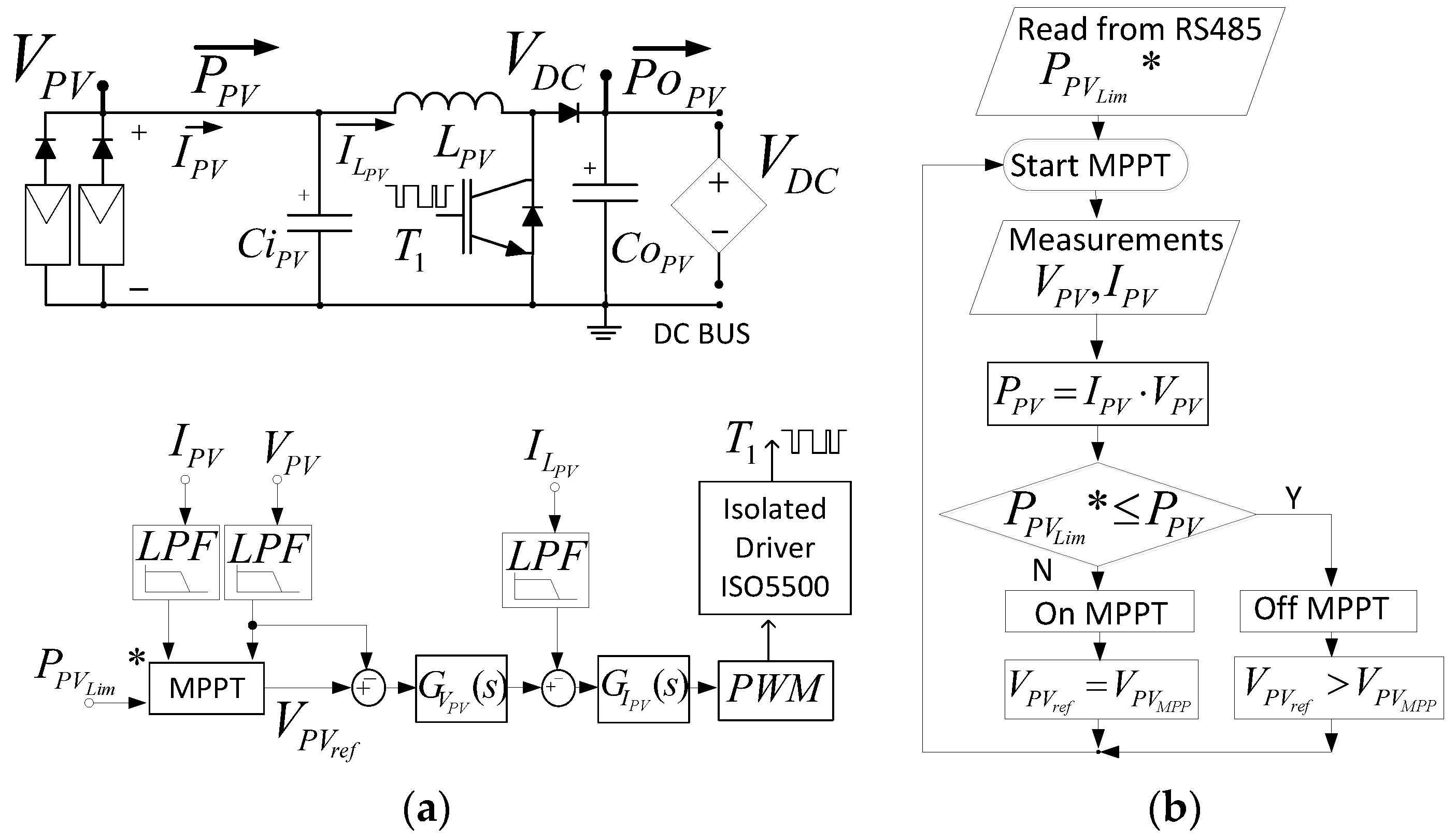
To limit the photovoltaic power generation below the maximum available power if it is required. This limit depends on the power available in the DC bus and the power injection limit set by the grid operator.
- -
To develop the charging procedure DIN 41773 for Valve Regulated Lead-Acid (VRLA) [
36] batteries of the ESS connected to the DC bus, in order to ensure the proper operation of the ESS and extend the life of its batteries.
- -
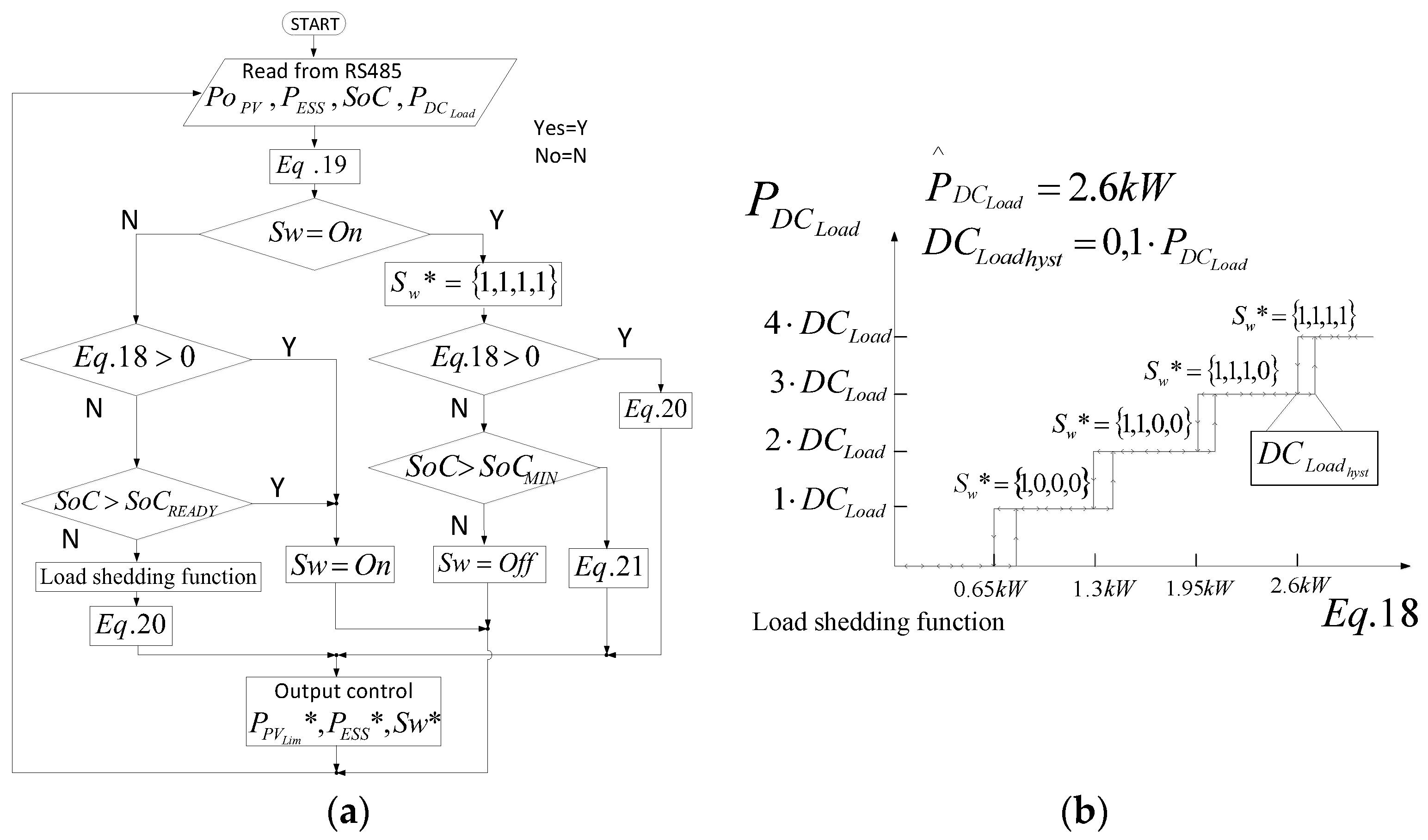
To manage the power demand of the devices connected to the DC bus by means of a load shedding functionality. This function, which is used only as a last resort, is applied according to the batteries status, the available power and a pre-established power threshold. The pre-established thresholds have a hysteresis level when connecting/disconnecting, avoiding destabilizing transients at the DC bus.
- -
To control in real time the power flow inside the MG through RS485 serial communication. The proposed power management algorithm provides the optimal reference values, which are transmitted to each converter to establish their operation.
- -
To obtain smooth transients in the voltages and currents of the power converters connected in the DC bus, during the sudden changes of the power set points in each converter.
This paper is organized as follows:
Section 2 describes the primary controls of every power converter of the DC microgrid. In
Section 3, concepts related to the power management algorithm are explained. In
Section 4, experimental and discussion results are presented. Finally, the conclusions are presented in
Section 5.
4. Experimental Results and Discussion
Several experimental power electronic converters have been built for validating the power management strategies devised in this study. The power converters and PV panel specifications are shown in the
Table 3. The following devices have been connected to the DC bus of the MG available in the lab: a 3 kW battery ESS, a 2.5 kW PV source and four electronic switches to connect/disconnect four DC loads of 650 W each one. The connection of the DC bus and the grid is performed by a single-phase ILC of 10 kW that works in grid-connected mode.
Figure 8a,b show the schematic diagram and a picture of the experimental DC microgrid, respectively. The batteries have been emulated by a bidirectional DC source/battery emulator model TC.GSS-Bidirectional-DC-PSU from Regatron AG (Rorschach, Switzerland). The PV array has been emulated by means of a 10 kW PV array simulator TerraSAS ETS1000/10 from Ametek (San Diego, CA, USA). The LabView software (National Instruments Spain, Madrid, Spain) is used for emulated the grid operator, for the initializing/stopping sequence and the monitoring the power dispatch of the DC microgrid. Several scenarios have been studied in order to demonstrate the suitable behavior of the DC microgrid in its most common and critical situations. In the scenarios under study step changes of the irradiation, DC load,
SoC and power limits have been considered, as it can be observed in the following graphics.
Four experiments have been carried out.
Figure 9,
Figure 10 and
Figure 11 depict the waveforms of the currents, voltages and powers of the power converters composing the DC bus of the MG corresponding to experiments #1 to #3, respectively.
Figure 12 corresponds to experiment #4 and depicts the waveforms and delays of the communication system of the MG. Experiments #1 to #3 show the behavior of the system with the same change of the irradiation level at the PV source, except with a different
SoC of the ESS. The power dispatch limits established by the grid operator from the grid to the DC bus by the ILC is
PILC_DC = −1 kW in all the experiments. The hysteresis level for comparisons is:
DCLoad_hyst = 260 W.
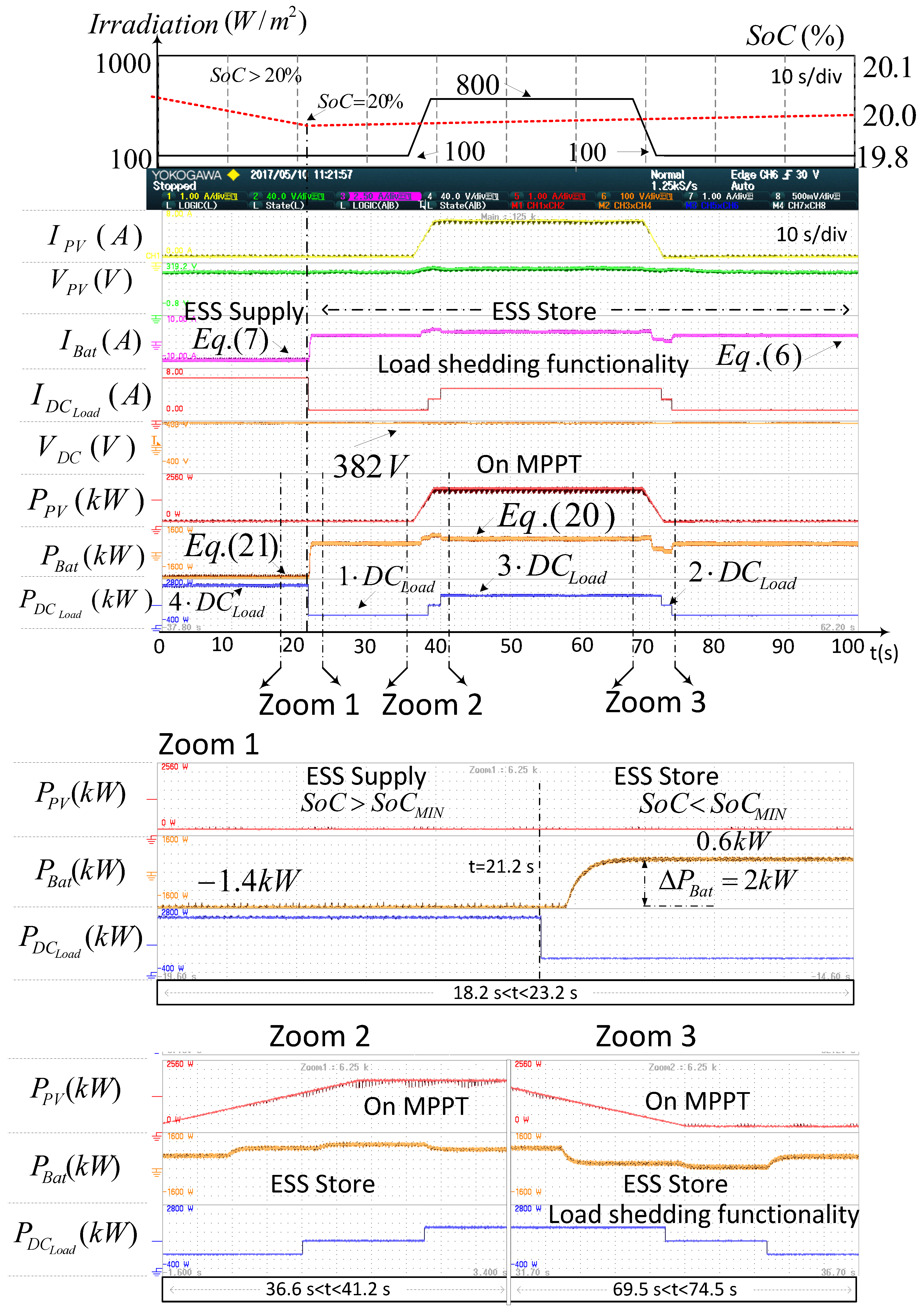
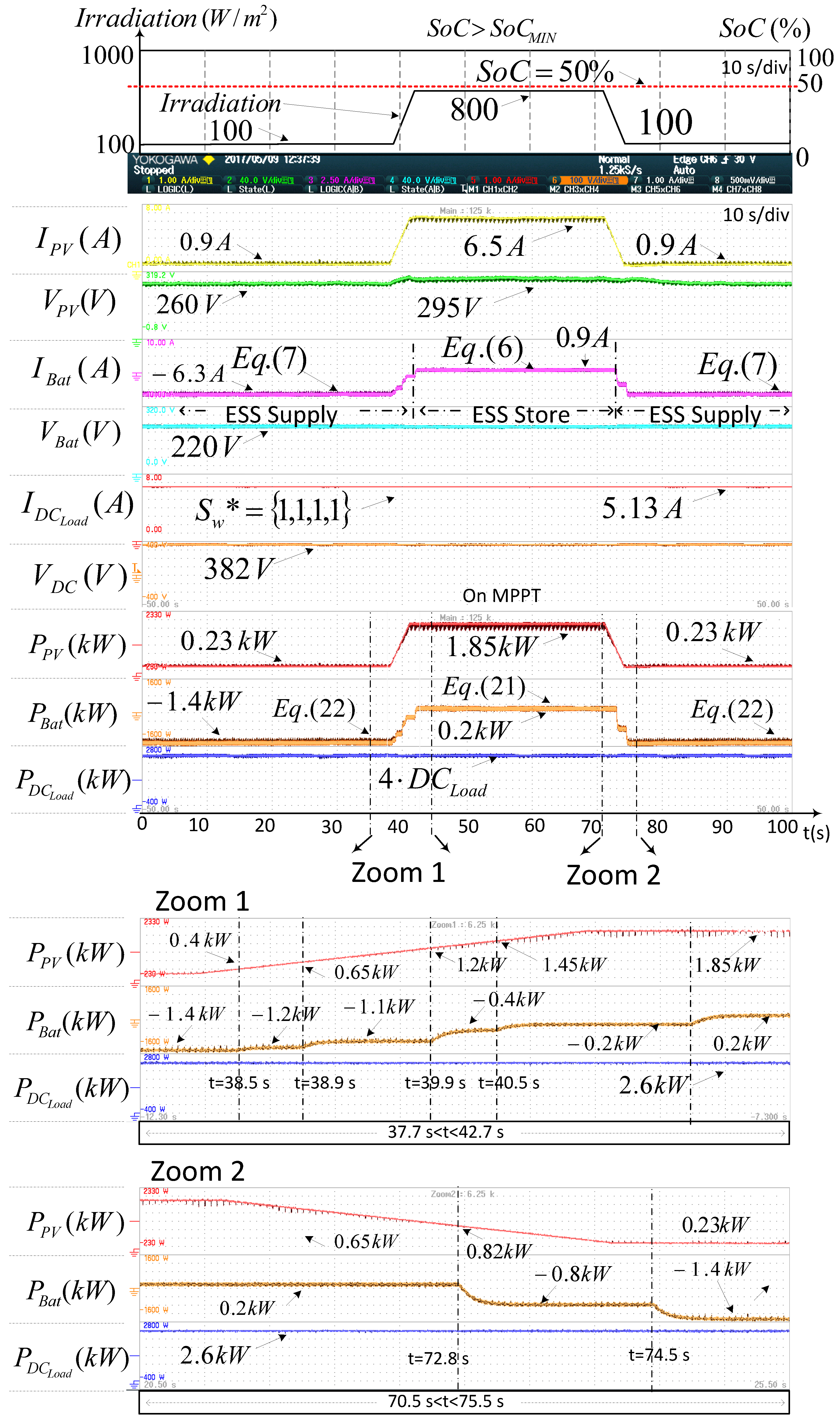
4.1. Experiment #1
The ESS is initially at a
SoC ≥
SoCMIN. In
Figure 9 can be observed that four loads keep connected during the whole experiment, (
PDC_Load = 2.6 kW). Two zoom images can be observed in the lower plot from
Figure 9. In Zoom 1, it is shown the detection by the MGCC of an increase in PV system generation. In Zoom 2 it is shown the detection of a decrease in PV system generation. The analysis is performed according to the following time intervals:
Interval 1.1 (0 s <
t < 38 s): The irradiation level is 100 W/m
2 and the PV source works at its MPP, providing
PPV = 230 W to the DC bus. That irradiation is not enough to feed all the DC loads. Taking into account that the ESS is charged (
SoC ≥ 50%) the MGCC transfers the maximum possible power from the grid (
PILC_DC = −1 kW) to the DC bus through the ILC. MGCC keeps all the DC loads connected and orders the ESS deliveries all the power required by the DC bus,
PBat = −1.4 kW. See
Figure 9.
In Zoom 1 of the
Figure 9, at
t = 38.5 s; MGCC detects an increase of PV system generation, the PV source works at its MPP delivering
PPV = 0.4 kW. The MGCC transfers the maximum possible power from the grid (
PILC_DC = −1 kW), and keeps all the DC loads connected (
PDC_Load = 2.6 kW). ESS supplies all the power required by the DC bus, the power delivered by the ESS is reduced to
PBat = −1.2 kW.
At t = 39.9 s; MGCC detects increasing generation, the PV source works at its MPP delivering PPV = 1.2 kW. The MGCC transfers the maximum possible power from the grid (PILC_DC = −1 kW), and keeps all the DC loads connected (PDC_Load = 2.6 kW). ESS supplies all the power required by the DC bus, the power delivered by the ESS is reduced to PBat = −0.4 kW.
At t = 41 s the PV source works at its MPP delivering PPV = 1.85 kW, being PILC_DC = −1 kW. At that instant the MGCC detects that the available power at the DC bus to feed all the DC loads is higher than the hysteresis level (Equation (18) ≥ 0).
Interval 1.3 (41 s < t < 70.5 s): The irradiation level is 800 W/m2 and the PV source works at its MPP, providing PPV = 1.85 kW to the DC bus. The MGCC forces the ESS to change its operation to energy storage mode, the batteries are charged with a current given by (6). The ESS changes the setpoint ICh_ref, until the available power is stable (At t = 42 s, PBat = 0.2 kW).
Interval 1.4 (70.5 s <
t < 75.5 s): The irradiation decreases from 800 W/m
2 to 100 W/m
2 in 3 s. See Zoom 2 of the
Figure 9.
At t = 72.8 s the PV source works at its MPP, providing PPV = 0.82 kW to the DC bus. Taking into account that the ESS is charged (SoC > 50%). The MGCC forces the ESS to change its operation to supply mode, the batteries are discharged with a current given by Equation (7). The ESS changes the setpoint IDis_ref, until the available power generation is stable (At t > 74.5 s, PBat = −1.4 kW).
4.2. Experiment #2
The ESS is initially at a
SoC ≤ 20% (discharged). MGCC applies the load shedding functionality; see
Figure 10. Two zoom images can be observed in the lower plot from
Figure 10. In Zoom 1 it is shown the detection by the MGCC of an increase in PV system generation. In Zoom 2 it is shown the detection of a decrease in PV system generation. The analysis is performed according to the following time intervals:
Interval 2.1 (0 s < t < 28 s): The irradiation level is 100 W/m2 and the PV source works at its MPP, providing PPV = 230 W to the DC bus. That irradiation is not enough to feed all the loads. Considering that the ESS is discharged (SoC < 20%), the MGCC transfers the maximum possible power from the grid (PILC_DC = −1 kW) to the DC bus through the ILC, and applies the load shedding functionality. Taking into account that the available power at the DC bus (1.28 kW) is not enough to feed two loads, the MGCC connects only one DC load (PDC_Load = 0.65 kW), using the rest of this power for charging the batteries at PBat = 0.55 kW.
Interval 2.2 (28 s <
t < 31 s): The irradiation increases from 100 W/m
2 to 800 W/m
2 in 3 s, which makes the MGCC to apply the load shedding functionality. See Zoom 1 of
Figure 10.
At t = 29 s the PV source works at its MPP delivering PPV = 0.95 kW, whereas PILC_DC = −1 kW. At that instant the MGCC detects that the available power at the DC bus is enough to feed two of the loads (PDC_Load = 1.3 kW). The MGCC takes into account the hysteresis level in that connection and changes the setpoint PESS * from 0.55 kW to 0.6 kW. Note that at t = 29 s, after the connection of the two loads, only |PILC_DC| ≤ 1 kW is taken from the grid. This ensures a minimum level of power available in the DC bus.
At t = 30.2 s, the PV source works at its MPP delivering PPV = 1.6 kW, being PILC_DC = −1 kW. At that instant the MGCC detects that the available power at the DC bus, taking into account the hysteresis level, is enough to feed three of the loads (PDC_Load = 1.95 kW). The MGCC connects three loads and changes the setpoint PESS * of the ESS from 0.6 kW to 0.65 kW.
Interval 2.3 (55.5 s <
t < 65.5 s): The irradiation decreases from 800 W/m
2 to 100 W/m
2 in 3 s. The MGCC keeps the load shedding functionality activated. See Zoom 2 of
Figure 10.
At t = 64.3 s the PV source works at its MPP delivering PPV = 0.23 kW, whereas PILC_DC = −1 kW. At that instant the MGCC detects that the available power at the DC bus taking into account the hysteresis level is enough to feed two of the loads (PDC_Load = 1.3 kW). MGCC connects two loads and changes the setpoint PESS * of the ESS from 0.65 kW to 0.5 kW. Note that at t = 64.3 s, after the connection of the two loads, only |PILC_DC| ≤ 1 kW is taken from the grid. This ensures a minimum level of power available in the DC bus.
4.3. Experiment #3
The ESS is initially at a
SoC ≥
SoCMIN. At
t = 21.2 s the
SoC changes at a
SoC <
SoCMIN, see
Figure 11. Three zoom images can be observed in the lower plot from
Figure 11. Zoom 1 shows the details of the power flows in the MG when the MGCC detects that
SoC <
SoCMIN. In Zoom 2 it is shown the detection by the MGCC of an increase in PV generation. In Zoom 3 it is shown the detection of a decrease in PV generation. The analysis is performed according to the following time intervals:
Interval 3.1 (0 s < t < 21.2 s): The irradiation level is 100 W/m2 and the PV source works at its MPP, providing PPV = 230 W to the DC bus. That irradiation is not enough to feed all the loads. Taking into account that the SoC > 20%, the MGCC transfers the maximum possible power from the grid (PILC_DC = −1 kW) to the DC bus through the ILC. MGCC keeps all the DC loads connected and orders the ESS supplying all the power required by the DC bus, PBat = −1.4 kW.
At t = 21.2 s; the PV source works at its MPP delivering PPV = 230 W. That irradiation is not enough to feed all the loads. Considering that MGCC detects that the ESS is discharged, SoC < 20%. MGCC transfers the maximum possible power from the grid (PILC_DC = −1 kW) to the DC bus through the ILC. MGCC starts a transition from Sw = On to Sw = Off and applies the load shedding functionality. Taking into account that the available power at the DC bus (1.23 kW) is not enough to feed two loads, MGCC connects only one DC load (PDC_Load = 0.65 kW). The rest of the available power is used for charging the batteries. MGCC changes the setpoint PESS * of the ESS from −1.4 kW to 0.55 kW.
Zoom 1 of
Figure 11 depicts
PBat and its behavior to sudden changes of
PESS * from 1.4 kW to 0.55 kW. If
PESS * is negative, the ESS is supplying power to the DC bus according to Equation (21), whereas if
PESS * is positive, the batteries are charged according to Equation (20).
Interval 3.2 (36.6 s <
t < 41.2 s): The irradiation increases from 100 W/m
2 to 800 W/m
2 in 3 s. See Zoom 2 of the
Figure 11. The MGCC detects an increase in PV generation. The PV source works at its MPP. That irradiation is not enough to feed all the loads. Considering that the ESS is discharged (
SoC < 20%), the batteries are charged according to Equation (20). MGCC transfers the maximum possible power from the grid (
PILC_DC = −1 kW) to the DC bus through the ILC, and applies the load shedding functionality.
Interval 3.3 (68 s <
t < 74.5 s): The irradiation decreases from 800 W/m
2 to 100 W/m
2 in 3 s. See Zoom 3 of
Figure 11. The MGCC detects a decrease in PV generation. The PV source works at its MPP. That irradiation is not enough to feed all the loads. The ESS is still discharged (
SoC < 20%). The MGCC transfers the maximum possible power from the grid (
PILC_DC = −1 kW) to the DC bus through the ILC, and applies the load shedding functionality.
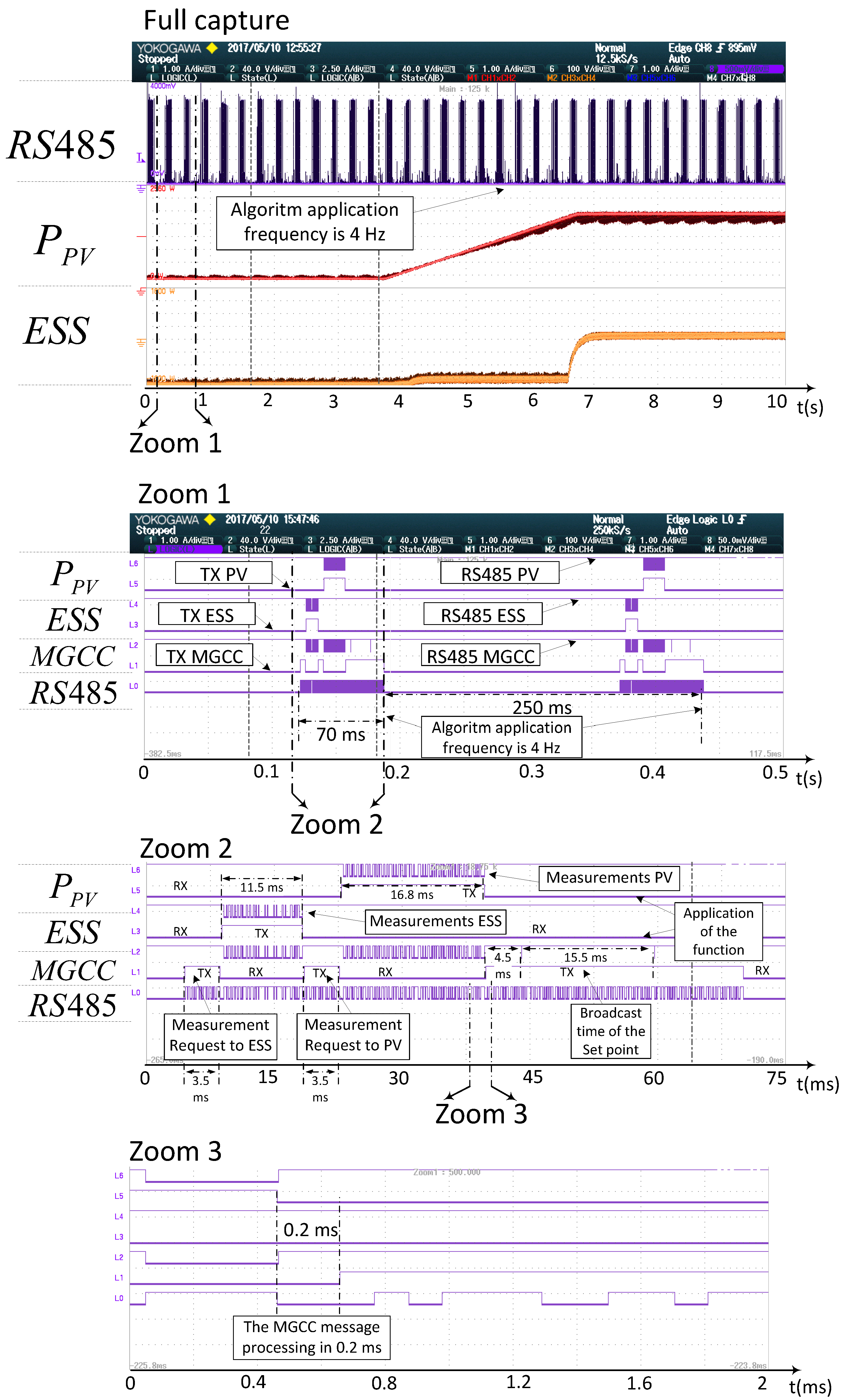
4.4. Experiment #4
The communication delays and the running time of the power management algorithm can be observed in
Figure 12. The RS485 communication bus baud rate is 9600 bps. In the
Figure 12 (full capture) the power management algorithm is executed every 250 ms (4 Hz) performing the following tasks: request the measurements of voltages and currents to all devices in the microgrid, calculation of instantaneous powers references of the devices and the transmission of the references to the devices. The MGCC processing time of these tasks are shown in
Table 4.
Three different zoom times about intervals of the RS485 communication of
Figure 12 (full capture) are shown.
The Zoom 1 of
Figure 12 corresponds to 500 ms, the Zoom 2 of
Figure 12 corresponds to 75 ms and the Zoom 3 of
Figure 12 corresponds to 2 ms. In Zoom 1 of the
Figure 12 it can be observed that the previously described tasks performed every 250 ms by the MGCC are completed in 70 ms. In Zoom 2 of the
Figure 12 it can be observed the detail of the receiving (RX) and transmitting (TX) signals of every microgrid component on the bus RS485: PV generator, ESS, MGCC. In Zoom 3 of the
Figure 12 it is shown the time required for the MGCC from the reception of information of the converters and the compute the reference signals to be sent to each element is 200 µs. The communication transmission delays of the request, response and send operation commands in the DC microgrid are shown in the
Table 5.
The implemented RS485 communication allows the calculation of the power values at several points of the microgrid in a fast and accurate way (see
Figure 12). The power management algorithm is executed every 250 ms which is time enough to: (i) measure and calculate the generated and demanded powers; (ii) calculate the power references for every converter on stream and (iii) establish the load which can be connected to the DC bus. The most important computation and transmission times have been reported in the
Table 4 and
Table 5.
Power exchanges among the devices of the MG have been shown in the
Figure 9,
Figure 10 and
Figure 11. The load shedding functionality is applied when the battery bank is discharged. The batteries can be recharged with the excess available power after load connection/disconnection. The amount of load shedding depends on the available power at the DC bus taking into account a hysteresis level, which improves the reliability of the MG and ensures the safety and stability of the DC bus voltage. The main issue during the data processing is the disconnection/connection of an excessive load during a too long time, which can lead to strong transient disturbances. Therefore, the load demand is measured in real time and sent to the MGCC.
5. Conclusions
This paper is focused on the centralized control of the power converters connected to a DC microgrid operating in grid-connected mode. The proposed strategy deals with different devices according to their type: generation, storage, interlinking converter and load. A coordinated power flow in the DC microgrid is achieved by means of a low-bandwidth RS485 serial communication system at 9600 bps. This kind of communication is a cost effective solution in MGs.
The secondary control level is performed by means of an MGCC that performs the calculations and communications. The MGCC calculates the suitable power references for every device in real time and broadcasts those values to the MG elements in order to set their status. The power reference of the ESS is determined by considering the additional power needed at the DC bus after having considered the power available at the PV DG and that coming from the ILC.
The power management system of the battery ESS follows the power command defined by the MGCC as a function of the batteries SoC and of the MG status, following the charging procedure to DIN 41773 for VRLA batteries of the ESS. The ESS algorithm operates the batteries at a suitable power level, being compatible with the MG operation mode and the MG available power. The ESS has been chosen to keep the batteries at a relatively high charge level, so that enough energy can be extracted from the batteries when the power demand is higher than the sum of available PV power and maximum grid importable power. This feature allows to temporary feed a power higher than the maximum importable power defined in the electricity contract, thus reducing the electricity bill, which is higher the higher the maximum importable power established by the contract.
The experimental results demonstrate that the power strategies which have been integrated allow the control of the power dispatch inside the DC microgrid properly, respecting the established power limits. It has been demonstrated that smooth transients in the MG are obtained in some common and extreme scenarios, in spite of strong changes in the power flows inside the MG.


