1. Introduction
Permanent magnet synchronous motors (PMSMs) are similar to ordinary synchronous motors, with the exception that their field winding has been replaced with a permanent magnet. Among these motors, five-phase PMSM has a number of features such as higher efficiency, reliability, and power density than other types of PMSM [
1]. These motors are commonly used in special industrial cases such as marine propulsion systems, hybrid vehicles, and the aerospace industry. In most cases, it is necessary to design a proper driver with small size and high reliability [
2,
3].
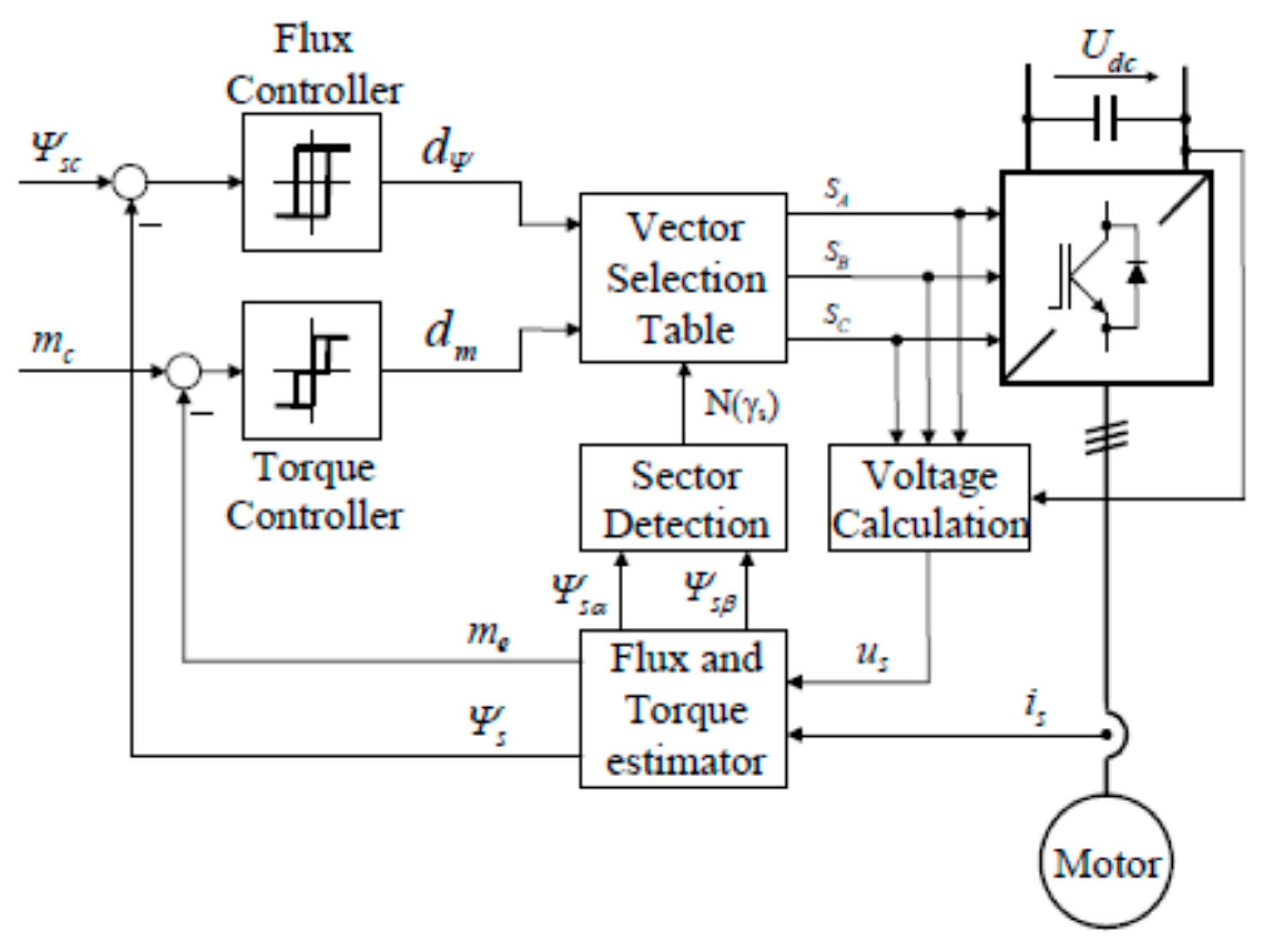
One of the common methods to control the torque (and thus finally the speed) of these motor is Direct Torque Control (DTC). The block diagram of the Switching Table based Direct Torque Control (ST-DTC) scheme is shown in
Figure 1 [
4].
The scheme includes two hysteresis controllers. A stator flux controller imposes the time duration of the active voltage vectors, which move the stator flux along the reference trajectory, and the torque controller determines the time duration of the zero voltage vectors, which keep the motor torque in the defined-by-hysteresis tolerance band. Finally, for every sampling time the voltage vector selection block chooses the inverter switching state (SA, SB, SC), which reduces the instantaneous and torque errors.
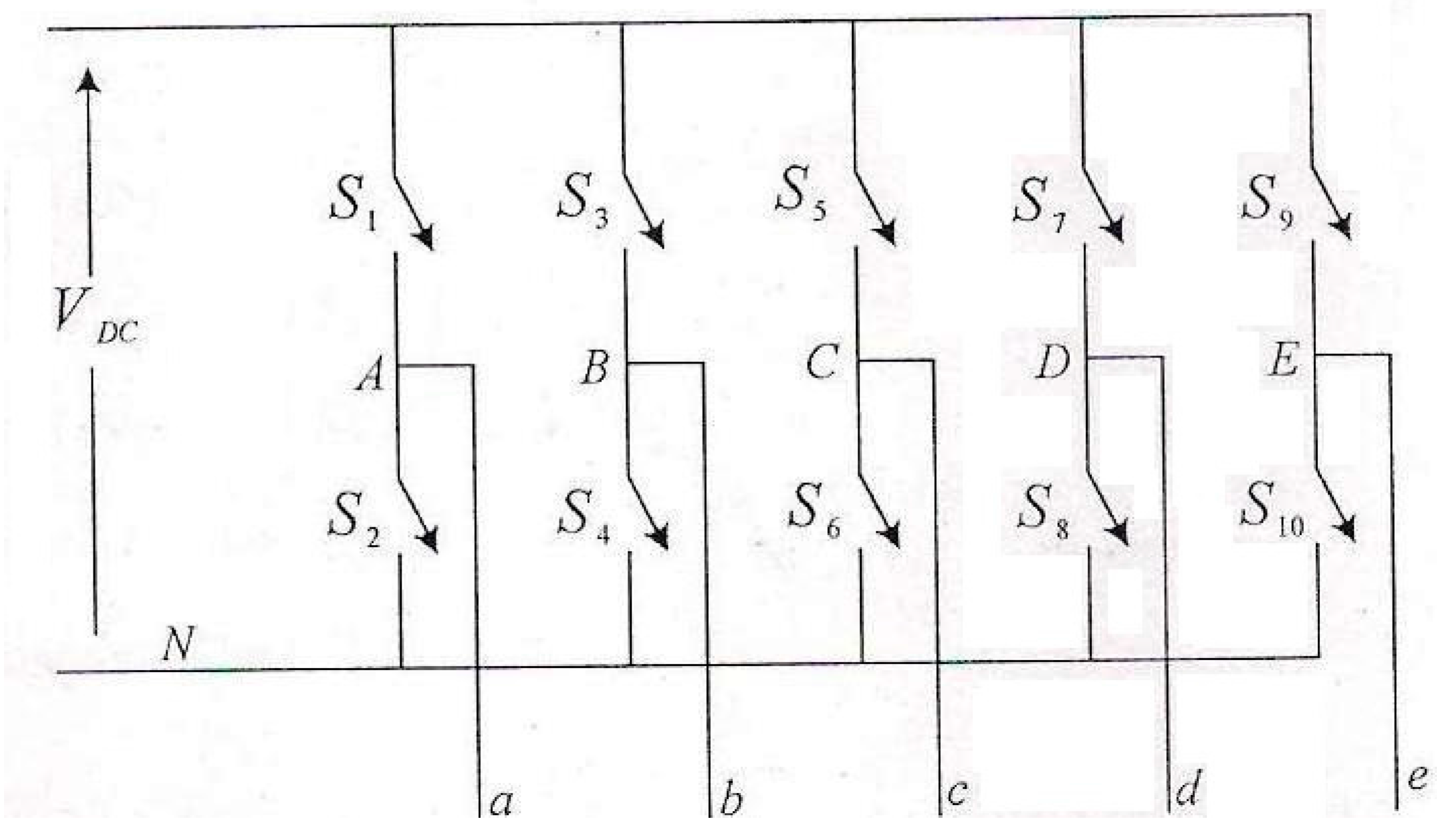
Figure 2 shows the diagram of a five-phase voltage source inverter which is called the classic method of direct torque control in this article.
There are two major drawbacks to applying inverter: low-frequency voltage harmonics and high torque ripple [
5,
6,
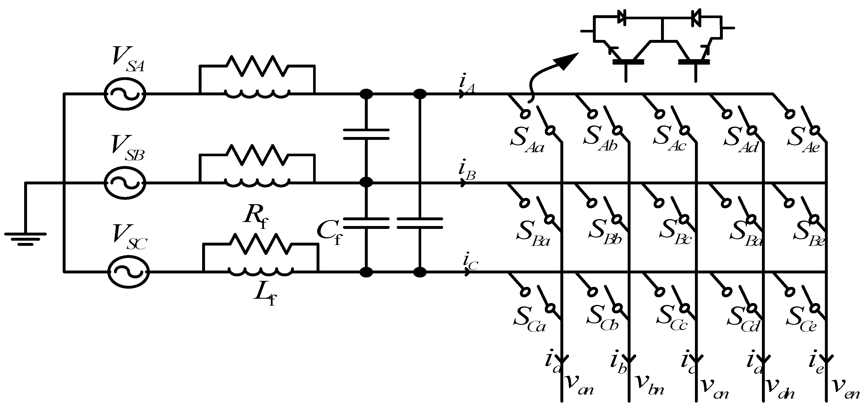
7]. To eliminate these problems, the direct torque control method with a three-phase to five-phase matrix converter (
Figure 3) is introduced [
8,
9,
10]. This circuit is an AC to AC converter. Compared to the VSI converter, intermediate circuits and DC link have been removed [
11,
12].
Using more degrees of freedom in this converter, an optimal switching table is provided, along with the elimination of the mentioned problem, the input power factor is also controlled.
Because the input voltages of the matrix converter are directly supplied by the input voltage source, one of the factors that makes such converters inefficient is the voltage imbalance in the three-phase input supply [
13]. In a three-phase system, voltage imbalance usually takes place when the magnitudes or the phase angles of the line voltages are different from the balanced conditions. The voltage imbalance decreases the motor performance. It can also cause current imbalance which is more intense than voltage imbalance. Unbalanced currents lead to torque pulsation and increase losses. Therefore, the power quality and energy efficiency will be reduced [
14].
Common causes of voltage imbalance are the faulty operation of the power factor correction equipment, unbalanced or unstable utility supply, unevenly distributed single-phase loads on the same power system, and unidentified single-phase to ground faults.
Because such matrix converters are generally applied where the accurate control of the speed and torque of a motor is considered, developing a new method to eliminate the imbalance impact on process performance is necessary. This paper proposes a direct power control technique to solve this problem. First, the motor power and torque equations are developed and the oscillator phrases which come into existence by voltage imbalance are separated. Then, using an active and reactive power reference generator, the controller power reference is changed so that the machine electromagnetic torque remains constant.
It means that the active and reactive power produced by the generator should properly follow the active and reactive power reference which is favorable. In this way, in addition to optimal speed control, torque oscillator parameters will also be eliminated.
2. Modeling of Five-Phase PMSM and Matrix Converter
The five-phase PMSM stator voltage equation can be expressed as follows:
where
Rs is the stator resistance matrix,
is the air gap flux,
Lss is the stator inductance matrix including self-inductance and mutual inductance, and
is the linkage flux matrix which is generated by the permanent magnet and can be expressed as follows:
where
is the value of the permanent magnet flux and
is the rotor position.
For the transfer of the components of a five-phase system from (abcde) space to perpendicular
and
spaces [
15], namely
, the following equations are used:
In the above equations,
. Incorporating Equations (3) and (4) into Equation (1), stator voltages can be expressed as follows:
where
,
,
, and
are
q,
d,
, and
axes of voltage of the stator,
,
,
, and
are
q,
d,
, and
axes of current of the stator,
is angular velocity, and
,
,
, and
are
q,
d,
, and
axes of flux linkage of the stator. They can be expressed as follows:
where
and
are the inductance of
q and
d axes, respectively, and
Lls is leakage inductance of the stator. The electromagnetic torque can be obtained as follows:
where
is the mechanical angle of the rotor and
is the co-energy. Regardless of other formulas, the final equation for torque is obtained as follows:
In Equation (8), p is the pole pair number. According to the above equation, in a five-phase permanent magnet synchronous motor, only the basic components of the subspace influence the production of the electromagnetic torque. Thus, in the driver system of this motor, voltage space vectors of this subspace are selected. It should be noted that when a voltage vector of subspace is chosen, its corresponding vector in the subspace will be also stimulated simultaneously.
Having this information, it is possible to easily simulate a five-phase PMSM.
In the next step, the modeling of a five-phase matrix converter will be discussed. The circuit topology of a three-phase to five-phase matrix converter is shown in
Figure 3. As can be seen, this converter has five bases; every base has three two-way switches. Each switching function is defined as follows:
where
J and
k are the input and output phases, respectively.
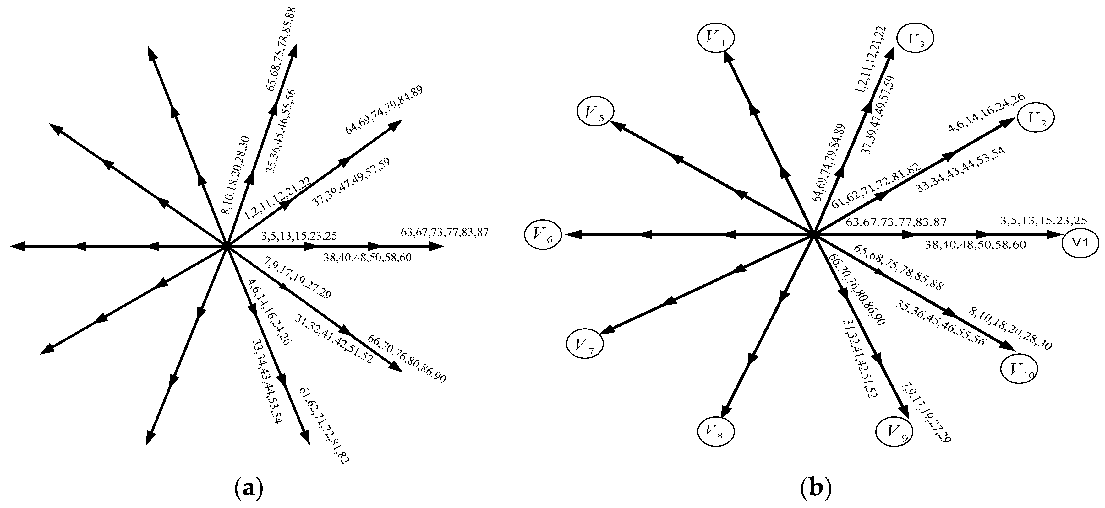
The converter output voltage vectors in the
and
subspaces can be obtained by:
where
is the size of the output voltage vector and
is the phase angle. Generally, there are
switching states in the matrix converter; however, only 93 voltage vectors consisting of three zero vectors and 90 active vectors which have constant directions can be used. Like the five-phase voltage source inverter (VSI), these 90 vectors form ten concentric regular polygons which are divided into large, medium, and small sizes.
Figure 4 shows the voltage vectors in the
and
subspaces. The numbers shown in this figure correspond to the switching status.
3. DTC Method Using a Matrix Converter
The principle of the direct torque control method using a matrix converter is similar to the classic method of direct torque control (using voltage source inverter).
First, the classic direct torque control is done and the inverter output voltage vectors are determined. These vectors are called virtual voltage vectors (vectors
through
inside the small circle are shown in
Figure 4. Then, it must be determined which vectors of the matrix converter can be replaced by the inverter virtual vector. In general, there are six matrix converter voltage vectors for each virtual voltage vector. For example, the vector
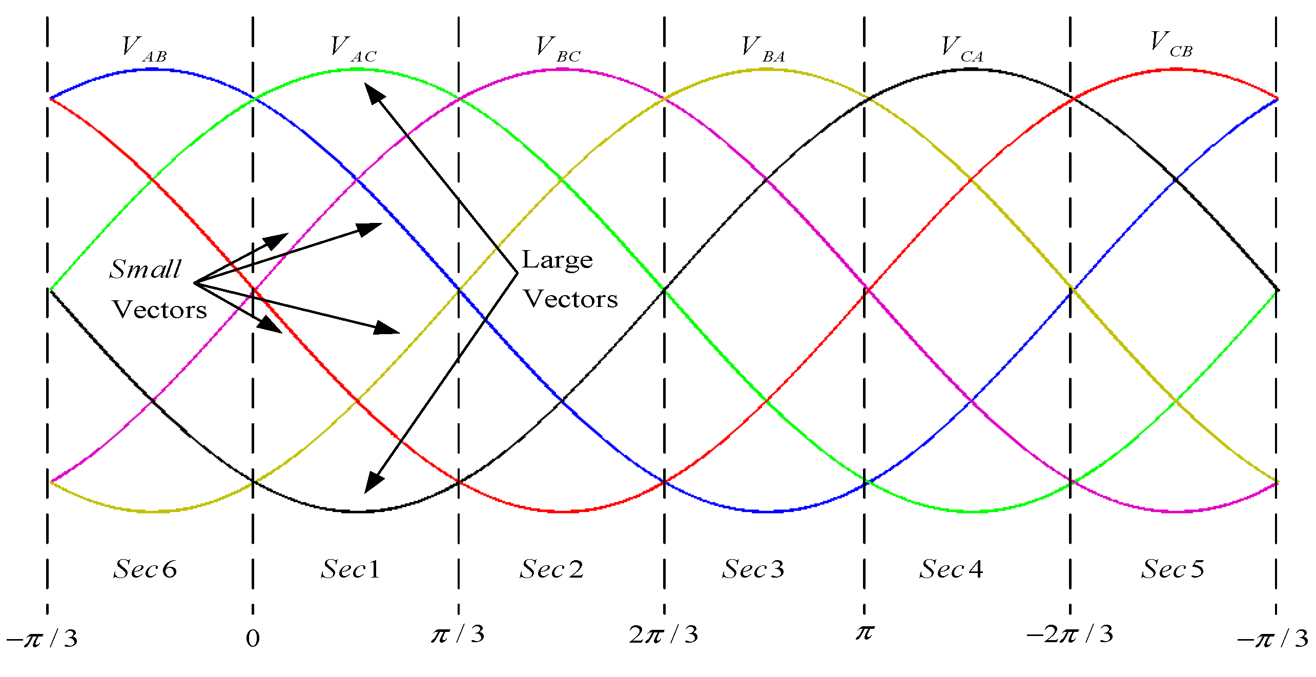
means vectors 3, 5, 13, 15, 23, and 25 from the switching status. The next step is to study where the phase-to-ground voltage vectors are located, in which sector of the six vector space.
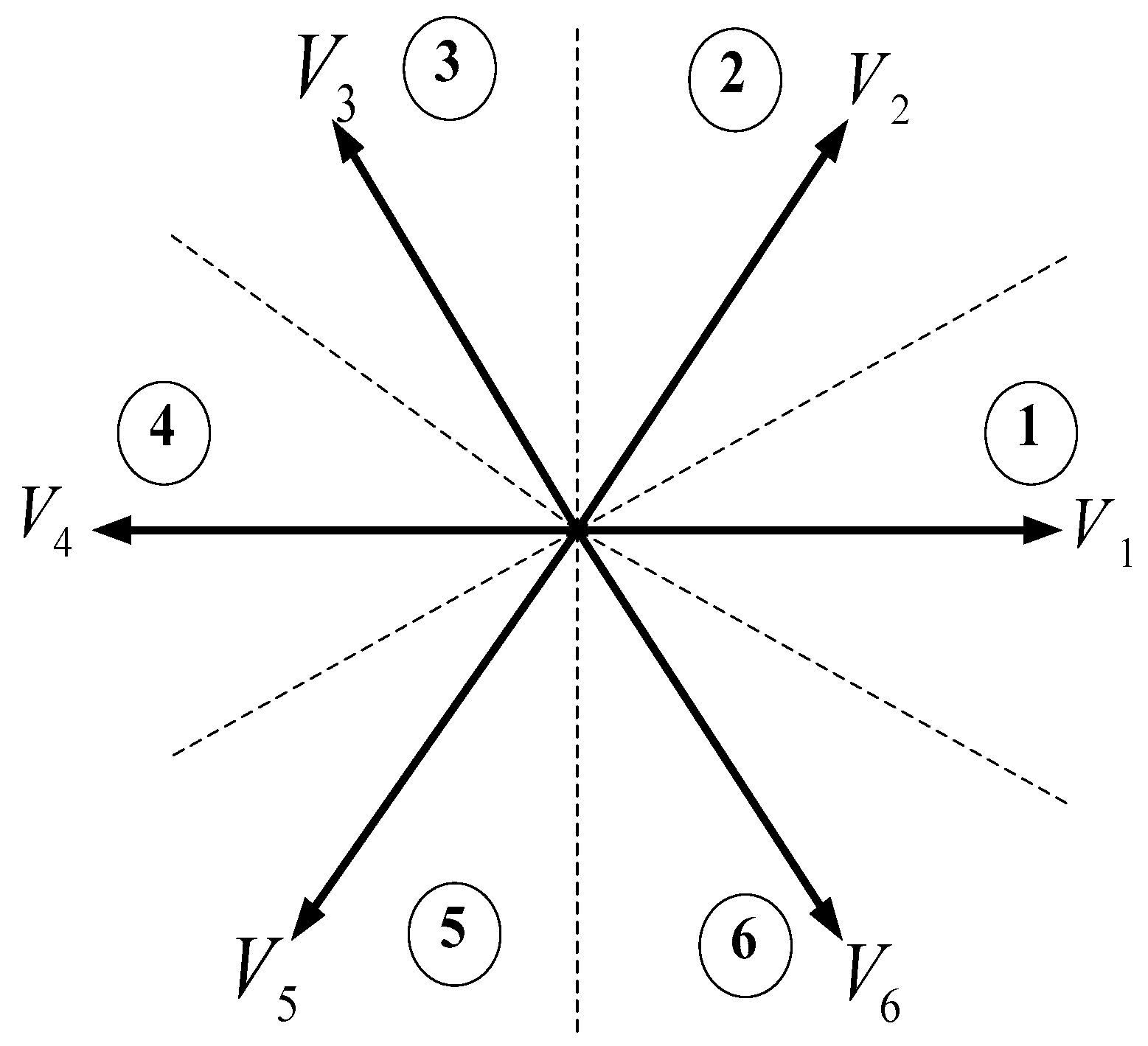
Figure 5 shows the path of the input voltage of a three-phase to a five-phase converter. Knowing the input voltage vector section, and according to
Figure 5, the path is divided into six sectors, the first of which starts from
.
In this case, there will be six voltage vectors in every sector which do not change their sign in the sector, and thus can be used in the direct torque control method. From among the six vectors, four vectors are small and two vectors are large. Three voltage vectors (two small vectors and one large vector) can be used in each sector as shown in
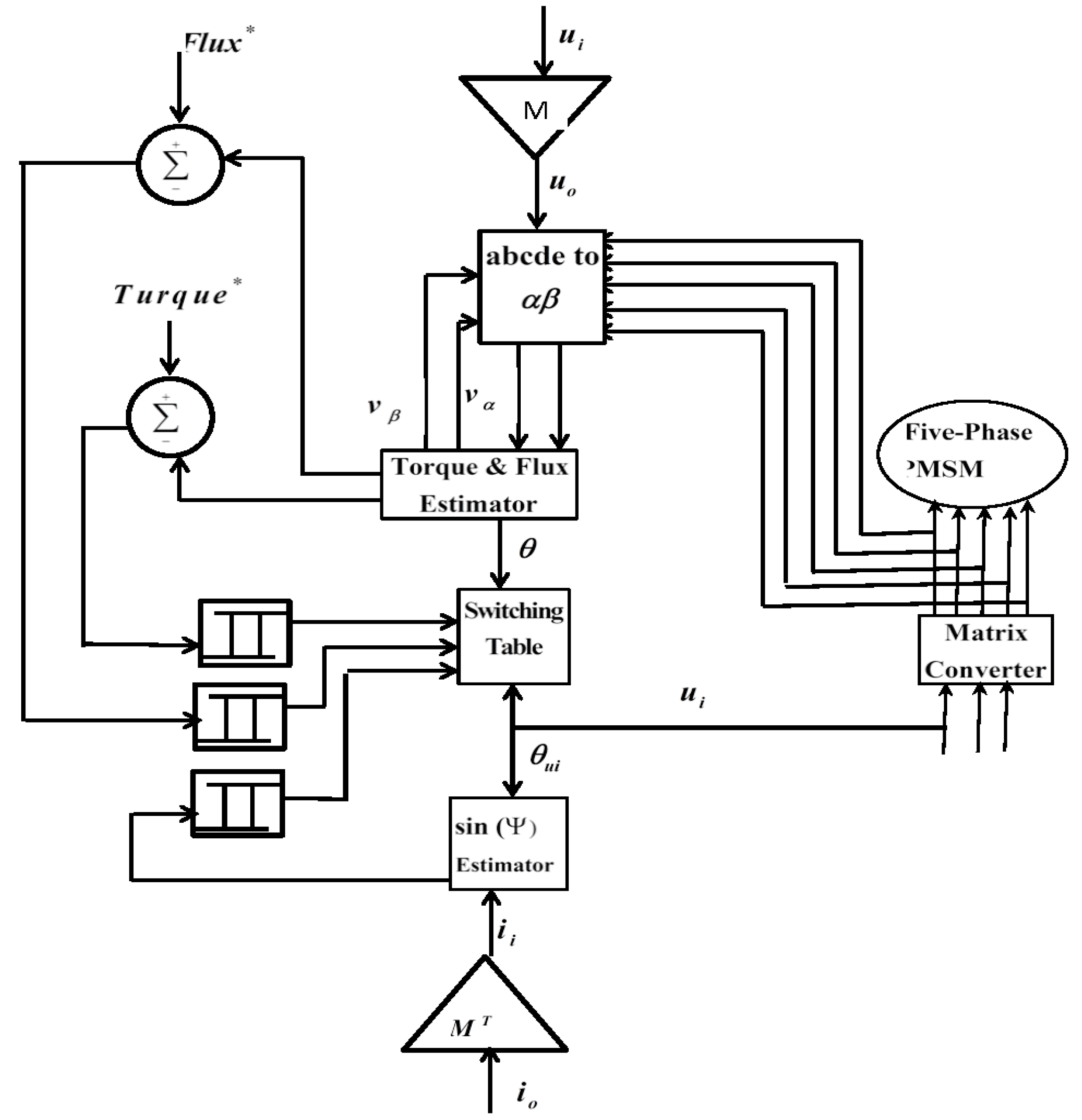
Figure 5. It can be concluded that compared to classical direct torque control in which only one voltage vector is produced in each sampling cycle, the matrix converter can deliver three voltage vectors. These vectors have the same effect on increasing or decreasing the flux and torque. Therefore, the matrix converter has two more degrees of freedom than the voltage source inverter, which is used to control other parameters of the machine such as power factor and line current THD, therefore, reducing high flux and torque ripples. According to the above statement, a switching table is provided for the direct torque control of the five-phase PMSM, which can be seen as a part of the block diagram of the DTC method using a matrix converter, as shown in
Figure 6 [
16].
4. Five-Phase PMSM Control in Terms of Unbalanced Supply Voltage
4.1. Direct Power Control of a Five-Phase PMSM
In the rotor reference frame of PMSM, the voltage of the stator equation can be expressed as follows [
17]:
where
,
, and
represent the stator voltage, resistance, and flux, respectively.
The stator flux linkage vector in the rotor reference frame is expressed as follows:
where
is the self-inductance of the stator.
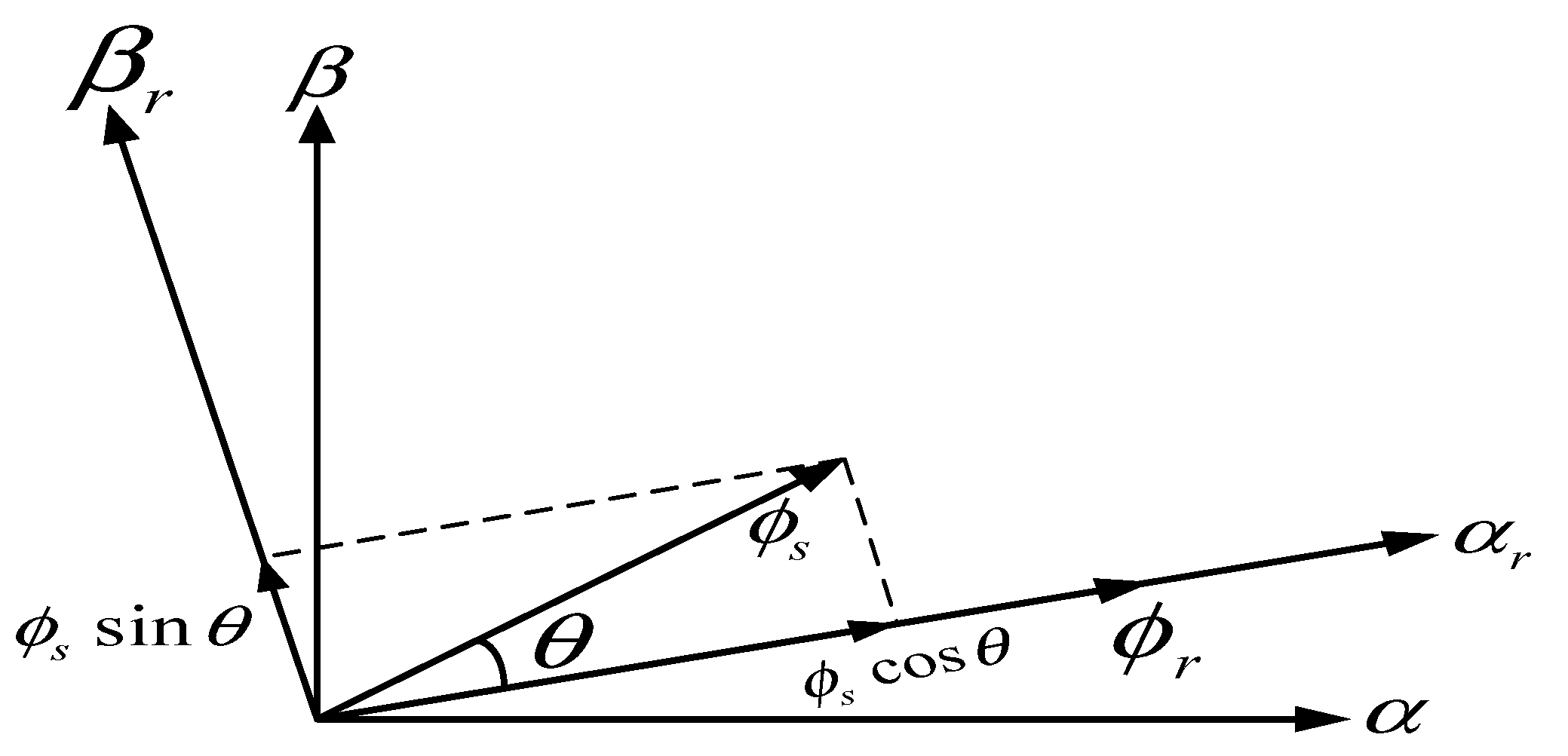
The relationship between the rotor flux and stator flux in the stationary reference system
and the rotor reference system
is shown in
Figure 7.
The stator flux in the
reference frame is expressed as follows:
where
is the angle of the stator flux in the rotor reference frame, as well as the angle between the stator flux and the rotor flux.
The stator active power Equation is as follows [
18]:
Substituting Equation (11) in Equation (14), and regardless of the stator resistance,
can be expressed as follows:
where
is the angular frequency of the rotor.
By deriving Equation (13), Equation (16) can be obtained:
Referring to
Figure 7, the following Equation is obtained:
where
is the stator’s angular frequency.
Substituting Equation (17) in Equation (16):
On the other hand, the stator current in the rotor frame can be calculated using the following Equation:
Using the equations obtained above, the active power Equation can be written as follows:
By deriving Equation (19), active power changes are obtained as follows:
Similarly, reactive power is obtained from the following Equation [
19]:
Incorporating equations, Equation (23) is expressed as follows:
As a result, the reactive power Equation can be written as follows:
and similar to Equation (21), the reactive power changes are obtained as follows:
According to Equations (21) and (25), rapid changes of active and reactive power can be made by changes in
and
respectively. It can be seen from
Figure 7 that
and
are the components of the stator flux
, perpendicular to the rotor flux, and in the direction of the rotor flux, respectively. This shows that, if the stator flux variation is in the direction of the rotor flux, namely
, reactive power
changes. Similarly, if the stator flux variation is perpendicular to the rotor flux, namely
, active power
changes.
4.2. Investigating the Effect of Two-Level Inverter Voltage Vectors on Active and Reactive Power Changes
To study the effect of voltage vectors, the vector space of voltages of a two-level inverter is divided into six sectors, each sector covers 60 degrees [
20]. This is illustrated in
Figure 8.
In reference [
21], the effect of voltage vectors on active and reactive power changes was investigated.
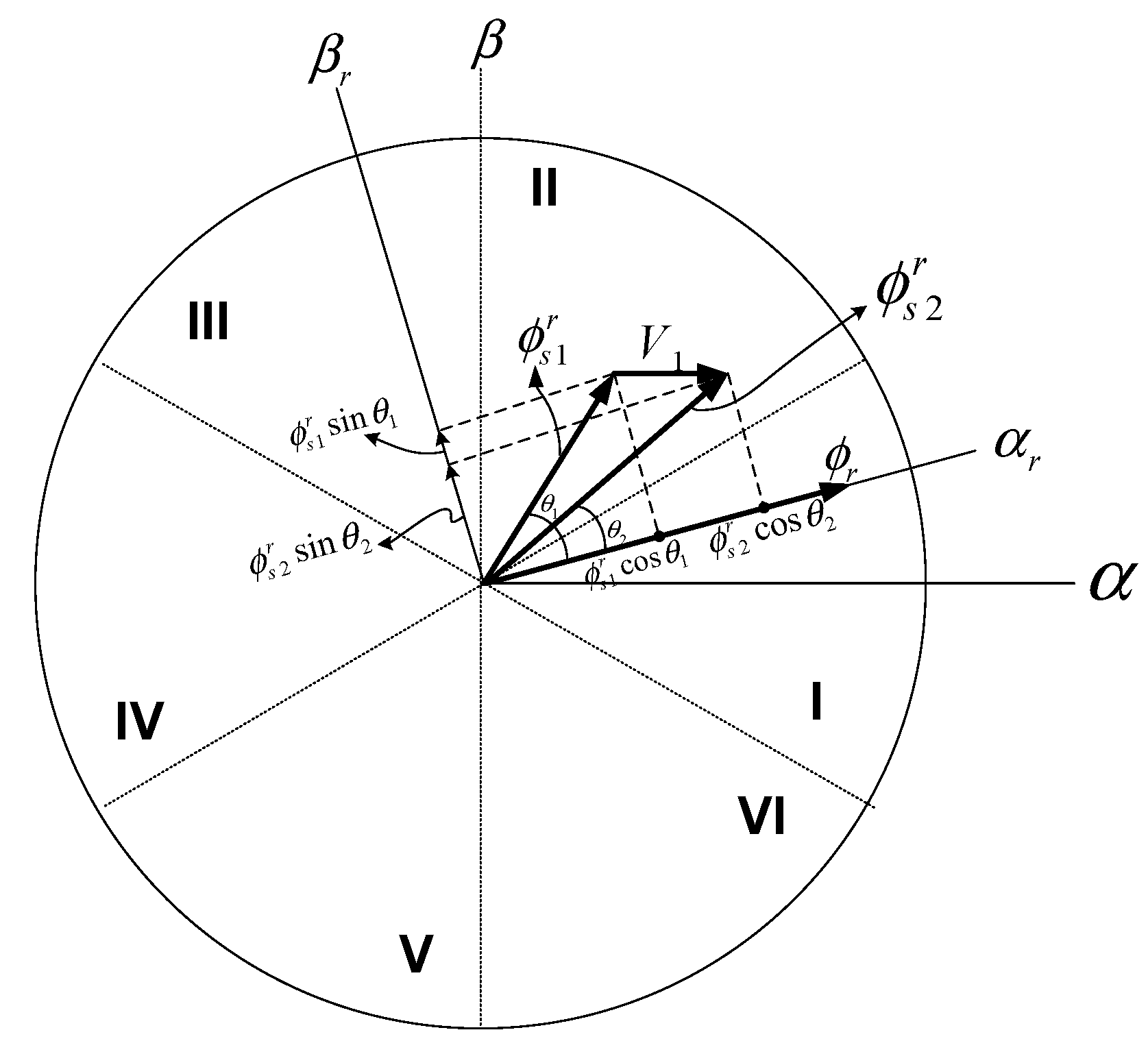
According to
Figure 9, suppose that the stator flux vector in the reference frame of the rotor (
) is located in the second section of the vector space. As shown in this figure, this vector leads the rotor flux vector by
degrees. Now, if the voltage vector
is applied to the converter, the position of the stator flux vector is changed and moved to
. It can be seen that by applying the voltage vector
to the converter, the value of
decreases and the value of
increases. As a result, with respect to the Equations (21) and (25), the active and reactive power increases.
In the same way, knowing the position of the stator flux in the rotor reference frame, the effect of all voltage vectors on active and reactive power changes can be studied. According to the example, a switching table can be prepared and used for different modes.
4.3. Vector Space under Imbalance Conditions
In this section, an imbalance caused by an unbalanced load is studied. An asymmetric five-phase system can be decomposed into five symmetrical systems of five phases. These five systems are called the sequence of zero, positive sequence
subspace, negative sequence
subspace, positive sequence
subspace, and negative sequence
subspace. They can be obtained by,
where
. Parameters
xa,
xb,
xc,
xd, and
represent the unbalanced system. Parameters
,
, and
represent zero, positive, and negative sequence components, respectively. It is assumed that the five-phase system being studied is a five-wire five-phase system. This means that the system does not have a neutral wire. In this case, the sum of the five-phase currents is always equal to zero
. As a result, the zero sequence current component would be equal to zero. Consequently, the components of the zero sequence voltage are zero
.
Therefore, to take into account the positive and negative sequence, the voltage and current vectors can be expressed as follows:
Thus, two space vector of the five-phase system can be expressed as follows:
A five-phase unbalanced system can be demonstrated as the sum of positive and negative sequences as follows:
An unbalanced five-phase system can be represented as the sum of two positive and negative sequence vectors that rotate in the opposite direction with the same frequency as follows:
4.4. Direct Power Control
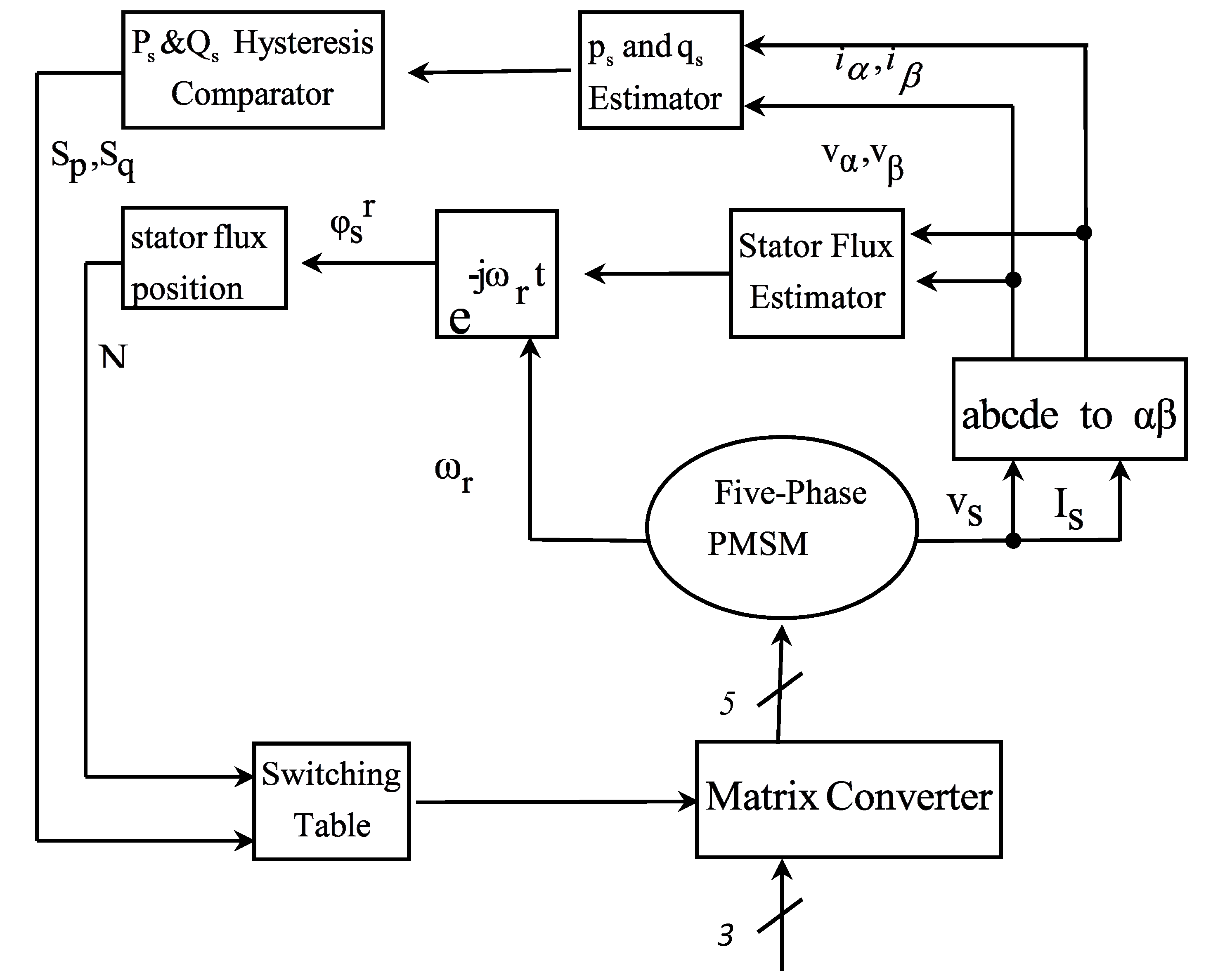
Figure 10 shows a block diagram of the direct power control method of a five-phase PMSM.
It can be seen from the figure that the voltage and current are sampled from the stator and transmitted to the stationary reference frame. Then, using these voltages and currents, active and reactive powers can be calculated. Moreover, the size of the stator flux and its angle are obtained using the following Equation [
22]:
The stator flux obtained from the synchronous reference frame is transmitted to the rotor reference frame and
is calculated. Then, according to the angle of the flux, the region where the flux vector is located is obtained (with N as shown in
Figure 10). In general, the purpose of the direct power control method is that the active and reactive power of the motor properly follow the favorable active and reactive power references. In order to achieve this, the estimated power values are compared with the reference values, and their differences are transmitted to two three-level hysteresis comparators, which are described below.
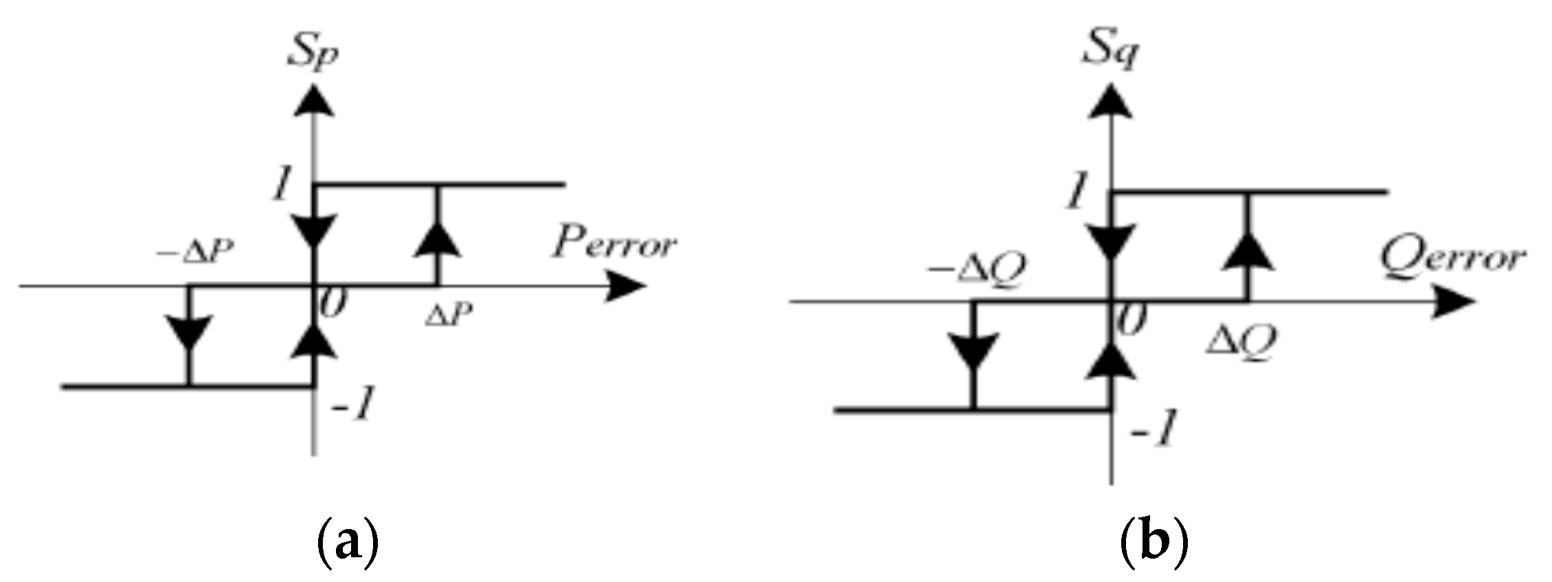
4.5. Three-Level Hysteresis Comparators
To determine the status of active and reactive power, the three-level hysteresis comparators are used as shown in
Figure 11.
The difference between the actual value of the power and the reference value is expressed by:
In this equation, the reference values of the active and reactive power are shown by and , respectively.
These error values are sent to the comparators and, according to the allowable band of error, they produce suitable active and reactive power shown as and , respectively.
If this difference is greater than the permitted error value that is interpreted as the allowed band, the comparator output sends the digital number (1), and if the error is in its allowed band, the comparator output sends the digital number (0).
Also, if the error is less than the allowed band, the comparator output sends the digital number (−1).
4.6. Analysis of Five-Phase PMSM under Imbalance Conditions
The five-phase PMSM stator voltage equation was given in Equation (1). From Equations (1) and (8), the torque equation can also be expressed as follows:
where
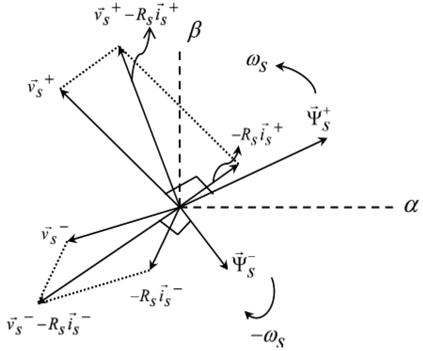
is the derivative operator and “*” sign represents the conjugate of each complex vector. When the stator voltage is unbalanced, all vectors in Equation (1) have a positive and negative sequence. Firstly, the effect of unbalanced voltages on the stator flux is studied. From Equations (1) and (27), the relationship between the stator flux and voltage can be expressed as follows:
As can be seen from
Figure 12, the stator flux includes two sets of positive and negative components that rotate in opposite directions.
Substituting the components of the positive and negative sequence of the stator flux and current in Equation (32), the following equation is obtained:
It can be seen that the electromagnetic torque consists of two constant phrases (phrases that are the product of identical sequences) and two phrases at speed (phrases that are the product of different sequences).
Thus, substituting Equation (33) in Equation (34), the following Equation is obtained:
Equation (35) can be expressed as follows:
which
,
,
,
, and
are:
The relationship between active and reactive power can be expanded as follows:
The active power equation extracted from Equation (38) can be expressed as follows:
which
,
,
, and
are:
Similarly, the reactive power Equation can be expressed as follows:
which
,
,
, and
are:
As can be seen from Equation (37), and are oscillating factors in the electromagnetic torque, since they include voltage and current components with two different sequences.
Similarly, according to Equations (40) and (41), , , and cause fluctuations in the active and reactive power, respectively.
Meanwhile, according to Equations (37) and (40), it can be seen that and .
As a result, the oscillating factors of the active power and the electromagnetic torque are similar.
In the following, it is first studied whether the electromagnetic torque fluctuations will be eliminated by eliminating the active and reactive power oscillators. Otherwise, because the priority is to eliminate the electromagnetic torque fluctuations, the conditions to eliminate the oscillator of the electromagnetic torque are applied and under these conditions, new references for active and reactive powers will be obtained.
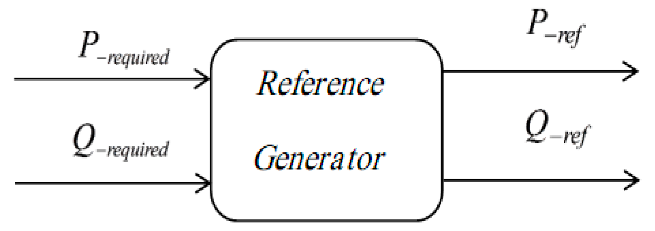
4.7. Remove Power Oscillator Factor
According to
Figure 13, and as previously mentioned, a reference value is considered to control the power. The controller must act so that the stator powers properly follow the reference power. Because there is an imbalance in the source voltage, the controller must adjust the source reference so that it creates a new reference power. In
Figure 13, the primary reference power (before an imbalance) is shown as (
) and the new reference power (after an imbalance) is shown as
.
It can be seen from Equation (39) that for the production of constant active power, the sum of two oscillator factors (
) must be zero as follows:
Also based on Equation (41), for the production of constant reactive power, the sum of two oscillator factors (
) must be zero as follows:
Since each of the values , , , and is dependent on the positive and negative sequence components, none of them can be zero by itself. In that case, the stator current should be zero, which is not desirable. Therefore, only their sum can be zero. ( and ).
In this condition the reference powers before and after an imbalance will also be equal as follows:
The torque equation can also be obtained as follows:
As can be seen from Equation (45), torque oscillator factors are still present, which is not desirable.
It should be noted that the main goal is to obtain a constant torque in imbalance conditions, not constant power.
4.8. Remove Torque Oscillator Factor
According to Equation (36), the only way to eliminate the torque oscillator factors is obtained under the following conditions:
As a result, the electromagnetic torque value can be obtained as follows:
In this condition, the relationship between reference powers before and after an imbalance condition is as follows:
Based on Equations (50) and (51), the controller should operate so that the motor powers properly follow the new reference powers and the motor is used in constant torque and consequently in constant speed.
5. Simulation Results
In this section, the speed control of a matrix converter-fed five-phase PMSM under an unbalanced input voltage, which is improved with the proposed method in this paper, is simulated using Matlab/Simulink software. The steady-state and dynamic performance of the motor is studied. The results are compared with those of a three-phase supply input voltage unbalanced network without correction. The motor’s parameter is shown in
Table 1.
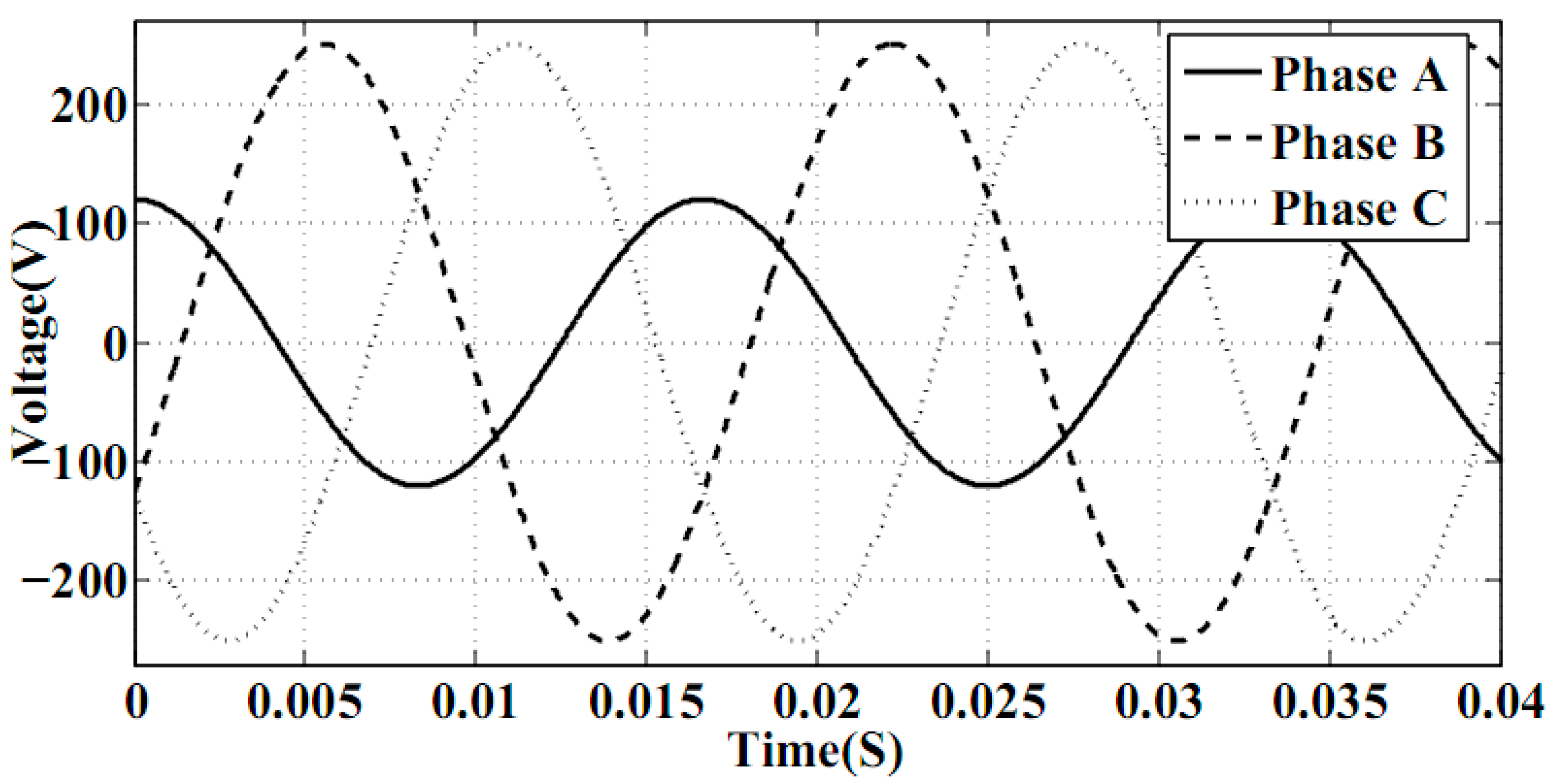
An unbalanced three-phase voltage source can be created in different states, such as differences in amplitude, phase, frequency, and/or all of them.
Figure 14 illustrates an unbalanced three-phase source whose amplitude of phase “A” is different from other phases.
Other characteristics of the source (phase and frequency) are the same as a normal three-phase power supply. This happens when the phase area is loaded by separate single phased appliances connected to a typical three-phase input. Also a short part of the time (0.04 s) is selected.
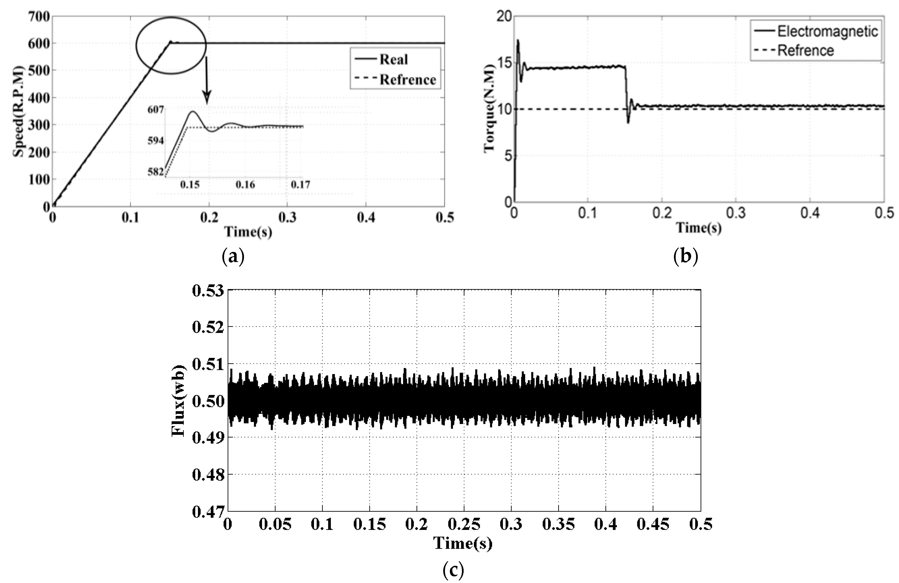
Figure 15 illustrates the simulation results with the proposed method under the above-mentioned conditions.
As shown in
Figure 15a, the motor speed will follow its reference value properly. The reference speed value is 600 R.P.M. and the results are shown in
Table 2.
Figure 15b shows the load torque in comparison with the electromagnetic torque. The load torque value is 10 N.M. The information obtained from simulation is shown in
Table 3.
Figure 15c demonstrates the stator flux diagram on the
axes of stationary frame. It should be noted that the reference flux is equal to the motor permanent magnet flux and is considered to be 0.5 (wb). This figure shows that the stator flux will follow its reference value properly. The information was obtained from simulation is shown in
Table 4.
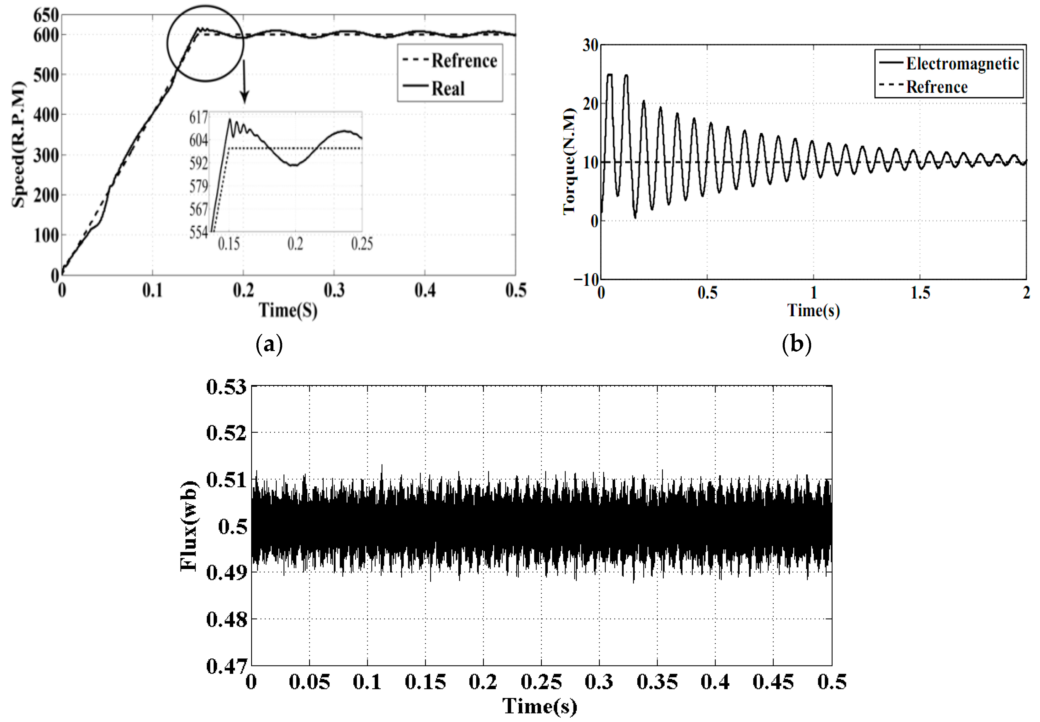
Figure 16 shows the same characters of the motor as in
Figure 15 under the same input conditions, but without using the imbalance correction method.
Figure 16a illustrates the motor speed without using the correction method. The information obtained from simulation is shown in
Table 5.
As shown in
Table 5, a lot of the motor speed characteristics as settling time, settling max, overshoot and peak value are more than
Figure 15a.
Figure 16b shows the load torque in comparison with the electromagnetic torque without using the correction method. The information obtained from simulation is shown in
Table 6.
As shown in
Table 5, also a lot of motor torque characteristics as settling time, settling max, overshoot and peak value are more than
Figure 15b.
Figure 16c demonstrates the stator flux diagram on the
axes of the stationary frame without using the correction method. The information obtained from simulation is shown in
Table 7.
According to
Table 7, the overshoot of motor flux is increased and there is a worse situation than previously.
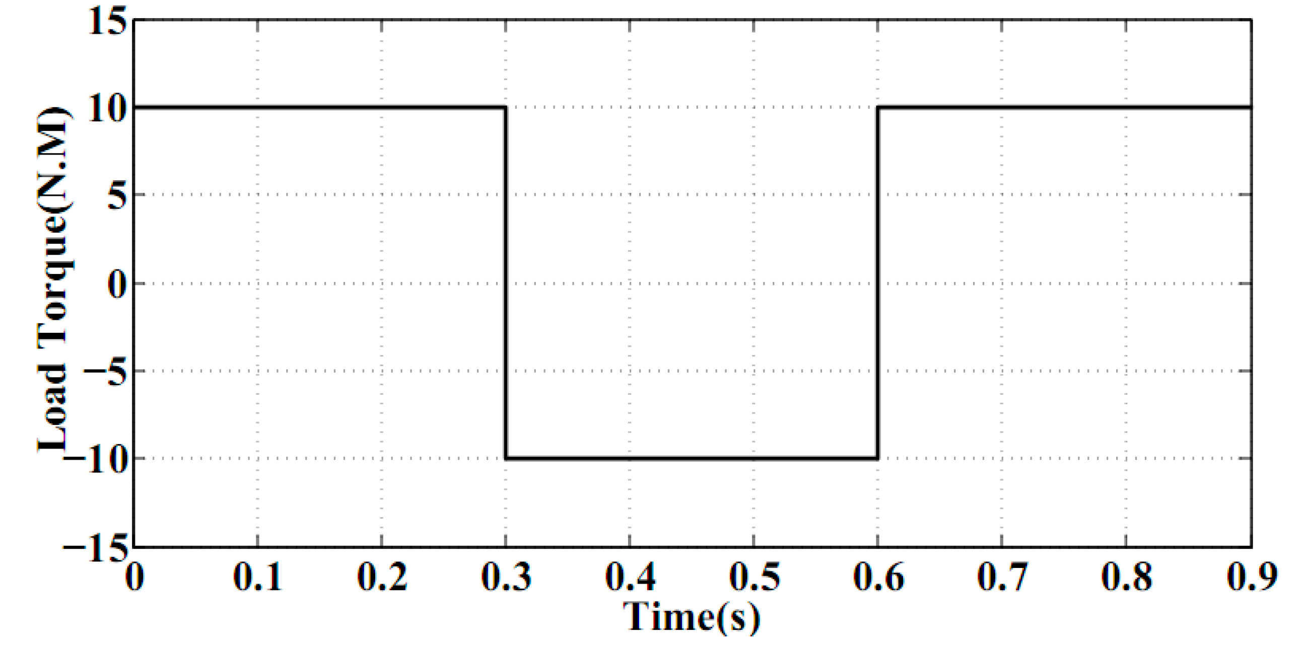
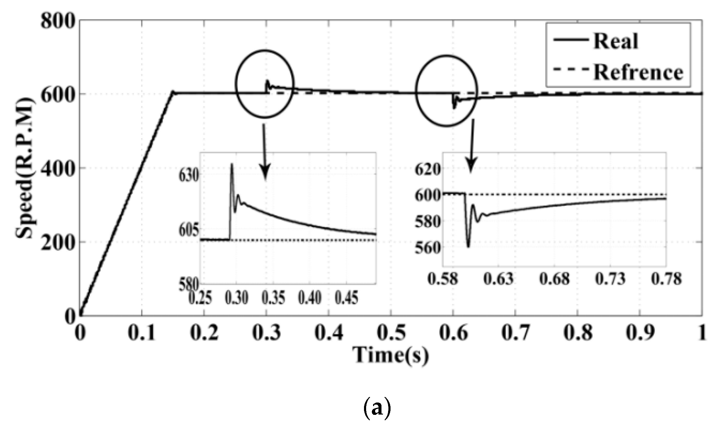
To evaluate the motor performance with the proposed method in dynamic conditions, a step load at the reference speed of 600 (RPM) is applied to the motor (
Figure 17).
According to this figure, the torque load direction was changed between 0.3 to 0.6 s.
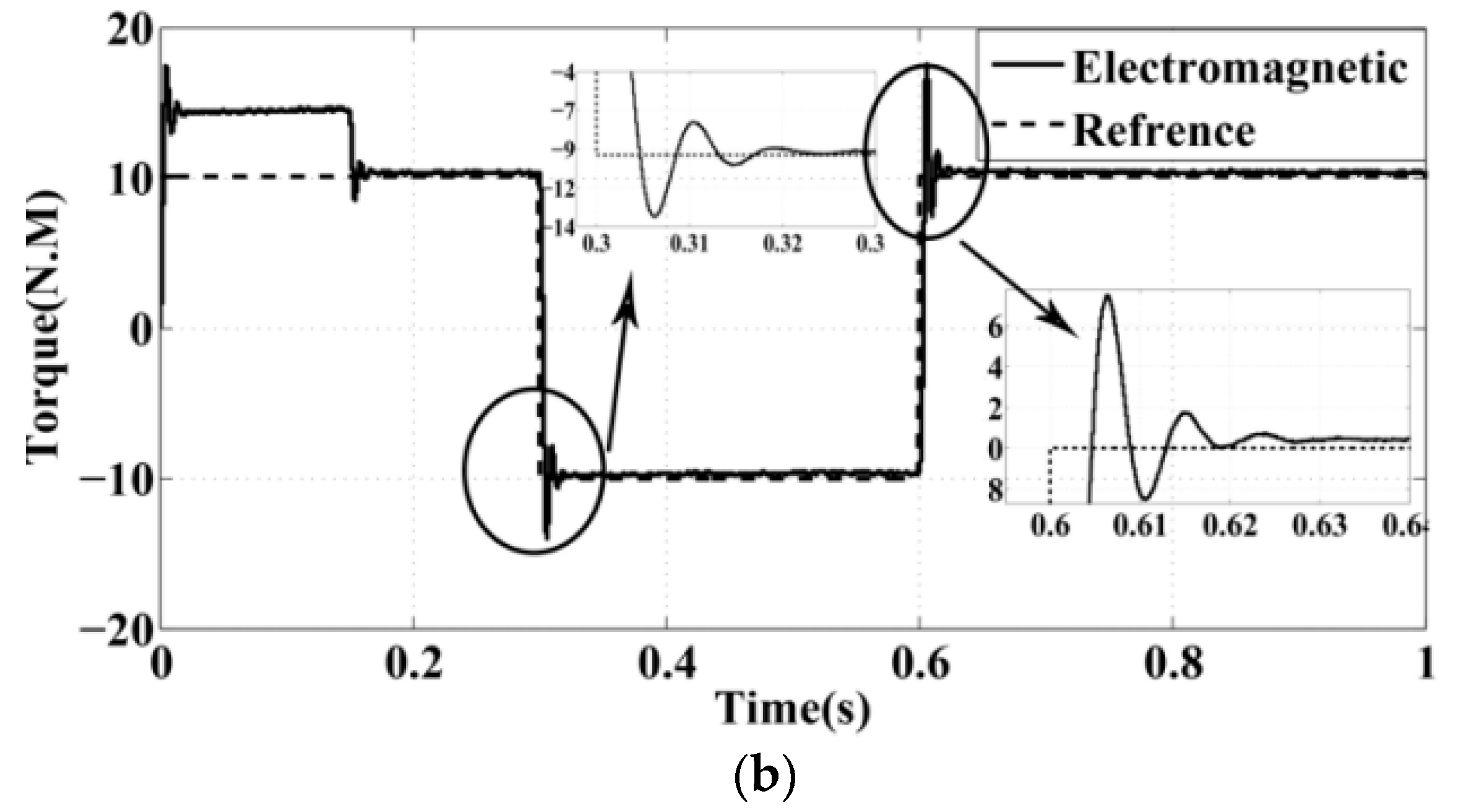
Figure 18 illustrates the motor characteristics.
As shown in
Figure 18a, the motor speed follows its reference value properly. The reference speed value is 600 R.P.M. the information obtained from simulation is shown in
Table 8.
Figure 18b shows the load torque in comparison with the electromagnetic torque. The load torque value is 10 N.M. the information obtained from simulation is shown in
Table 9.
6. Conclusions
In this paper, a new technique is proposed to eliminate the unbalanced three-phase voltage source effect on a five-phase permanent magnet motor performance that uses a matrix converter in its driver structure. This method is based on direct power control. Because of the imbalance in the voltage source, the motor torque and speed will fluctuate. By identifying the torque oscillation factors and by eliminating these factors, the motor power reference changes. A reference generator has the task of generating a new power reference every time. With a control unit, the active and reactive powers of the motor properly follow the new active and reactive power references. Each time the reference power changes, however, the torque and speed characteristics remain constant.


