1. Introduction
In the literature, several types of Synchronous alternating current (AC) machines can be found, e.g., Interior and Surface Permanent Magnet Motors (IPMs and SPMs) and Synchronous Reluctance Motors (SynRMs) [
1,
2,
3,
4,
5]. Thanks to their high efficiency, synchronous machines have received great interest in several applications, e.g., electric vehicles and photovoltaic (PV) pumping systems [
3,
4,
5]. Recently, more research focus has been given to the SynRMs. This is thanks to their low cost and high efficiency compared to induction machines. In addition, a rotor of several flux-barriers per pole is always employed that has a simple and a rugged structure. The rotor losses are low, and hence it can work properly at higher temperatures [
6,
7,
8]. However, SynRMs have two main disadvantages: the high torque ripple and the low power factor [
3,
4,
5,
6,
7,
8]. On the one hand, the high torque ripple can be reduced by two main approaches: selecting optimal geometrical parameters for the rotor flux-barriers (in particular, the flux-barrier angles) and skewing the rotor with respect to the stator [
3,
6]. These two methods can be combined together, resulting in a SynRM design with a torque ripple of less than 10% [
3]. On the other hand, the rather poor power factor of SynRMs requires a high kVA inverter. This means that the low cost of SynRM may be compensated for by a higher cost inverter [
3,
8]. In order to improve the power factor and to enhance the torque density and efficiency of SynRMs, permanent magnets (PMs) are inserted into the rotor flux-barriers, resulting in a PM-assisted SynRM (PMaSynRM) [
9]. Ferrite PMs are always employed in a PMaSynRM to reduce the machine’s cost compared to conventional permanent magnets synchronous machines (PMSMs) [
9,
10]. In addition, they can work at higher temperatures compared to PMSMs with rare-earth magnets. This indeed increases the reliability of PMaSynRMs. Moreover, the stator winding configuration can be a possible way to further improve the overall SynRM performance [
11,
12].
In the literature, much research work on SynRMs and PMaSynRMs can be found [
3,
4,
5,
6,
7,
8,
9,
10,
11,
12,
13,
14,
15,
16]. For example, in [
8], SynRM performance is compared for different electrical steel grades. It is shown that the electrical steel grade has an enormous influence on SynRM efficiency: about 9% points higher for NO20 compared to M600-100A. In addition, the output torque increases by about 8%. However, there is a negligible impact on the SynRM’s power factor for different steel grades. In [
9], an experimental investigation on PMaSynRM with ferrite magnets for automotive applications is presented. In addition, the irreversible demagnetization of ferrite magnets and mechanical strength are considered. A dual-phase material is utilized in the SynRM rotor design for traction applications in [
14]. This is done by using a non-magnetic material in the radial and tangential ribs of the flux-barrier, leading to an increased saliency ratio. Eventually, the overall machine performance is improved compared to the conventional rotor design. A design and optimization of a high speed PMaSynRM for traction applications is investigated in [
15]. The study takes into account both highways and city driving cycles. Various experimental tests on SynRM and PMaSynRM are presented in [
16]. It is shown that inserting PMs in the rotor leads to a 10% increase in the SynRM’s torque at low speed and a 50% increase in a field weakening operation. The influence of rotor skewing is studied as well, showing a decrease in the torque ripple to about one third. However, the machine’s torque is slightly decreased. Moreover, it is evident that the SynRM’s power factor is improved in the overall operating regions when PMs are inserted in the rotor. Overlapping fractional slot concentrated windings are applied to a SynRM in [
11]. It is shown that this winding type increases the power density and efficiency. In addition, it increases the robustness and the thermal behaviour of the SynRM. However, several challenges still need to be addressed in the literature for further research for this type of winding, e.g., high torque ripple and iron loss due to high magnetomotive force (MMF) space harmonics. In addition, the power factor is too poor. A combined star–delta winding is applied to a SynRM and compared to the conventional star connection in [
12]. It is found that the SynRM’s output torque increased by about 5% at the rated conditions compared to the conventional star connection. This is because of the improved winding factor of the star–delta connection. In addition, the efficiency of the SynRM was slightly increased with a star–delta connection. However, there is no influence on the power factor using the different windings.
The work presented herein compares the performance of four prototype SynRMs having an identical geometry of iron lamination stacks in the stator and rotor; two rotors (with and without PMs) and two stator winding connections (star and combined star–delta) are considered. The prototype of a combined star–delta winding in the stator and ferrite PMs in the rotor could be a very promising candidate for several industrial applications, e.g., PV pumping applications and electric vehicle traction.
2. Prototype SynRM Design
In this section, the design of four machines with identical geometry but two different rotors and stator winding topologies is given. The optimization of the machines is not the goal of this paper: it is done in [
17,
18] and only briefly presented here.
In this study, a 36 slot and 4 pole SynRM is employed with the geometrical parameters listed in
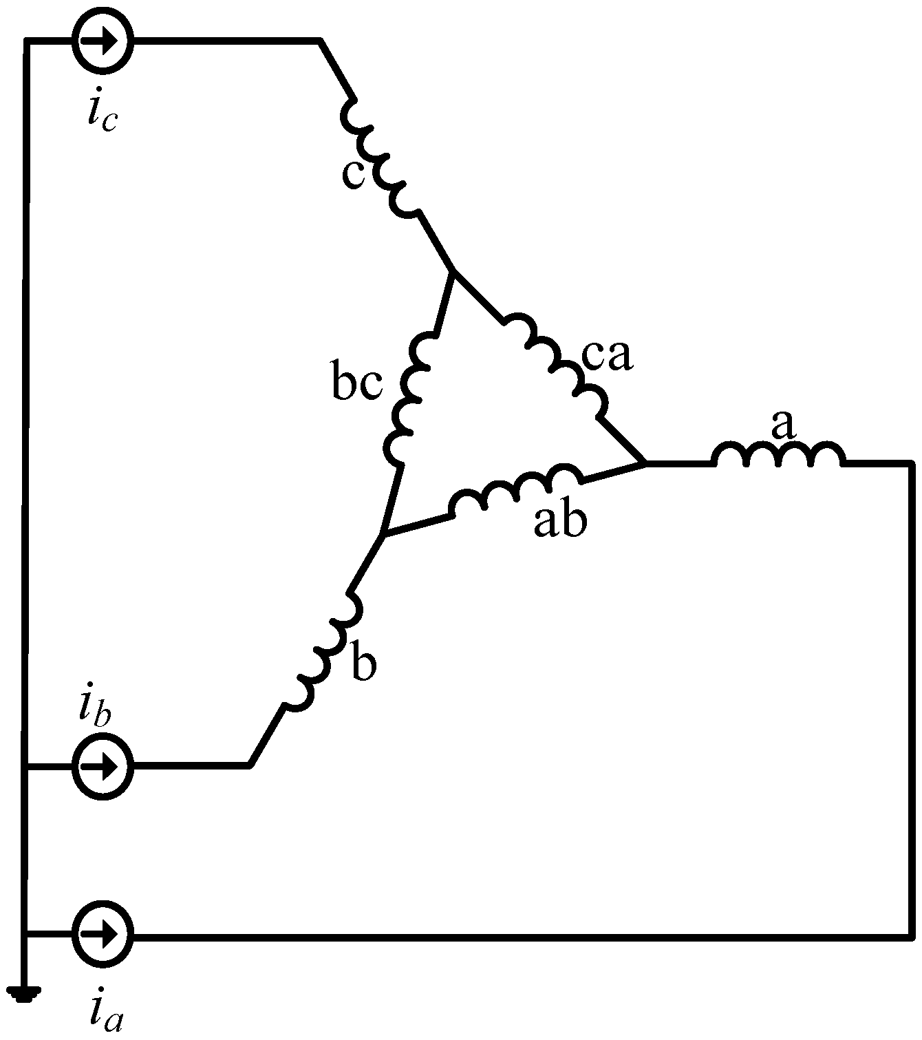
Table 1. Two distributed winding configurations are used: the first configuration is the conventional star-connected winding and the second one is two three-phase winding sets connected in a combined star–delta connection. Both of the winding configurations result in three phases as shown in
Figure 1. This means that the number of stator slots/poles/phases (
q) is 3. The number of turns per slot of the star connection is 26, with a conductor cross-section area of 1.573 mm
2. As shown in the literature [
19,
20,
21], two possible connections of star and delta coils can be made: either the two coils are connected in series or they are connected in parallel. The star–delta parallel connection is not favoured because of some practical difficulties in the number of turns and the cross-section area of the conductors. Eventually, circulating currents may occur, resulting in additional losses. Therefore, the series connection of the star and delta coils is adopted. The wiring connection of the series of star–delta coils is shown in
Figure 1. As
q equals 3, one slot for the star coil and two slots for the delta coils are considered. As the current of the delta coils is lower than the star coil’s current by a factor of
, the number of turns of the delta coils has to be higher than the number of star coil turns by the same factor. This is to generate approximately the same MMF with the two coils. Consequently, the number of turns of the delta coils is 45 turn/slot. The cross-section area of the delta coils must be lower than the star coil by a factor
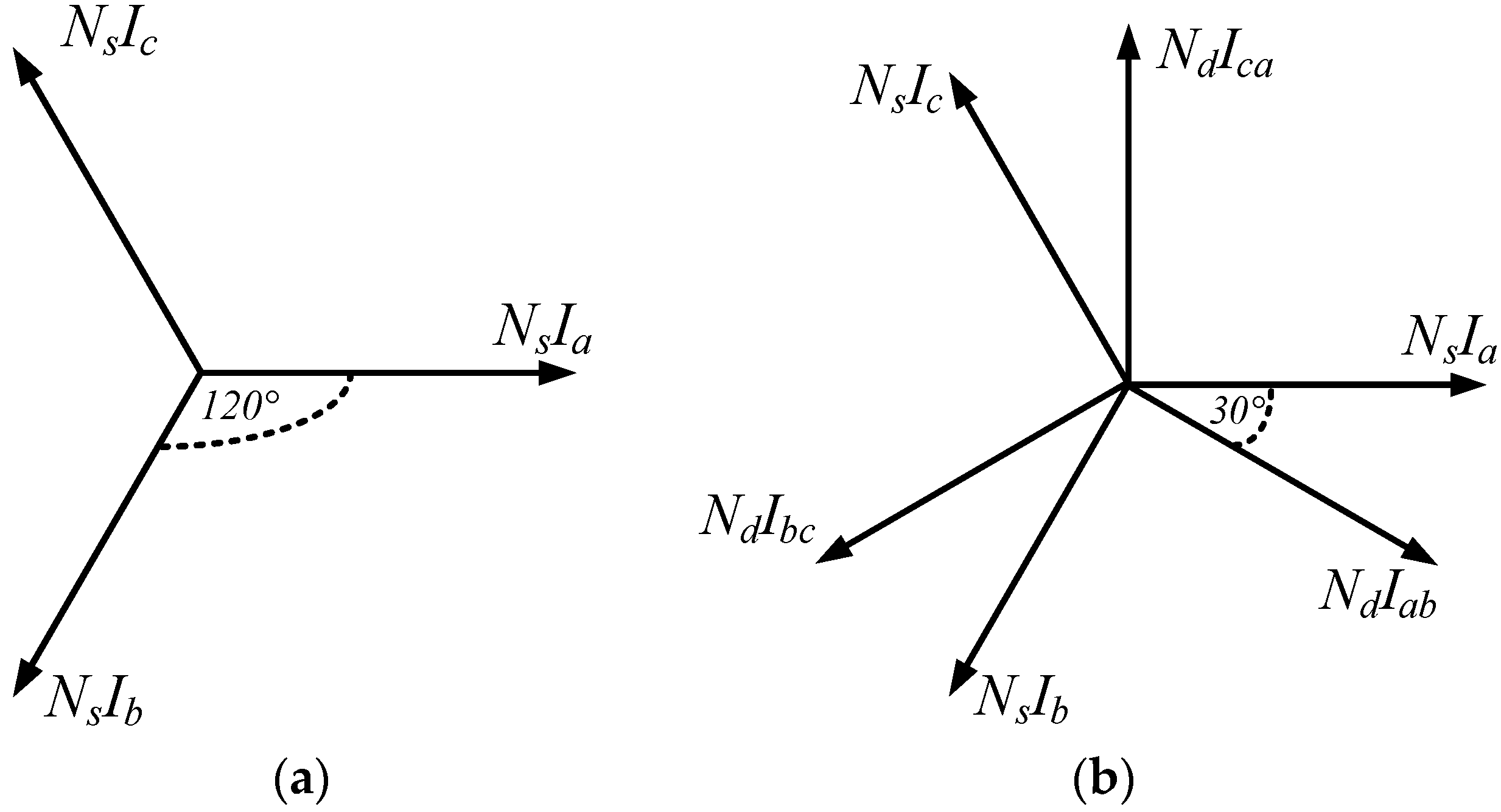
. Two parallel groups are employed for both the star and combined star–delta windings. A single-layer winding is employed in both different windings. The phasor diagram of MMFs of both the star and combined star–delta windings is sketched in
Figure 2.
Ns and
Nd are the number of turns of the star and delta coils, respectively.
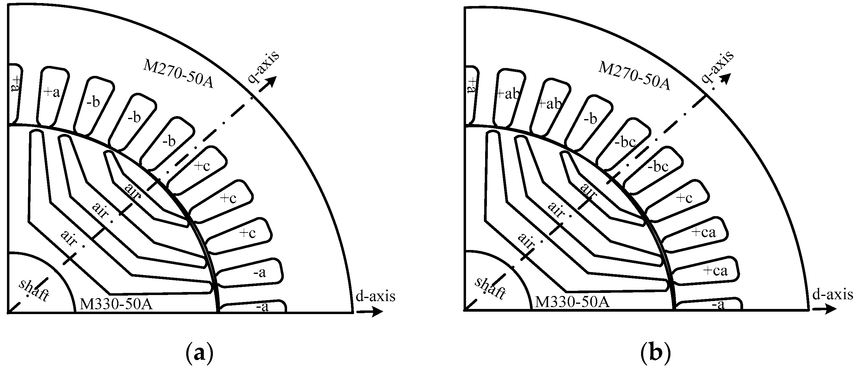
The rotor of the SynRM is a transversally laminated type with three flux-barriers per pole as shown in
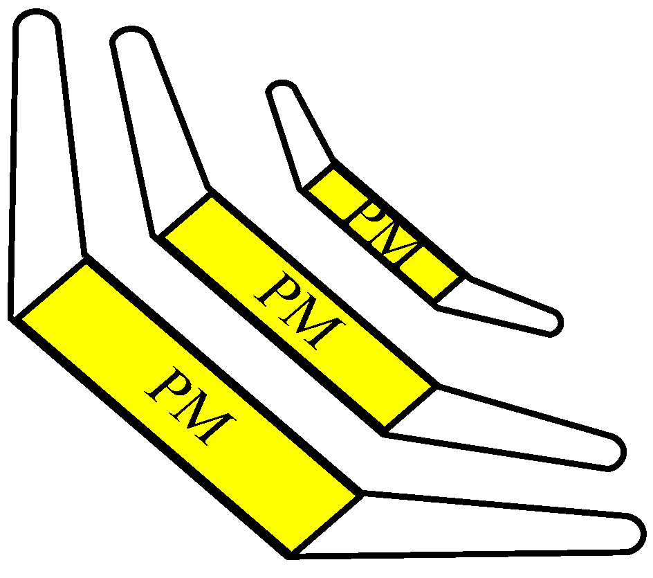
Figure 3. The PM-assisted rotor is simply the SynRM rotor with inserted ferrite PMs in the centre of the flux-barrier as sketched in
Figure 4. The ferrite PM type is Y30BH with a remanence (Br) and a coercive force (Hc) of 0.39 T and 234 kA/m, respectively.
The steel grade of the machine’s core plays a major role in the losses and hence the efficiency of SynRMs, as proved in [
7,
8]. It is shown in [
8] that the different steel materials result in different amounts of SynRM output power, and can increase the rated efficiency by 2.3% when using an NO20 grade instead of an M400-50A. However, the lower loss grades are more expensive both in raw material cost and in cutting cost [
7]. In a rough approximation, the lowest loss grade will have more or less double the cost compared to the highest loss grade. In order to compromise between the efficiency and the manufacturing cost of the prototypes, we have selected a lower loss grade for the stator core (M270-50A) than for the rotor core (M330-50A). This is because the stator core produces the majority of the iron losses of the SynRM.
From the aforementioned details, four prototype SynRMs can be obtained. The abbreviations given in
Table 2 are used in the remainder of the text.
3. Performance Comparison of SynRMs Using Finite Element Model (FEM)
Four SynRMs are modelled using 2D-MAXWELL ANSYS software (16.2.0, ANSYS, INC., Berkeley, CA, USA). The goal is to compare their performance, i.e., output torque, torque ripple, power factor, losses, and efficiency. In the simulation, the rotor is rotated at a fixed speed. In the stator, three-phase sinusoidal currents are enforced into the windings to simply emulate the current-controlled inverter that supplies the SynRM. For the Sd machines, the three sources are connected to the star coils as seen
Figure 1. Consequently, the currents in the delta coils are not enforced; they are computed by the coupled FEM and circuit model of
Figure 1. Notice that in the delta coils, triplen harmonics of the current may occur. These circulating currents are taken into account in the simulation.
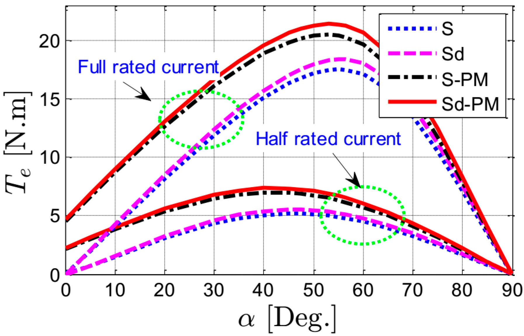
Figure 5 shows the output torque of the four SynRMs as a function of the current angle at rated speed (3000 rpm) and for half- and full-rated current (12.23 A). For half-rated current, it is obvious that the output torque of the Sd-PM, S-PM, and Sd machines increases by about 41.85%, 34.55%, and 6.41%, respectively, compared to the S machine at the optimal current angles. The optimal current angle represents the angle of the stator’s current vector with respect to the
d-axis that achieves the maximum output torque. It is evident from
Figure 5 that the optimal current angle is not a fixed value and depends on the stator’s current level and on the saturation behaviour of the machine’s core as well. This can be noticed in
Figure 5 by comparing the different curves of several machines and current levels. Furthermore, the output torque of the Sd-PM machine is higher than the S-PM by about 5.42% at the optimal current angles. This means that the amount of the increase in the output torque of the two machines with reluctance rotors (S and Sd) and the two machines with PM-assisted rotors (S-PM and Sd-PM) at the optimal current angles is not constant. This is because of the different
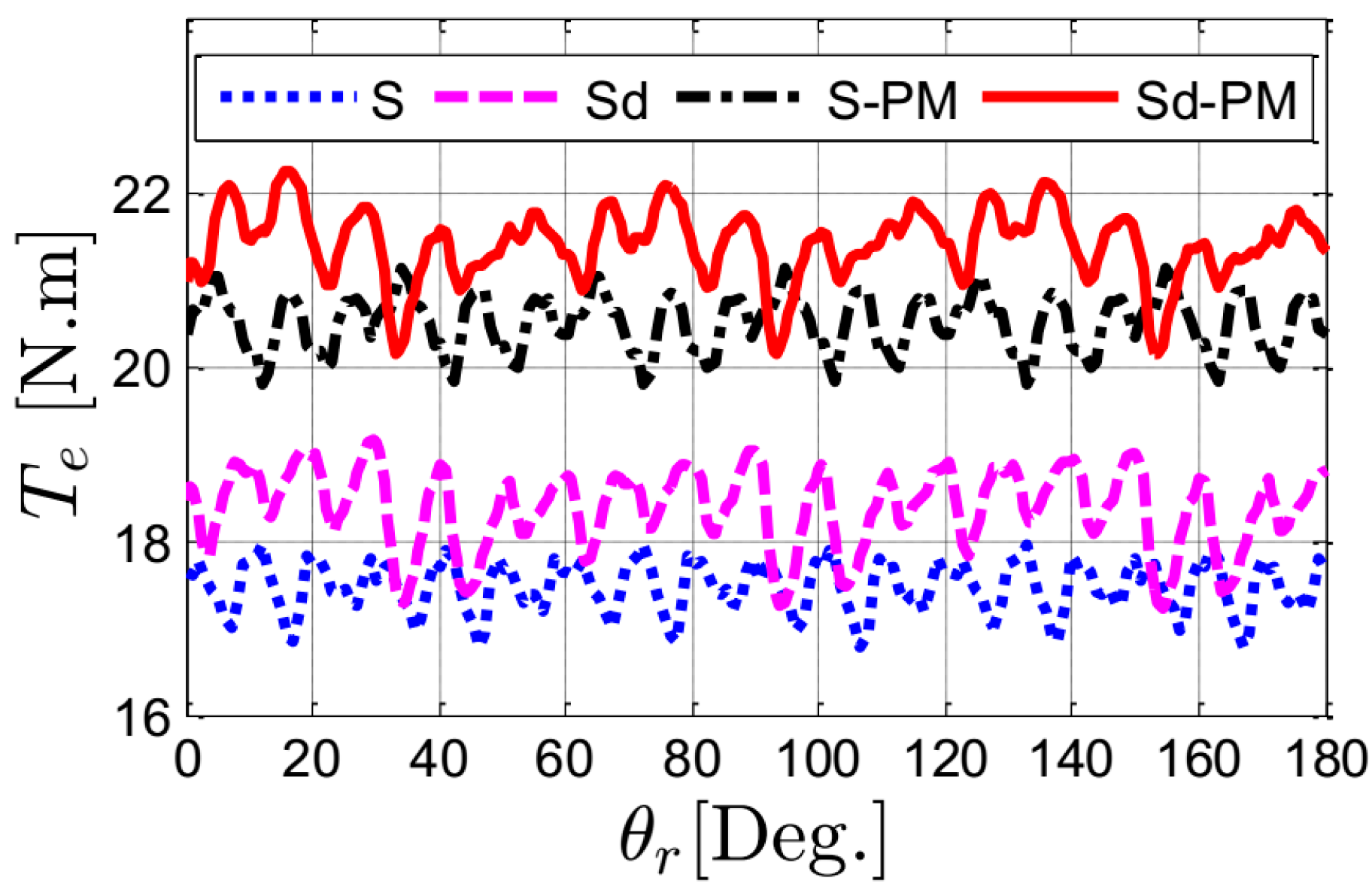
dq-axis currents and the saturation of the machine core. On the other hand, for full-rated current, it is clear from
Figure 5 that the output torque of the Sd, S-PM, and Sd-PM machines is higher than the S machine by about 5.02%, 17.01%, and 22.37%, respectively, at the optimal current angles. This can be seen in
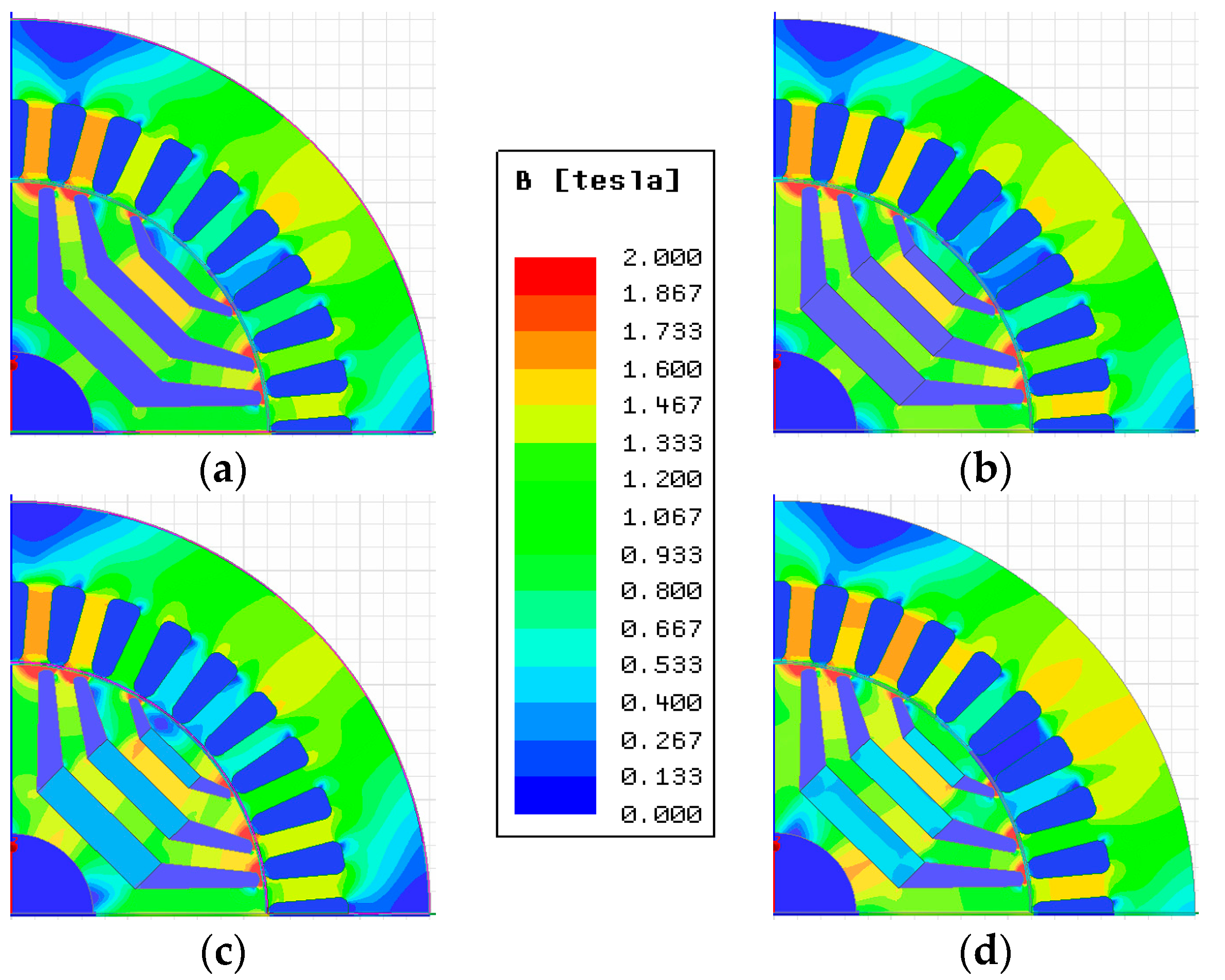
Figure 6, in which the output torque of the four machines is plotted for several rotor positions. An interesting observation here is that the increase in the output torque of the Sd, S-PM, and Sd-PM machines compared to the S machine is not a constant value; it is current-dependent. The flux density distribution of the four machines at
θr = 0° of
Figure 6 is shown in
Figure 7. It is clear that the Sd-PM machine has regions with much higher flux density compared to the other machines, in particular in the stator yoke.
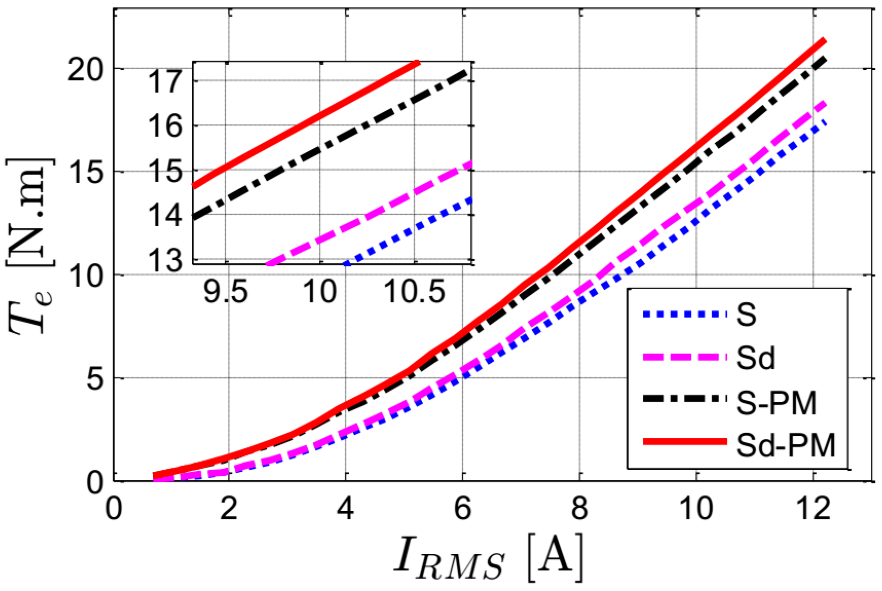
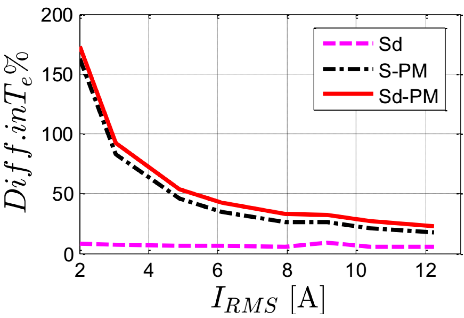
Figure 8 shows the output torque of the four machines as a function of the stator current at the optimal current angles and rated speed. The difference of the output torque (in percent) of the Sd-PM, S-PM, and Sd machines compared to the S machine is reported in
Figure 9. Clearly, both machines with PMs in the rotor (Sd-PM and S-PM) have much higher output torque compared to the S machine. The Sd-PM machine has an increase in output torque of about 22.37% for rated current and of about 150% for low current compared to the S machine. This is mainly thanks to the inserted ferrite PMs in the rotor and the improved winding factor of the star–delta connection. Furthermore, the difference in the output torque of the Sd-PM, S-PM, and Sd machines compared to the S machine decreases with an increase in the stator current. This is due to a decrease in the saliency factor difference with an increase in the current as shown in
Figure 10. The saliency factor is the ratio between the
d and
q axis inductances of the machine [
22]. For low current, the
dq-axis flux linkages of the machine are low. Consequently, the machine torque component produced from the saliency ratio is rather low compared to the torque component produced from the PMs. This shows a huge difference between the output torque of the machines with PMs (Sd-PM and S-PM) compared to the machines without PMs (S and Sd). With an increasing stator current, the
dq-axis flux linkages of the machine increase, hence the difference in the torque between the PM machines and PM-free machines decreases. The difference in torque between the machines becomes almost constant at a high stator current because of the saturation of the material core.
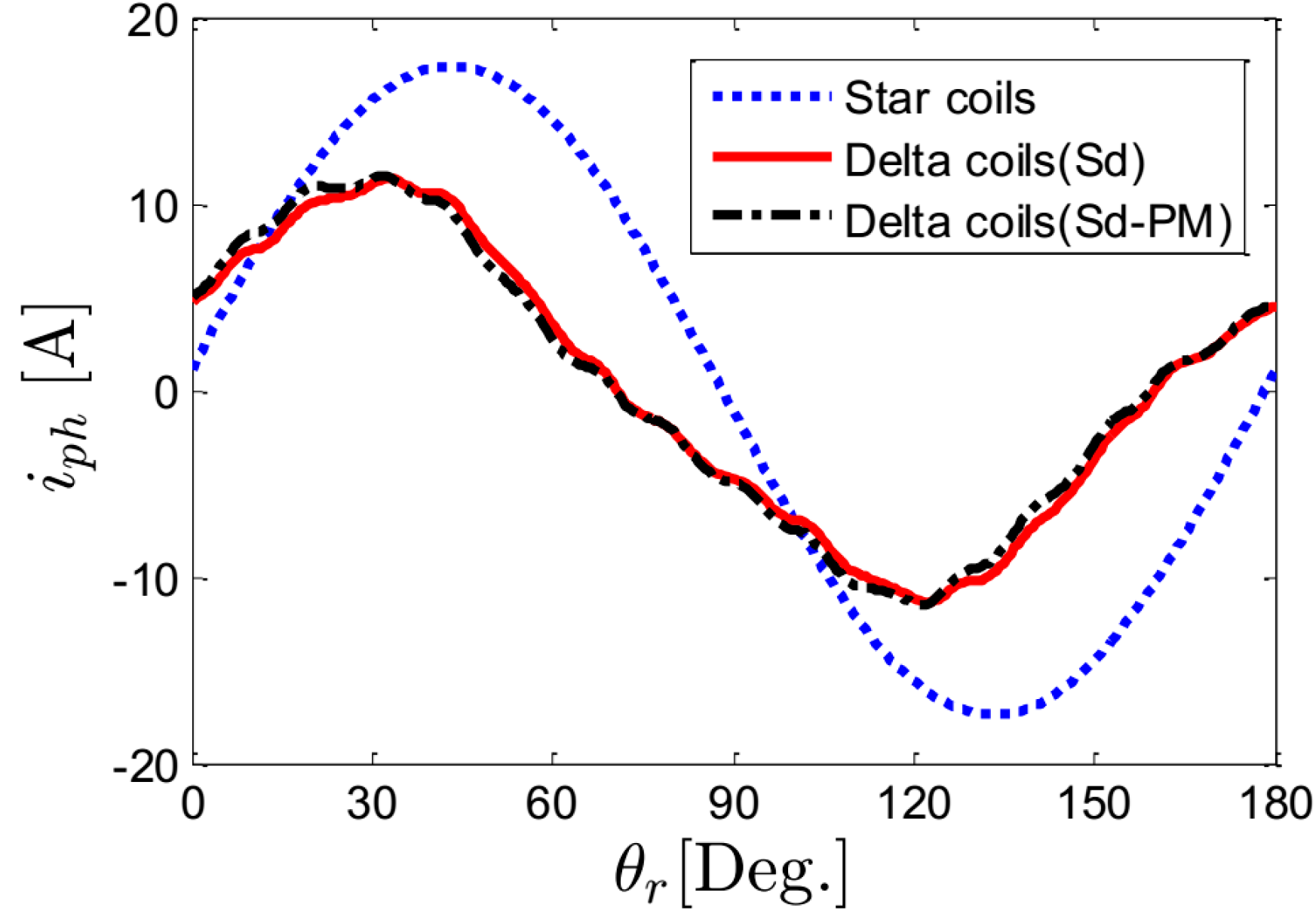
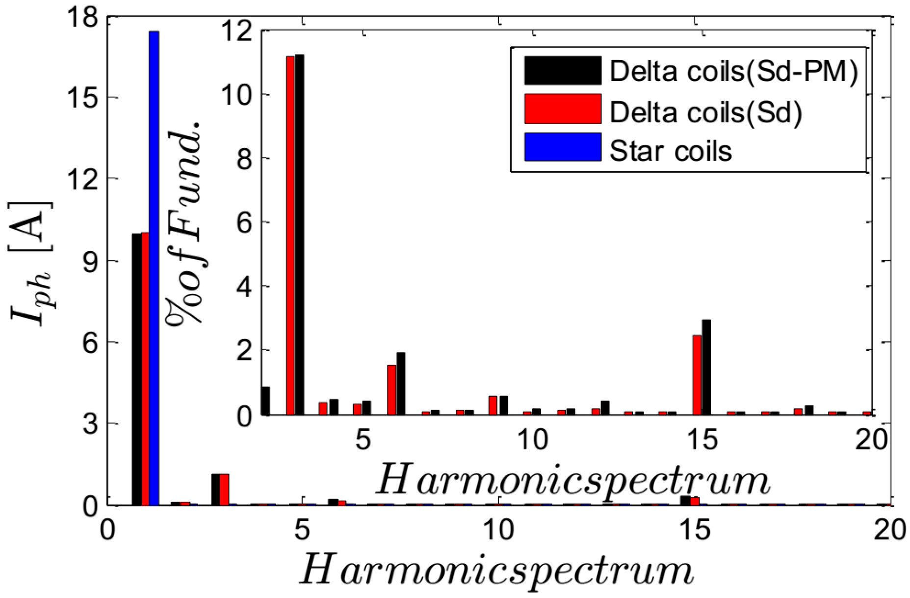
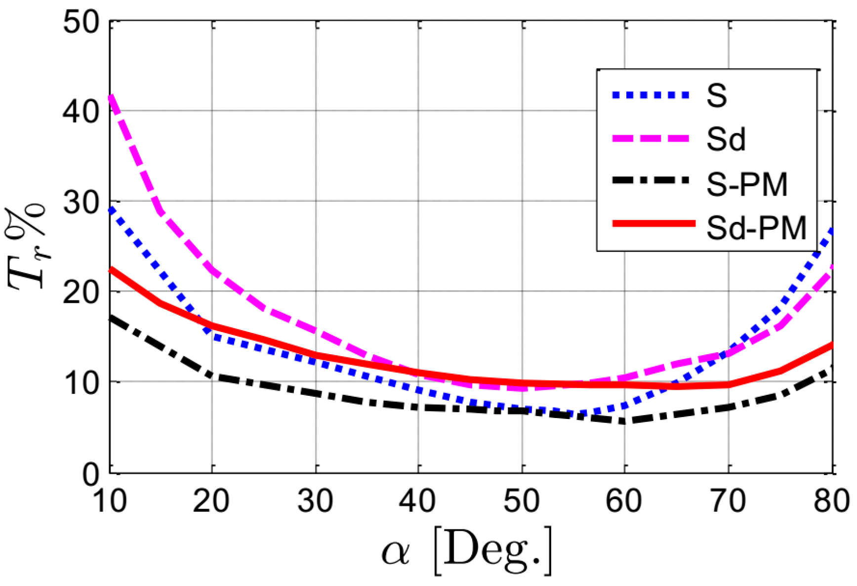
Figure 11 shows the variation of torque ripple (in percent) as a function of current angle at the rated conditions of the four machines. It is observed that the torque ripple of the four machines decreases with an increase in the current angle until an optimal angle, and then increases again. The value and the current angle of the minimum torque ripple is different for the four machines. This is due to the fact that the torque ripple is proportional to both the spatial harmonics of the magnetomotive force (MMF) and the machines’ average torque. Both the harmonics and the average torque of the four machines are different. By comparing the torque ripple of the four machines, it can be noticed that those machines with a star–delta connected stator have a higher torque ripple compared to those machines with star winding. This is due to two main reasons. On the one hand, the first reason is the circulating current components of the delta coils. Although these components do not contribute to average torque production, they negatively affect the torque ripple’s magnitude. The currents in the star and delta coils of the different connections at the rated conditions and optimal current angle are reported in
Figure 12. The star currents are enforced as pure sinusoidal currents—as mentioned before—in all the different connections, while the delta currents in the combined star–delta windings (Sd and Sd-PM) are computed based on FEM. It is evident that the delta coils have circulating current components. The harmonic spectrum of the currents is reported in
Figure 13. Apart from the fundamental component, the dominant harmonic component is the 3rd in both Sd and Sd-PM, and its value is approximately the same: about 11.2% of the fundamental component of the Sd machine’s connection. These harmonics negatively affect the torque ripple, as observed in
Figure 11. Notice that the difference of the torque ripple % between the Sd-PM and Sd machines is due to the difference in the harmonic components as seen in
Figure 13. On the other hand, the second reason is due to the fact that the rotor flux-barrier angles have been optimally selected based on the machines with a star connection. The influence of these angles is mainly on the torque ripple of the SynRMs as shown in [
6]. This means that it is possible to optimize the SynRM rotor flux-barrier angles with respect to the combined star–delta connection, and hence the torque ripple can be decreased. The torque ripple in
Figure 11 increases from about 6.44% (star connection) to about 9.5% (star–delta connection).
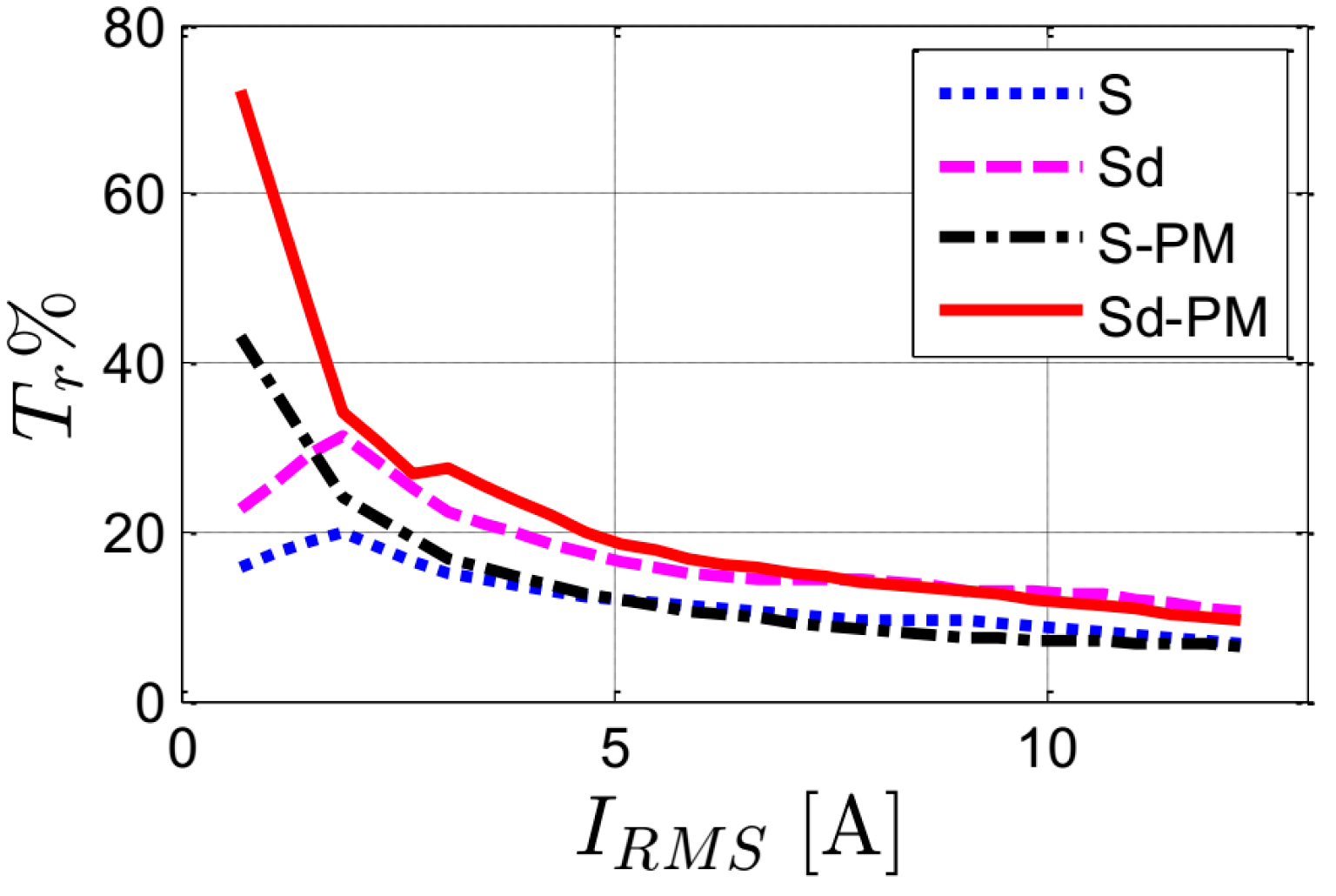
For the four machines,
Figure 14 shows the variation of the torque ripple (in percent) for different stator currents at rated conditions and optimal current angles. It is seen that the SynRMs’ torque ripple decreases with increasing stator current. This is mainly because of the increase in the average torque with the stator current and the fact that the ripple is given as a percentage of the average torque. In an absolute peak-to-peak value, the ripple increases linearly with an increase in the stator current, as presented in [
22]. However, the peak-to-peak value has a smaller effect on the torque ripple than the average torque. In addition, the Sd machines have a higher torque ripple than the S machines with the star connection as explained before.
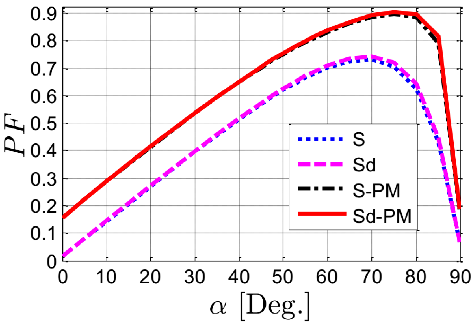
The power factor of the four SynRMs as a function of the current angles for rated conditions is shown in
Figure 15. It is observed that the SynRMs’ power factor increases with an increase in the current angle until an optimal value. This is because of the increase in the saliency ratio. Note that the maximum value is at a higher current angle than for the maximum torque in
Figure 5.
Figure 15 confirms findings in other studies in the literature, e.g., [
16], that adding PMs in the rotor increases the power factor dramatically. However, the figure shows that there is almost no influence on a machine’s power factor when using a combined star–delta connection instead of the conventional star connection, both for the machines with and without ferrite PMs. This is because the combined star–delta winding has a non-significant influence on the phase shift between the stator current and voltage vectors.
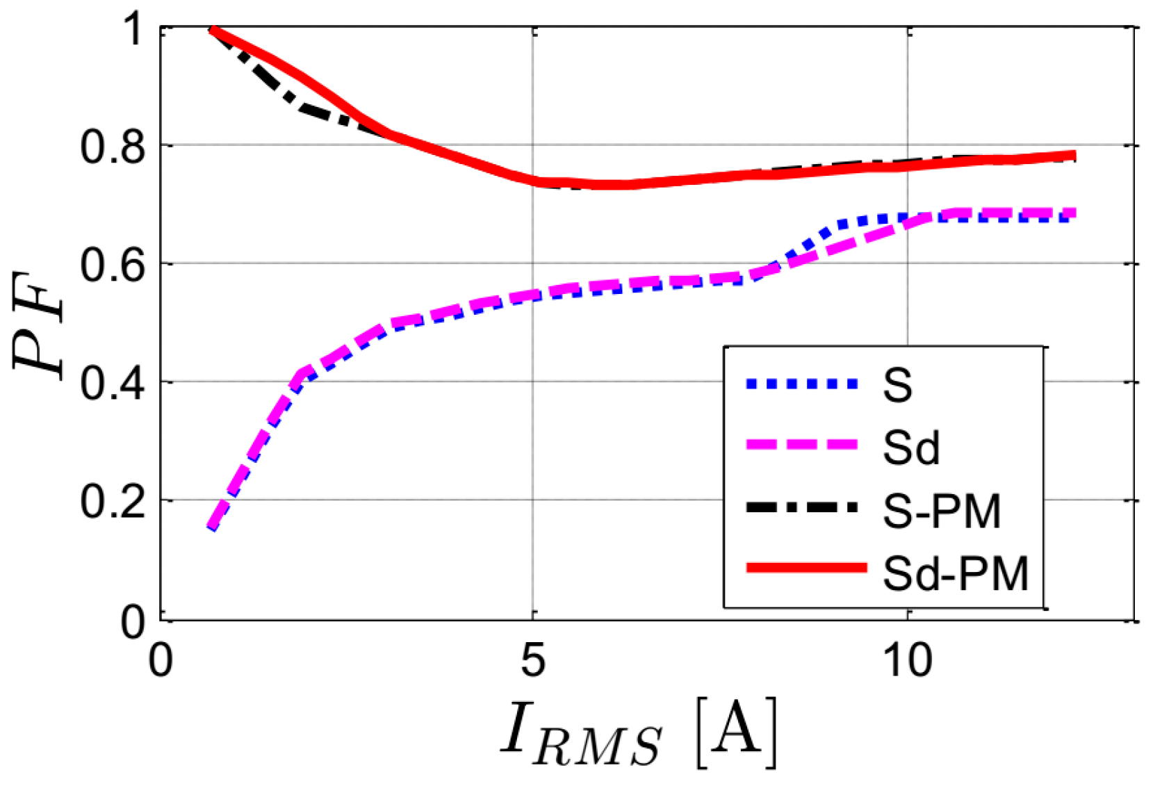
The variation of the power factor of the four SynRMs as a function of the stator current is reported in
Figure 16. The simulations are done at the optimal current angles and rated speed. Notice that the step variation in the power factor in
Figure 16 is due to the variation of the optimal current angle based on the stator’s current magnitude. We already know from
Figure 15 that the ferrite PMs increase the power factor significantly. In addition, we learn from
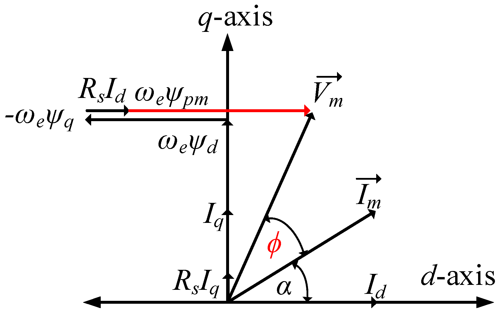
Figure 16 that the gain in power factor becomes lower at high stator currents. This is because of the increase in the flux linkage of the machine, resulting in an increase in the phase angle between the voltage and current vectors. This can be understood simply from the machine vector diagram shown in
Figure 17. The voltage and torque equations of PMaSynRM are be given by:
where
ψ represents the flux-linkage,
I is the stator current,
V is the stator voltage,
Rs is the stator resistance and
ωe is the electrical speed of the PMaSynRM. The subscript symbols
d,
q, and
pm are direct, quadrature and permanent magnet, respectively.
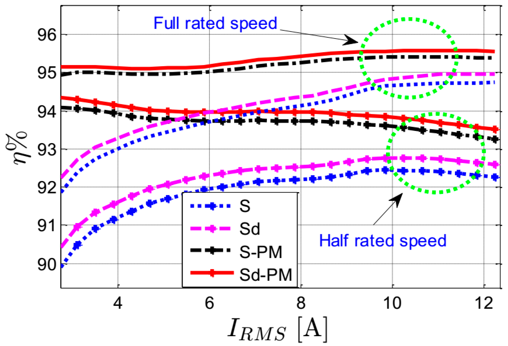
The simulated efficiency of the four SynRMs as a function of the stator current at the optimal current angles and for half- and full-rated speed is reported in
Figure 18. The efficiency calculation includes only the copper and iron losses of the machine. The copper losses are obtained using the measured winding resistance of the machine and the current magnitude, which are equal for star and combined star-delta connections. This is because the increase in the number of turns of the delta coils is compensated for by a reduction of same factor (
) in the cross-section area. The iron losses are computed using the magnetic flux density
B resulting from the FEM calculations for several points and positions. Then, the iron losses are obtained as in [
8].
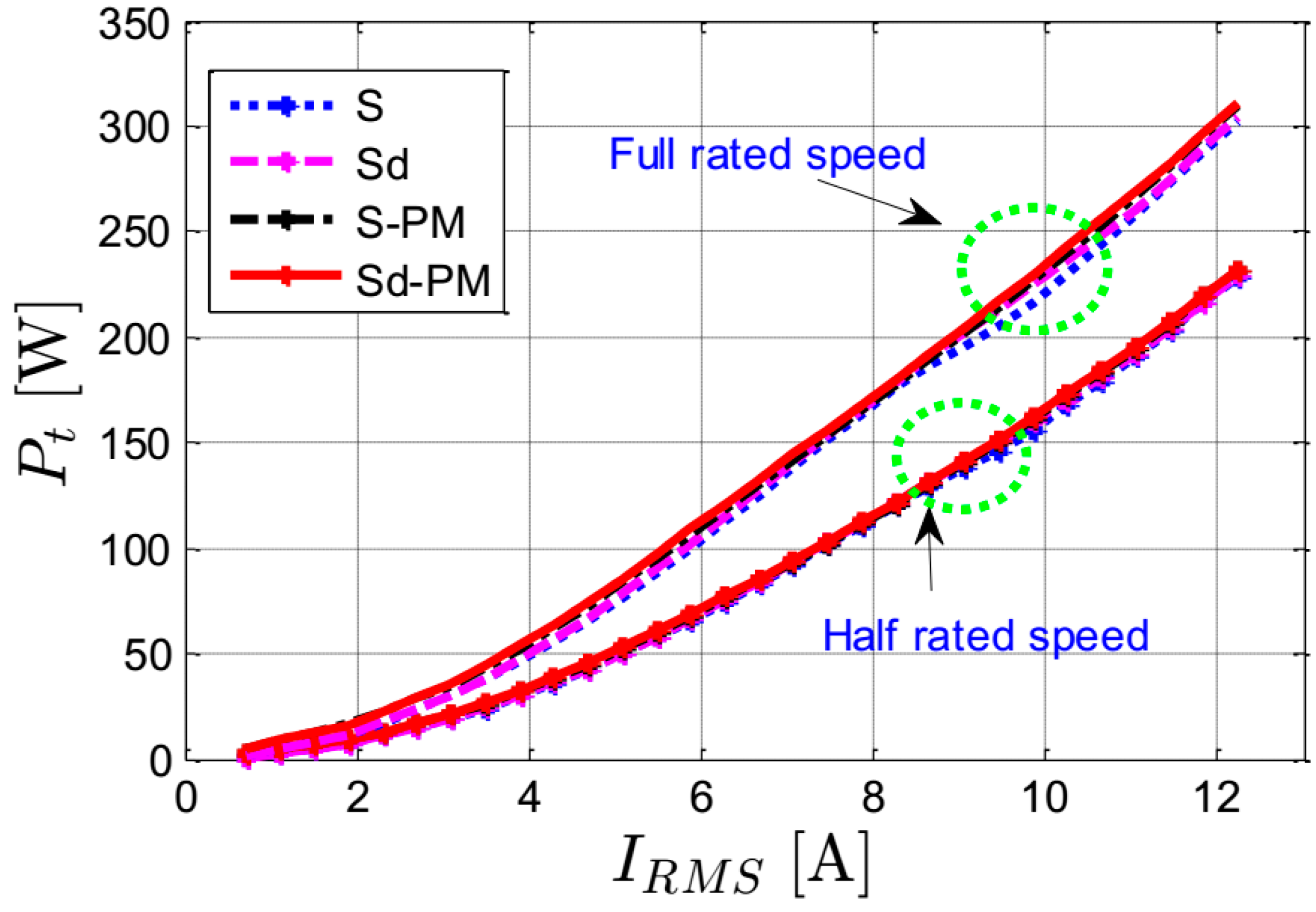
Figure 18 shows a slight increase in the machines’ efficiency using the combined star-delta winding instead of the star one: about 0.33% points higher at maximum. Moreover, the efficiency of the machine is increased slightly when inserting PMs into the rotor. This is clear when comparing the efficiency of the Sd-PM machine with that of the S machine: about 1.25% points higher for half-rated speed and 0.82% points for full-rated speed. The low difference in the efficiency between the machines can be understood from
Figure 19, which shows the computed total losses of the four machines for half- and full-rated speeds. The strong increase with current indicates that the copper losses (which are the same for the machines) are dominant. It is clear that the losses are approximately similar; only a slight increase in the losses of the SynRMs having combined star–delta windings occurs due to circulating harmonic currents.
4. Experimental Validation
For the validity of the simulated results presented above, two different stators and rotors are manufactured. The two stators have similar geometrical parameters: one has conventional star winding and the second contains the star–delta winding. The two rotors are flux-barrier type and have four poles with three flux-barriers per pole. The rotors have similar geometrical parameters: one rotor with ferrite PMs inserted in the center of the flux-barriers (
Figure 4), and a second one without PMs. Four prototype SynRMs can be obtained using the two stators and the two rotors with the parameters given in
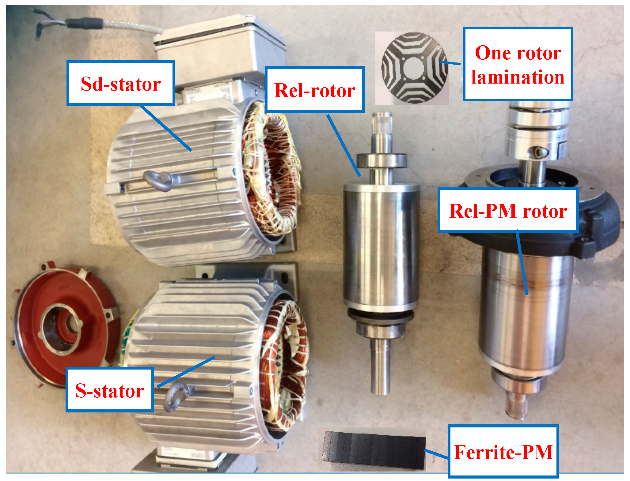
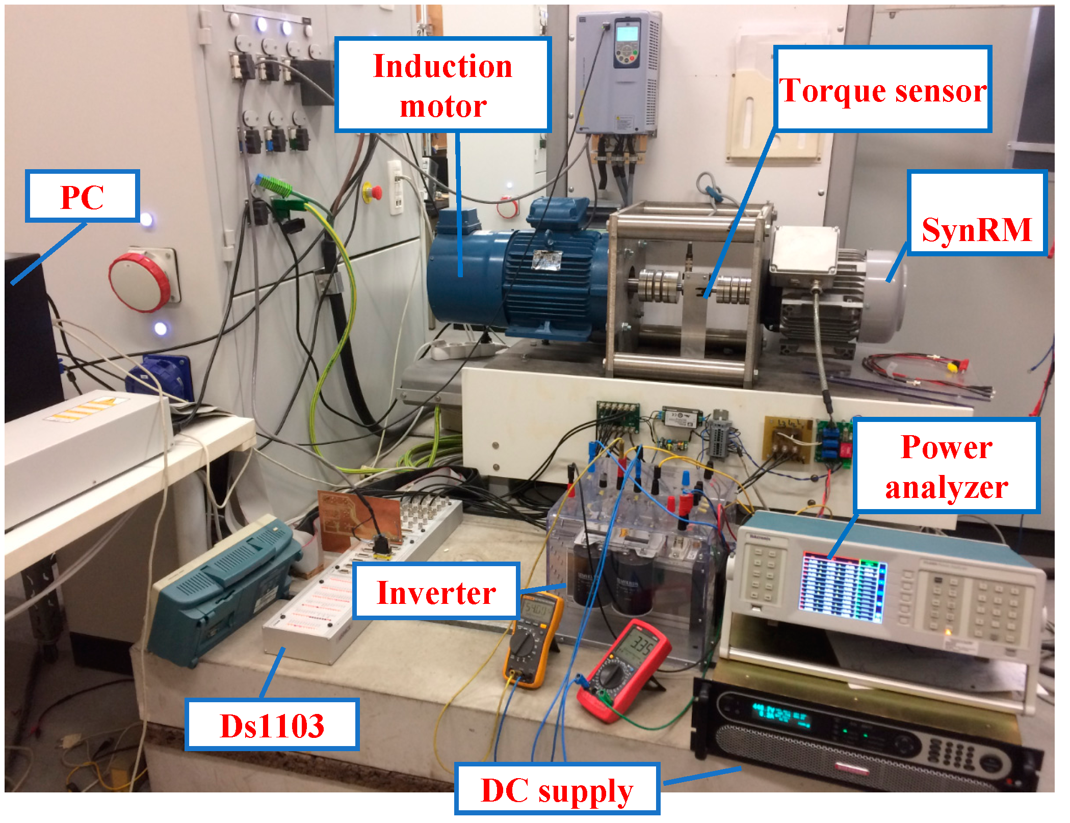
Table 1. Photographs of the prototypes and the complete experimental setup are reported in
Figure 20 and
Figure 21, respectively.
In the experimental setup, a 9.3 kW induction motor is controlled by a three-phase industrial inverter and employed to drive the SynRM at the desired speed. The SynRM is driven in torque control mode by controlling a conventional three-phase voltage source inverter using a pulse width-modulated technique. The direct current (DC) bus voltage and the switching frequency of the inverter are fixed at 600 V and 6.6 kHz, respectively, for all of the measurements. The dSpace 1103 platform is employed to control the inverter of the SynRM. To measure the output torque of the SynRM, a torque sensor is mounted between the induction motor and the SynRM. The electric input power is measured using a power analyser. An incremental encoder is used to measure the motor speed.
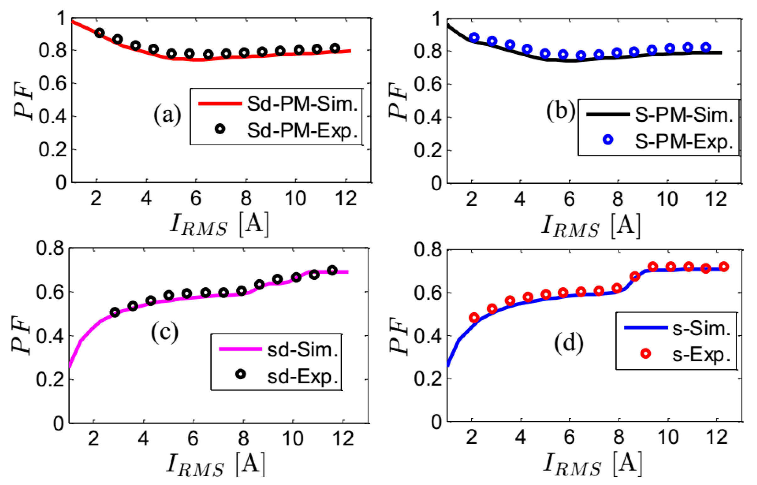
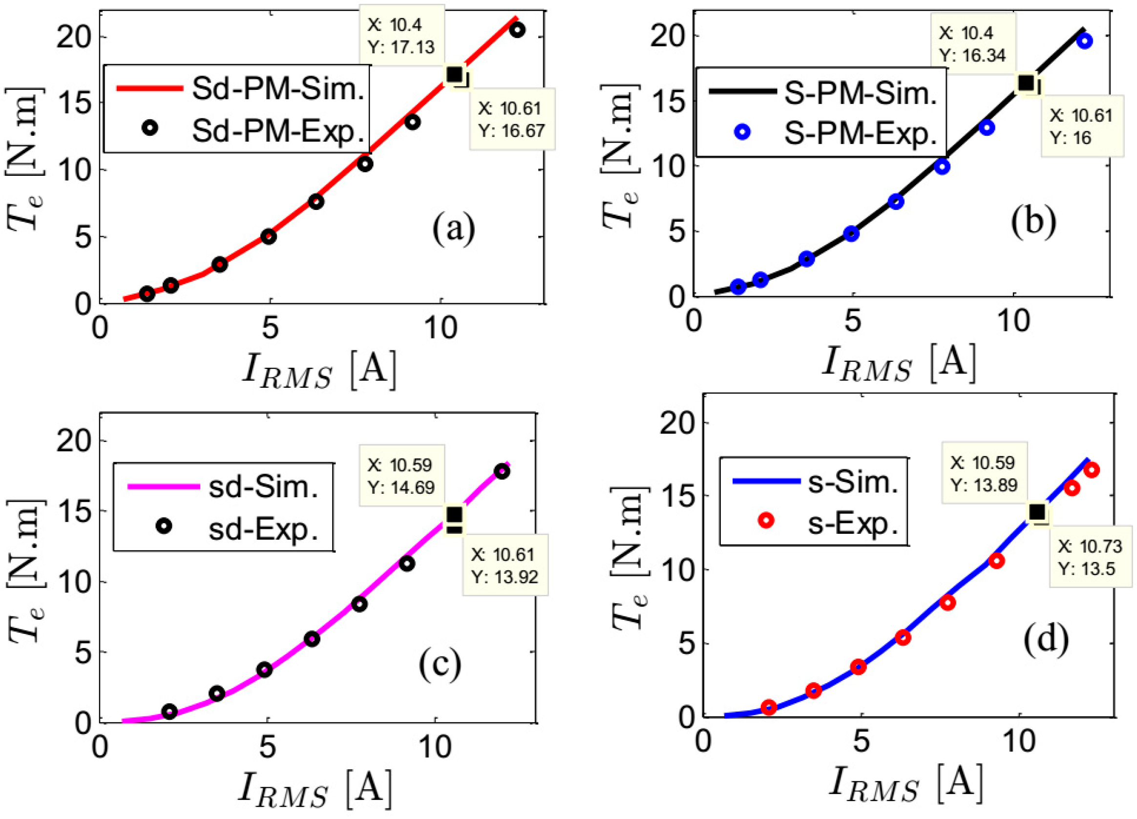
Figure 22 shows the measured and simulated output torque of the four prototypes as a function of the current angle at half-rated current and speed. The simulated and measured results correspond very well. The measured and simulated power factor and output torque of the four SynRMs as a function of the stator current at the optimal current angles and rated speed are reported in
Figure 23 and
Figure 24, respectively. Good matching between the simulated and measured results is noticed. It is noticed that the discrepancy between the simulated and measured results is about 5% at maximum.
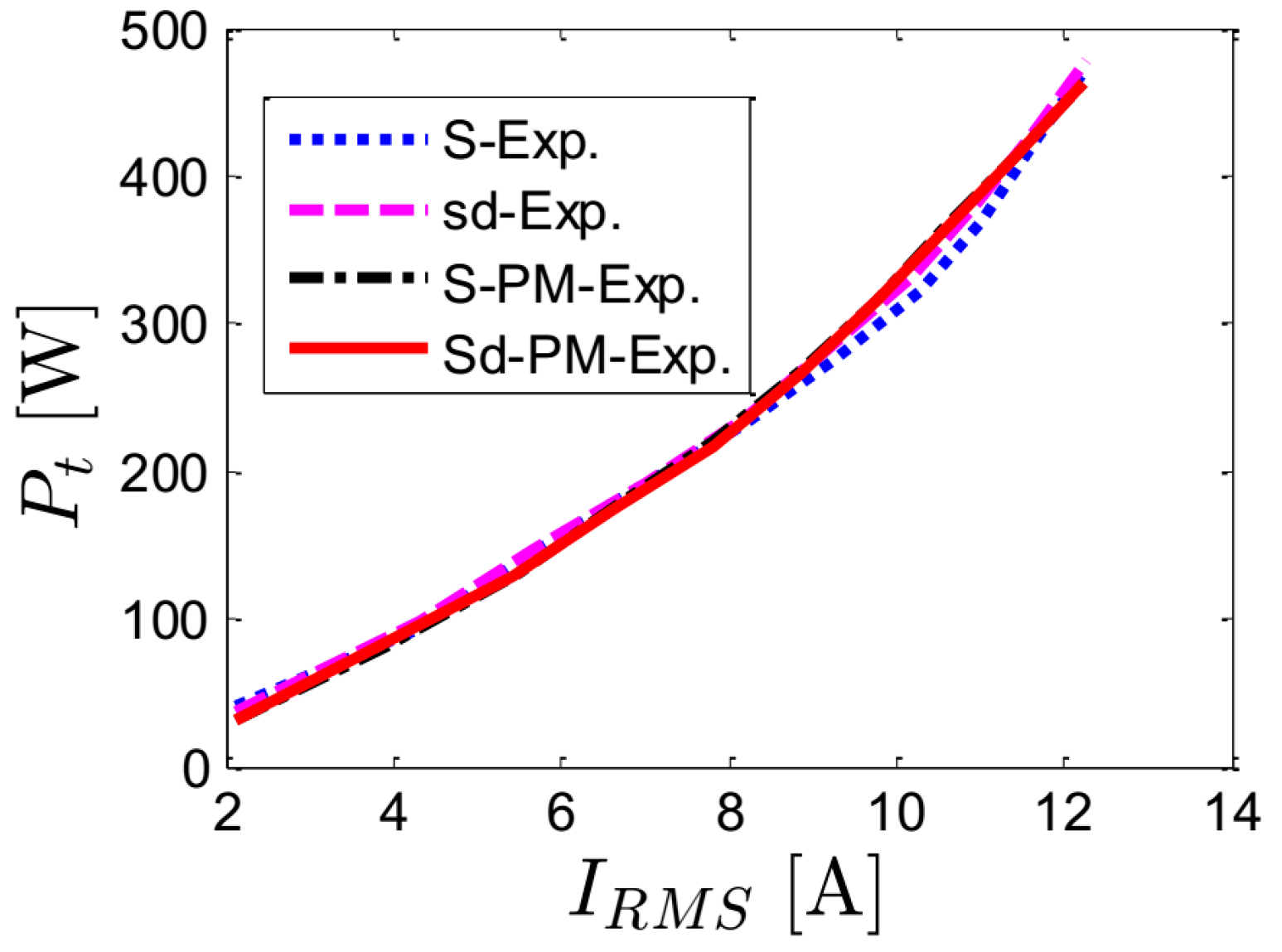
The measured total losses of the four prototypes as a function of the stator current at full-rated speed is shown in
Figure 25. The measured losses are the difference between the measured output and input powers of the machines. The difference in losses of the four prototypes is not significant, similar to the trends of the simulated results. However, the simulated losses are lower than the measured losses. This is because, in the simulation, the mechanical and pulse width modulation (PWM) losses are not considered. In addition, the computed iron losses may be underestimated because the degradation of the material properties by cutting and press fitting is not included.
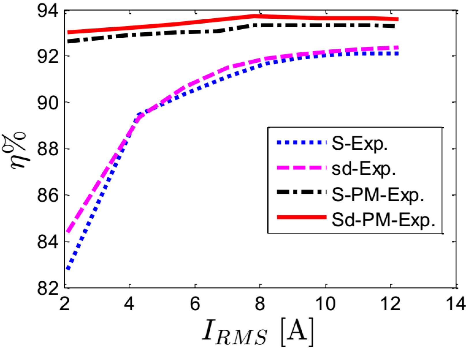
Figure 26 reports the measured efficiency of the four prototypes for several loading currents at the optimal current angles and at the rated speed (3000 rpm). It is clear that the efficiency of the SynRMs improves slightly using the star–delta winding and improves significantly by adding PMs in the rotor. The Sd-PM machine has the highest efficiency: about 93.60% at the rated current. This is higher than the required minimum for the IE4 super premium efficiency class [
23]: about 92.50% for a four-pole 5.5 kW induction motor. The rated efficiency for the other machines is: 92.10% for the S machine, 92.36% for the Sd machine, and 93.29% for the S-PM machine.
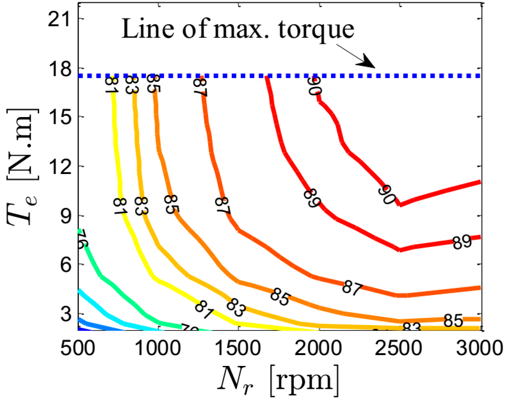
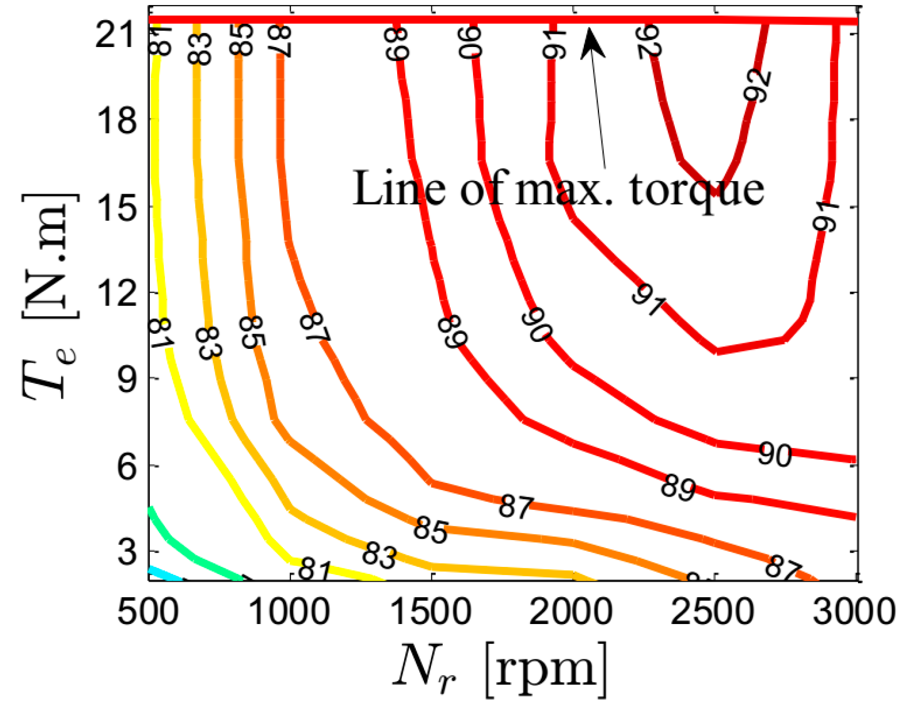
Figure 27,
Figure 28,
Figure 29 and
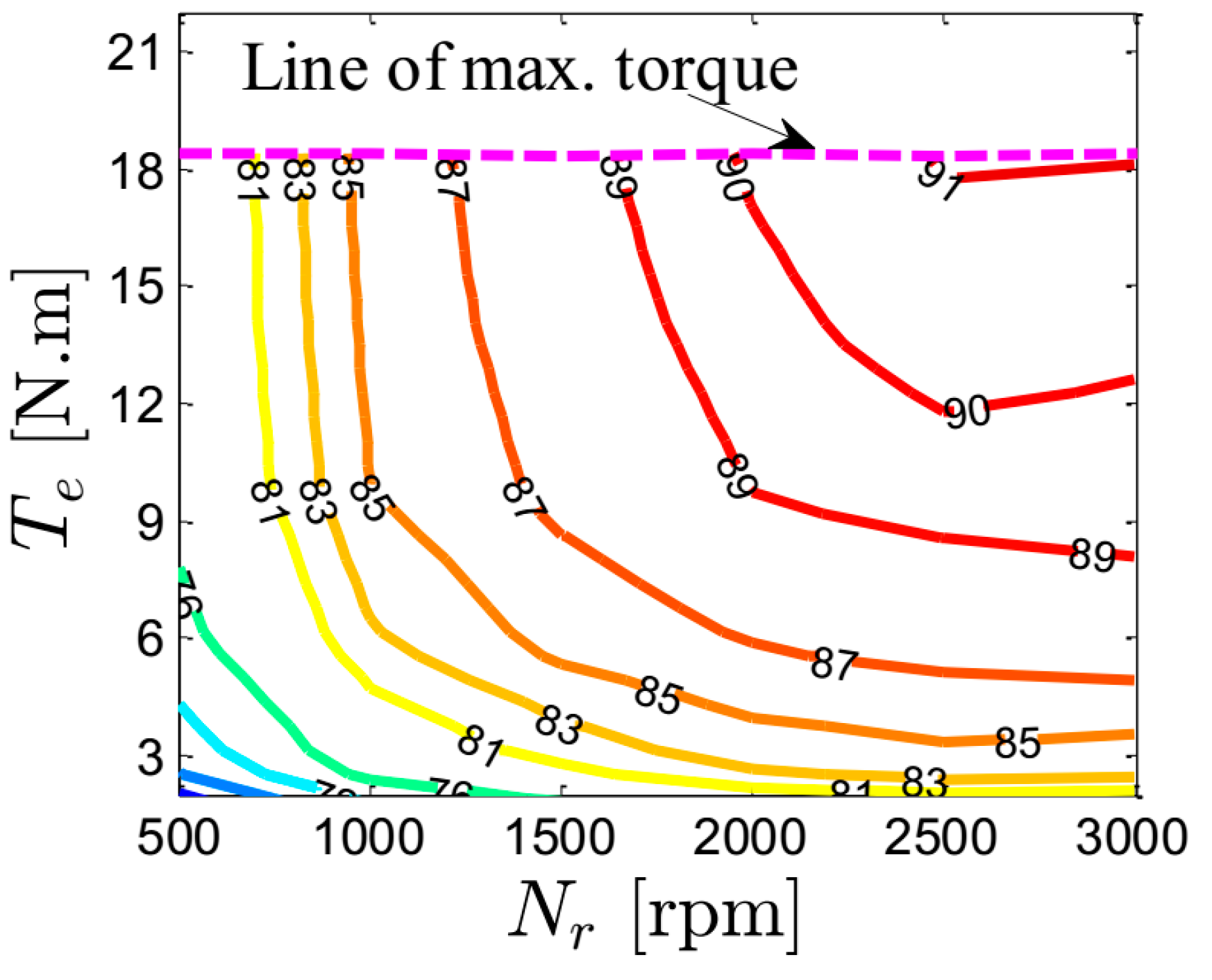
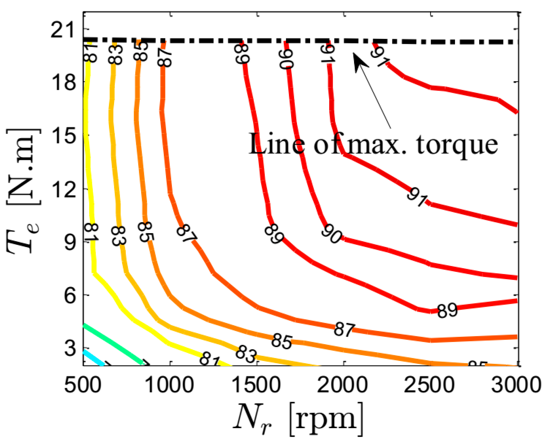
Figure 30 report the measured efficiency maps of the whole drive system (prototype + inverter) at optimal current angles for speeds and currents up to the rated values (3000 rpm, 12.23 A). A shown before, the maximum output torque of the four machines is different and the Sd-PM machine gives the highest output torque. In general, and in correspondence with the literature [
15], adding ferrite PMs in the rotor of a SynRM increases the machine’s efficiency. It is worth noting that the efficiency of the Sd-PM machine (
Figure 30) is much better than for the other machines over the whole operating range, but especially at low loads. This is because the output torque of Sd-PM is much higher than the other machines for the same currents. This happens especially for low currents as depicted in
Figure 10. By comparing the machines regarding the winding configuration, the machines with combined star–delta windings have better efficiency compared to the machines with the conventional star connection, especially under partial loads. This is because of the increased torque-to-current ratio.
5. Conclusions
This paper investigates and compares the performance (output torque, power factor, torque ripple, and efficiency) of four prototype SynRMs with identical geometry of the stator and rotor stacks; the two stators have different winding layouts and the two rotors differ in having ferrite PMs. The winding layouts are the conventional star connection and the combined star–delta winding, while the rotors are a flux-barrier rotor type with and without ferrite PMs.
For the same copper volume and current, the machine with star–delta winding and ferrite PMs inserted into the rotor (Sd-PM) corresponds to an approximately 22% increase in torque at rated current and speed compared to the machine with a conventional star connection and a reluctance rotor. This enhancement is mainly thanks to adding the ferrite PMs in the rotor and the improvement in the winding factor of the combined star–delta winding. Moreover, the torque gain is current-dependent: it increases up to 150% for low current compared to the conventional star connection with a reluctance rotor. An interesting observation here is that the efficiency of the machine with a combined star–delta connection and a PM-assisted rotor (Sd-PM) is high for partial loads. In addition, it can reach 93.60% for rated conditions, which is higher than the required minimum for the IE4 super premium efficiency class. This is because of the increased torque-to-current ratio. Consequently, this machine (Sd-PM) is a very promising candidate for several industrial applications, e.g., PV pumping systems and automotive applications.
On the other hand, there is a non-significant influence on the power factor and losses of SynRMs using different winding connections. The theoretical findings are experimentally validated using four identical prototype machines with different rotors and winding layouts.


