3.1. Algorithm Principle
Compared with hydropower stations, TPS are characterized by a weaker peak shaving ability, higher operation costs, and relatively lower reliability, so they should avoid shaving peak load as much as possible. In the traditional calculation of the balance of electric power and energy, TPS are grouped together and seen as one station whose output is to make up the power system’s remaining load after the load of every hydropower station has been assigned. However, by using this calculation method, the daily output process of each thermal power station cannot be obtained, and in some cases where there are no constraints on monthly or daily generated energy, the monthly energy balance cannot be reached.
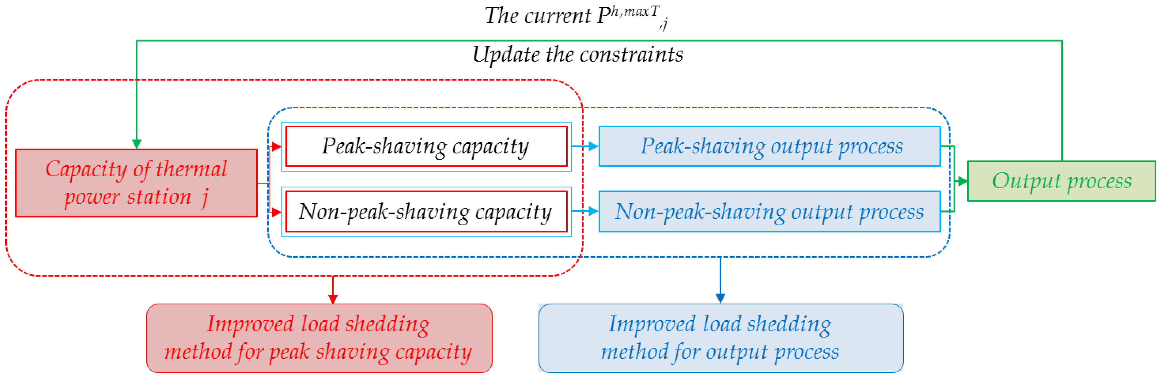
Based on the ILSM [
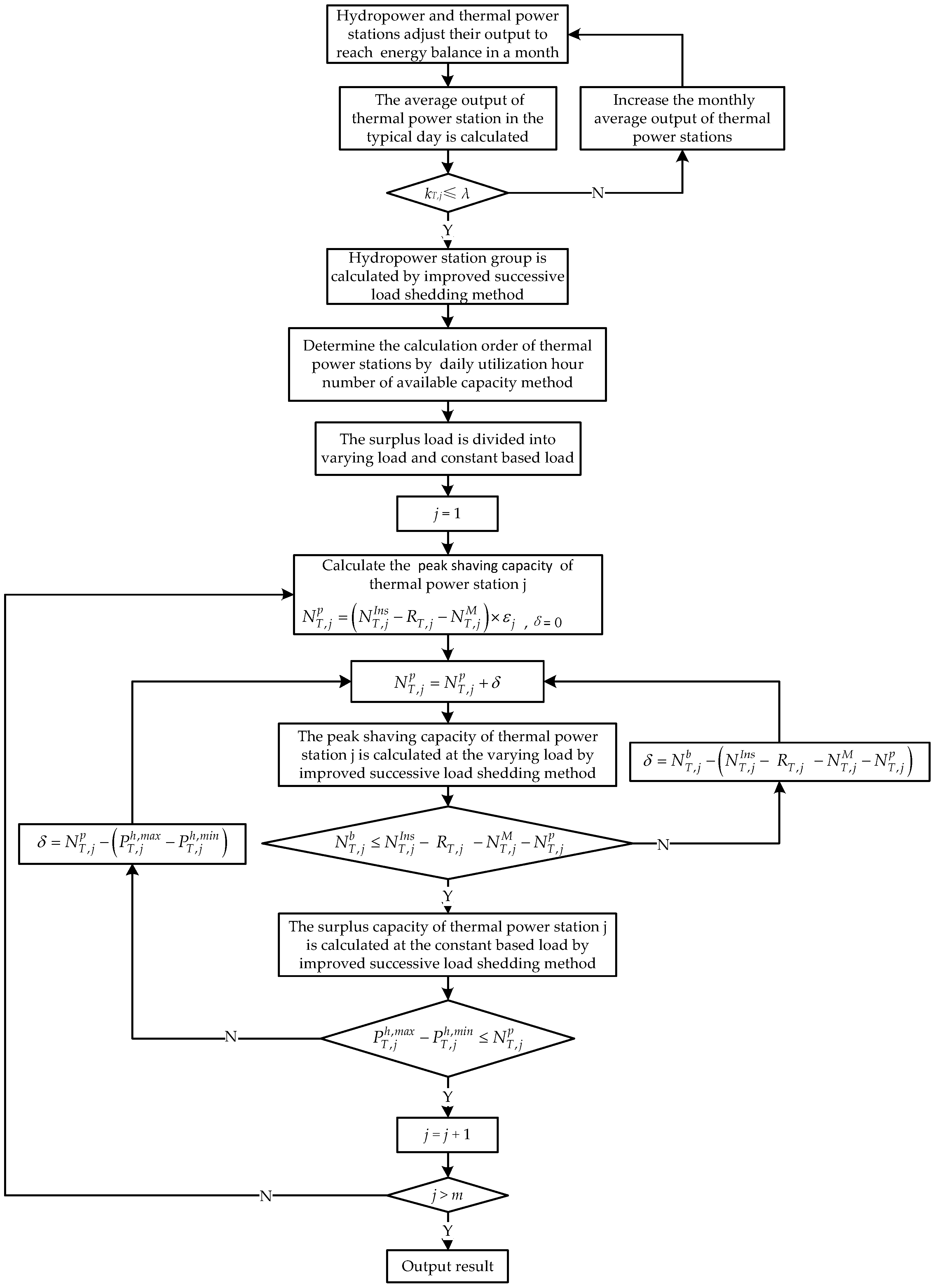
3] and the idea of a nested structure, the typical daily output process of a single thermal power station can be divided into two parts: the peak shaving output process, and the non-peak shaving output process. It can be regarded as the output process that is worked out with peak-shaving capacity and non-peak-shaving capacity of the thermal power station by using the ILSM. This can be viewed as a two-layer nested structure. In the outer layer where the constraint of generated energy is left out, the working capacity of a thermal power station is divided into the peak shaving part and the non-peak shaving part, according to the constraint of peak shaving capacity and the iterative idea of the ILSM. In the inner layer, with the obtained peak shaving and non-peak shaving capacity, the ILSM is used to work out the peak shaving output process and the non-peak shaving output process, respectively. Finally, by adding the two processes together, the typical daily output process of the thermal power station is produced. In the case of multiple TPS for calculation, the method of the available capacity’s daily utilized hours is used to determine the calculation order of the TPS. The calculation principle is illustrated in
Figure 1.
3.2. Basic Constraints
In the balance calculation of the electric power and energy of a thermal power station, there are some constraints that need to be satisfied.
The upper and lower limits of output:
where
and
are the lower limit and the upper limit of output of thermal power station
j in MW, respectively;
is the output of thermal power station
j in the
hth period in MW; and
h is the index for a certain time period, ranging from 1 to 24.
The constraint of peak shaving capacity:
where
and
are the minimum and maximum typical daily output of thermal power station
j in MW, respectively;
is the peak shaving capacity of thermal power station
j in MW; and
εj is the peak shaving capacity factor of thermal power station
j.
The ramping constraint:
where
is the ramping ability of thermal power station
j in the contiguous period in MW.
The constraint of generated energy:
where
is the typical daily average output of thermal power station
j in MW.
The constraint of electric power:
And all of the parameters are non-negative.
3.5. Calculation Steps of the Nested-Structured Load Shedding Method
This paper does away with the approach that groups TPS together to jointly undertake the power system’s remaining load, which is the case when using the traditional load shedding method. As an alternative, the calculation of TPS is conducted one by one, in the same way that hydropower stations are treated. However, because of the constraint of peak shaving capacity, TPS are different from hydropower stations, whose whole working capacity can be used for shaving peak load. So the remaining load of the power system is divided into two parts: the constant base load and the varying load (such as peak load or waist load). Firstly, the peak shaving capacity of a thermal power station is taken into the constraint of electric power, its typical energy generated daily is taken into the constraint of generated energy, and the ILSM is employed to shed the power system’s varying load. Then, the power constraint is changed to involve the remaining working capacity of the thermal power station, while the energy constraint is changed to involve its remaining typical daily generated energy left by the preceding calculation. Next, the load shedding method is applied to shed the system’s base load. By adding the two resulted output processes together, the typical daily output process of the thermal power station can be obtained. The detailed calculation procedure is described as follows.
Step 1: Calculate the generated power corresponding to the power system’s remaining load, according to the following formula:
where
E is the generated power corresponding to the power system’s remaining load in MW∙h; and
t is the duration of the
hth period.
Divide the power system’s remaining load into the varying load and the constant base load:
where
and
are the varying load and the constant base load of the power system’s remaining load in the
hth period in MW, respectively; and
is the minimum load of the power system in MW.
Step 2: Calculate the peak shaving capacity of thermal power station j according to Formula (23). Initially, the maximum working capacity of the thermal power station is assumed to be its maximum output.
Step 3: With the peak shaving capacity and the typical daily generated energy of thermal power station
j being constrained, use the ILSM [
3] to shed the power system’s varying load to get the peak shaving output process and typical daily generated energy of thermal power station
j.
where
is the peak shaving generated energy of thermal power station
j on a typical day in MW∙h; and
is the peak shaving output of thermal power station
j in the
hth period in MW.
Step 4: Calculate the remaining generated energy and working capacity required of thermal power station
j:
where
is the remaining generated energy required of thermal power station
j on the typical day in MW∙h; and
is the remaining working capacity required of thermal power station
j in MW.
Step 5: If:
where
is the peak shaving capacity required of thermal power station
j in MW, the remaining working capacity of thermal power station
j cannot meet its electricity demand. So, it is necessary to reduce its peak shaving capacity in order to generate less peak shaving energy until the condition expressed by Formula (37) is met. Use the load shedding method to iteratively calculate the peak shaving capacity of thermal power station j, and determine the iterative step size (
δ) by the following formula:
Return to Step 3 for recalculation until the condition expressed by Formula (37) is satisfied.
Then, the remaining output of thermal power station
j left for the constant base load is:
where
is the non-peak shaving output of thermal power station
j in the
hth period in MW.
Step 7: Add up the two separated output processes of thermal power station
j to produce its typical daily output process:
If
where
and
are the maximum and minimum of
in MW, the peak shaving capacity of thermal power station
j is too large. Use the load shedding method to iteratively calculate the peak shaving capacity of thermal power station j, and determine the iterative step size (
δ) by the following formula:
Then, return to Step 3 for recalculation until Formula (43) is satisfied.
Then, calculate the power system’s remaining load, and the procedure goes on to the next thermal power station. The entire calculation process is illustrated by
Figure 2.


