
Are We Ready to Build a System for Assisting Blind People in Tactile Exploration of Bas-Reliefs?


Abstract
:
1. Introduction
2. Background
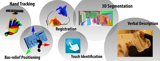
2.1. Hand Tracking
2.2. Point Cloud Registration
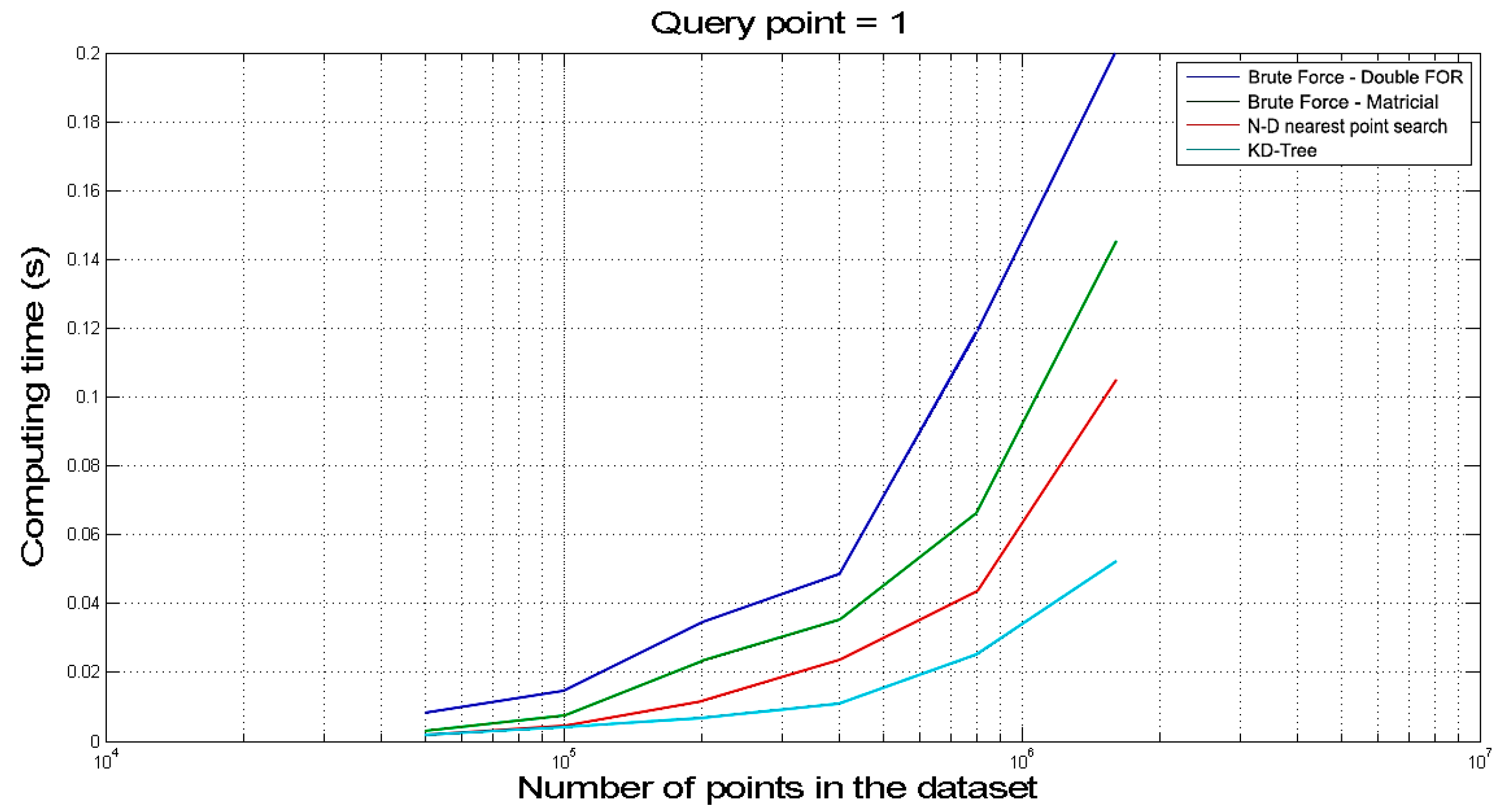
2.3. Distance Evaluation
3. System Layout
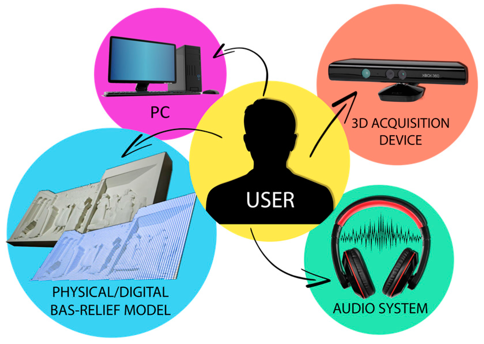
- (1)
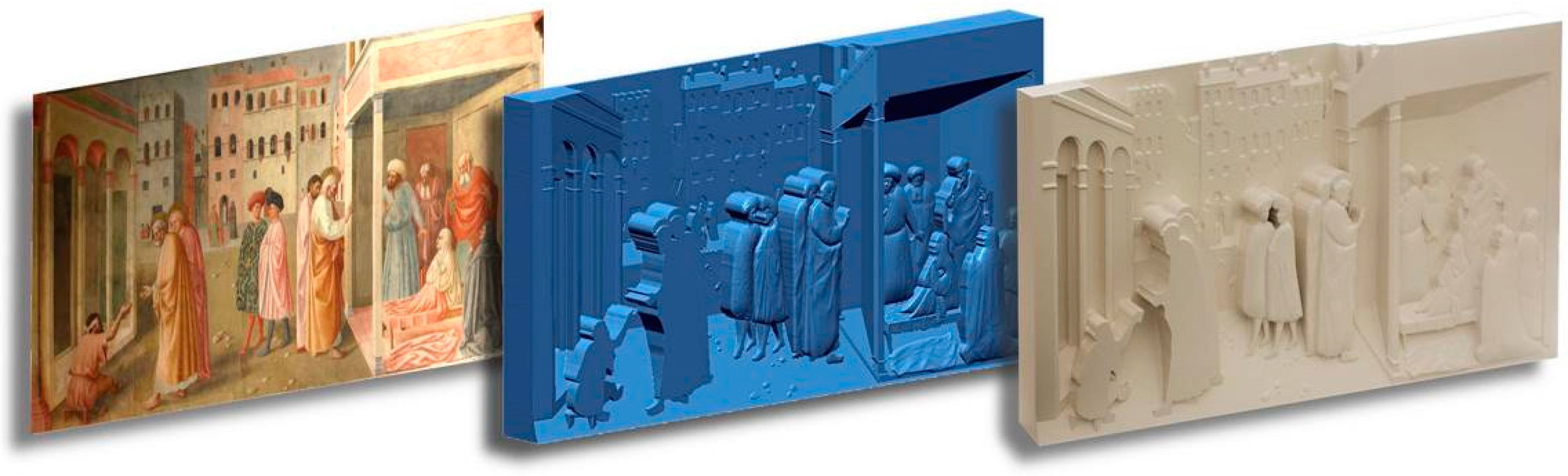
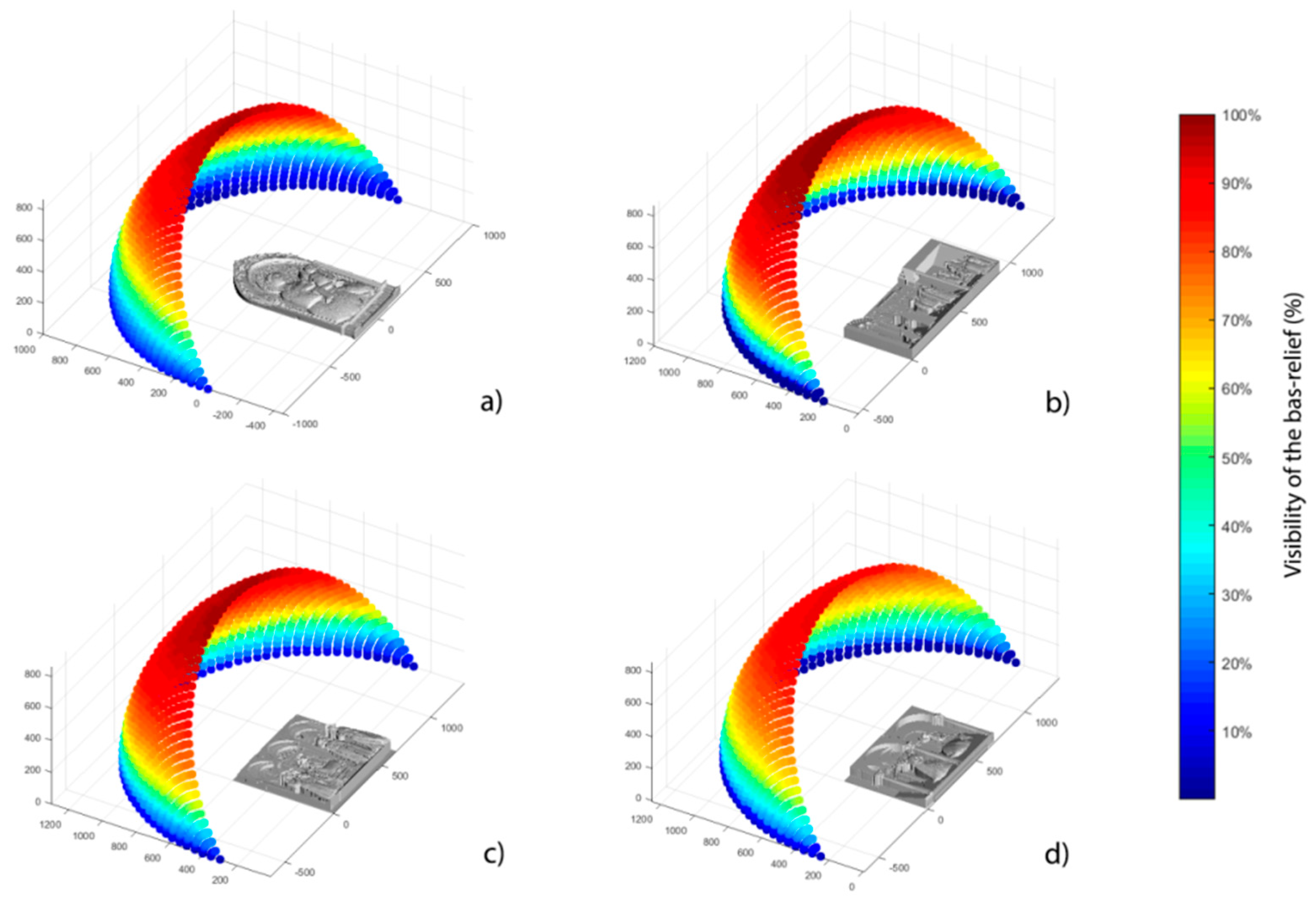
- A physical bas-relief to be explored by BP and its digital counterpart (e.g., a high-definition point cloud/polygonal model describing it).Even if, in principle, any kind of bas-relief could be used for developing the BES, in this work the used tactile models are the ones created by using the procedure described in [33], where shape from shading-based methods are devised to obtain both 3D polygonal models (e.g., STL) and a physical prototype of such a digital model starting from a shaded picture (for example a renaissance painting). In fact, by using such a procedure both the physical and digital 3D information are directly available. In any case, the proposed procedure can be applied to any kind of bas-relief (or in case the bas-relief is not allowed to be touched, to a replica) since the required initial information (polygonal model) can be easily achieved using a commercial 3D scanner.
- (2)
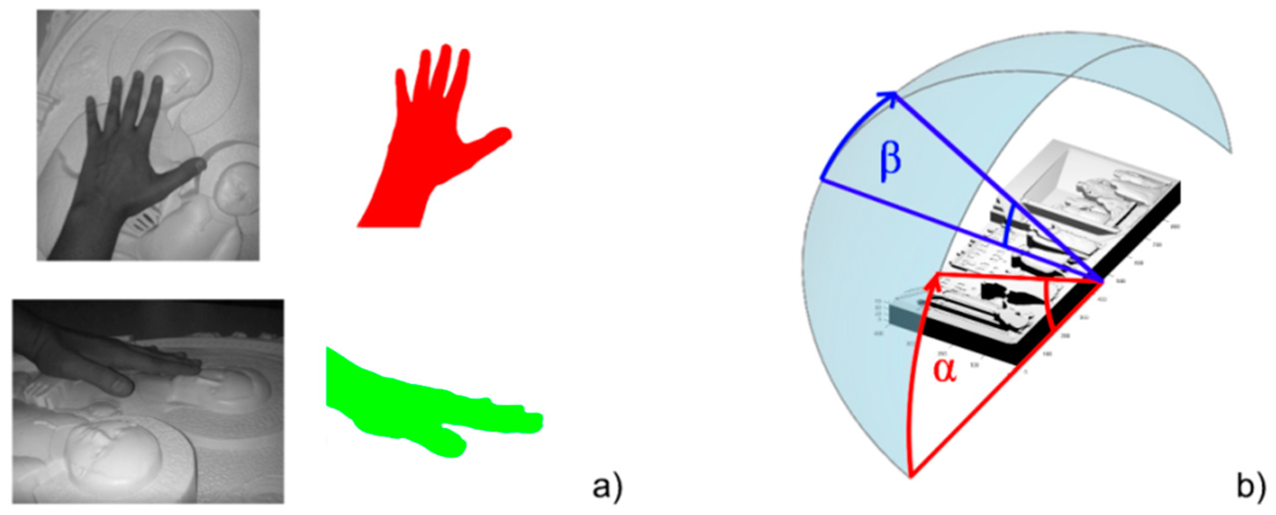
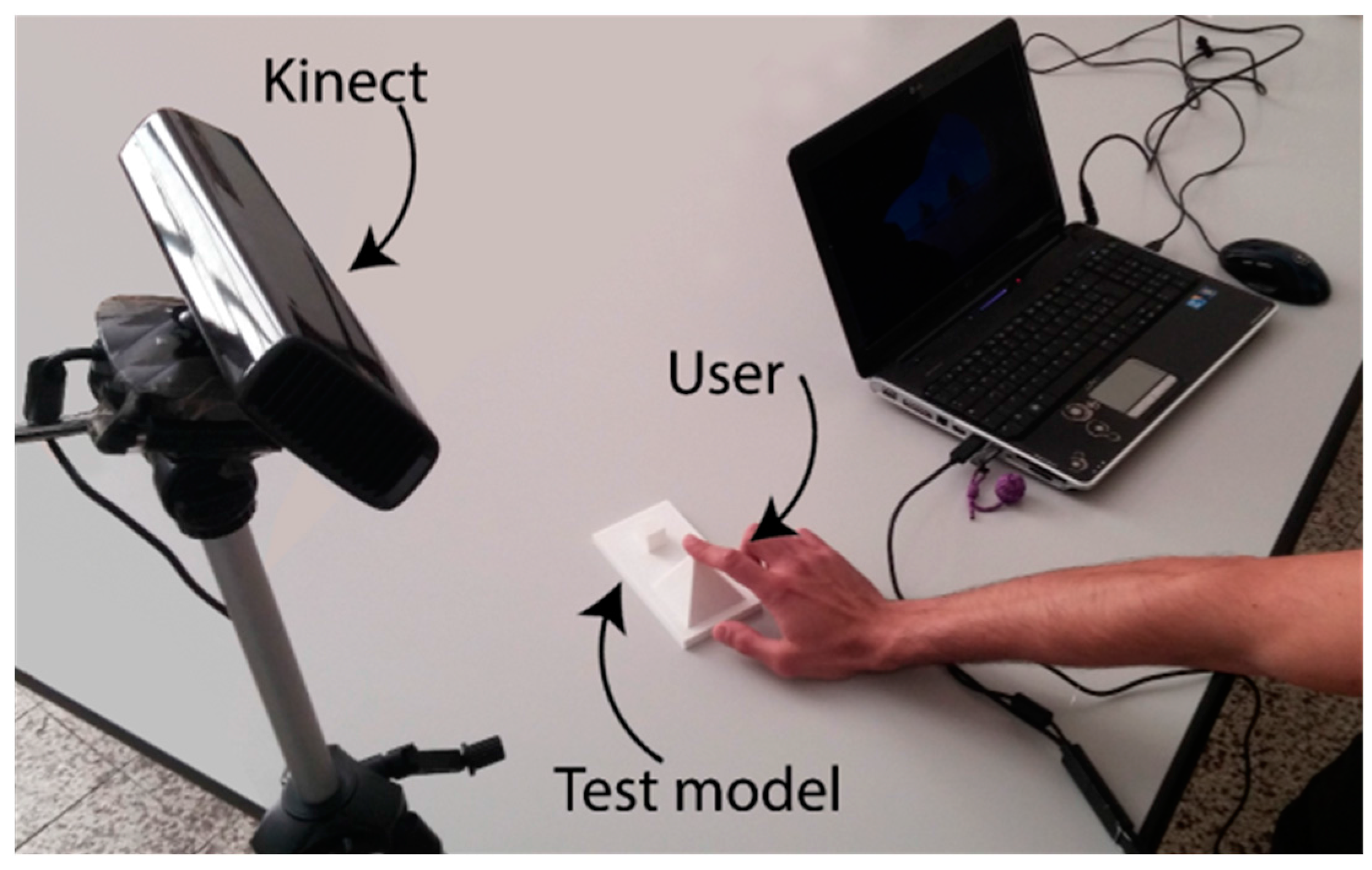
- A 3D acquisition device capable of (i) tracking the user hands and (ii) detecting the position of the physical bas-relief in its reference frame.The device used to build the system is the Microsoft Kinect®. As widely known, it consists of a projector-camera triangulation device furnished with a 43° vertical by 57° horizontal field of view that covers, at 1 m distance a visible rectangle of 0.8 m × 1.1 m. Such a field of view, to be considered as a plausible value for tracking according to [17], is required to cover the typical dimension of tactile bas-reliefs.
- (3)
- A PC workstation, in control of the whole BES.This element is responsible for the hand tracking, the required calculations (point clouds registration and distances computation, as previously described) and for the touch identification. The hardware needs to be equipped for GPU computing, and with hand tracking performances comparable with [17], to assure satisfying results.
- (4)
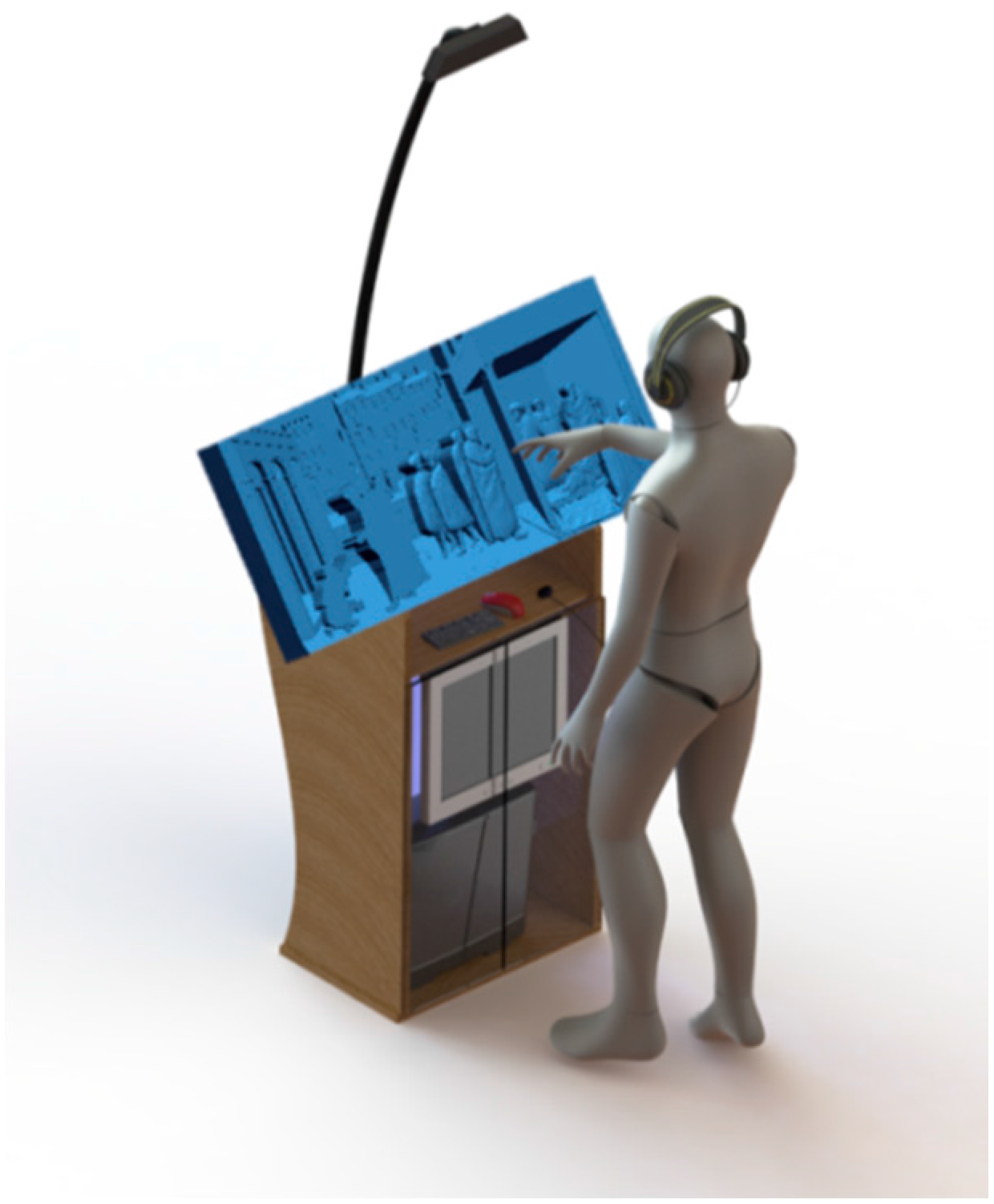
- An Audio system.Since the final outcome of the BES is, as already mentioned above, a verbal description of the scene and/or of touched objects or features, the system is equipped with headsets/headphones. Of course, to locate headsets could be difficult for unaccompanied BP; unfortunately, since the installation is specifically addressed to museum installations, the use of audio speakers could not represent a valid option.
4. Materials and Methods
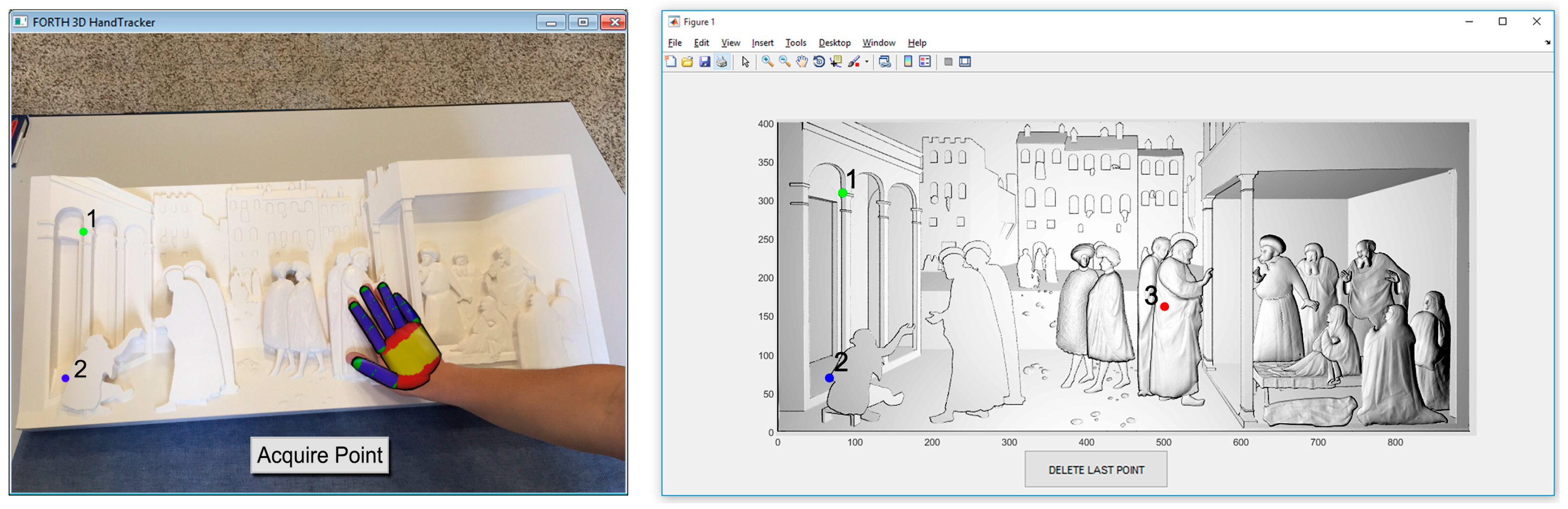
4.1. Hand Tracking
4.2. Bas-Relief Positioning
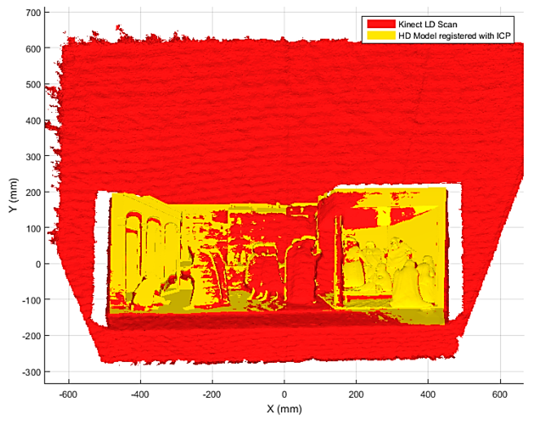
4.3. Registration
4.3.1. Coarse Registration
4.3.2. Fine Registration
4.4. Touch Identification
4.5. 3D Segmentation and Region Identification
4.6. Verbal Description
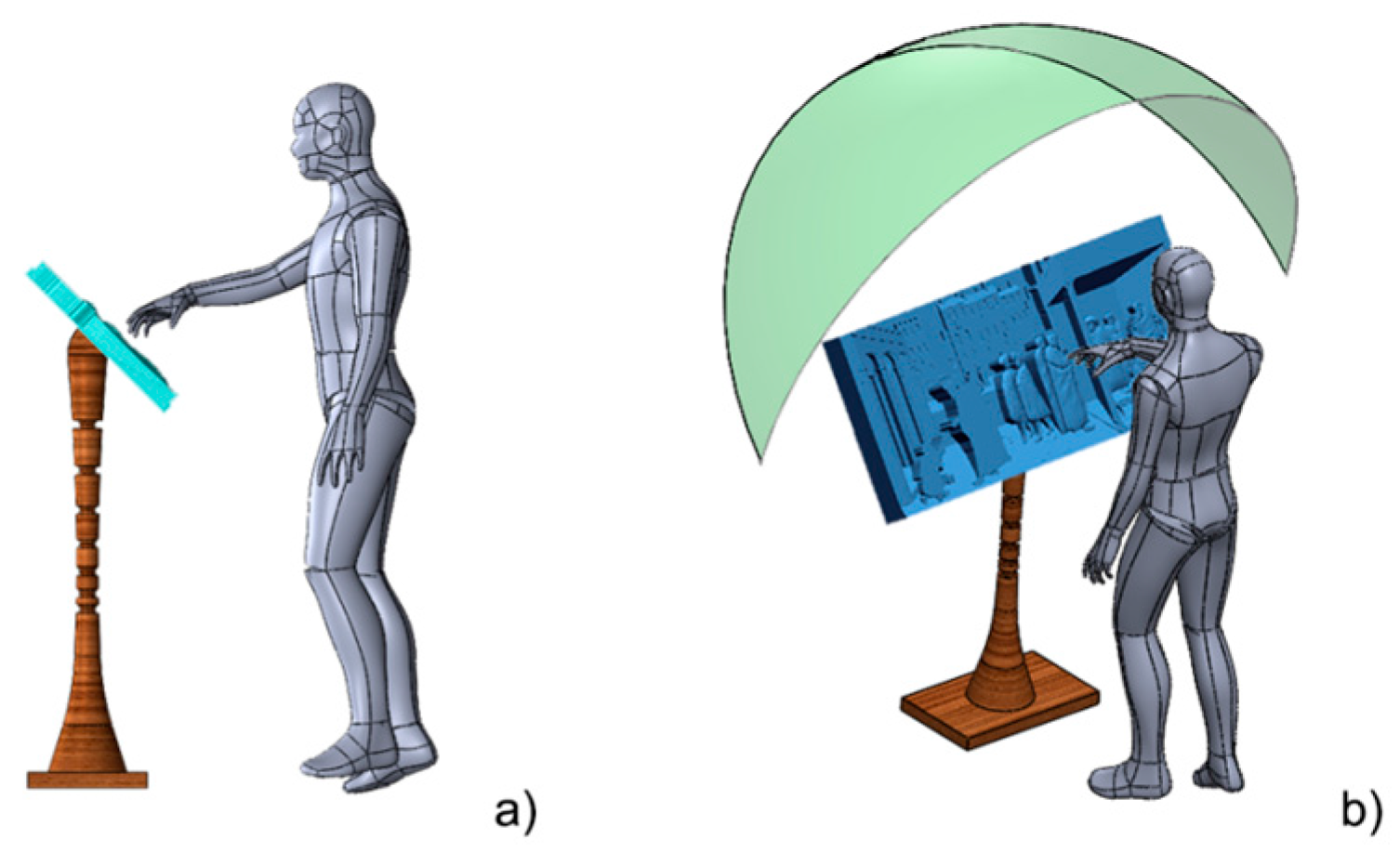
5. Physical Layout Alternatives
6. Discussion and Conclusions
Author Contributions
Conflicts of Interest
References
- Lahav, O.; Mioduser, D. Haptic-feedback support for cognitive mapping of unknown spaces by people who are blind. Int. J. Hum.-Comput. Stud. 2008, 66, 23–35. [Google Scholar] [CrossRef]
- Loiacono, E.T.; Djamasbi, S.; Kiryazov, T. Factors that affect visually impaired users’ acceptance of audio and music websites. Int. J. Hum.-Comput. Stud. 2013, 71, 321–334. [Google Scholar] [CrossRef]
- Song, W.; Belyaev, A.; Seidel, H.P. Automatic generation of bas-reliefs from 3d shapes. In Proceedings of the IEEE International Conference on shape modeling and applications, Lyon, France, 13–15 June 2007; pp. 211–214.
- Wang, M.; Chang, J.; Zhang, J.J. A review of digital relief generation techniques. In Proceedings of the 2nd International Conference on Computer Engineering and Technology (ICCET), Chengdu, China, 16–18 April 2010; pp. 198–202.
- Wang, R.; Paris, S.; Popović, J. 6D hands: Markerless hand-tracking for computer aided design. In Proceedings of the 24th Annual ACM Symposium on User Interface Software and Technology, Santa Barbara, CA, USA, 16–19 October 2011; pp. 549–558.
- Hayhoe, S. Arts, Culture and Blindness: Studies of Blind Dtudents in the Visual Arts; Teneo Press: Youngstown, NY, USA, 2008. [Google Scholar]
- Carfagni, M.; Furferi, R.; Governi, L.; Volpe, Y.; Tennirelli, G. Tactile representation of paintings: An early assessment of possible computer based strategies. In Progress in Cultural Heritage Preservation; Springer: Heidelberg, Germany, 2012. [Google Scholar]
- Buonamici, F.; Furferi, R.; Governi, L.; Volpe, Y. Making blind people autonomous in the exploration of tactile models: A feasibility study. In Universal Access in Human-Computer Interaction; Springer: Basel, Switzerland, 2015. [Google Scholar]
- Qin, H.; Song, A.; Liu, Y.; Jiang, G.; Zhou, B. Design and calibration of a new 6 DOF haptic device. Sensors 2015, 15, 31293–31313. [Google Scholar] [CrossRef] [PubMed]
- Arkenbout, E.; de Winter, J.; Breedveld, P. Robust hand motion tracking through data fusion of 5DT data glove and nimble VR Kinect camera measurements. Sensors 2015, 15, 31644–31671. [Google Scholar] [CrossRef] [PubMed]
- Airò Farulla, G.; Pianu, D.; Cempini, M.; Cortese, M.; Russo, L.; Indaco, M.; Nerino, R.; Chimienti, A.; Oddo, C.; Vitiello, N. Vision-based pose estimation for robot-mediated hand telerehabilitation. Sensors 2016, 16, 208. [Google Scholar] [CrossRef] [PubMed]
- Spruyt, V.; Ledda, A.; Philips, W. Robust arm and hand tracking by unsupervised context learning. Sensors 2014, 14, 12023–12058. [Google Scholar] [CrossRef] [PubMed]
- Boccanfuso, L.; O’Kane, J.M. CHARLIE: An adaptive robot design with hand and face tracking for use in autism therapy. Int. J. Soc. Robot. 2011, 3, 337–347. [Google Scholar] [CrossRef]
- Imagawa, K.; Lu, S.; Igi, S. Color-based hands tracking system for sign language recognition. In Proceedings of the 3rd IEEE International Conference on Automatic Face and Gesture Recognition, Nara, Japan, 14–16 April 1998; pp. 462–467.
- Farulla, G.A.; Russo, L.O.; Pintor, C.; Pianu, D.; Micotti, G.; Salgarella, A.R.; Camboni, D.; Controzzi, M.; Cipriani, C.; Oddo, C.M.; et al. Real-time single camera hand gesture recognition system for remote deaf-blind communication. In Augmented and Virtual Reality; Springer: Basel, Switzerland, 2014. [Google Scholar]
- Payá, L.; Amorós, F.; Fernández, L.; Reinoso, O. Performance of global-appearance descriptors in map building and localization using omnidirectional vision. Sensors 2014, 14, 3033–3064. [Google Scholar] [CrossRef] [PubMed]
- Oikonomidis, I.; Kyriazis, N.; Argyros, A.A. Efficient model-based 3D tracking of hand articulations using Kinect. BmVC 2011, 1, 1–11. [Google Scholar]
- Erol, A.; Bebis, G.; Nicolescu, M.; Boyle, R.D.; Twombly, X. Vision-based hand pose estimation: A review. Comput. Vis. Image Und. 2007, 108, 52–73. [Google Scholar] [CrossRef]
- De La Gorce, M.; Paragios, N.; Fleet, D.J. Model-based hand tracking with texture, shading and self-occlusions. In Proceedings of the IEEE conference on Computer Vision and Pattern Recognition, Anchorage, AK, USA, 23–28 June 2008; pp. 1–8.
- Stenger, B.; Thayananthan, A.; Torr, P.; Cipolla, R. Hand pose estimation using hierarchical detection. In Computer Vision in Human-Computer Interaction; Springer: Heidelberg, Germany, 2004. [Google Scholar]
- Esmin, A.A.; Coelho, R.A.; Matwin, S. A review on particle swarm optimization algorithm and its variants to clustering high-dimensional data. Artif. Intell. Rev. 2015, 44, 23–45. [Google Scholar] [CrossRef]
- Oikonomidis, I.; Kyriazis, N.; Argyros, A.A. Markerless and efficient 26-DOF hand pose recovery. In Proceedings of the 10th Asian Conference on Computer Vision, Queenstown, New Zealand, 8–12 November 2010; pp. 744–757.
- Oikonomidis, I.; Kyriazis, N.; Argyros, A.A. Full DOF tracking of a hand interacting with an object by modeling occlusions and physical constraints. In Proceedings of the IEEE International Conference on Computer Vision (ICCV 2011), Barcelona, Spain, 6–13 November 2011; pp. 2088–2095.
- Oikonomidis, I.; Kyriazis, N.; Argyros, A.A. Tracking the articulated motion of two strongly interacting hands. In Proceedings of the IEEE Conference Computer Vision Pattern Recognition, Providence, RI, USA, 16–21 June 2012; pp. 1862–1869.
- Poreba, M.; Goulette, F. A robust linear feature-based procedure for automated registration of point clouds. Sensors 2015, 15, 1435–1457. [Google Scholar] [CrossRef] [PubMed] [Green Version]
- Chen, L.; Hoang, D.; Lin, H.; Nguyen, T. Innovative methodology for multi-view point cloud registration in robotic 3D object scanning and reconstruction. Appl. Sci. 2016, 6, 132. [Google Scholar] [CrossRef]
- Salvi, J.; Matabosch, C.; Fofi, D.; Forest, J. A review of recent range image registration methods with accuracy evaluation. Image Vis. Comput. 2007, 25, 578–596. [Google Scholar] [CrossRef]
- Marichal, G.; Del Castillo, M.; López, J.; Padrón, I.; Artés, M. An artificial intelligence approach for gears diagnostics in AUVs. Sensors 2016, 16, 529. [Google Scholar] [CrossRef] [PubMed]
- Kibriya, A.M.; Frank, E. An empirical comparison of exact nearest neighbour algorithms. In Knowledge Discovery in Databases: PKDD; Springer: Heidelberg, Germany, 2007. [Google Scholar]
- Chiabrando, F.; Chiabrando, R.; Piatti, D.; Rinaudo, F. Sensors for 3D imaging: Metric evaluation and calibration of a CCD/CMOS time-of-flight camera. Sensors 2009, 9, 10080–10096. [Google Scholar] [CrossRef] [PubMed]
- Keller, J.M.; Gray, M.R.; Givens, J.A. A fuzzy K-nearest neighbor algorithm. IEEE Trans. Syst. Man Cybern. 1985, SMC-15, 580–585. [Google Scholar] [CrossRef]
- Piegl, L.A.; Rajab, K.; Smarodzinava, V.; Valavanis, K.P. Point-distance computations: A knowledge-guided approach. Comput.-Aided Des. Appl. 2008, 5, 855–866. [Google Scholar] [CrossRef]
- Furferi, R.; Governi, L.; Volpe, Y.; Puggelli, L.; Vanni, N.; Carfagni, M. From 2D to 2.5D ie from painting to tactile model. Graph. Models 2014, 76, 706–723. [Google Scholar] [CrossRef]
- Besl, P.J.; McKay, N.D. Method for registration of 3-D shapes. In Proceedings of the SPIE 1611, Sensor Fusion IV: Control Paradigms and Data Structures, Boston, MA, USA, 12–15 November 1991.


| Number of Tests | Positive Touch Identifications | False Negatives | False Positives |
|---|---|---|---|
| 100 | 74 | 18 | 8 |
© 2016 by the authors; licensee MDPI, Basel, Switzerland. This article is an open access article distributed under the terms and conditions of the Creative Commons Attribution (CC-BY) license (http://creativecommons.org/licenses/by/4.0/).
Share and Cite
Buonamici, F.; Carfagni, M.; Furferi, R.; Governi, L.; Volpe, Y. Are We Ready to Build a System for Assisting Blind People in Tactile Exploration of Bas-Reliefs? Sensors 2016, 16, 1361. https://doi.org/10.3390/s16091361
Buonamici F, Carfagni M, Furferi R, Governi L, Volpe Y. Are We Ready to Build a System for Assisting Blind People in Tactile Exploration of Bas-Reliefs? Sensors. 2016; 16(9):1361. https://doi.org/10.3390/s16091361
Chicago/Turabian StyleBuonamici, Francesco, Monica Carfagni, Rocco Furferi, Lapo Governi, and Yary Volpe. 2016. "Are We Ready to Build a System for Assisting Blind People in Tactile Exploration of Bas-Reliefs?" Sensors 16, no. 9: 1361. https://doi.org/10.3390/s16091361