1. Introduction
Current fiber optic gyroscopes (FOGs) have very good performance [
1], but inevitably they still have large Shupe effects, Faraday effects and radiation effects due to the fact that conventional silica fiber is very sensitive to these environments. Photonic bandgap fibers (PBFs), a novel kind of fiber in which the light travels not in a conventional silica core but in an air core [
2,
3,
4], have attracted considerable interest owing to their unique optical properties such as significantly lower nonlinear coefficients and especially, their improved adaptability to temperature, magnetic fields and radiation in comparison with the properties of silica fibers [
5,
6].
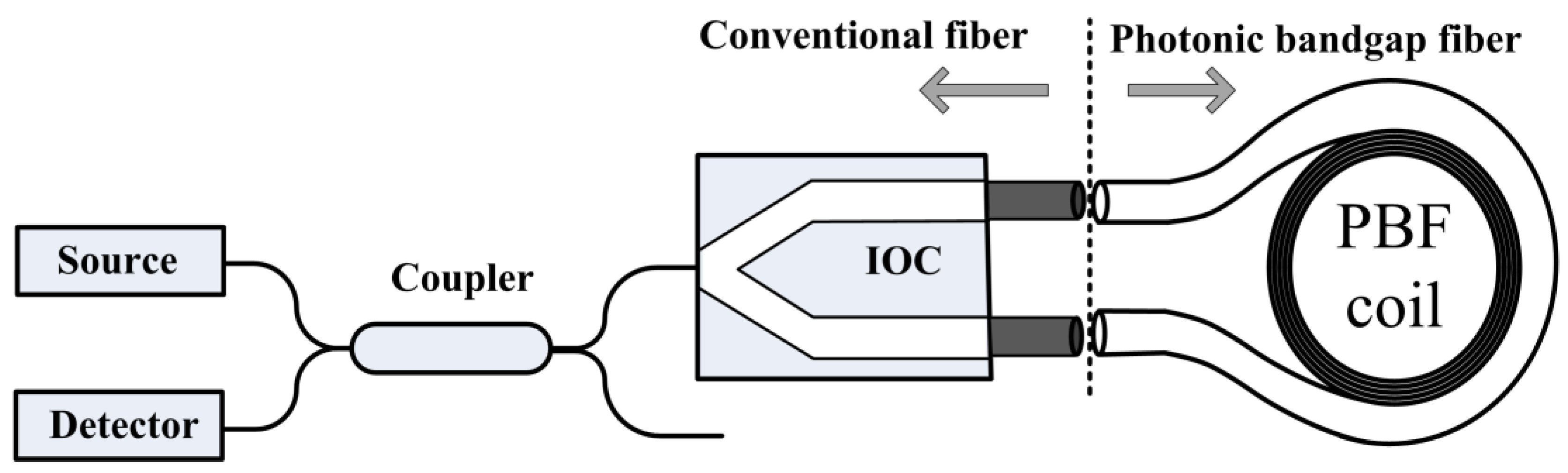
A photonic bandgap fiber optic gyroscope (PBFOG), as illustrated in
Figure 1, consists of a broad-spectrum source, a coupler, an integrated optic chip (IOC), and a PBF coil [
7,
8]. A previous study [
9] has reported reductions in the errors induced by the Kerr effect (>170), Shupe effect (~6.5), and Faraday effect (>20) in a PBFOG when compared with the corresponding error values of a conventional FOG. Therefore, the PBFOG represents a substantially improvement of these key properties compared to a FOG, and it has excellent prospects, but as a new kind of FOG, it definitely exhibits some different errors and noises from those which are normally observed in a traditional FOG owing to the use of the PBF. References [
7,
8] have investigated shot noise, backscattering noise which is defined as the error due to coherence interference between the backscattered waves and primary waves and which also exists in resonant fiber optic gyroscopes using an air-core fiber [
10,
11], electronic noise, and reflection-induced intensity noise; further, the polarization non-reciprocity error has also been investigated [
12]. In this study, for the first time to the best of our knowledge, we find and investigate the backward secondary-wave coherence (BSC) error, which is defined as a bias error caused in the PBFOG by interference between back-reflection-induced and backscatter-induced secondary waves.
2. Theoretical Analysis
In the PBFOG, the pigtails of the IOC are conventional fibers that have a Ge-doped SiO
2 core, but the coil comprises a commercially available 7-cell air-core PBF with hexagonal air holes triangularly arranged in the cladding [
12]. According to the measurement results in our previous study [
13], a strong reflection inevitably occurs at the two fusion splicing points between the PBF coil and the IOC pigtails. Both back-reflection-induced secondary waves have very large magnitudes (only about 3–10 times smaller than that of primary waves for a 300-m coil composed of a PBF with a loss of 20 dB/km). Obviously, those back-reflection-induced secondary waves produce an offset at the detector and add intensity-type noise because the coherence length of the broad-spectrum source is always considerably less than the path mismatch length between the two IOC pigtails, and thus, there is no interference between these two sets of secondary waves [
7,
9]. However, we found that the strong back-reflection-induced secondary waves at one fusion splicing point inevitably interfere with the backscatter-induced secondary waves within the other pigtail, thereby causing a BSC error. This BSC error is a phase-type error that does not exist in a conventional FOG, and it seriously affects the PBFOG performance.
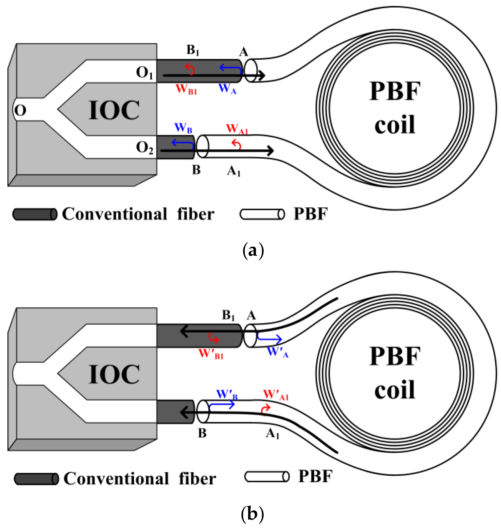
As illustrated in
Figure 2a, before the primary-wave (black arrows) output from the IOC enters the PBF coil, secondary waves (W
A and W
B) are generated owing to the strong back-reflection at fusion splicing points A and B. W
A has an optical path of
L(W
A) =
nIOC|OO
1| +
nSiO2|O
1A| from the common input/output end O.
nIOC and
nSiO2 is, respectively, the refractive index of the IOC and conventional fiber. It is well known that the backscattering is randomly distributed along the fiber, and each backscattering point causes a secondary wave, but not all of those backscattering-induced secondary waves are able to interfere with W
A, because it is the broad-spectrum light in the optical circuit and the interference intensity is maximum when the optical path difference (OPD) is 0, but decreases dramatically and rapidly as the OPD increases [
14]. Therefore, if a secondary wave W
A1 induced by the backscattering at point A
1 has an optical path of
L(W
A1)=
nIOC|OO
2| +
nSiO2|O
2B| +
nair|BA
1|from the common input/output end O and
L(W
A1) =
L(W
A), then the interference occurs between W
A and W
A1 and the intensity is maximum that is given by the first term in:
which equation describes the summed intensity (as detected by the detector) of all the interference phenomena involved (that is,
IBSC). Here
nair is the refractive index of the PBF. In Equation (1),
Iin denotes the light intensity output from the IOC. Further, α
in, α
splicing, and α
coil represent the losses at the input channel (from the IOC pigtail to detector), fusion splicing at points A and B, and PBF coil, respectively. The typical values of α
in, α
splicing, and α
coil are ~8 dB, ~1.5 dB and ~6.6 dB for a 300-m PBF coil, respectively. Parameters
RA and
RB represent the back-reflection coefficients at points A and B, respectively. Similarly,
RA1 and
RB1 represent the backscattering coefficients at points A
1 and B
1, respectively. Parameters
φ1,
φ2,
φ3, and
φ4 denote the random phases between the two secondary waves involved in the interference.
Фm is the modulation phase.
Interference between W
B and W
B1 can similarly be examined, and the resulting interference intensity is given by the second term in Equation (1). On the other hand, as illustrated in
Figure 2b, when the primary-wave output from the PBF coil after propagating through the coil once, backward secondary waves (W′
A, W′
B, W′
A1, W′
B1) arise, and interference can also occur between W′
A and W′
A1, W′
B and W′
B1 with the intensities given by the last two terms in Equation (1). In fact, there also exist other backward secondary waves that propagate over multiple loops; however, their contribution to the BSC error is very small, and the relevant terms have been neglected in Equation (1).
In the standard FOG operation, a square wave with eigenfrequency
fτ and amplitude of ±π/8, and a sawtooth wave with amplitude π are added and applied to the IOC to modulate primary waves for coherence detection and closing-loop operation [
14]. The demodulation value of the interference intensity between the primary waves indicates the angle velocity of the FOG. The back-reflection-induced and backscatter-induced secondary waves also propagate through the IOC, and therefore, these waves are also modulated by the square and sawtooth waves; thus, the modulation phase
Фm in Equation (1) includes two parts: the square-wave-induced phase (
Фm_SQ) and the sawtooth-wave-induced phase (
Фm_SA). Because the secondary waves propagate twice through the same branch of the IOC,
Фm_SQ has an amplitude of ±π/2 and frequency of
fτ, and
Фm_SA has an amplitude of 4π.
According to the theory of coherence detection, because
Фm_SQ has the same modulation frequency (
fτ) as that of the primary waves, the demodulation value of
IBSC cannot be separated from the angle velocity of the FOG which is the demodulation result of the primary waves’ interference, thus leading to a bias error (namely, the BSC error) [
14]. On the other hand,
Фm_SA leads to BSC error’s variation with the sawtooth wave, and there are two complete periods when the sawtooth wave changes from 0 (rad) to π (rad). Under extreme conditions, the maximum BSC error is given by:
where
D and
L represent the diameter and fiber length of the coil, respectively,
λ the wavelength, and
c the velocity of light.
3. Experimental Results
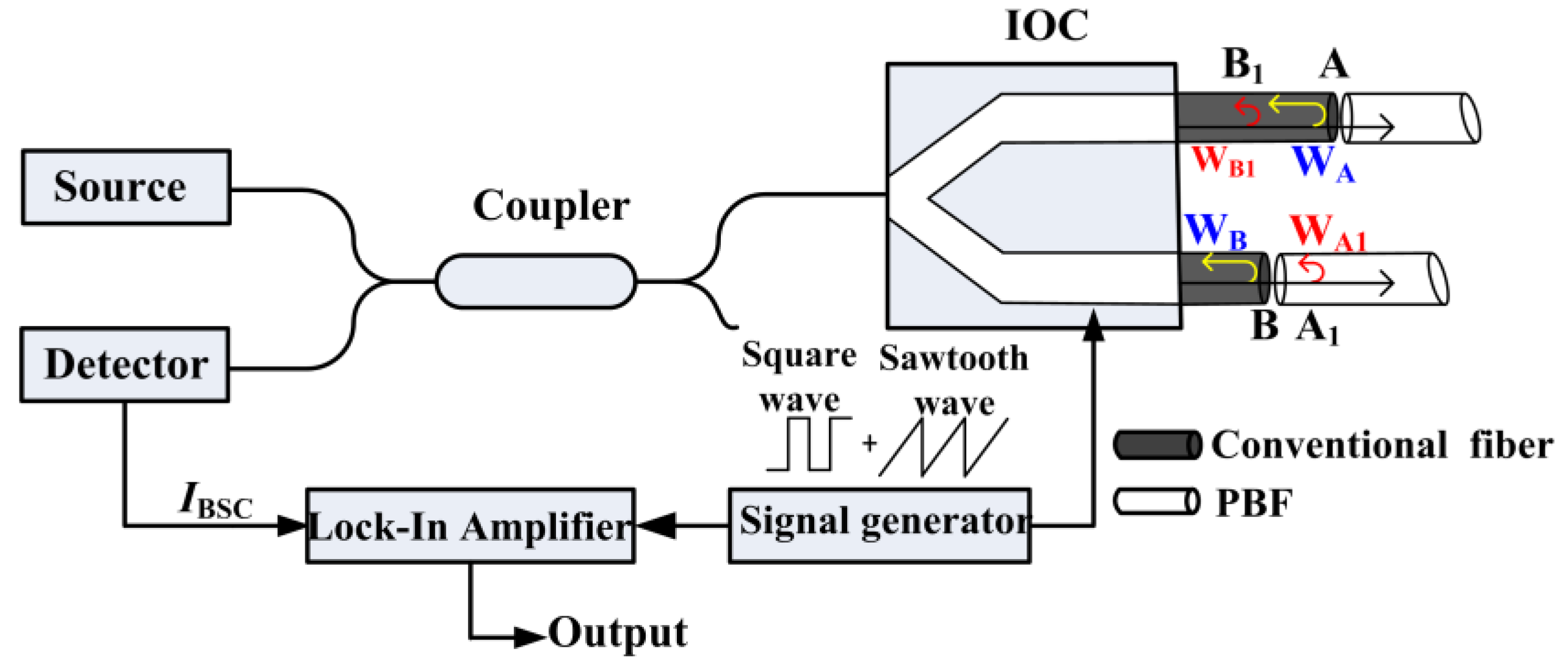
To verify the existence of the BSC error and measure its magnitude in a practical FOG, we promoted a method and established the corresponding experimental setup, as illustrated in
Figure 3, where the light launched from an amplified spontaneous emission (ASE) source enters the IOC through a single-mode fiber coupler, and it travels backward to the detector owing to the back-reflection and backscattering. The ASE source has a power of ~5 mW and the IOC is a proton-exchanged LiNbO
3 circuit with the half-wave voltage of ~5 V. In fact, the setup mainly aims at determining the first two terms in Equations (1) or (2), which are the dominant BSC error terms. Moreover, our setup has a configuration that is nearly identical to the FOG configuration; square and sawtooth waves are applied to the IOC, and a lock-in amplifier is used to demodulate the interference intensity (
IBSC) at the detector so as to better simulate the actual FOG operation. The one difference in our case is that two lengths of PBFs (and not a PBF coil) are connected to the two IOC pigtails to eliminate interference between the primary waves whose demodulation value cannot be separated from the measurement results. From the aspect of BSC error determined by the first two terms in Equation (1), this difference does not matter, because this part of the BSC error does not depend on the subsequent PBF coil. Considering the IOC’s half-wave voltage and the signal generator’s single-end output, we set the square wave frequency to 500 kHz with an amplitude of ±1.25 V, and the sawtooth wave is set to vary from 0 V to 10 V. Based on the analysis mentioned above, the demodulation result of
IBSC should have two sinusoidal periods when the sawtooth wave changes from 0 V to 10 V, and its peak-to-peak value can be easily resolved, which value directly reflects
Iinα
splicing(
RARA1)
1/2 or
Iin(
RBRB1)
1/2 or their sum according to which splicing point exists in the system.
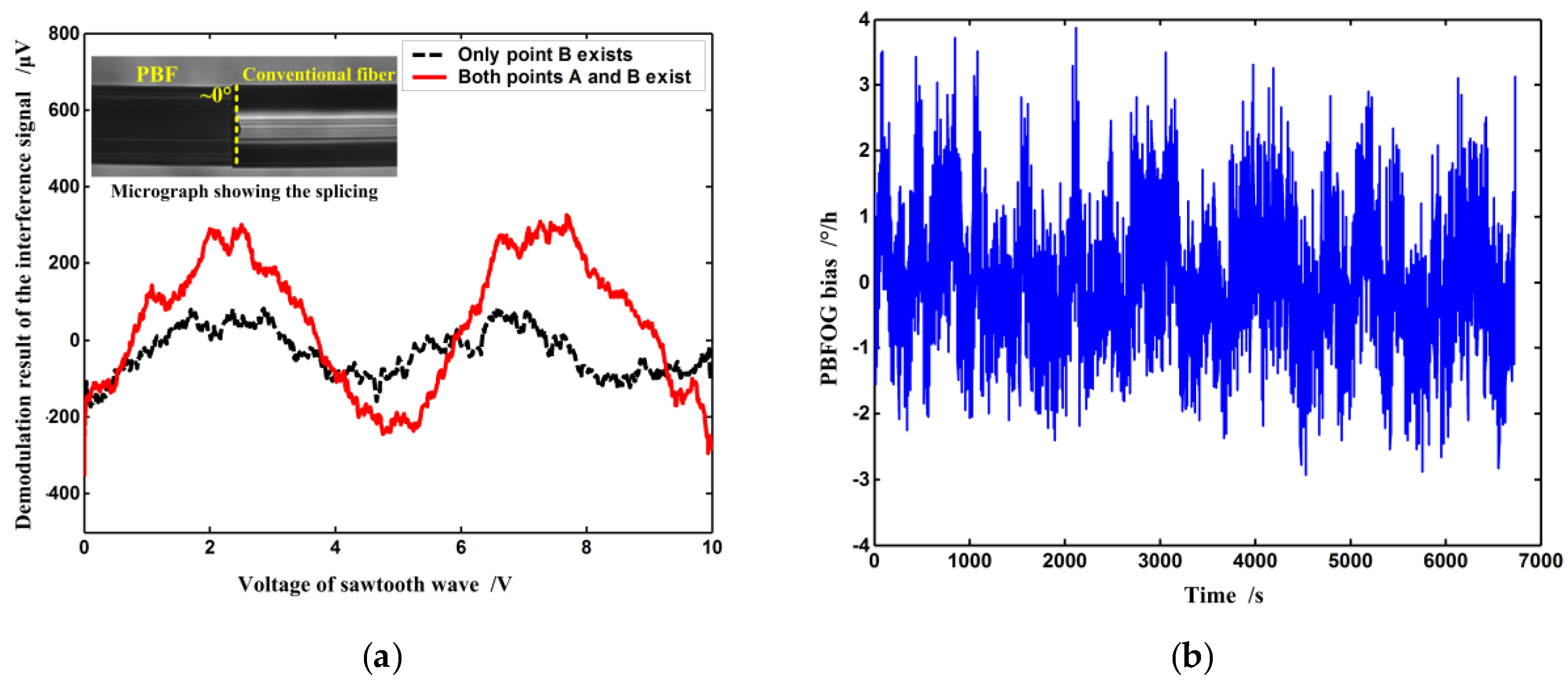
First, a length of PBF is normally connected to the IOC pigtail at point B through fusion splicing. The micrograph of the splicing between the PBF and IOC pigtail is shown in the inset in
Figure 4a. Since it is 0° splicing, the secondary wave W
B is generated and its interference with W
B1 occurs simultaneously. The lock-in amplifier’s output after demodulation of the interference intensity
IBSC is described by the dashed curve in
Figure 4a where the fixed bias induced by such phenomena as Earth rotation has been taken out. Obviously, the output varies with the voltage of the sawtooth wave, and there are two periods when the voltage changes from 0 V to 10 V, a result that agrees well with the abovementioned analysis. The peak-to-peak value of the output is ~130 μV, which implies that (
RBRB1)
1/2 ~3.5 × 10
−7, and therefore, the maximum BSC error in this case is ~1.36°/h according to Equation (2) for a 300-m PBF coil with a diameter of 10 cm. Next, a second PBF is also similarly connected to the other IOC pigtail at point A by fusion splicing. The resulting output is described by the solid line in
Figure 4a. The peak-to-peak value of the output is ~450 μV, and consequently, the total maximum BSC error is ~4.7°/h according to Equation (2). The experimental results indicate that interference between W
A and W
A1 contributes more to the BSC error than that between W
B and W
B1, which can be explained by the fact that the backscatter coefficient in the PBF is higher than that in conventional fibers [
15].
In a real closed-loop PBFOG, the BSC error can seriously affect the bias stability. Bias stability is defined as the random variation in bias as computed over specified finite sample time and averaging time intervals according to IEEE standard [
16]. The secondary waves W
A and W
A1, W
B and W
B1 are not reciprocal, because they propagate along different optical paths (see
Figure 2a). The environment (temperature, vibration, and so on) definitely has different influences on different optical paths, as a result, their phase differences (
φ1,
φ2) are random environment-dependent variables. When those secondary waves interfere, their interference intensities and the induced BSC error would also vary randomly, so the PBFOG bias becomes unstable if it includes this error. In order to verify the BSC error’s influence on PBFOG bias stability, a real PBF coil, instead of the two lengths of PBFs, is connected to the IOC pigtails with normal fusion splicing on the basis of the experimental setup in
Figure 3, and forms a complete PBFOG. A signal-processing electronic circuit substitutes the lock-in amplifier and signal generator to implement the digital closing-loop operation in the PBFOG [
14]. The test result of the PBFOG bias is shown in
Figure 4b, where the fixed bias induced by such as earth rotation has also been taken out. The test result indicates that the bias remarkably fluctuates and the corresponding bias stability is ~0.75°/h (standard deviation, 10 s integration time).
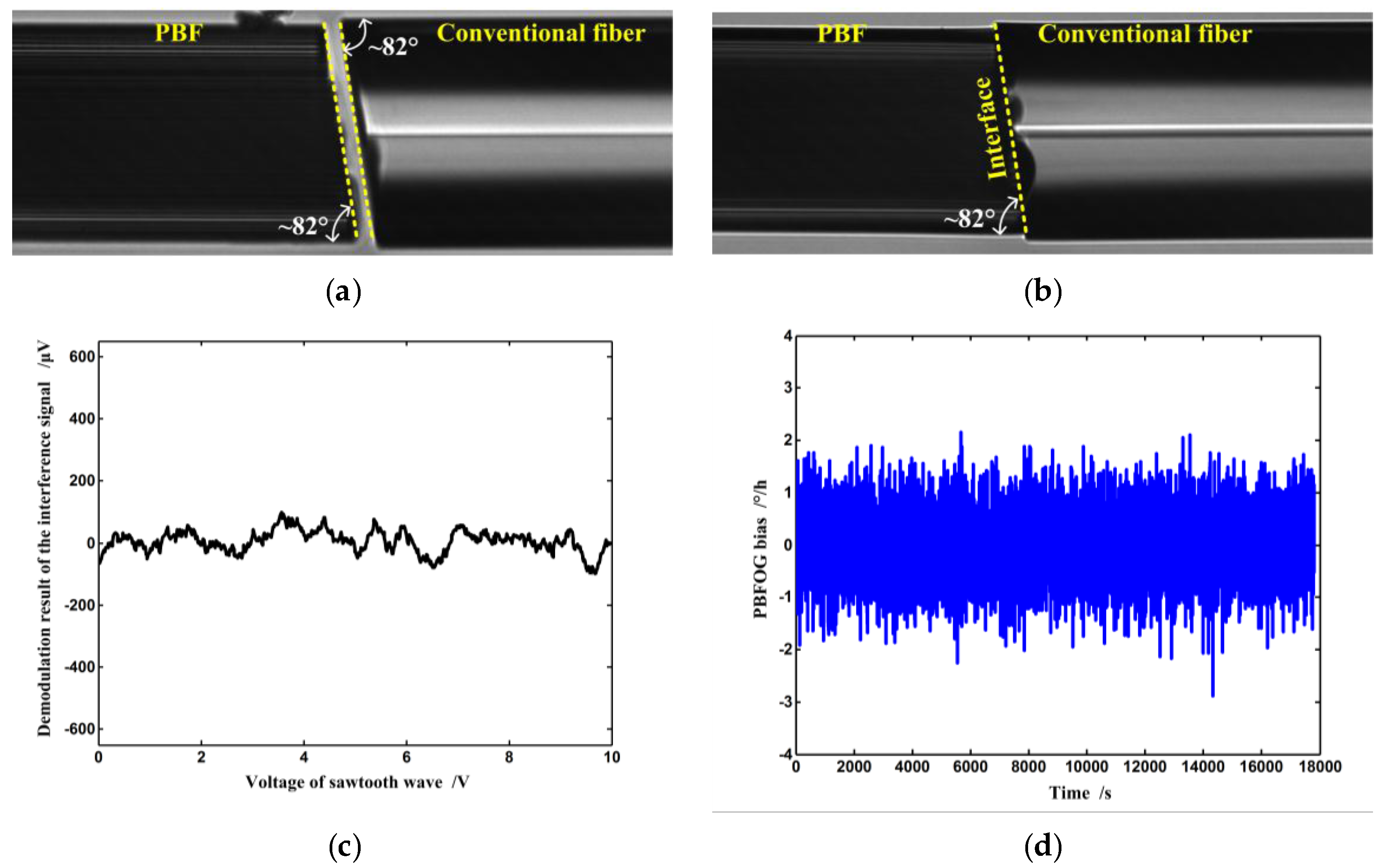
Although backscatter within the fiber cannot be eliminated, back-reflection can be reduced through an angled fiber end face in fiber termination in order to suppress the BSC error. A tilted angle of 8° is a commonly used value for conventional fiber and it is often applied in fiber connectors to suppress back-reflection [
17]. Although a larger cleavage angle can further reduce the back reflection, this will come at the cost of increased splicing loss, so in the experimental FOG, both the pigtails of the IOC and PBF coil are cleaved at a tilted angle of ~8° to guarantee both the suppression of back-reflection at the interface and the proper fusion splicing loss, as shown in
Figure 5a [
7,
9,
10,
11,
18]. After fusion splicing, according to the test results, the reflectance at the interface (see
Figure 5b) is reduced from greater than −20 dB to ~−54 dB, so the intensity of both W
A and W
B decreases to be negligible compared to the primary waves. Under this condition, the BSC error is also negligible according to the experimental result, as illustrated in
Figure 5c that gives the test result of the BSC error; the corresponding PBFOG performance is shown in
Figure 5d. Obviously, when the BSC error is suppressed, the bias stability is dramatically improved to ~0.4°/h (standard deviation, 10 s integration time). Therefore, we can conclude that the BSC error is an important bias error source that seriously affects the PBFOG performance, and it has to be addressed before any practical application of the PBFOG is considered.

