Second-Law Analysis to Improve the Energy Efficiency of Screw Liquid Chillers

Department of Energy and Refrigerating Air-Conditioning Engineering, National Taipei University of Technology, Taipei 10608, Taiwan
Entropy 2010, 12(3), 375-389; https://doi.org/10.3390/e12030375
Submission received: 1 January 2010
/
Revised: 2 February 2010
/
Accepted: 1 March 2010
/
Published: 4 March 2010
(This article belongs to the Special Issue Exergy: Analysis and Applications)
Abstract
:This work applies the second-law analysis of thermodynamics to quantify the exergy destruction of the components of screw liquid chiller, and to identify the potential for each component to contribute to improve the overall energy efficiency of the system. Three screw liquid chiller units were built to demonstrate the feasibility of the model presented herein. Unit A was a 100 RT water-cooled screw liquid chiller. Unit B was modified from Unit A by switching the old condenser for a new one with a greater heat transfer, and Unit C was modified from Unit B by exchanging the compressor for a more efficient one. The results indicate that the compressor has the largest potential to improve energy efficiency, followed in order by the condenser, and then the evaporator. The second law analysis may help engineers to focus on the components with higher exergy destruction and quantify the extent to which modifying such components can influence, favorably or unfavorably, the performance of other components of the screw liquid chiller.
1. Introduction
Vapor-compression liquid chillers have been commonly used to cool water, brine and other secondary coolants, in commercial and industrial air-conditioning or refrigeration systems. The primary components of a vapor-compression liquid chiller include a compressor and its driver, a condenser, a throttling device, a liquid cooler (evaporator), and a control system. Specifications of the energy efficiency of liquid chillers typically involve the coefficient of performance (COP), the energy efficiency ratio (EER) and the input energy ratio (kW/RT) as indices. All such approaches to evaluating the energy efficiency of liquid chillers are based on the first law of thermodynamics. The measured quantity is thus called first-law efficiency. However, the first law of thermodynamics states the conservation of energy and the transformation of energy from one form to another. Preserving the quality of energy and increasing the energy efficiency of liquid chillers are major concerns to engineers, and the second law provides the necessary means to determine the quality as well as the extent of degradation of energy during a process. The energy efficiency of a liquid chiller is a consequence of the destruction of available energy (or exergy) contributed by every system component, so the second-law analysis, incorporating the first and second laws of thermodynamics, directly evaluates the potential to improve the efficiency of liquid chillers.
Recent studies have increasingly applied the second-law analysis in the fields of refrigeration, air-conditioning and heat pump systems [1,2,3,4,5,6,7,8,9,10,11,12,13]. Second-law analysis can be divided into exergy (or availability) and irreversibility analyses. The former addresses the conversion and loss of exergy while the latter concern the entropy generation and irreversibility. Bejan [14] detailed fundamental theories and concepts. Liang and Kuehn [1] performed irreversibility analysis on data obtained from a R-22 reciprocating water-cooled liquid chiller with a cooling capacity of 7.56 kW in a steady state. The analytical results show that the percentages of the irreversibility associated with the components were, compressor 44.41%, condenser 27.11%, evaporator 18.13%, expansion valve 4.06%, suction line 4.44% and discharge line 1.85%. ASHRAE [8] illustrated the second-law analysis of an R-22 reciprocating, air-cooled, direct expansion refrigerator, with a cooling capacity of 7.0 kW. The results indicated that the percentages of the total irreversibility associated with the components were compressor 46%, condenser 18%, expansion valve 18%, evaporator 9%, discharge line 5%, suction line 3% and liquid line 0%. The results differ from those of Liang and Kuehn [1].
Brian et al. [9] applied the second law analysis to quantify the irreversibility of components in a household freezer with a volume of 18 ft3 and an air-conditioner with a capacity of 10.5 kW. They identified the potential of every component to improve the overall energy efficiency of the system. Specifically, their analysis revealed that the percentage irreversibilities associated with the components of the freezer followed the order of the compressor, the condenser and then the evaporator. This sequence differs from that obtained for the air-conditioner, for which the evaporator ranked first, followed by the condenser and the compressor.
Yumrutaş et al. [11] used exergy analysis to develop a theoretical model to investigate the effects of the evaporating and condensing temperatures on the pressure drop, the exergy destruction, the second-law efficiency and the coefficient of performance (COP) of a vapor compression refrigeration cycle. The results revealed that the two design parameters of evaporating and condensing temperature strongly affected the exergy destructions associated with the evaporator and the condenser, the second-law efficiency and the COP of the cycle, but only weakly influenced the exergy destructions in the compressor and the expansion valve. Reducing the difference between the temperature of the evaporator and that of the refrigerated space, and between the temperature of the condenser and that of the outside air can reduce the total loss of exergy and simultaneously improved the COP and second-law efficiency.
The works cited above shows that the application of the second-law analysis to commercial screw liquid chillers is still lacking. The main goal of this study is to develop a methodology, based on second-law analysis, to be applied to evaluate the irreversibility of the components of a screw liquid chiller, and to identify the potential for each component to contribute to the energy efficiency of the overall system. Three screw liquid chillers, units A, B and C, are built to confirm the model developed herein. Unit A is selected as a baseline unit in this work. It is a liquid chiller with a nominal cooling capacity of 100 tons and screw type compressor; it has a direct-expansion plate-type evaporator and a water-cooled, shell-and-tube type condenser. Unit B is the chiller modified from unit A by replacing the old condenser with a new one with enhanced heat-transferring cooper tubes, and Unit C is modified from Unit B by replacing the compressor with a more efficient one. Comparisons were made to evaluate the improvement by second-law analysis.
Engineers could use the analytical method presented in this study to quantify the irreversibility of components in their liquid chiller designs and provide a clear direction in which to increase the system energy efficiency of a liquid chiller. The analysis also provides insights into how efficient components influence the potential payoff of improving another component.
2. Second-Law Analysis
2.1. Thermodynamic Modeling
The actual vapor-compression refrigeration cycle is the most extensively employed cycle in liquid chillers. This actual cycle consists of several components, such as a compressor, a condenser, an expansion device, an evaporator and connecting pipelines. It differs from the ideal vapor-compression refrigeration cycle in many ways, mostly due to the irreversibility associated with various components. Two common sources of irreversibility in the actual refrigeration cycle are fluid friction, which causes falls in pressure, and heat transfer across a finite temperature difference.
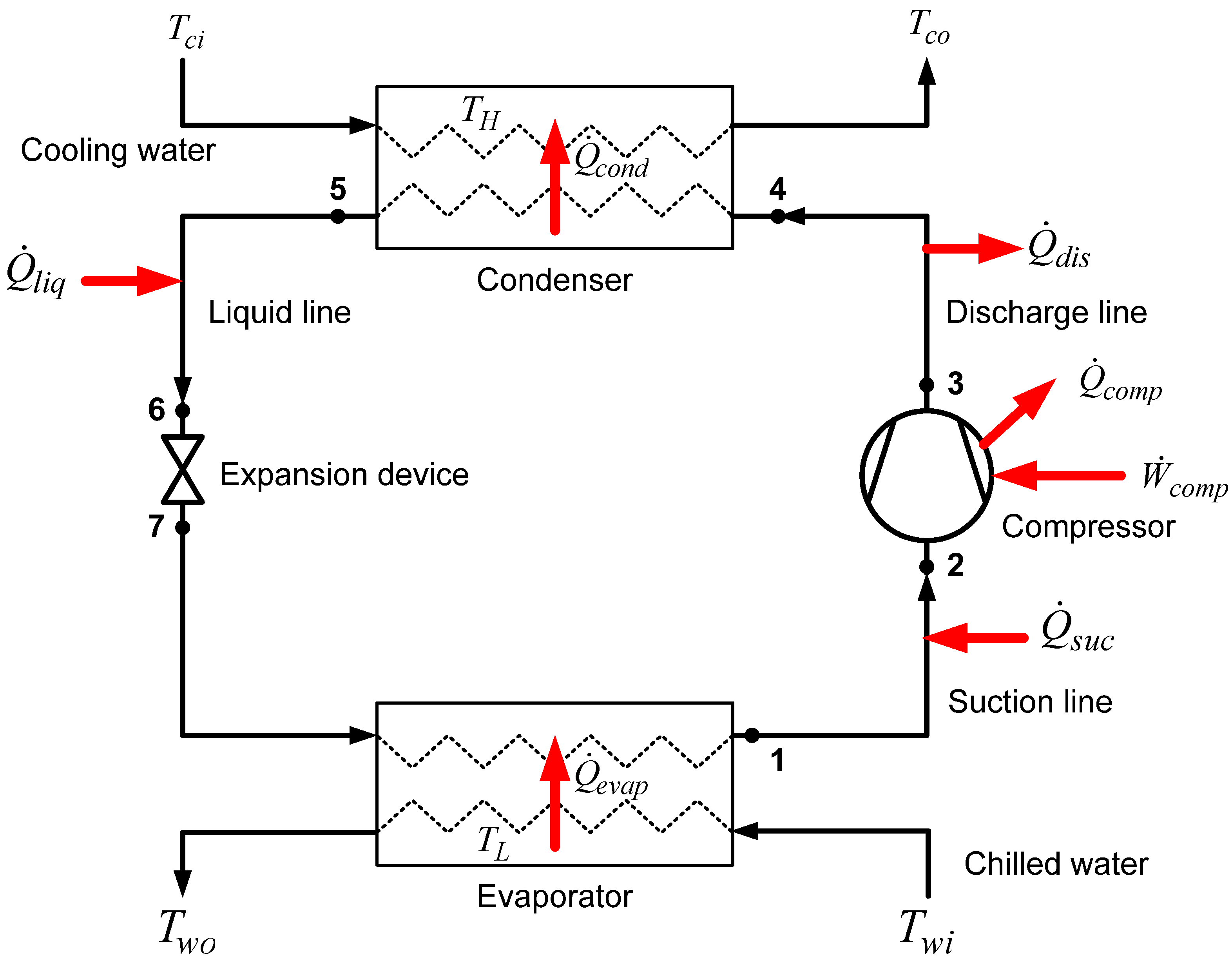
Consider each component in a real vapor-compression cycle, as indicated in Figure 1, as a control volume that undergoes a steady-flow process. The first and second laws of thermodynamics for a steady-flow process are as follows [14]:
The irreversibility (or exergy destruction) of each process can be determined using the Guoy-Stodola relation:
The energy and entropy balance can be simplified by making further assumptions for each component. The evaporator, condenser, expansion valve and connecting pipelines are assumed to do no work. The throttling process of the expansion device is assumed to be adiabatic. The compressor performs a real compression process. The changes in kinetic and potential energy of all components are negligible.
Figure 1.
Schematic diagram of vapor-compression liquid chiller.

2.2. Second-Law Analysis of Chiller Components
The control volume of the evaporator, chosen for process analysis includes the entire evaporator, except that occupied by chilled water. In this process, heat is transferred from the chilled water to the refrigerant. The heat transfer rate , the refrigerant mass rate , and the rate of entropy generation , can be determined as follows:
In Equation (6), is the mean temperature during the transfer of heat in the evaporator, and is determined by the following relation:
where and are the temperatures of the chilled water that enters and leaves the evaporator, respectively.
The compression process is assumed to be non-adiabatic and irreversible. In this process, the energy across the control surface including a heat loss from the compressor to its surrounding, and a work input from the surrounding to the compressor. The rates of heat loss and entropy generation in the compression process can be determined as follows:
where To is the temperature of the surroundings, and is the work input to the compressor, which can be experimentally measured.
The control volume of the condenser used in the analysis includes the entire volume of the condenser except that occupied by cooling water. Heat is transferred from the refrigerant to the cooling water. The heat transfer rate, , from the refrigerant to the cooling water, and the rate of entropy generation can be determined using:
where TH is the mean temperature of cooling water, which can also be treated as a mean temperature in the heat transfer process. It can be evaluated as follows:
where and represent the inlet and outlet temperatures, respectively, of the cooling medium in the condenser.
The process involving in the throttling device is assumed to be an isenthalpic process. Therefore, the following relation holds:
In this work, the pipelines considered include the suction, the discharge and the liquid lines, but not the line between the throttling device and the evaporator, since the throttling device and the evaporator are normally located very close to each other. The heat gained or heat lost between the pipelines and their surrounding, and the associated rate of entropy generation can be expressed as follows:
Thus, the total exergy destruction or irreversibility of a chiller is:
The exergy destruction ratio for each component of liquid chiller can be defined as follows:
2.3. First- and Second-Law Efficiency of Chillers
The coefficient of performance of a vapor-compression chiller unit, defined based on only the first law of thermodynamics, is sometimes referred to as the first-law efficiency, and is defined as follows:
The second-law efficiency , can be defined as the ratio of the actual COP to the maximum possible COP under the fixed conditions:
where is defined as:
In Equation (25), and are the absolute low- and high- temperature limits, respectively, as defined in Eqs. (7) and (12).
3. Experimental System and Method
3.1. Chiller Units and Experimental System
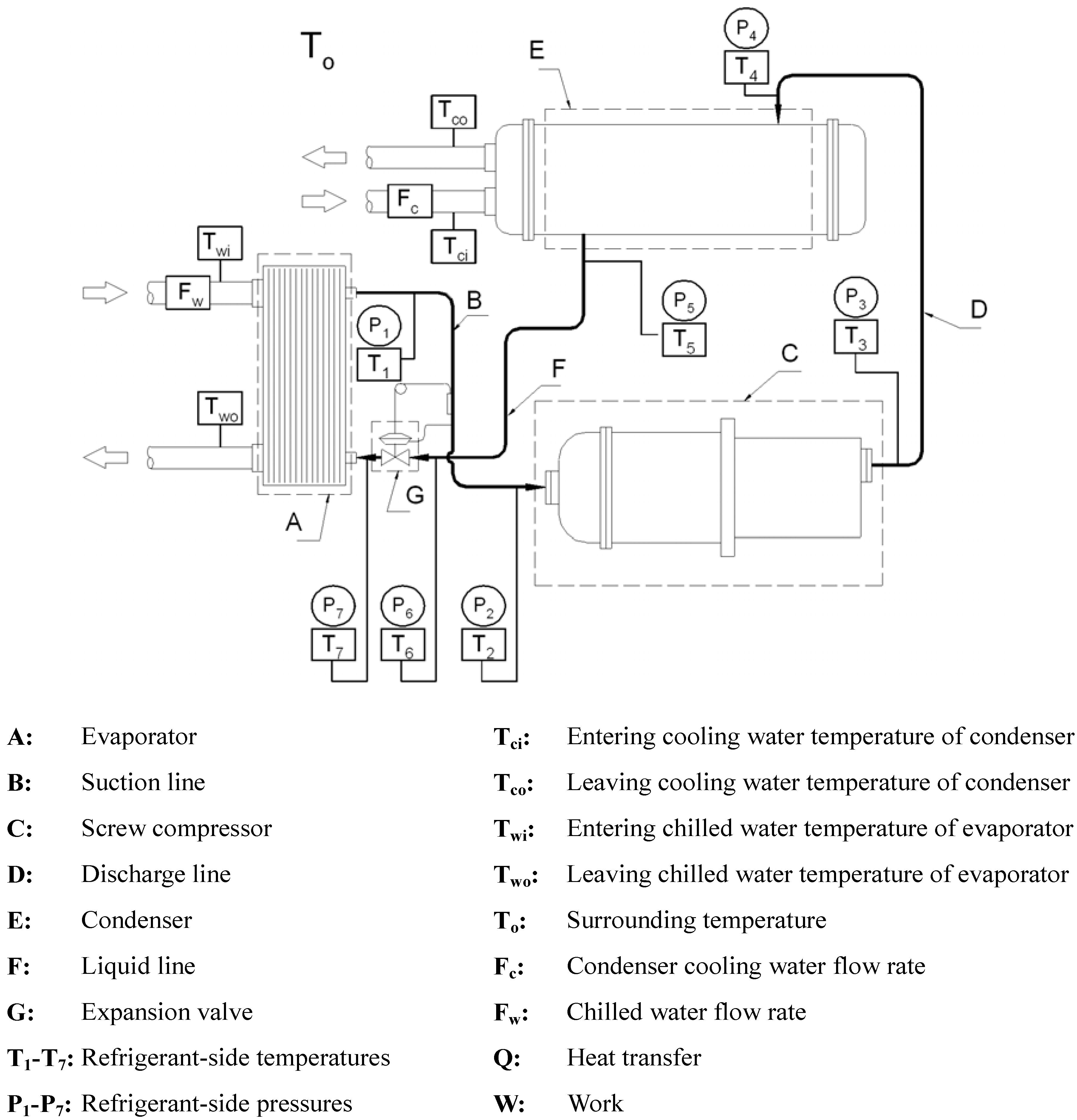
Three sets of chiller units, abbreviated as Units A, B and C, were built and tested under the same conditions to validate the effectiveness of the second-law analysis. Unit A is a typically designed R-22 water-cooled screw liquid chiller with a nominal capacity of 100 RT. Figure 2 schematically depicts the system layout. The compressor is a semi-hermetic twin-screw compressor with a displacement of 380 m3/h. The evaporator is a direct-expansion plate-type heat exchanger. The water-cooled condenser is of the shell-and tube type and made of copper tubes whose exterior surfaces are finned and whose interior surfaces are smooth. The throttling device was a thermostatic expansion valve with an external equalizer.
Figure 2.
The measured points of screw liquid chiller.

Unit B was the same as Unit A, except in that its condenser had been modified by replacing the externally finned and internally smooth copper tubes with externally finned and internally spiral copper tubes, to enhance the heat transfer on the water-side. Finally, Unit C was the same as Unit B, except in that Unit B’s compressor was replaced by a more efficient one with the same displacement. The subcooling temperature of the condenser and the superheating temperature of the evaporator were set to 5 K for all chiller units.
The system used to conduct the chiller tests can supply both chilled- and cooling-water at a flow rate steady to within ± 1%, and at a temperature maintained within ± 0.1%. Four physical parameters were measured-temperature, flow rate, pressure and power input to the compressor. All the measurement instruments conformed to the requirements of ARI 550/590 [15]. Figure 2 presents the position of the mounting of each measuring instrument, while Table 1 states the accuracy of the respective instruments.

| Physical parameter | Instrument | Accuracy | ||
|---|---|---|---|---|
| Temperature | Platinum resistance thermometer | ± 0.03 °C | ||
| Pressure | Pressure transducer | ± 0.15% | ||
| Flow rate | Electromagnetic flow meter | ± 0.5% | ||
| Power consumption | Wattmeter | ± 0.5% |
3.2. Experimental Methods
The testing conditions included setting the temperature of the chilled water that entered and left the unit to 12 ± 0.5°C and 7 ± 0.5°C, and setting the temperature of the cooling water that entered and left the unit to 30 ± 0.5°C and 35 ± 0.5°C. Once the liquid chiller unit reached a steady state and had been kept running for over one hour, physical measurements were taken at 20 minute intervals, four times. The averages of these four sets of data were used in the second-law analysis to quantify irreversibility. In each test, the heat balance was within 5% per ARI Standard 550/590 [15]. Each test was carefully performed at the same temperature of the surroundings in the laboratory, 25°C, to increase the reliability of the test results.
4. Results and Discussion
Table 2 presents the measured temperature and pressure data at each state point in the three chiller units under the same testing conditions, from which the enthalpy, entropy and other thermodynamic properties at each state could be determined. Figure 3 plots a pressure-enthalpy diagram of the vapor compression refrigeration cycle of each chiller unit. The second-law or irreversibility analysis was conducted using the data in Table 2 and the related equations introduced in the theoretical section. Table 3 presents the results of the second-law analysis. Figure 4 compares the exergy destruction of each component for the three chiller units studied in the work. Figure 5 plots the exergy destruction ratio of components for three units. The following discussion of the analytical results is based on Table 3 and Figure 3, Figure 4 and Figure 5.
4.1. Performance of the Baseline Chiller (Unit A)
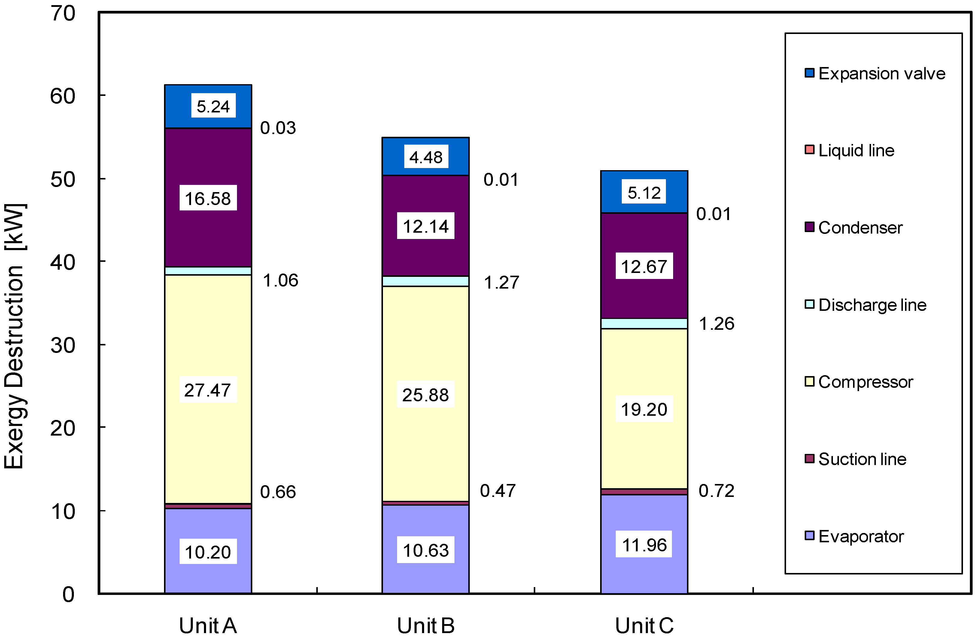
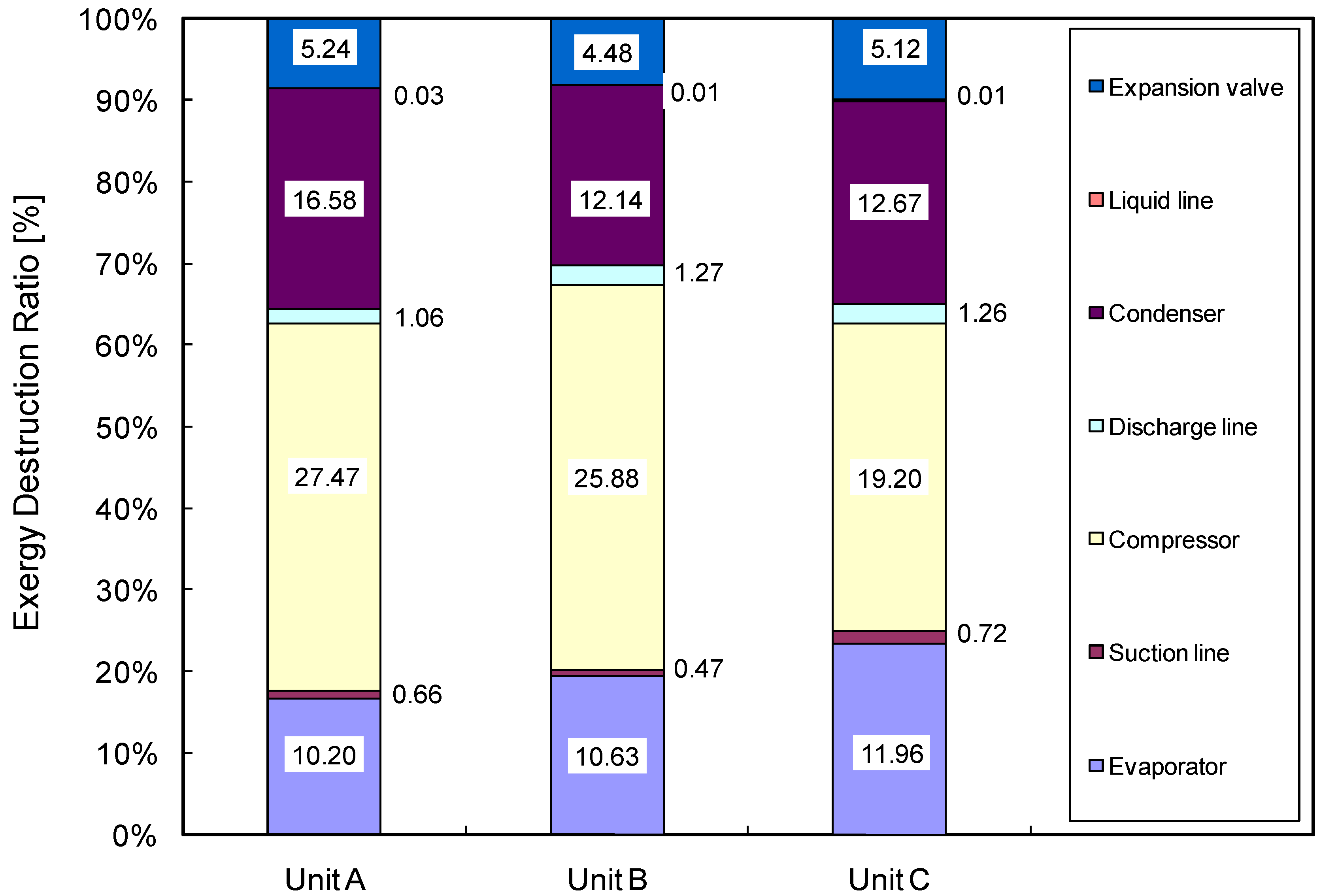
As shown in Table 3, the first-law analysis for Unit A reveals a COP of 3.7. Additionally, the compressor holds the greatest entropy generation, followed in order by the condenser and the evaporator, with the entropy generation of 0.0891, 0.0538 and 0.0331 kW/K, respectively. Figure 4 shows the comparison of exergy destruction associated with components for Units A, B, and C. In the case of Unit A, the compressor exhibited the largest exergy destruction with 27.47 kW, followed by the condenser with 16.58 kW and the evaporator with 10.20 kW. Figure 5 depicts that the exergy destruction ratios were 45%, 27% and 17% for the compressor, the condenser and the evaporator, respectively. The sum of the exergy destruction ratios of these three components approaches 90%. Apparently, these three components should be considered first in increasing the energy efficiency of the screw liquid chiller. The second-law efficiency of Unit A is around 30.27%.
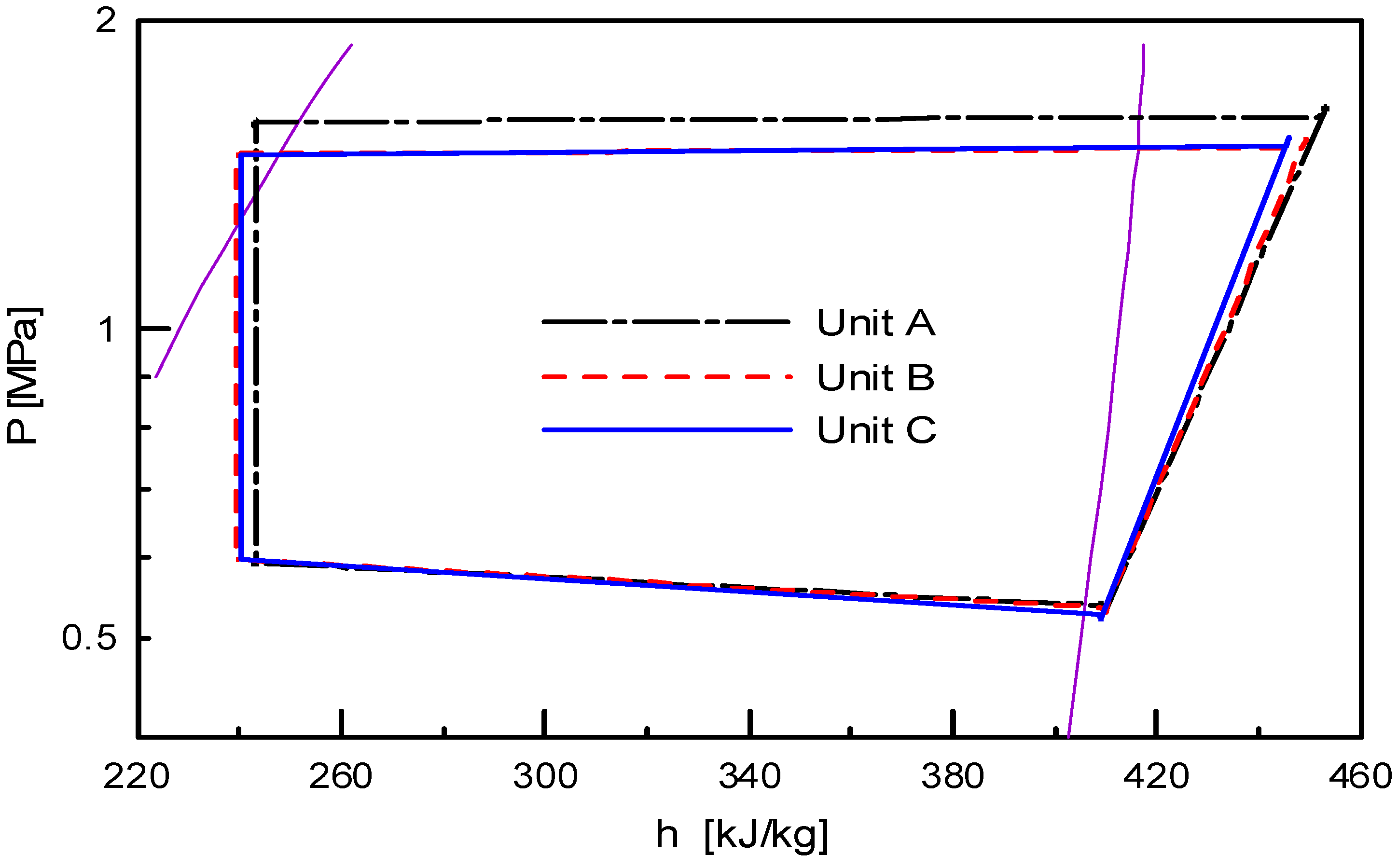
Figure 3.
Pressure-enthalpy diagram of chiller units under the same testing conditions.

Figure 4.
Comparison of exergy destruction associated with components for Units A, B and C.

Figure 5.
Comparison of exergy destruction ratio associated with components for Units A, B and C.

 |
 |
4.2. Effect of Improving Condenser Heat Transfer on Cop (Unit B)
The analytical results in Table 3 show that the COP of the refrigeration cycle is 4.1, which is approximately 10.8% higher than that of Unit A. The entropy generation for each component follows the order of compressor, condenser and evaporator, with values of 0.084, 0.0394 and 0.0345 kW/K, respectively, following the same order as for Unit A. Examining Figure 4 and Figure 5, we find that the highest exergy destruction is that of the compressor at 25.88 kW, followed by that of the condenser at 12.24 kW and then that of the evaporator at 10.63 kW. The exergy destruction ratios for individual component are 47%, 22% and 19%, respectively. Moreover, the sum of the exergy destruction of these three components approaches 88% of the whole unit. The second-law efficiency of Unit B is 33.2%, representing an improvement of around 9.7% over Unit A.
Closely examining Figure 3 and Table 3 yield further important results. Figure 3 compares the refrigeration cycles of the three chiller units and indicates that Unit B exhibited a lower condensing temperature and discharge temperature than that of Unit A. Since Unit B has the same construction as Unit A, except in that its condenser had been modified by replacing the externally finned and internally smooth cooper tubes with externally finned and internally spiral cooper tubes, to enhance the heat transfer on the internal water-side. When the condenser in Unit A was replaced with a new condenser, the heat transfer effect on the water side was increased by the structure of the externally finned and internally spiraling copper tube, reducing the difference between the condensing temperature and that of cooling water, and thus reducing the power consumption of the compressor. Therefore, the entropy generation and the exergy destruction associated with the condenser were reduced, reducing the total exergy destruction and improving the energy efficiency of the Unit. Synthetically analyzing and comparing data concerning each item indicates that replacing the condenser practically promotes heat transfer and increases the energy efficiency of the unit.
4.3. Effect of Improving Compressor Efficiency on Cop (Unit C)
The analytical results for Unit C shown in Table 3 indicate that the COP of the refrigeration cycle is 4.5, which are about 9.8% higher than of Unit B and 20.4% higher than that of Unit A. The amount of entropy generation of each component follows the same order as that for Units A and Unit B- the compressor, followed by the condenser, then by the evaporator, with respective values of 0.0623, 0.0411 and 0.0388. As displayed in Figure 4 and Figure 5, the values of exergy destruction associated with each component in this regard follow the same order as that for Units A and B. The component with the highest exergy destruction remains the compressor at 19.2 kW, followed by the condenser at 12.67 kW and the evaporator at 11.96 kW, yielding exergy destruction ratio of 38%, 25% and 23%, respectively. The summation of these three values is 86% of the total irreversibility, which is lower than that for Unit B. However, the second-law efficiency is further increased to 36.5%, representing improvements of around 20.5% and 10% over that of Unit A and that of Unit B, respectively.
As comparing the refrigeration cycles of the chiller units indicates that the discharge temperature of Unit C was lower than that of Unit B, and the compression process for Unit C was near to isentropic process. Since Unit C was constructed by replacing the compressor in Unit B with a more efficient one, so the compression process of Unit C is more nearly to become isentropic than that of the other two Units, significantly reducing the generation of entropy and the irreversibility of the compressor, thus reducing the total irreversibility. The energy efficiency of the unit is thus increased. All these data reveals that replacing a compressor with one of higher compression efficiency is feasible, and it is particularly helpful in raising the energy efficiency of the liquid chiller.
Second-law analysis explicates the exergy destruction associated with each component in a liquid chiller. It clearly indicates which component is most able to increase the energy efficiency. The analytical method presented herein can be applied not only to evaluate the effectiveness of modifications of components, but also to determine how the efficiency of a component influences the potential payoff of improving another component. Hence, this work has practical value and the method developed in this study can be used as an R&D tool for improving the energy efficiency of screw liquid chillers.
5. Conclusions
This work established a method for identifying the potential of each component in a screw liquid chiller to improve the energy efficiency of chiller by applying second-law analysis. Three liquid chillers were constructed for testing and analysis. The improvements of efficiency and the appropriateness of second-law analysis were clarified in a case study. The results support the following conclusions.
- ♦
- The exergy destruction or irreversibility associated with each component in a screw liquid chiller taken from the testing unit follow the sequence, compressor associated with 38% to 47% of the total system irreversibility, followed by the condenser associated with 22% to 27% thereof, followed by the evaporator associated with 17% to 23%.
- ♦
- A component associated with a higher proportion of exergy destruction may more dramatically contribute to improve energy efficiency of a screw liquid chiller. Reducing the exergy destruction associated with components may increase the system COP and the second-law efficiency.Second-law analysis may help us to identify components with higher exergy destruction, modifications to which have greater potential to increase efficiency.
- ♦
- Second-law analysis is demonstrated to be a feasible and effective means in improving the energy efficiency of a screw liquid chiller.
Nomenclature
specific heat (kJ/kg K) | |
coefficient of performance | |
gravitational acceleration (m/s2) | |
enthalpy (kJ/kg) | |
exergy destruction or irreversibility (kW) | |
mass flow rate (kg/s) | |
heat transfer rate (kW) | |
| RT | refrigerating tons |
specific entropy (kJ/kg K) | |
entropy generation (kJ/K) | |
temperature | |
velocity | |
work | |
elevation |
Greek symbols
second-law efficiency |
Subscripts
| 1,2…,7 | components |
| act | actual |
cooling water inlet and outlet, respectively | |
compressor | |
condenser | |
discharge | |
| exp | expansion valve |
evaporator | |
refrigerant | |
high | |
independent variable (i=1,2,…,n) | |
inlet | |
low | |
liquid | |
surrounding | |
out | |
reversible | |
suction | |
chiller water inlet and outlet, respectively |
Acknowledgements
The authors would like to thank the National Science Council of Taiwan for financially supporting this research under Contract No. NSC92-2622-E-027-020-CC3.
References
- Liang, H; Kuehn, T.H. Irreversibility analysis of a water to water mechanical compression heat pump. Energy 1991, 16, 883–895. [Google Scholar]
- McGovern, J.A.; Harte, S. An exergy method for compressor performance analysis. Int. J. Ref. 1995, 181, 421–433. [Google Scholar] [CrossRef]
- Zubair, S.M.; Yaqub, M.; Khan, S.H. Second-law-based thermodynamic analysis of two-stage and mechanical-subcooling refrigeration cycles. Int. J. Ref. 1996, 19, 506–516. [Google Scholar] [CrossRef]
- Domanski, R.; Fellah, G. Thermoeconomic analysis of sensible heat, thermal energy storage systems. Appl. Therm. Eng. 1998, 18, 693–704. [Google Scholar] [CrossRef]
- Moran, M.J. On second-law analysis and the failed promise of finite-time thermodynamics. Energy 1998, 23, 517–519. [Google Scholar] [CrossRef]
- Lee, S.F.; Sherif, S.A. Second law analysis of a lithium bromide/water absorption system for cooling and heating applications. In Presented at the 20th International Congress of Refrigeration, Sydney, Australia, 19th–24th September, 1999.
- Meunier, F. Second-law analysis of refrigeration cyclic open systems. ASHRAE Trans. 1999, 105, 1. [Google Scholar]
- ASHRAE. 2001 Fundamentals Handbook; ASHRAE: Atlanta, GA, USA, 2001. [Google Scholar]
- Bridges, B.D.; Harshbarger, D.S.; Bullard, C.W. Second law analysis of refrigeration and air conditioners. ASHRAE Transactions 2001, 107, 1. [Google Scholar]
- Bilgen, E; Takahashi, H. Exergy analysis and experimental study of heat pump systems. Exergy 2002, 2, 259–265. [Google Scholar]
- Yumrutaş, R; Kunduz, M; Kanoğlu, M. Exergy analysis of vapor compression refrigeration systems. Exergy 2002, 2, 266–272. [Google Scholar]
- Ozgener, O.; Hepbasli, A. Experimental performance analysis of a solar assisted ground-source heat pump greenhouse heating system. Energ. Bldg. 2005, 37, 101–110. [Google Scholar]
- Esen, H.; Inalli, M.; Esen, M.; Pihtili, K. Energy and exergy analysis of a ground-coupled heat pump system with two horizontal ground heat exchangers. Bldg. Environ. 2007, 42, 3606–3615. [Google Scholar] [CrossRef]
- Bejan, A. Advanced Engineering Thermodynamics; John Wiley & Sons: New York, NY, USA, 1998. [Google Scholar]
- ARI. Water Chilling Packages Using the Vapor Compression Cycle; ARI: Arlington, VA, USA, 1998. [Google Scholar]
© 2010 by the authors; licensee Molecular Diversity Preservation International, Basel, Switzerland. This article is an open-access article distributed under the terms and conditions of the Creative Commons Attribution license (http://creativecommons.org/licenses/by/3.0/).
Share and Cite
MDPI and ACS Style
Lee, T.-S. Second-Law Analysis to Improve the Energy Efficiency of Screw Liquid Chillers. Entropy 2010, 12, 375-389. https://doi.org/10.3390/e12030375
AMA Style
Lee T-S. Second-Law Analysis to Improve the Energy Efficiency of Screw Liquid Chillers. Entropy. 2010; 12(3):375-389. https://doi.org/10.3390/e12030375
Chicago/Turabian StyleLee, Tzong-Shing. 2010. "Second-Law Analysis to Improve the Energy Efficiency of Screw Liquid Chillers" Entropy 12, no. 3: 375-389. https://doi.org/10.3390/e12030375