How to Automate a Kinematic Mount Using a 3D Printed Arduino-Based System


1
Aistech Space, Esteve Terrades 1, Despacho 110, 08860 Castelldefels, Barcelona, Spain
2
ICFO-Institut de Ciencies Fotoniques, the Barcelona Institute of Science and Technology, Mediterranean Technology Park, 08860 Castelldefels, Barcelona, Spain
3
Department of Signal Theory and Communications, Universitat Politecnica de Catalunya, BarcelonaTech, 08034 Barcelona, Spain
*
Author to whom correspondence should be addressed.
Inventions 2018, 3(2), 39; https://doi.org/10.3390/inventions3020039
Submission received: 15 March 2018
/
Revised: 5 June 2018
/
Accepted: 13 June 2018
/
Published: 19 June 2018
(This article belongs to the Special Issue Innovations in 3-D Printing)
Abstract
:We demonstrate a simple, flexible and cost-effective system to automatize most of the kinematic mounts available nowadays on the market. It combines 3D-printed components, an Arduino board, stepper motors and simple electronics. The developed system can control up to ten stepper motors independently and simultaneously using commands sent through the serial port, and it is suitable for applications where optical realignment using flat mirrors is required on a periodic basis.
1. Introduction
Over the last few years, the combination of 3D printing and Arduino has proven to be an efficient and cost-effective way of making experimental equipment [1], becoming on many occasions an attractive alternative to its commercial counterparts.
In fact, the implementation of opto-mechanical components using 3D printing technology is having a direct impact on the scientific community [2,3], firstly, because researchers are no longer constrained to work with commercially available products, and therefore, their experimental setups can be made more versatile. Secondly, since the materials, fabrication techniques and electronic components are evolving very fast, and the characteristics and quality of the equipment developed can improve significantly from the experience and needs of the researcher [4,5]. Lastly, the development process turns out to be a creative way to engage young researchers in science and increase the size of the scientific open-source hardware and software community thanks to the fact that several open-source platforms are currently available and the detailed building instructions are shared [6,7,8,9].
Interestingly the term open-source laboratory equipment spans a large variety of applications ranging from a simple laboratory clamp [10] that requires only 3D printing and simple hardware, to more advanced instruments such as a system to determine the concentration of dissolved species [11], a system to provide a carefully controlled dose of a given reagent [12,13], a device to characterize the spatial profile of a laser beam easily [14], a centrifuge for DNA extraction [15] or a 3D-printable open-source platform for fluorescence microscopy [16], to name a few.
In this paper, we report the development of a system that can motorize many of the kinematic mounts available nowadays on the market. It combines 3D-printed components, simple hardware and electronics and an Arduino board. The system is intended to add automation capabilities to the Open-Source Optics Library [2] already available on the Internet. The library is composed of a broad selection of optical components ubiquitous in any optics experiment such as lens holders [17], screen/filter holders [18,19], lab jacks [20], fiber optic holders [21], kinematic mirrors and translation stages [22,23] and parametric open-source chopper wheels [24], to name a few.
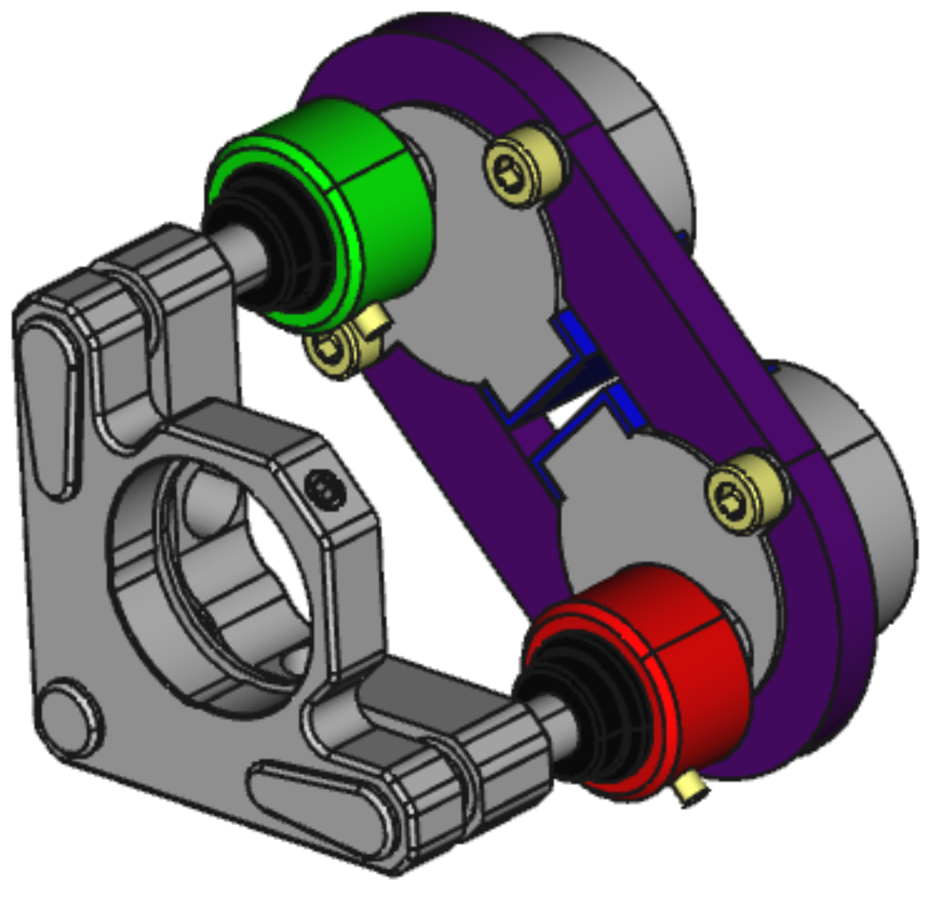
The system we demonstrate here is simple, flexible and cost effective. The simplicity of the system relies on the components used to implement it. It is composed of a 3D-printed plate that supports two stepper motors 28BYJ-48 [25]. Its shafts are aligned with the knobs used to tip and tilt the plane of the kinematic mount that supports the optics (see Figure 1). The cylindrical adapter used to couple the shaft to the knob is also 3D printed. An Arduino MEGA controls the motors. In order to simplify the connections with the motor drivers, a shield (Sensor Shield V1.0) [25] provides the capability of controlling up to ten motors simultaneously by sending simple instructions defined by a command table through the serial port.
The hardware and software of the system are flexible and can be easily modified according to the user needs. From the hardware side, since the 3D-printed components that couple the system to the kinematic mount were parametrically designed using FreeCAD 0.16 [26], the system is highly tunable by changing only a few parameters in a spreadsheet. Similarly, from the software side, the Arduino code is well documented, and some usage examples are provided in the *.ino file. The FreeCAD and Arduino source code can be downloaded from the repositories Thingiverse [27] and Github [28], respectively.
The low cost of the system is the byproduct of its simplicity. As a reference, the average cost of fabricating a system composed of four stepper motors for controlling two kinematic mounts is around 30€. The system presented in this letter thus compares favorably with respect to commercial alternatives, since it can be roughly between five- and 10-times less expensive. However, a word of caution should be added here. Since the system keeps track of the number of steps given by the stepper motor of each channel to estimate its current position, some inaccuracies may appear due to the hysteresis present on the stepper motors. Therefore, the true usefulness of the system presented in this work will depend on its specific aim. Based on our experience in the laboratory in a research institute, we find that the system is suitable for a wealth of applications ranging from teaching to doing high-quality research experiments.
To illustrate and validate the system developed, we consider two scenarios that may require the use of two mirrors supported by two kinematic mounts. The first scenario is the alignment of a laser beam through two reference apertures, and the second scenario is the coupling of light into a multimode or single-mode optical fiber. Both scenarios might be of great interest to experimenters that require re-aligning an optical beam or increasing the coupling efficiency of an optical fiber on a daily basis.
2. Materials and Methods
We have designed and implemented a system that can provide full automatic control of a vast majority of standard kinematic mounts available on the market. It combines open-source resources such as 3D printing and simple electronics.
A single unit of the system, capable of controlling the tip and tilt of a kinematic mount, is composed of two stepper motors attached to a 3D-printed plaque that aligns the knobs of the kinematic mount with the axis of the motors. The axis is coupled to the knobs using a 3D-printed knob adapter. The motor drivers are connected to an Arduino MEGA sensor shield (attached to an Arduino MEGA) using Dupont wire jumper cables. Table 1 provides the list of materials required to motorize a kinematic mount for a single channel, as well as their estimated cost.
2.1. Hardware
Figure 2a provides a connection diagram for a single unit that makes use of two channels (tip and tilt). Each channel is composed of a stepper motor 28BYJ-48, driver electronics and a Dupont cable patch with six wires. Given the number of output pins available on the Arduino sensor shield, the board can be used to control up to five kinematic mounts simultaneously, as shown in Figure 2b.
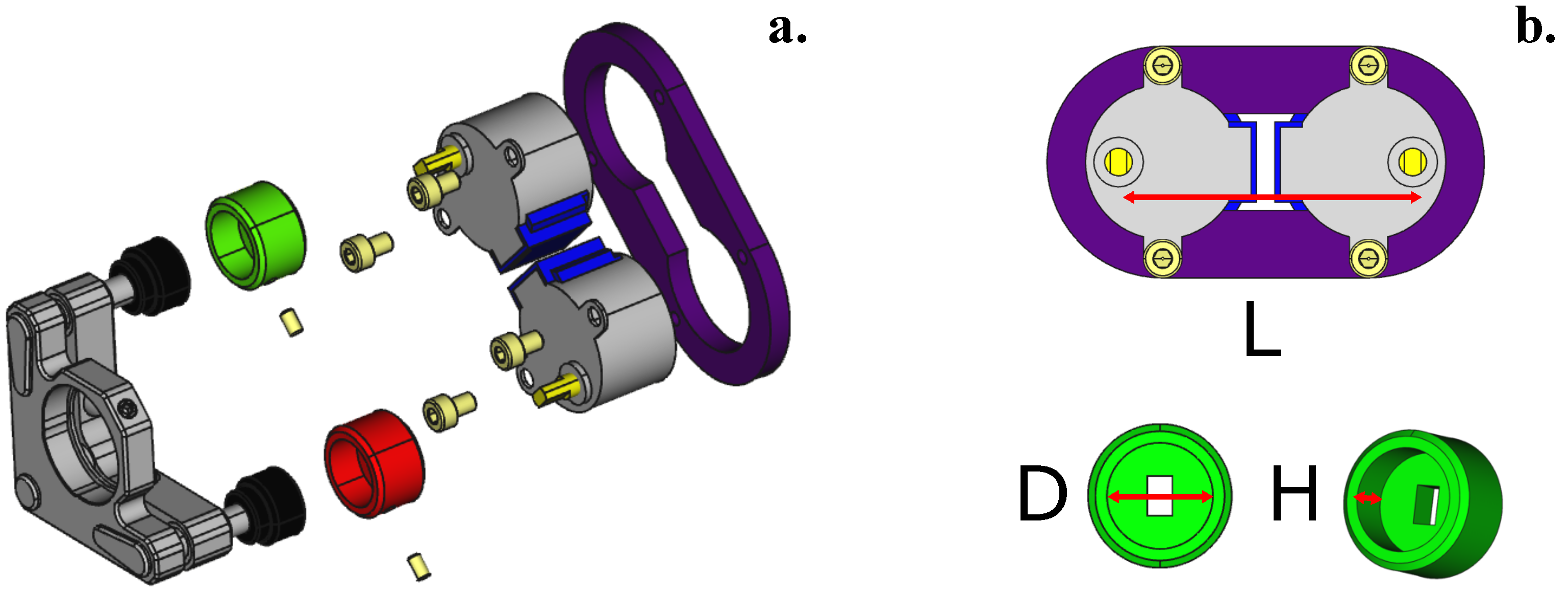
Since the 3D-printed components that couple the stepper motors to the kinematic mount were designed using FreeCAD 0.16, the distance between the motor axis on the plate and the inner diameter and height on the knob adapters can be easily modified using a spreadsheet. To attach the motors to the plastic plate, four M4 screws are required, whereas two M3 grub screws are used to secure the knobs to the knob adapters (see Figure 3).
Table 2 provides information on the parameters used for customizing the plate and the knob adapter to fit into four different types of kinematic mounts (see Figure 3b). The FreeCAD FCStdfiles are available on Thingiverse [27].
Regarding the motors used, the 28BYJ-48 is a very inexpensive stepper motor that requires five wires for its connection to the motor driver circuit. The motor can operate in the voltage range from 5 V–12 V and gives 4096 steps per one turn. This number comes from the fact that the internal stepper motor that requires 64 steps to give a complete turn is connected to a set of gears that provide a reduction ratio of 1/64. As a result, the 28BYJ-48 requires steps to complete a full turn.
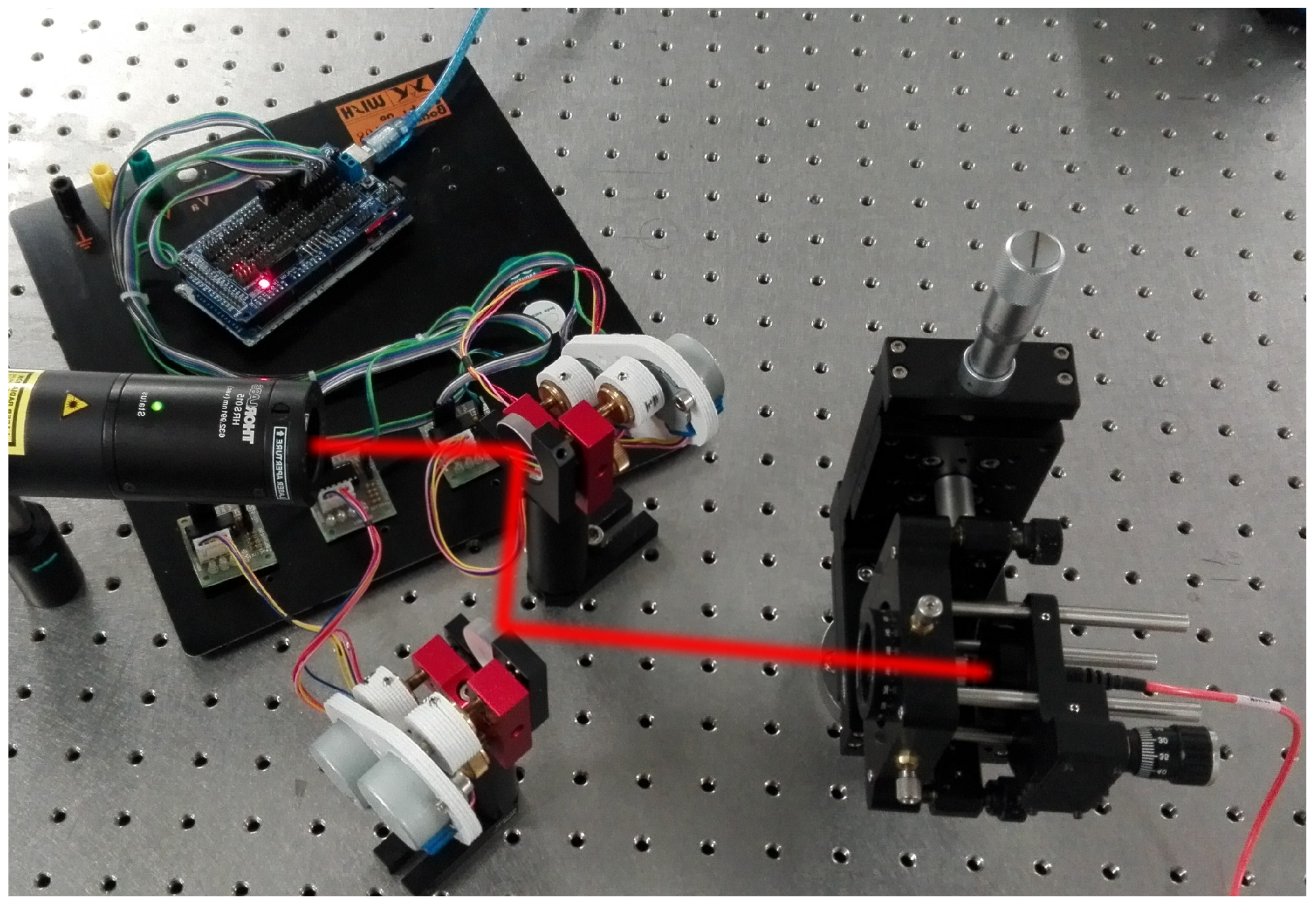
For the sake of illustration, Figure 4 shows the experimental setup corresponding to Figure 5b, where two kinematic mounts from Radiant Dyes are motorized. Notice that for each channel, we have used the following components: one 3D-printed supporting plate, two 3D-printed knob couplers, two stepper motors and the corresponding driving electronics. In this particular case, the power supplied by the USB port is enough to move the motors. However, in order to control more than four stepper motors simultaneously, it may be necessary to connect the sensor shield to an external power supply.
2.2. Software
In order to provide flexibility and simplicity from the software perspective, each motor is controlled independently by sending a simple instruction defined by a command table through the serial port. A command table is a dictionary of instructions that can be divided into two categories: commands and queries. The first category corresponds to a direct order such as “move stepper motor connected to port 3, half-turn”. The second type of command is used to ask information of the device about its status; for example, the state of a digital variable, the value of a given counter or the identification string that contains relevant information about the device and its manufacturer.
For reference, Table 3 shows the complete list of commands used to control and retrieve information about the status of each motor connected to the Arduino board. Since the status of each motor is determined by a variable that keeps track of the number of steps given by the motor, there is assumed to be a one-to-one correspondence between the number of steps defined by software and the number of steps given by the axis of the motor. A step in the clock-wise direction adds one unit to the global counter; a step in the counter-clock-wise direction subtracts a unit. To keep the current status of each motor over time, the value of each global counter is stored in the non-volatile section of the Arduino (EEPROM memory) so that all the information is available even though the Arduino board is powered off.
Since the control method is based on a command table, there are many alternatives to implement the software interface that controls the system. Depending on the application, the user may require performing simple actions driven by simple commands, or a more elaborate sequence of tasks dependent on external signals, or defined by an algorithm with temporal dependence. The former can be implemented by sending commands through the serial port using a serial communication terminal compatible with the RS232 standard such as Termite [29], and the latter can be implemented using MATLAB, Python or other software.
In our implementation, a MATLAB routine communicates with the Arduino board, moves the stepper motors and reads the power detected by a Thorlabs PM100-A detector. The beam auto-alignment procedure is carried out by scanning the X-Y plane in two steps: firstly, the horizontal direction (X) is scanned a certain number of steps while the optical power is measured. Afterwards, the vertical direction (Y) is scanned. In each step, the power and motor position are recorded and stored in a *.dat file. When the loop finishes, the algorithm returns the motors to the position at which maximum power was detected. The power is first maximized for the X direction and later for the Y direction.
The number of steps used in each scan is selected initially by the user. Larger ranges lead to a wider scanning of the X-Y plane. This setting is advisable for a first approximation, while smaller rotational ranges guarantee the convergence and optimization of the auto-alignment method implemented in MATLAB.
3. Results
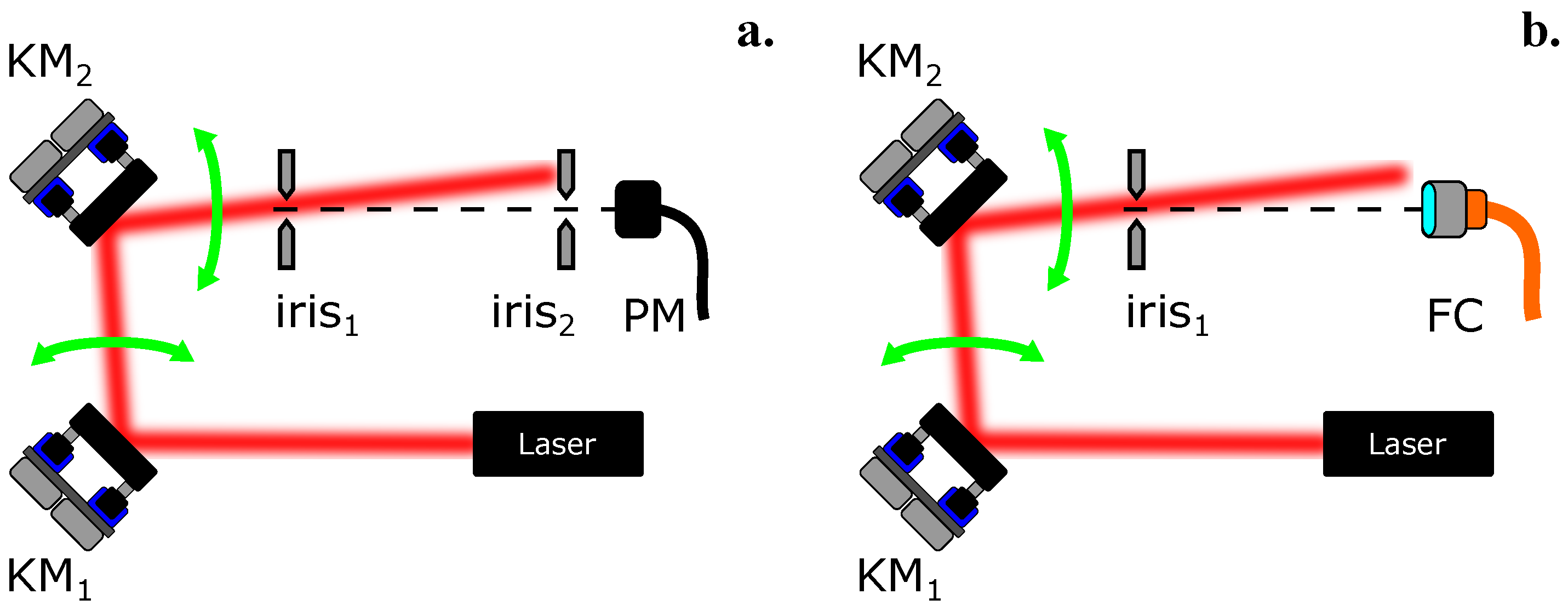
To validate and test the performance of the motorized system, we implemented the two experimental schemes shown in Figure 5. We used a HeNe laser and aligned the laser beam with the help of two mirrors supported by two kinematic mounts, and .
In each experiment, the tip and tilt of each of the two mirrors were automatically controlled using a MATLAB routine. The power after the second iris (Figure 5a) or at the output of the fiber (Figure 5b) was monitored using a Thorlabs PM100A power meter. After scanning sequentially the tip and subsequently the tilt of both mirrors, the final position of each kinematic mount was set to the position that corresponds to the maximum power registered.
3.1. Alignment of an Optical Beam with the Help of Two Irises
The experimental scheme is shown in Figure 5a. The initial position of the mirrors (without using the stepper motors) was set so that the optical beam hits the first iris close to its center. This coarse alignment was mainly driven by the first mirror . Once the starting point was defined, the motors were attached to the kinematic mounts knobs, and a simple MATLAB routine was executed where each motor moved independently a defined number of steps either in a clock-wise or anti-clockwise direction. The optical power was measured by the detector located after the second iris.
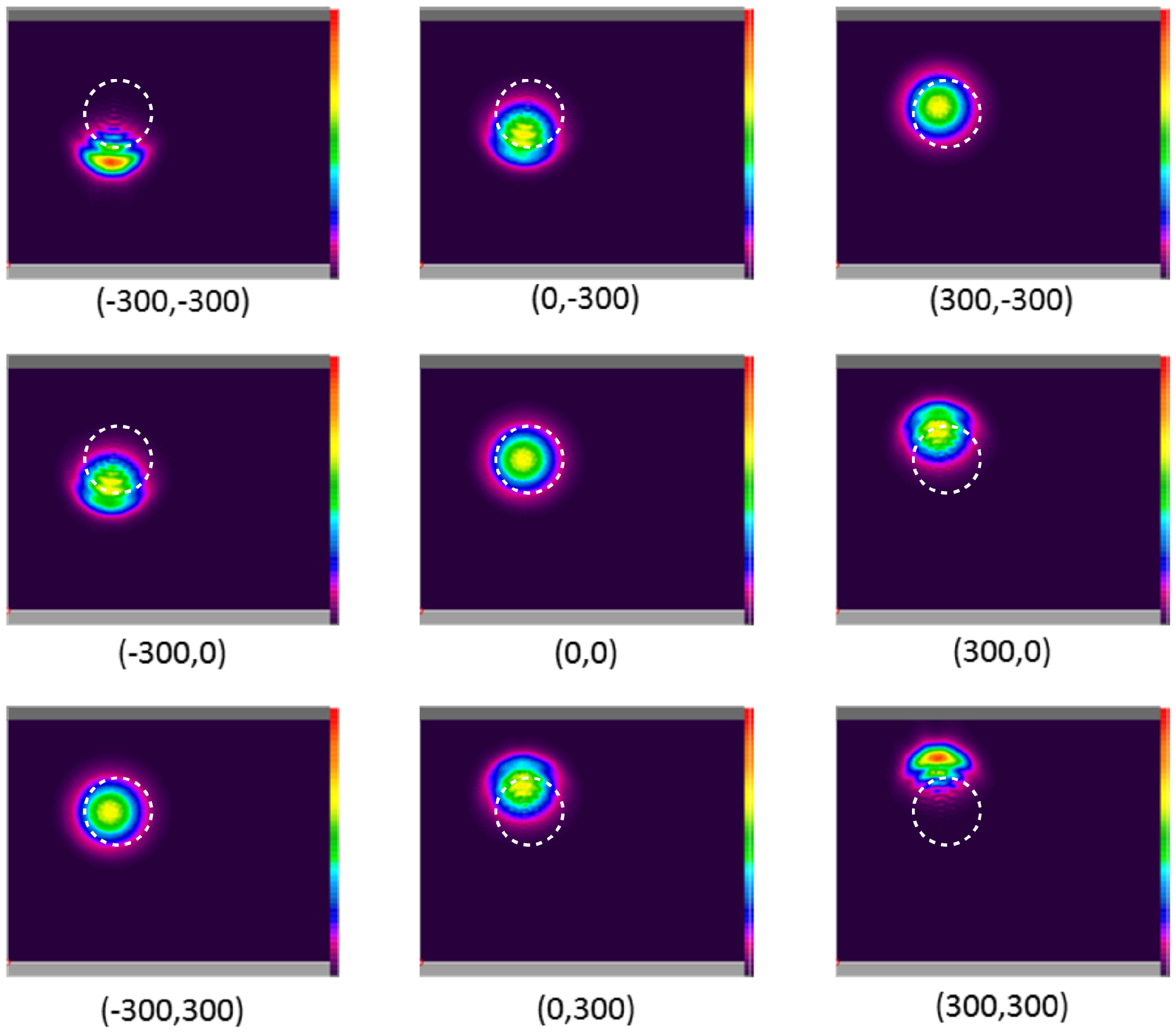
To illustrate a step-by-step run of the MATLAB routine, a CCD camera was placed just after the second iris, and a beam image was acquired for several positions of both motors. Figure 6 and Figure 7 show the beam position registered for a given combination of steps in the X and Y directions, respectively. As a reference, the position of the second iris (set at a given aperture) is indicated by a dashed circle in all images.
In the example, each motor and was set to move between three different positions separated by 300 steps, so that each motor could move between the absolute positions , 0 and 300. As a result, a full scan in the X and Y directions was defined by nine different positions indicated by the array below each figure.
Notice that the maximum power was registered for the positions , while the positions with opposite angles and corresponded to a situation where the effect of one mirror was compensated by the other and the centroid of each beam was slightly shifted to the right or left, respectively.
3.2. Optimizing the Coupling Efficiency of a Light Beam in an Optical Fiber
We replaced the second iris of the previous experimental setup by a multi-mode optical fiber (see Figure 5b). The aim was to test the performance of the system and the simple routine written in MATLAB code for optimizing the coupling of light into an optical fiber. The motors attached to the 3D-printed kinematic mounts performed a scan in the X direction and later in the Y direction, controlled by a MATLAB program.
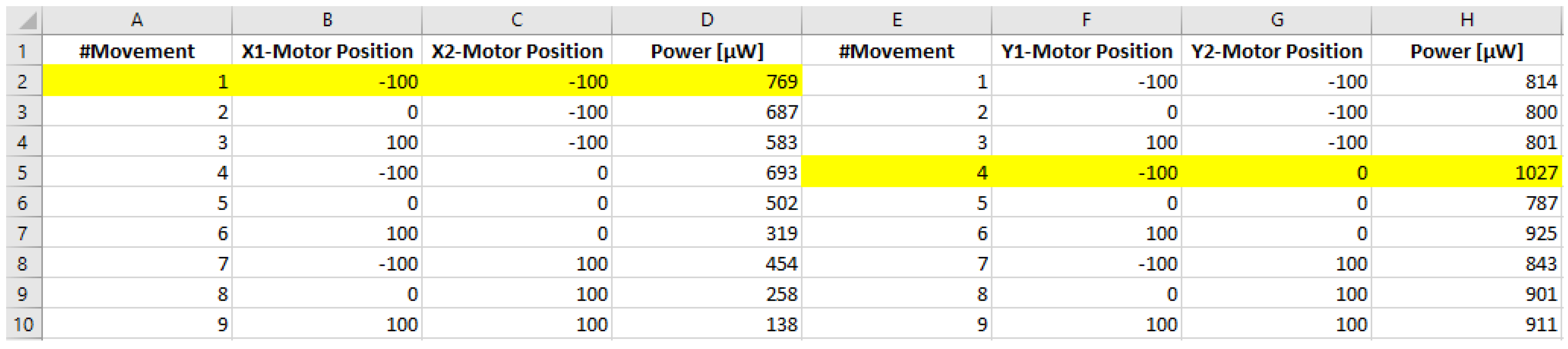
Figure 8 shows a table with the data obtained after performing a full scan in both directions. First, the X scan provided a power maximum (highlighted), which was used as the starting point for a second scan in the Y direction (highlighted).
After the scan in the X and Y directions, the motors would move to positions and , respectively. For this final situation, the recorded power was 1027 W. Taking into account that the input power of the laser was 1250 W, we obtained that the laser-fiber coupling efficiency was .
4. Discussion
The combination of 3D printing, simple hardware and Arduino-based electronics has proven to be a very effective alternative to substitute expensive and sometimes over-engineered systems with equipment that, despite costing a fraction of its commercial counterpart, can be used to perform state-of-the-art research [1,23].
This is precisely the case of aligning a beam through two irises and coupling light in an optical fiber. In principle, both tasks are typically carried out manually in an optics laboratory. However, it is desirable that both tasks can be carried out automatically in order to optimize research time.
Table 4 shows a selection of motorized kinematic mounts available on the market. From the table, it is clear that for some institutions or laboratories, the use of automatic equipment is simply cost-prohibitive if it is intended to be used only to perform beam alignment.
Given the simplicity of the components used, the system may experience some hysteresis that may not be suitable for applications requiring high accuracy or precision. However, we have demonstrated that the system proposed can be used in two very specific scenarios since it does not compromise the quality of the experimental data obtained. As a result, the experimenter must evaluate on an experimental basis to what extent inaccuracies inherent to the quality of the components used in the experimental setup can be withstood.
5. Conclusions
In this article, we demonstrate a system that can be used to motorize most of the kinematic mounts available on the market. Notwithstanding it being implemented using 3D-printed components, an Arduino board and simple electronics, the system has proven to be effective, simple, flexible and low cost. After performing two different experiments where a laser beam is aligned through two reference points, we can conclude that the system is suitable for applications where optical realignment using flat mirrors mounted on kinematic mounts is required on a periodic basis. Even though the system was initially intended to motorize kinematic mounts, its hardware and software can be easily extended to control other opto-mechanical components, such as translation stages.
Author Contributions
L.J.S.-S. and G.J. conceived of and designed the experiments. L.J.S.-S implemented the motorized kinematic mount system. G.J. performed the experiments. L.J.S.-S., G.J. and J.P.T. analyzed the data. L.J.S.-S., G.J. and J.P.T. wrote the paper.
Conflicts of Interest
The authors declare no conflict of interest.
Abbreviations
The following abbreviations are used in this manuscript:
| KM | Kinematic mount |
| PM | Power meter |
| FC | Fiber coupler |
| MM | Multi-mode optical fiber |
References
- Pearce, J.M. Open-Source Lab: How to Build Your Own Hardware and Reduce Research Costs, 1st ed.; Elsevier: New York, NY, USA, 2014; ISBN 9780124104860. [Google Scholar]
- Zhang, C.; Anzalone, N.C.; Faria, R.P.; Pearce, J.M. Open-Source 3D-Printable Optics Equipment. PLoS ONE 2013, 8, e59840. [Google Scholar] [CrossRef] [PubMed]
- Baden, T.; Chagas, A.M.; Gage, G.; Marzullo, T.; Prieto-Godino, L.L.; Euler, T. Open Labware: 3-D Printing Your Own Lab Equipment. PLoS Biol. 2015, 3, e1002086. [Google Scholar] [CrossRef] [PubMed]
- Laureto, J.J.; Pearce, J.M. Open Source Multi-Head 3D Printer for Polymer-Metal Composite Component Manufacturing. Technologies 2017, 5, 36. [Google Scholar] [CrossRef]
- Olsson, A.; Hellsing, M.S.; Rennie, A.R. New possibilities using additive manufacturing with materials that are difficult to process and with complex structures. Phys. Scr. 2017, 92, 053002. [Google Scholar] [CrossRef] [Green Version]
- Open-labware.net. Available online: https://open-labware.net/ (accessed on 25 May 2018).
- Open Tool Kit. Available online: https://channels.plos.org/open-source-toolkit (accessed on 25 May 2018).
- Open-Source Scientific Tools. Available online: https://www.thingiverse.com/jpearce/collections/open-source-scientific-tools (accessed on 25 May 2018).
- Generic Lab Equipment. Available online: https://hackteria.org/wiki/Generic_Lab_Equipment (accessed on 25 May 2018).
- Lab Equipment Clamp. Available online: https://www.thingiverse.com/thing:1132124 (accessed on 10 March 2018).
- Anzalone, G.C.; Glover, A.G.; Pearce, J.M. Open-Source Colorimeter. Sensors 2013, 13, 5338–5346. [Google Scholar] [CrossRef] [PubMed] [Green Version]
- Wijnen, B.; Hunt, E.J.; Anzalone, G.; Pearce, J.M. Open-source Syringe Pump Library. PLoS ONE 2014, 9, e107216. [Google Scholar] [CrossRef] [PubMed]
- Lake, J.R.; Heyde, K.C.; Ruder, W.C. Low-cost feedback-controlled syringe pressure pumps for microfluidics applications. PLoS ONE 2017, 12, e0175089. [Google Scholar] [CrossRef] [PubMed]
- Hossain, M.A.; Canning, J.; Cook, K.; Jamalipour, A. Smartphone laser beam spatial profiler. Opt. Lett. 2015, 40, 5156–5159. [Google Scholar] [CrossRef] [PubMed]
- F.Lab’s DIYbio Centrifuge. Available online: http://www.thingiverse.com/thing:1175393 (accessed on 25 October 2016).
- Chagas, M.A.; Prieto-Godino, L.L.; Arrenberg, A.B.; Baden, T. The €100 lab: A 3D-printable open-source platform for fluorescence microscopy, optogenetics, and accurate temperature control during behaviour of zebrafish, Drosophila, and Caenorhabditis elegans. PLoS Biol. 2017, 15, e2002702. [Google Scholar] [CrossRef] [PubMed]
- Open-Source Lens Holder. Available online: http://www.thingiverse.com/thing:26752 (accessed on 24 October 2016).
- Square Filter Holder for Open-Source Optics. Available online: http://www.thingiverse.com/thing:31483 (accessed on 24 October 2016).
- Screen holder for OpenBeam Optical Rail. Available online: http://www.thingiverse.com/thing:31403 (accessed on 24 October 2016).
- Open-Source Lab Jack. Available online: http://www.thingiverse.com/thing:28298 (accessed on 24 October 2016).
- Open-Source Fiber Optic Holder. Available online: http://www.thingiverse.com/thing:28187 (accessed on 24 October 2016).
- Kinematic Mirror/Lens Mount. Available online: http://www.thingiverse.com/thing:30727 (accessed on 24 October 2016).
- Salazar-Serrano, L.J.; Torres, J.P.; Valencia, A. A 3D Printed Toolbox for Opto-Mechanical Components. PLoS ONE 2017, 12, e0169832. [Google Scholar] [CrossRef] [PubMed]
- Parametric Open-Source Chopper Wheel. Available online: http://www.thingiverse.com/thing:28121 (accessed on 24 October 2016).
- Component Purchased on the Aliexpress Webpage. Available online: https://www.aliexpress.com/ (accessed on 24 October 2016).
- FreeCAD. Available online: http://www.freecadweb.org (accessed on 2 February 2017).
- Motorized Kinematic Mount. Available online: http://www.thingiverse.com/thing:2809159 (accessed on 1 March 2018).
- Motorized Kinematic Mount (MKM). Available online: http://github.com/totesalaz/MKM (accessed on 1 March 2018).
- Termite: A Simple RS232 Terminal. Available online: https://www.compuphase.com/software_termite.htm (accessed on 1 March 2018).
Figure 1.
Design in FreeCAD showing the implementation of the motorized system for a kinematic mount from Thorlabs (KM100). 3D-printed components are shown in green, red and purple.
Figure 1.
Design in FreeCAD showing the implementation of the motorized system for a kinematic mount from Thorlabs (KM100). 3D-printed components are shown in green, red and purple.

Figure 2.
Connection diagram for two channels. (a) shows the connection diagram between the motors and the driver electronics; (b) shows the different ports available on the Arduino sensor shield.
Figure 2.
Connection diagram for two channels. (a) shows the connection diagram between the motors and the driver electronics; (b) shows the different ports available on the Arduino sensor shield.

Figure 3.
Exploded view of the mechanical interface. (a) the motors are attached to the 3D-printed plaque (shown in violet) using four M4 screws. The 3D-printed adapter knobs (shown in green and red) are secured to the kinematic mount knobs using M3 grub screws; (b) dimensions that can be controlled using the parametric FreeCAD file.

Figure 4.
Overall image of the system used to improve the light coupling efficiency into a multi-mode (MM) optical fiber.
Figure 4.
Overall image of the system used to improve the light coupling efficiency into a multi-mode (MM) optical fiber.

Figure 5.
Experimental schemes. (a) alignment of a laser beam through two reference apertures; (b) coupling of light into a multimode or single-mode optical fiber. KM1 and KM2: kinematic mounts; PM: power meter; FC: fiber coupler.
Figure 5.
Experimental schemes. (a) alignment of a laser beam through two reference apertures; (b) coupling of light into a multimode or single-mode optical fiber. KM1 and KM2: kinematic mounts; PM: power meter; FC: fiber coupler.

Figure 6.
X direction scan. Below each capture, in brackets, (X1-motor position, X2-motor position).
Figure 6.
X direction scan. Below each capture, in brackets, (X1-motor position, X2-motor position).

Figure 7.
Y direction scan. Below each capture, in brackets, (Y1-motor position, Y2-motor position).
Figure 7.
Y direction scan. Below each capture, in brackets, (Y1-motor position, Y2-motor position).

Figure 8.
Optimization of light coupling in an optical fiber. Example of the data collected and saved in the .dat file generated by the MATLAB program after performing a scan in the X and Y directions.
Figure 8.
Optimization of light coupling in an optical fiber. Example of the data collected and saved in the .dat file generated by the MATLAB program after performing a scan in the X and Y directions.


Table 1.
List of materials.
| Component | Quantity | Unit Cost (€) |
|---|---|---|
| Parametric plaque (3D printed) | 1 | 2 |
| Knob adapter (3D printed) | 2 | 2 |
| M3 screw | 4 | 0.25 |
| Motor 28BYJ-48 | 2 | 1.5 |
| Arduino MEGA board | 1 | 10.0 |
| Sensor shield for Arduino MEGA | 1 | 3.0 |
| Dupont cable (patch of 6 cables) | 2 | 1 |
| Total | 25 |
Table 2.
Parameters for 3D-printed components. All dimensions are in millimeters.
| Parameter | Variable | PLA | Radiant Dyes | Thorlabs | Liop-Tec |
|---|---|---|---|---|---|
| Plaque axis distance | L | 45.0 | 43.8 | 53.3 | 49.0 |
| Knob diameter | D | 15.0 | 16.1 | 14.5 | 15.0 |
| Knob height | H | 9.0 | 6.0 | 8.0 | 9.0 |
Table 3.
List of commands and queries to control and retrieve information from the stepper motors.
| Command | Description |
|---|---|
| STPM:N:ABS:X | move STePper Motor N to ABSolute position X (in steps) |
| STPM:N:REL:X | move STePper Motor N, RELative to current position |
| STPM:N:RST | ReSeT STePper Motor N counter to 0 |
| STPM:N:VEL:X | set STePper Motor N, VELocity to X, where X [1 fast | 10 slow] |
| STPM:N:ST? | retrieve motor N current STatus (position, velocity, state) |
| velocity -> [1 fast | 10 slow] | |
| state -> [0 stop | 1 moving] | |
| STOP | emergency stop. Press reset button to restart |
Table 4.
Selected commercially available motorized kinematic mounts.
| Company | Software | Hardware | Price (€) |
|---|---|---|---|
| Newport | PicomotorTM | 8806 Picomotor Motorized Blank Plate Mount | 1885 |
| Edmund Optics | Via RS-232 Serial Interface | Motorized Kinematic Mount | 1595 |
| Standa | 8SMC5-USB Stepper and DC Motor Controller | 8MBM24-Motorized Mirror Mounts | 940 + 699 |
| Physik Instrumente (PI) | PI Mikromove | N-480 PiezoMike Linear Actuator | 2109.03 |
| Thorlabs | K-Cube DC Servo Motor Controller (Kinesis® or APT™ Software Packages) | KS1-Z8 DC Motorized Mirror Mount | 580.41 + 1218.97 |
© 2018 by the authors. Licensee MDPI, Basel, Switzerland. This article is an open access article distributed under the terms and conditions of the Creative Commons Attribution (CC BY) license (http://creativecommons.org/licenses/by/4.0/).
Share and Cite
MDPI and ACS Style
Salazar-Serrano, L.J.; Jiménez, G.; Torres, J.P. How to Automate a Kinematic Mount Using a 3D Printed Arduino-Based System. Inventions 2018, 3, 39. https://doi.org/10.3390/inventions3020039
AMA Style
Salazar-Serrano LJ, Jiménez G, Torres JP. How to Automate a Kinematic Mount Using a 3D Printed Arduino-Based System. Inventions. 2018; 3(2):39. https://doi.org/10.3390/inventions3020039
Chicago/Turabian StyleSalazar-Serrano, Luis José, Gerard Jiménez, and Juan P. Torres. 2018. "How to Automate a Kinematic Mount Using a 3D Printed Arduino-Based System" Inventions 3, no. 2: 39. https://doi.org/10.3390/inventions3020039