Article

Effect of Calcium on the Hot Working Behavior of AZ31-1.5 vol.% Nano-Alumina Composite Prepared by Disintegrated Melt Deposition (DMD) Processing

by
Kamineni Pitcheswara Rao
1,*,
Chalasani Dharmendra
1,†,
Kalidass Suresh
1,‡,
Yellapregada Venkata Rama Krishna Prasad
2 and
Manoj Gupta
3
1
Department of Biomedical Engineering, City University of Hong Kong, Tat Chee Avenue, Kowloon, Hong Kong, China
2
Independent Researcher (Formerly with City University of Hong Kong), No. 2/B, Vinayaka Nagar, Hebbal, Bengaluru 560024, India
3
Department of Mechanical Engineering, National University of Singapore, 9 Engineering Drive 1, Singapore 117575, Singapore
*
Author to whom correspondence should be addressed.
Current address: Department of Mechanical Engineering, University of New Brunswick, Fredericton, NB E3B5A1, Canada.
Current address: Department of Physics, Bharathiar University, Coimbatore 641046, India.
Metals 2018, 8(9), 699; https://doi.org/10.3390/met8090699
Submission received: 15 August 2018 / Revised: 1 September 2018 / Accepted: 3 September 2018 / Published: 5 September 2018
(This article belongs to the Special Issue Production and Properties of Light Metal Matrix Nanocomposites)

Abstract

:
AZ31-based nanocomposites are produced by disintegrated melt deposition (DMD) processing. In this investigation, the influence of the addition of Ca to AZ31-1.5 vol.% nano-alumina composite (base) on its hot working behavior is studied to develop a processing route for manufacturing components with these composites. A processing map for the base composite in the temperature range 250–500 °C and strain rate 0.0003–10 s−1 is compared with those for composites with 1% Ca and 2% Ca. The grain size of the base composite is refined by Ca addition and the <10 1 ¯ 0> texture is strengthened. Besides nano-alumina particles, the Ca-containing composites have intermetallic particles (Mg,Al)2Ca present at grain boundaries as well as in the matrix. All the three nanocomposites exhibit three DRX domains, with one of them at high strain rate that facilitates high productivity. Addition of Ca mitigates the occurrence of wedge cracking that occurs in AZ31-1.5NAl composite. Increasing of Ca addition to 2% prevents dynamic recrystallization (DRX) at lower temperatures and strain rates and causes only dynamic recovery. At lower temperatures and higher strain rates, DRX occurs by basal + prismatic slip along with recovery via climb controlled by grain boundary self-diffusion promoted by very fine grain size in the composites.

1. Introduction

A light weight of Mg materials is sought after for many automobile, aerospace, and biomedical applications [1]. Among the several alloys being actively studied, AZ31 is the most popular Mg alloy on the basis of which several more complex compositions are developed for the purpose of improving its creep strength and corrosion resistance [2]. With a view to enhance the strength of AZ31, several nanodispersions have been attempted [3,4,5,6,7,8] and AZ31-nano-alumina composites are studied in detail [4,5]. The effect of Al2O3-nanoparticles as the reinforcement additive on the hot deformation behavior of aluminum alloy (AA7075) has also been studied [6]. AZ31-1 vol.% SiC nanocomposites have been fabricated by hot rolling with pre-extrusion [7] and the nanocomposite sheets have exhibited significantly enhanced tensile strength and uniform mechanical properties during subsequent rolling. An attempt [8] has been made to reinforce SiC nanoparticles into as-cast AZ91 (SiCp/AZ91 nanocomposite), in which nano-SiC particles promoted hot workability of the reinforced composite. Recently, a new technique, named disintegrated melt deposition (DMD, hybrid-casting process) followed by hot extrusion, was developed to synthesize the nanocomposites [4,5,9,10,11]. This method ensures uniform distribution of dispersoids and a fine grain size in the composite. A further improvement in properties of the AZ31-nano-alumina composite is attempted using Ca addition [9], which forms intermetallic particles that enhance creep strength. Ca addition also influences the hot workability by widening the dynamic recrystallization (DRX) domains [12] of the processing map and mitigating wedge cracking occurring in the composite at higher temperature and lower strain rates [13].
Though many studies have been carried out on the issues specific to hot workability in the cast and commercial wrought Mg alloys, very few reports are available on the deformation behavior of Mg (mainly AZ31)-based nanocomposites that are especially produced by DMD and extrusion. The fiber texture induced during the extrusion can strongly impact the deformation mechanisms during subsequent thermomechanical processing of Mg-based composites. The deformation mechanisms and the evolution of texture in AZ31-1.5NAl and AZ31-1.5NAl-1Ca composites have been reported earlier by present authors [12,13]. In view of the significant effect of Ca addition on strength and hot workability, the present investigation is aimed at evaluating the effect of Ca content on the hot workability of AZ31-1.5 vol.% nano-alumina (NAl) composite. For this purpose, composite with 2 wt.% Ca was prepared using DMD processing and its hot working behavior has been evaluated and compared with that of base and 1% Ca composites. The aim of this article is to report the effect of Ca addition to Mg-Al2O3 nanocomposites with a view to projecting the most promising composite from the viewpoint of high workability toward developing products.
Hot workability is studied with the help of processing maps, the basis and principles of which are given earlier [14,15,16] and briefly presented below:
The specimen undergoing hot deformation is considered to be a nonlinear dissipator of power and the strain rate sensitivity (m) of flow stress is the factor that partitions power between deformation heat and microstructural changes. By comparing the nonlinear power dissipation occurring instantaneously in the specimen with that of a linear dissipator for which the m value is unity, the efficiency of power dissipation during microstructural changes can be calculated by:
η = 2m/(m + 1),
The variation of efficiency of power dissipation with temperature and strain rate gives a processing map in three dimensions and a contour map when sectioned at constant efficiency levels. In view of the nonlinear dissipation, the power dissipation map exhibits hills and valleys which appear as deterministic domains separated by lower efficiency regions called bifurcations in dynamic systems terminology [17]. In bifurcation regions, the material behavior is probability-related and results in (microstructural) instability [16].
The second part of the processing map is the identification of regimes where materials flow becomes unstable. For this purpose, a flow instability criterion has been derived by exploring the extremum principles of irreversible thermodynamics as applied to continuum mechanics of large plastic flow [18] and is given by instability parameter ξ ( ε ˙ ) :
ξ ( ε ˙ ) =   ln   [ m / ( m + 1 ) ]   ln ε ˙   + m   0 ,
The processing map is a combination of the power dissipation map and the instability map, which are plotted as variation of power dissipation efficiency (η) with temperature and strain rate superimposed by that of the instability (ξ) criterion. The processing map in general exhibits domains where the efficiency reaches a peak, and regimes of flow instability where the instability parameter is negative. By identifying suitable temperature–strain rate windows for hot working in which microstructurally ‘safe’ processes like dynamic recrystallization (DRX) occur and by avoiding flow instability regimes, the workability may be optimized. In the region between domains called bifurcation, the microstructure is unstable (for example, a combination of fine-grained and coarse-grained structure [19]) and will not be reproducible since it is probability-related.
Within a deterministic domain of a process map, the standard kinetic rate equation relating the flow stress ( σ ) to strain rate ( ε ˙ ) and temperature (T), given by [20]:
ε ˙ = A σ n exp [ Q / R T ] ,
where n, Q, and R are the stress exponent, apparent activation energy, and gas constant, respectively, and A is a constant, is obeyed. The activation parameters n and Q may be determined in each domain by using the above kinetic equation in order to identify the rate-controlling mechanisms.

2. Experimental Procedure

The AZ31-1.5 vol.% nano-alumina composite and AZ31-1.5 vol.% nano-alumina composites with 1 wt.% Ca and 2 wt.% Ca were prepared by Disintegrated Melt Deposition (DMD) technique [4,5,6,7,8]. Briefly, the procedure consists of the following steps: AZ31 magnesium alloy ingots (with chemical composition of 2.94 wt.% Al, 0.87 wt.% Zn, 0.57 wt.%5 Mn, 0.0027 wt.% Fe, 0.00112 wt.% Si, 0.0008 wt.% Cu, 0.0005 wt.% Ni and balance Mg) were cut into rectangular pieces. To obtain reasonable distribution of nano-alumina and calcium into the AZ31 matrix, holes (12 mm in diameter and 30 mm deep) were drilled in these pieces and the required amounts of the additives were filled in the holes. DMD processing involved heating the magnesium alloy pieces with the constituents to 750 °C in a graphite crucible, stirring the melt in an inert Ar atmosphere and depositing the slurry drops onto a metallic substrate. Billets of 40 mm diameter were obtained following the deposition stage. The deposited billets were soaked for 1 hour at a temperature of 400 °C and extruded with a die preheated to 350 °C using an extrusion ratio of 12.96:1 to produce rods of 10 mm diameter. In this process, colloidal graphite was used as a lubricant.
Cylindrical specimens of 9.8 mm diameter and 15 mm height were machined from the extruded rods for isothermal uniaxial compression along the direction of extrusion. A hole of 0.8 mm diameter and 4.9 mm depth was machined at midheight to reach the center of the specimen. A thermocouple (chromel–alumel Pro-K type, RS Components Ltd., Corby, UK) was inserted in the hole to measure the instantaneous specimen temperature during deformation. The specimens were subjected to uniaxial compression in the strain rate of 0.0003–10 s−1 and temperature range of 250–500 °C. An exponential decay in the actuator speed of the servo hydraulic machine (M1000/RK; Dartec Ltd., Bournemouth, UK) was applied to achieve constant true strain rates during the compression. Graphite powder mixed with grease was used as the lubricant in all the experiments. The specimens were deformed up to a true strain of about 1 and quenched in water. The load–stroke data were converted into true stress–true strain curves using standard equations. The flow stress values were corrected for the adiabatic temperature rise, which was measured during each compression test, to obtain the actual temperature. The corrected flow stress was computed by fitting smooth curves for flow stress data as a function of temperature at all relevant strain rates within the experimental points. The processing map was developed from the variation of corrected flow stress with temperature, and strain rate at different strains using the procedure described earlier [21]. Postcompressed specimens for metallographic examination were prepared by grinding and sequential polishing using diamond particle suspensions of 9, 3, and 1 μm. The polished specimens were etched with solution containing 4.2 g of picric acid, 10 mL of acetic acid, 10 mL of distilled water, and 70 mL of ethanol. To record the microstructural features, the etched specimens were examined using optical metallurgical microscope (OMM—Olympus/PMG3, Olympus Corporation, Tokyo, Japan). Tensile tests were also conducted on cylindrical specimens of 6 mm diameter with a gage length of 36 mm under select temperature and strain rate conditions for the purpose of confirming the mechanisms in various workability windows. A scanning electron microscope (SEM—JEOL JSM-5600, SEM—JEOL Ltd., Tokyo, Japan) was used to observe the surface fracture features of tensile-tested specimens.

3. Results and Discussion

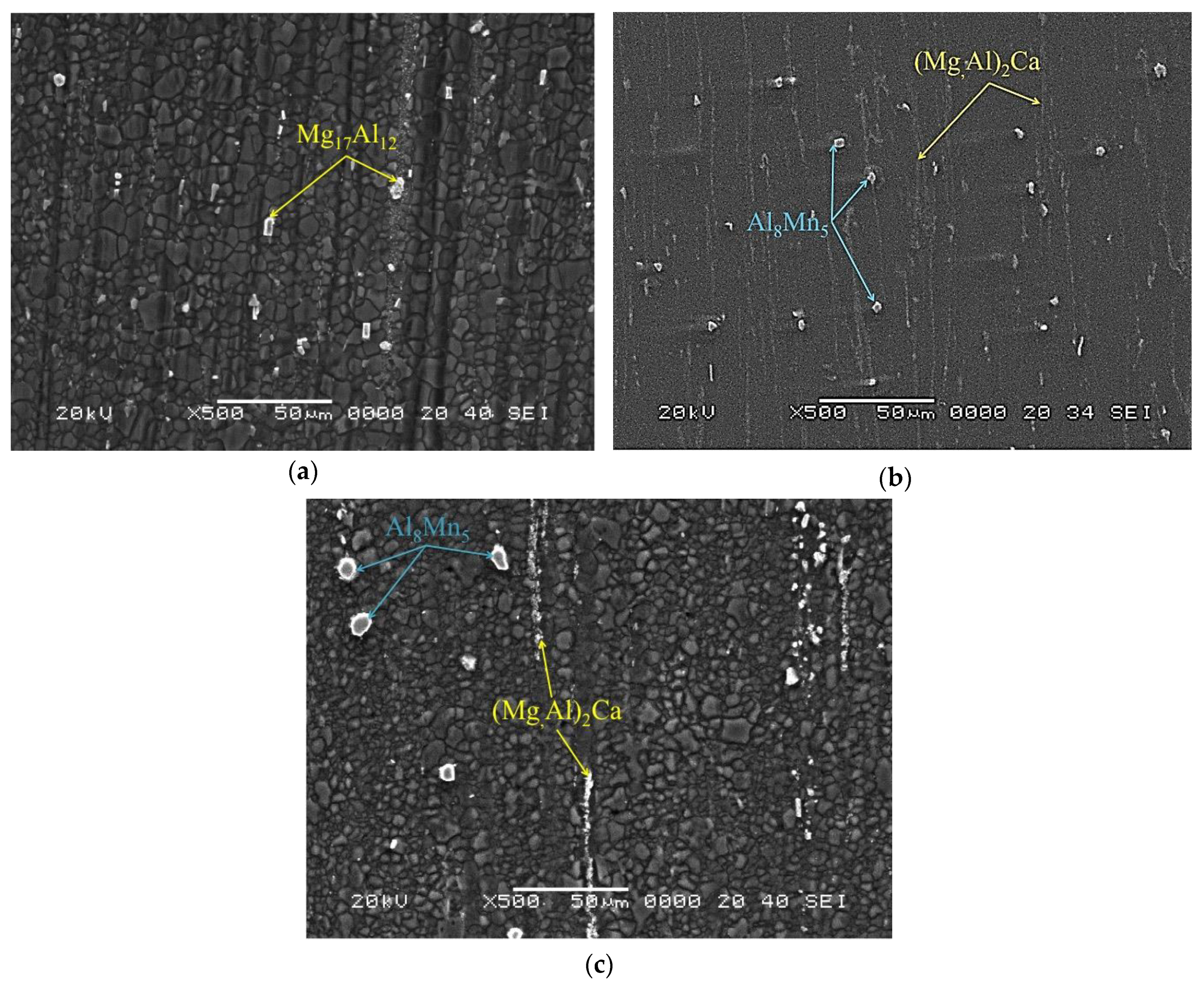
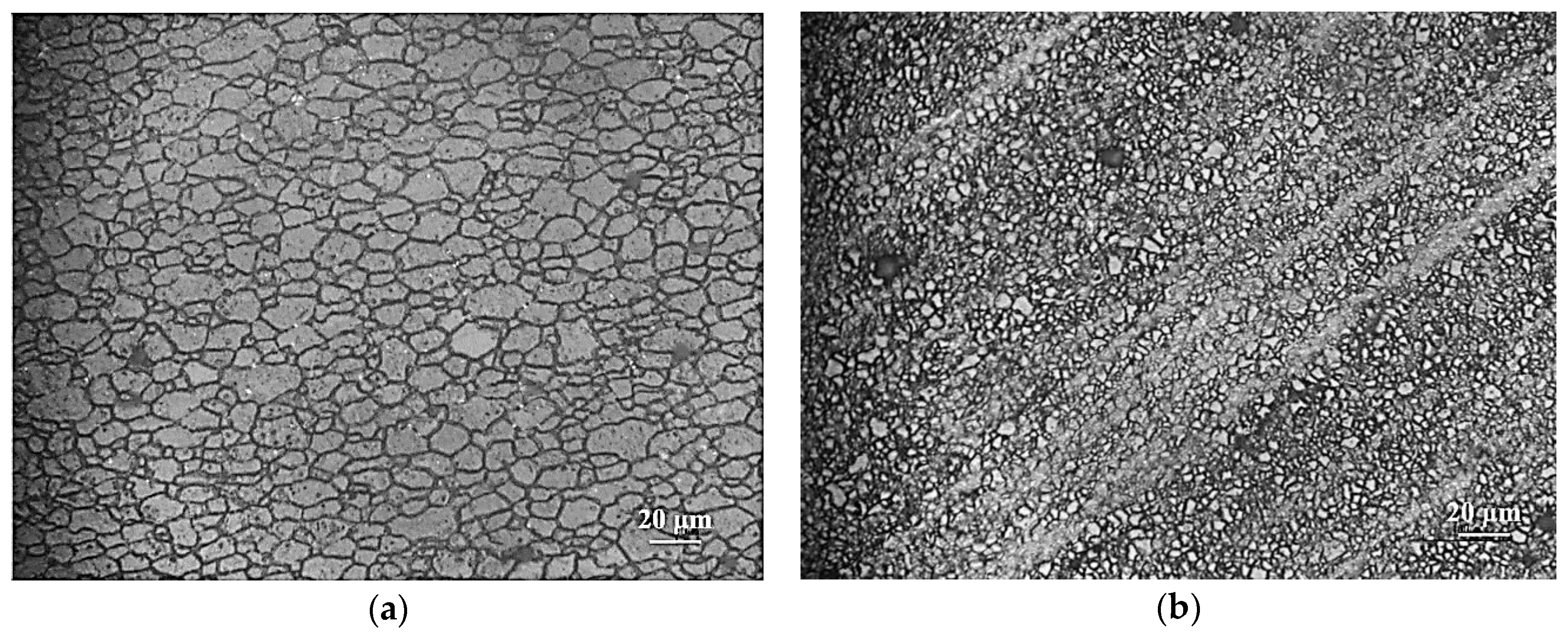
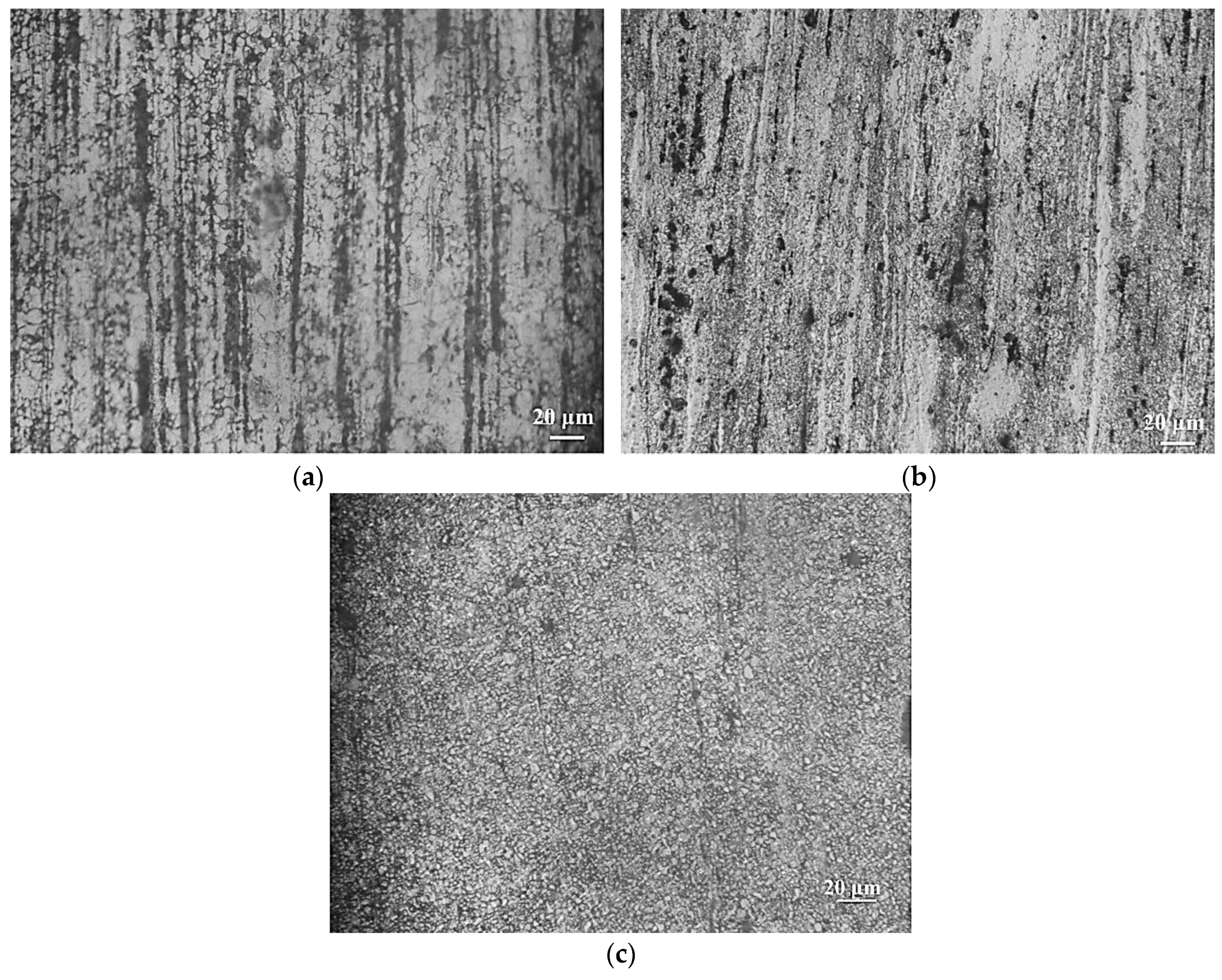
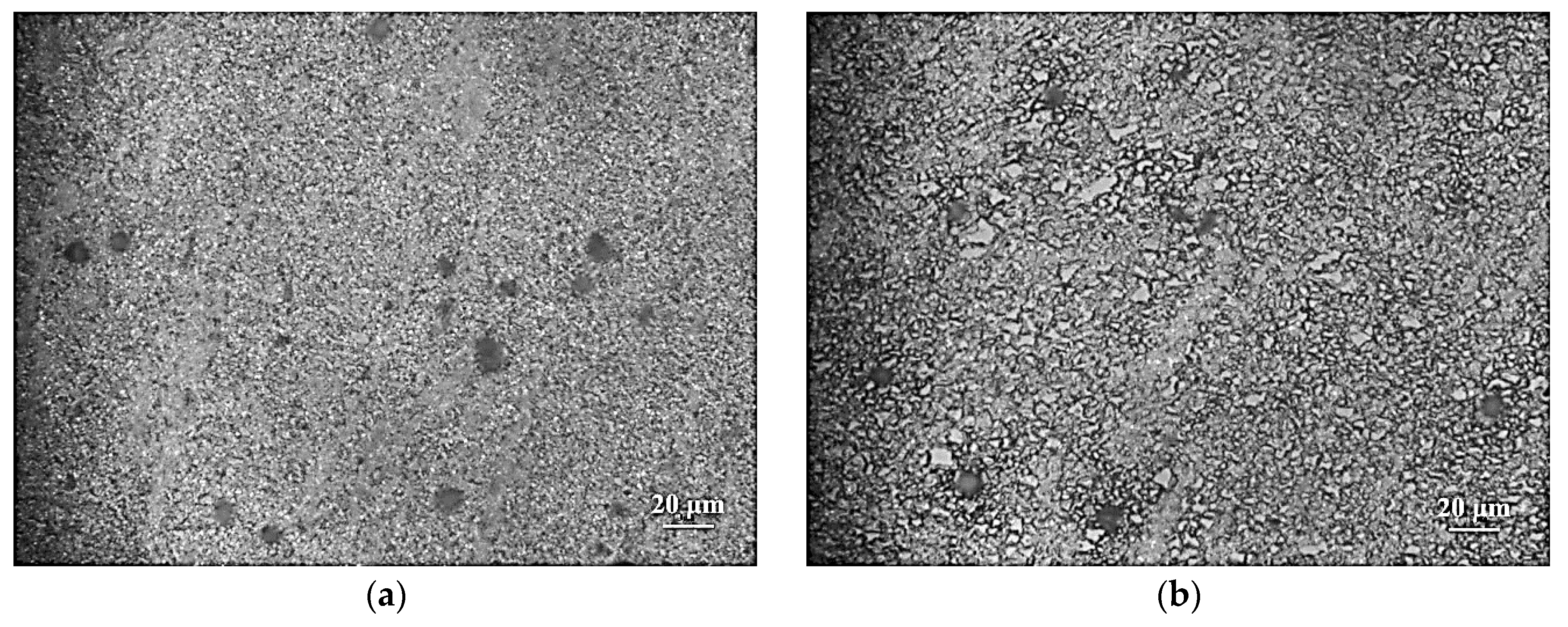
3.1. Initial Microstructure of the Composites

The starting microstructures of AZ31-1.5NAl, AZ31-1Ca-1.5NAl, and AZ31-2Ca-1.5NAl composites are shown in Figure 1a–c. Nano-alumina particles are uniformly distributed in the microstructure of all the three composites. The scanning electron micrographs (SEM images) in Figure 2a–c show the microstructure of AZ31-1.5NAl, AZ31-1.5NAl-1Ca, and AZ31-1.5NAl-2Ca composites. In Ca-containing composites, (Mg,Al)2Ca intermetallic phase particles are present and their volume fraction is increased with an increase in the Ca content. Also, a small amount of undissolved Al8Mn5 phase is present [12] and nano-alumina are drawn along bands in the extrusion direction. The average grain diameter in the base composite is about 7 μm, which is reduced to 2–3 μm range by addition of Ca and the grain size is more uniform in the case of 2% Ca-containing composite. The starting rod had a texture which may be described in terms of <10 1 ¯ 0> along the extrusion direction [13]. In the base composite, the texture is about 2–3 times the random while by the addition of 1% Ca, the texture intensity increases to 4–5 times the random. Details of the microstructural features for the composites are compared in Table 1. By the addition of calcium to the composite, the particle content has increased, the grain size is refined, and the texture intensity has increased.

3.2. Processing Maps for Hot Working

The hot deformation behavior of the three composites is analyzed with the help of processing maps developed on the basis of flow stress at different temperatures and strain rates. The processing maps are presented below along with the interpretations for the various domains and comparison with a view to bring out the effect of Ca on the hot working behavior.

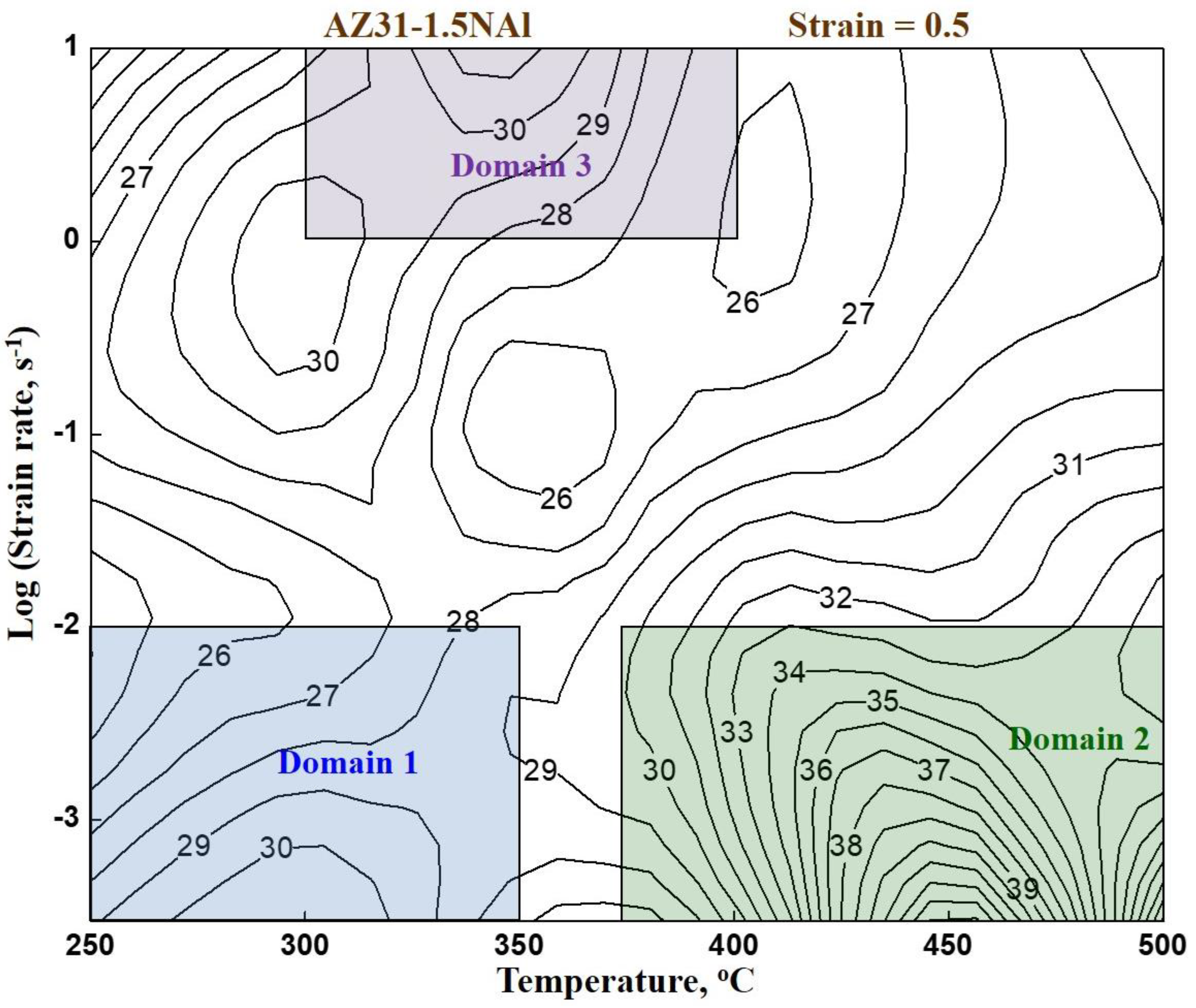
3.2.1. AZ31-1.5NAl Base Composite

The processing map for the base composite AZ31-1.5%NAl obtained at a true strain of 0.5 is shown in Figure 3, which exhibits three domains in the temperature and strain rate ranges given below:
(1) 250–350 °C and 0.0003–0.01 s−1 with a peak efficiency of 30% at 300 °C/0.0003 s−1.
(2) 375–500 °C and 0.0003–0.01 s−1 with a peak efficiency of 43% at 450 °C/0.0003 s−1.
(3) 300–400 °C and 1–10 s−1 with a peak efficiency of 31% at 350 °C/10 s−1.
In an earlier publication [13], detailed investigation of microstructures, kinetic parameters, elongation, and fracture features were presented and the above domains have been interpreted to represent DRX occurring with different slip and recovery mechanisms in the various temperature and strain rate ranges. The results are summarized in Table 1 and are briefly described below:
In Domain 1, basal slip {0001} <11 2 ¯ 0> occurs along with some prismatic slip {10 1 ¯ 0} <11 2 ¯ 0> and the recovery mechanism is climb of edge dislocations controlled by lattice self-diffusion.
In Domain 2, second-order pyramidal slip {11 2 ¯ 2} <11 2 ¯ 3> occurs since the temperature range is higher and the associated recovery mechanism to nucleate DRX is cross-slip in view of availability of a large number of intersecting slip systems and high stacking fault energy. The DRX microstructure promotes grain boundary sliding resulting in wedge cracking at higher strains.
In Domain 3, basal slip {0001} <11 2 ¯ 0> occurs along with some prismatic slip {10 1 ¯ 0} <11 2 ¯ 0>. However, because of higher strain rates, shorter times are available for recovery. Recovery therefore occurs by climb of edge dislocations controlled by grain boundary self-diffusion.

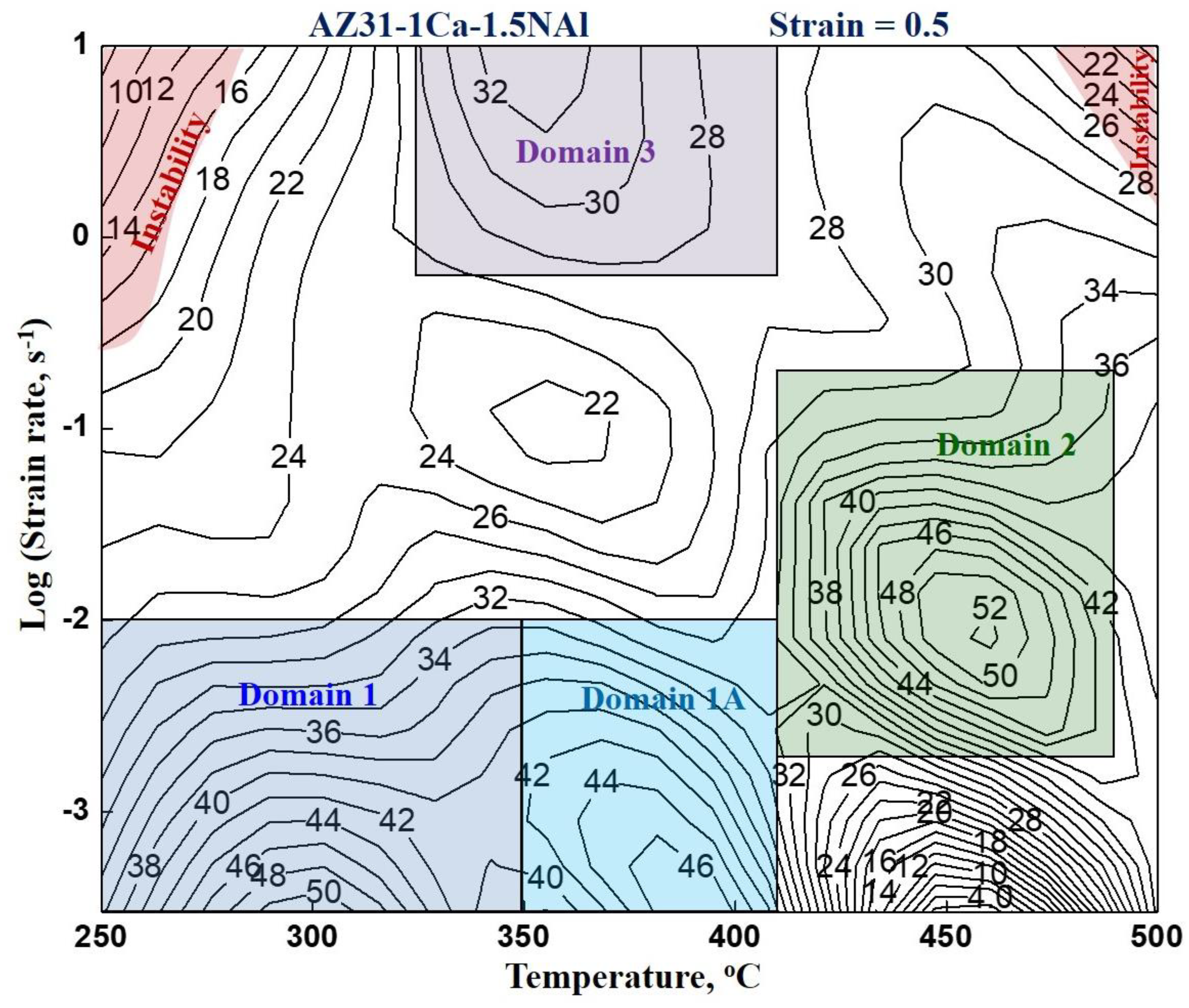
3.2.2. AZ31-1Ca-1.5NAl Composite

The processing map for AZ31-1Ca-1.5NAl composite is shown in Figure 4, which exhibits four domains in the temperature and strain rate ranges given below:
(1) 250–350 °C and 0.0003–0.01 s−1 with a peak efficiency of 50% at 300 °C/0.0003 s−1.
(1A) 350–410 °C and 0.0003–0.01 s−1 with a peak efficiency of 46% at 400 °C/0.0003 s−1.
(2) 410–490 °C and 0.002–0.2 s−1 with a peak efficiency of 52% at 450 °C/0.01 s−1.
(3) 325–410 °C and 0.6–10 s−1 with a peak efficiency of 33% at 350 °C/10 s−1.
All the above domains represent DRX and the slip systems and recovery mechanisms nucleating DRX have been identified on the basis of microstructure and kinetic parameters and the detailed results are discussed in an earlier publication [12]. Basically, the mechanisms are similar to those in Domains (1), (2), and (3) of the base composite AZ31-1.5NAl except two changes when 1% Ca is added: (a) Domain 1 is split into (1) and (1A), and (b) wedge cracking in Domain 2 is mitigated. Firstly, in the map for the base composite, basal slip and prismatic slip are occurring together in Domain 1, while with 1% Ca addition, basal slip occurs in Domain 1 and prismatic slip occurs at higher temperatures in Domain 1A. This is due to the higher back stress caused by the Ca-containing intermetallic particles requiring higher temperatures for the occurrence of prismatic slip. Secondly, wedge cracking is eliminated when Ca is added since the Ca-containing intermetallic particles pin down the grain boundaries from sliding and avoid the formation of cracks at the triple junctions.

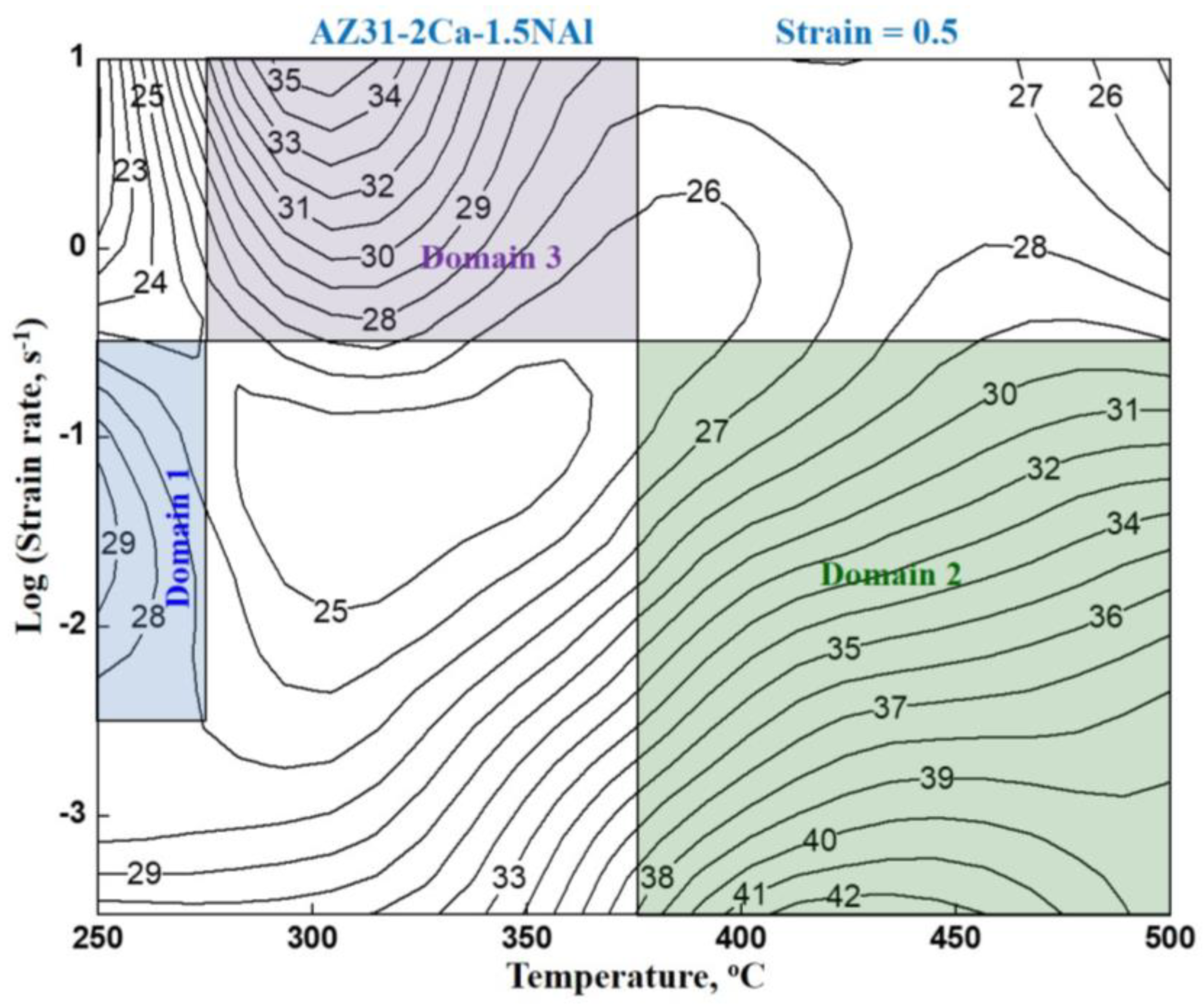
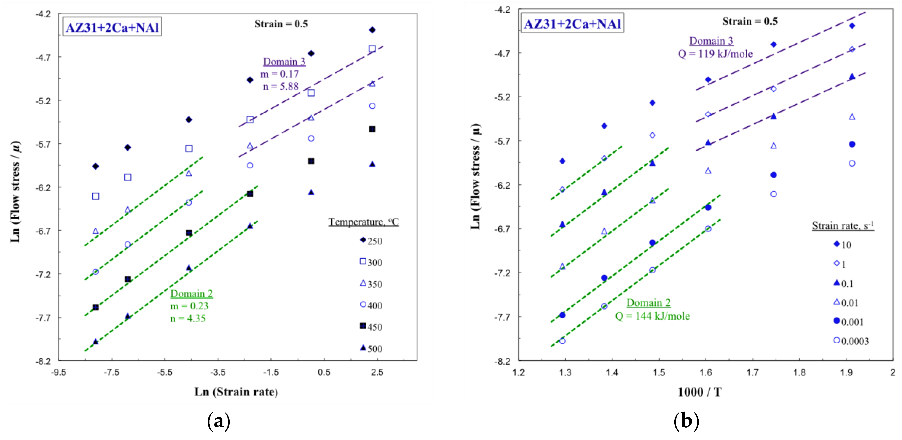
3.2.3. AZ31-2Ca-1.5NAl Composite

The processing map for AZ31-2Ca-1.5NAl composite is shown in Figure 5, which exhibits three domains in the temperature and strain rate ranges given below:
(1) 250–275 °C and 0.003–0.3 s−1 with a peak efficiency of 29% at 250 °C/0.03 s−1.
(2) 375–500 °C and 0.0003–0.3 s−1 with a peak efficiency of 42% at 425 °C/0.0003 s−1.
(3) 275–375 °C and 0.3–10 s−1 with a peak efficiency of 35% at 300 °C/10 s−1.
Unlike Domain 1 in the map for the base composite and that with 1% Ca, Domain 1 in the 2% Ca composite occurs over a very narrow range and at higher strain rates with a peak efficiency lower than 30%. The microstructure of the specimen deformed at 250 °C and 0.1 s−1 in the domain is shown in Figure 6a, which reveals that recrystallization has occurred. However, the grain size is very fine, suggesting that dynamic recovery has occurred during deformation, followed by recrystallization during cooling from the test temperature. Thus, Domain 1 represents dynamic recovery. Dynamic recrystallization similar to that in Domain 1 in the map for the base composite and that with 1% Ca has not occurred in the composite with 2% Ca. This may be attributed to the presence of larger back stress in the 2% Ca composite caused by the larger volume fraction of Ca-containing intermetallic phase. This large back stress slows down the rate of dynamic recovery by climb, which is not sufficient for nucleating DRX. It may be recalled that in 1% Ca composite, it is the back stress that has split the DRX domain into (1) and (1A) and with increasing Ca to 2%, the DRX does not occur within the temperature and strain rate ranges corresponding to Domain 1 of other composites.
Domain 2 is similar to that in the map for the base composite and that with 1% Ca but occurs in wider temperature and strain rate ranges. The microstructure of the specimen deformed at 400 °C and 0.0003 s−1 is shown in Figure 7a, which reveals that DRX has occurred. Kinetic analysis of the temperature and strain rate dependence of flow stress in this domain has been conducted using Equation (3) and a plot of normalized flow stress with strain rate at different temperatures is shown in Figure 8a. The stress exponent is estimated to be 4.3. Arrhenius plot showing normalized flow stress with inverse of absolute temperature is shown in Figure 8b and the apparent activation energy has been estimated to be 144 kJ/mole, which is in a similar range estimated in the base composite and 1% Ca-containing composite (Table 1). Because this is a higher temperature domain, second-order pyramidal slip {11 2 ¯ 2} <11 2 ¯ 3> occurs and the associated recovery mechanism is cross-slip since a large number of slip systems will be available and the stacking fault energy is high (173 mJ/m−2) [22]. The tensile ductility measured at 400 °C/0.0003 s−1 is 49% and the SEM fractograph of the fracture surface is shown in Figure 9a, which reveals dimple features typical of ductile fracture. Thus, increasing calcium content has expanded this domain and also enhanced the tensile ductility.
Domain 3 in all the three composites occurs at lower temperatures and higher strain rates. In the composite with 2% Ca, this domain has become wider than the base composite and the one with 1% Ca. The microstructure obtained on the specimen deformed at 300 °C/10 s−1 is fine-grained (Figure 7b), which reveals that DRX occurs in this domain. Kinetic analysis done on the temperature and strain rate dependence of flow stress in this domain is shown in Figure 8a,b, which give a stress exponent of 5.88 and the apparent activation energy of 119 kJ/mole. These values are very similar in all the three composites (Table 1). In the temperature range for this domain (275–375 °C), basal slip {0001} <11 2 ¯ 0> occurs along with some prismatic slip {10 1 ¯ 0} <11 2 ¯ 0>. The major recovery mechanism will be climb of edge dislocations. Since the strain rates are high (>1 s−1), climb will be controlled by grain boundary self-diffusion that is highly favored in the composite due to very fine grain size. The apparent activation energy of 119 kJ/mole is in close agreement with that required for grain boundary self-diffusion in Mg (95 kJ/mole) [23], taking into account the role of high back stress. The tensile ductility measured within the range of parameters in the domain (300 °C/2.3 s−1) is 42%, which indicates that the workability is good. SEM fractograph of the fracture surface is shown in Figure 9b, which reveals dimple features typical of ductile fracture. This domain assumes importance for processing the composite since the high strain rates are conducive for manufacturing. The resulting fine-grained structure is an added advantage for improved product properties. Addition of 2% Ca is helpful in enhancing the workability of the composite, particularly at higher strain rates, which are useful in designing commercial processes for component manufacture.
The region that separates Domains 1, 2, and 3 occurring in the temperature range 275–375 °C and strain rate range 0.003–0.3 s−1 with lowest efficiency of 25% is similar to a saddle configuration and may be termed as a bifurcation in chaotic dynamic systems terminology [17] where probability plays a role. In this region, when the dissipative energy reaches a peak and is akin to the top of a hill [16], hot working at any combination of temperature/strain rate parameters within this region will give rise to microstructural instability. The resulting microstructure will not be reproducible since it will be probability-related. An uncertain combination of microstructure depending on the three mechanisms in the surrounding domains will occur and a simple manifestation will be a mixture of fine and coarse grains [19] with uneven distribution of other microconstituents. The microstructure of the specimen deformed at 350 °C/0.1 s−1 is shown in Figure 6b, which reveals patches of large grains within a fine-grained microstructure. Processing in the bifurcation region is not recommended since microstructural control will be difficult and the component microstructure will be not reproducible.
The results of the occurrence of domains in the processing maps of all the three composites are as anticipated. As the solid solubility of Ca is low in Mg (only 1.34 wt.% at eutectic temperature of 517 °C) [24], the stacking fault energy (and the cross-slip on pyramidal planes) is not significantly affected. So, the effect of Ca on DRX mechanisms is essentially through the formation of intermetallic phases and particles. As the volume fraction of intermetallic phases increased with the increase in Ca%, the presence of large back stress slowed down the rate of dynamic recovery by climb, and therefore the DRX nucleation. As a result, Domain 1 (DRX) that occurred in base and 1% Ca composites was replaced by a narrow domain at lower temperatures and higher strain rates in 2% Ca composite where only dynamic recovery has occurred. The presence of Domain 2 at similar deformation conditions ranges in all the three composites is as expected, attributing to the involvement of second-order pyramidal slip. The Domain 2 in 2% Ca-containing composite is wide due to the higher number of second phase particles that act as obstacles to dislocation movement, which in turn increases the dislocation density and thereby the rate of DRX nucleation. Domain 3 in 2% Ca composite is shifted toward lower temperatures compared to base and 1% Ca composite. The high-volume content of particles in the 2% Ca composite retards the rate of grain boundary migration by pinning the boundaries resulting to the refined DRX grain size. The refinement of grain size promotes the grain boundary self-diffusion and therefore the climb of edge dislocations has become relatively easier at lower temperatures than in the base and 1 wt.% Ca composites.

4. Conclusions

The effect of 1% and 2% Ca on the hot working behavior of AZ31-1.5 vol.% nano-alumina composite produced by disintegrated melt deposition (DMD) processing has been investigated by developing processing maps in the temperature range 250–500 °C and strain rate 0.0003–10 s−1. The following conclusions are drawn from this investigation:
  • The addition of calcium to AZ31-1.5NAl composite refines the grain size and increases the <10 1 ¯ 0> texture in the rod.
  • All the three nanocomposites exhibit three DRX domains in the approximate temperature–strain rate ranges of (1) 250–300 °C/0.0003 –0.01 s−1, (2) 400–500 °C/0.0003–0.03 s−1, and (3) 300–400 °C/1–10 s−1.
  • With 1% Ca addition to AZ31 nano-alumina composite, Domain 1 is split into two: in one part, basal slip dominates, and prismatic slip dominates in the other part, with climb as the recovery mechanism. Domain 2 moves to higher strain rates and Domain 3 has become wider.
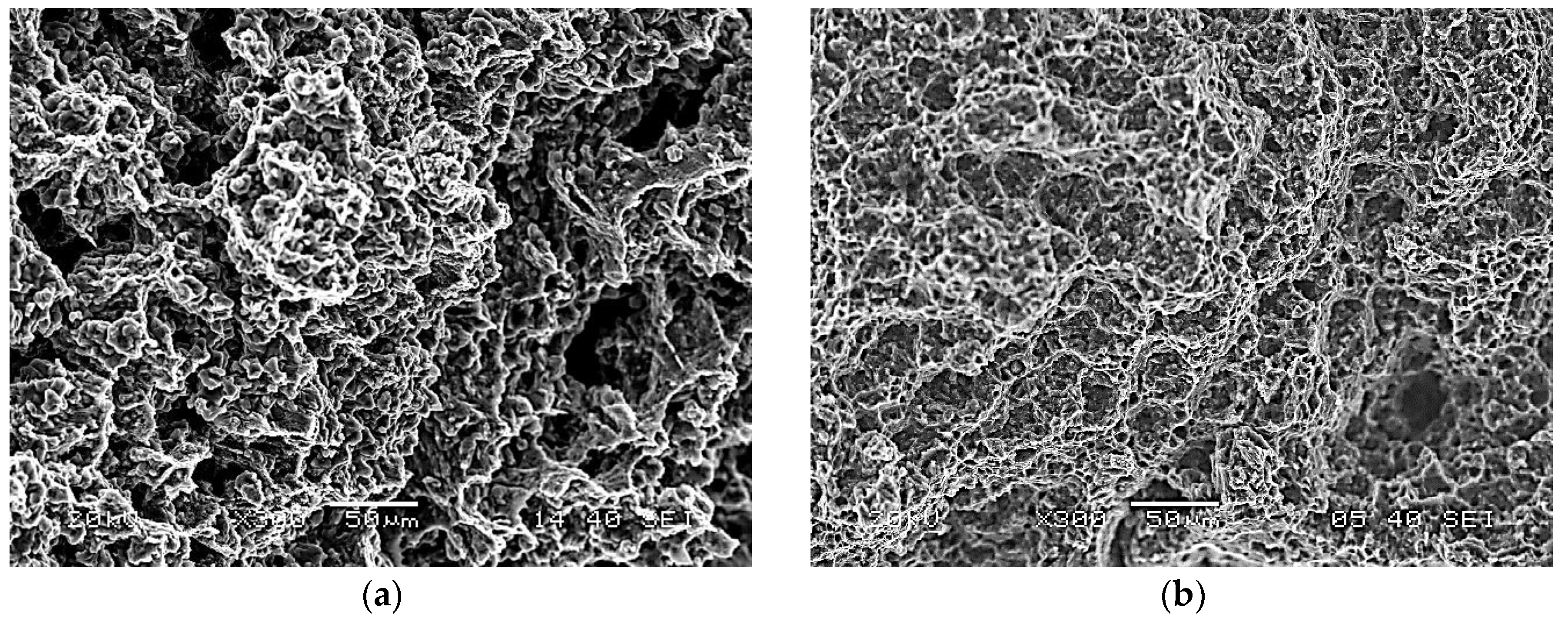
  • Addition of Ca avoids wedge cracking that occurs in AZ31-1.5NAl composite at higher temperatures and lower strain rates (Domain 2). This is because the Ca-containing intermetallic particles pin down the grain boundary and prevent sliding, thereby avoiding formation of wedge cracks at grain boundary triple junctions.
  • Addition of 1% Ca to AZ31-1.5NAl composite widens all the three workability windows and enhances the hot workability. This composition may be considered to be optimum from hot workability viewpoint.
  • Increase of Ca addition to 2% prevents DRX at lower temperatures and strain rates (Domain 1) of base composite and causes only dynamic recovery. This is due to high back stress, caused by Ca-containing particles, that slows down recovery by climb and reducing rate of DRX nucleation.
  • Domain 3 occurring at lower temperatures and higher strain rates is common to all the three composites and is widened by Ca addition. DRX in this domain occurs by basal + prismatic slip along with recovery via climb controlled by grain boundary self-diffusion due to very fine grain size in the composite.
  • All the three composites may be processed under conditions corresponding to Domain 3 since the strain rates are high enough to ensure productivity, and the grain size resulting in the component will be fine, giving superior product properties.

Author Contributions

K.P.R. and C.D. have performed the analysis of the data, generating processing map, kinetic analysis, and writing the paper; K.S. has performed the experimental work, generating the results and microstructural work; Y.V.R.K.P. has contributed on the aspects related to the processing map and writing the paper; M.G. has developed and provided the DMD-processed composites.

Funding

The work described in this paper was supported by a grant from the Research Grants Council (RGC Ref. No. 114811) of the Hong Kong Special Administrative Region, China, and a Strategic Research Grant (Project No. 7008098) from the City University of Hong Kong.

Conflicts of Interest

The authors declare no conflict of interest.

References

  1. Kainer, K.U.; Dieringa, H.; Dietzel, W.; Hort, N.; Blawert, C. The use of magnesium alloys: Past, present and future. In Magnesium Technology in Global Age; Pekguleryuz, M.O., Mackenzie, L.W.F., Eds.; Canadian Institute of Mining, Metallurgy and Petroleum: Montreal, QC, Canada, 2006; pp. 3–19. [Google Scholar]
  2. Rao, K.P.; Prasad, Y.V.R.K.; Dharmendra, C.; Suresh, K.; Hort, N.; Dieringa, H. Review on hot working behavior and strength of calcium-containing magnesium alloys. Adv. Eng. Mater. 2018. [Google Scholar] [CrossRef]
  3. Hassan, S.F.; Gupta, M. Development of nano-Y2O3 containing magnesium nano-composites using solidification processing. J. Alloys Compd. 2007, 429, 176–183. [Google Scholar] [CrossRef]
  4. Habibnejad-Korayem, M.; Mahmudi, R.; Poole, W.J. Enhanced properties of Mg-based nano-composites reinforced with Al2O3 nanoparticles. Mater. Sci. Eng. A 2009, 519, 198–203. [Google Scholar] [CrossRef]
  5. Paramsothy, M.; Hassan, S.F.; Srikanth, N.; Gupta, M. Enhancing tensile/compressive response of magnesium alloy AZ31 by integrating with Al2O3 nanoparticles. Mater. Sci. Eng. A 2009, 527, 162–168. [Google Scholar] [CrossRef]
  6. Ezatpour, H.R.; Chaichi, A.; Sajjadi, S.A. The effect of Al2O3-nanoparticles as the reinforcement additive on the hot deformation behavior of 7075 aluminum alloy. Mater. Des. 2015, 88, 1049–1056. [Google Scholar] [CrossRef]
  7. Liu, W.; Wang, X.; Hu, X.; Wu, K.; Zheng, M. Effects of hot rolling on microstructure, macrotexture and mechanical properties of pre-extruded AZ31/SiC nanocomposite sheets. Mater. Sci. Eng. A 2017, 683, 15–23. [Google Scholar] [CrossRef]
  8. Wang, T.; Nie, K.; Deng, K.; Liang, W. Analysis of hot deformation behavior and microstructure evolution of as-cast SiC nanoparticles reinforced magnesium matrix composite. J. Mater. Res. 2016, 31, 3437–3447. [Google Scholar] [CrossRef]
  9. Nguyen, Q.B.; Gupta, M. Improving compressive strength and oxidation resistance of AZ31B magnesium alloy by addition of nano-Al2O3 particulates and Ca. J. Compos. Mater. 2010, 44, 883–896. [Google Scholar] [CrossRef]
  10. Nguyen, Q.B.; Gupta, M. Enhancing mechanical response of AZ31B using Cu+nano-Al2O3 addition. Mater. Sci. Eng. A 2010, 527, 1411–1416. [Google Scholar] [CrossRef]
  11. Paramsothy, M.; Chan, J.; Kwok, R.; Gupta, M. Enhanced mechanical response of hybrid AZ31/AZ91 based on the addition of Si3N4 nanoparticles. Mater. Sci. Eng. A 2011, 528, 6545–6551. [Google Scholar] [CrossRef]
  12. Suresh, K.; Dharmendra, C.; Rao, K.P.; Prasad, Y.V.R.K.; Gupta, M. Processing Map of AZ31-1Ca-1.5vol.% Nano-Alumina Composite for Hot Working. Mater. Manuf. Process. 2015, 30, 1161–1167. [Google Scholar] [CrossRef]
  13. Zhong, T.; Rao, K.P.; Prasad, Y.V.R.K.; Zhao, F.; Gupta, M. Hot deformation mechanisms, microstructure and texture evolution in extruded AZ31-Nano Alumina composite. Mater. Sci. Eng. A 2014, 589, 41–49. [Google Scholar] [CrossRef]
  14. Prasad, Y.V.R.K.; Rao, K.P.; Sasidhara, S. Hot Working Guide: A Compendium of Processing Maps, 2nd ed.; ASM International: Materials Park, OH, USA, 2015; ISBN 978-1-62708-091-0. [Google Scholar]
  15. Prasad, Y.V.R.K.; Seshacharyulu, T. Modelling of hot deformation for microstructural control. Int. Mater. Rev. 1998, 43, 243–258. [Google Scholar] [CrossRef]
  16. Prasad, Y.V.R.K. Processing maps: A status report. J. Mater. Eng. Perform. 2003, 12, 638–645. [Google Scholar] [CrossRef]
  17. Hilborn, R.C. Chaos and Non-Linear Dynamics; Oxford University Press: Oxford, UK, 1994. [Google Scholar]
  18. Ziegler, H. Some extremum principles in irreversible thermodynamics with applications to continuum mechanics. In Progress in Solid Mechanics; Sneddon, I.N., Hill, R., Eds.; John Wiley: New York, NY, USA, 1965; Volume 4, pp. 91–193. [Google Scholar]
  19. Prasad, Y.V.R.K.; Rao, K.P. Hot deformation mechanisms and microstructural control in high temperature extruded AZ31 magnesium alloy. Adv. Eng. Mater. 2007, 9, 558–565. [Google Scholar] [CrossRef]
  20. Jonas, J.J.; Sellars, C.M.; Tegart, W.J.M. Strength and structure under hot working conditions. Metall. Rev. 1969, 14, 1–24. [Google Scholar]
  21. Prasad, Y.V.R.K.; Rao, K.P. Processing maps and rate controlling mechanisms of hot deformation of electrolytic tough pitch copper in the temperature range 300–950 °C. Mater. Sci. Eng. A 2005, 391, 141–150. [Google Scholar] [CrossRef]
  22. Morris, J.R.; Scharff, J.; Ho, K.M.; Turner, D.E.; Ye, Y.Y.; Yoo, M.H. Prediction of a {1122} hcp stacking fault using a modified generalized stacking-fault calculation. Philos. Mag. A 1997, 76, 1065–1077. [Google Scholar] [CrossRef]
  23. Frost, H.J.; Ashby, M.F. Deformation-Mechanism Maps; Pergamon Press: Oxford, UK, 1982; p. 44. [Google Scholar]
  24. Alloy Phase Diagrams. ASM Handbook; ASM International: Materials Park, OH, USA, 1992; Volume 3, p. 556. [Google Scholar]
Figure 1. Microstructures of starting material prepared by DMD processing: (a) AZ31-1.5NAl composite, (b) AZ31-1Ca-1.5NAl composite, and (c) AZ31-2Ca-1.5NAl composite. The extrusion direction is vertical.
Metals 08 00699 g001
Figure 2. SEM images of initial composites produced by DMD processing and extrusion: (a) AZ31-1.5NAl, (b) AZ31-1Ca-1.5NAl, and (c) AZ31-2Ca-1.5NAl. The extrusion direction is vertical.
Metals 08 00699 g002
Figure 3. Processing map for DMD-processed AZ31-1.5NAl composite at a strain of 0.5. The numbers associated with the contours indicate efficiency of power dissipation in percent. Reproduced with permission from [13], Elsevier, 2014.
Metals 08 00699 g003
Figure 4. Processing map for DMD-processed AZ31-1Ca-1.5NAl composite at a strain of 0.5. The numbers associated with the contours indicate efficiency of power dissipation in percent. Reproduced with permission from [12], Taylor and Francis, 2015
Metals 08 00699 g004
Figure 5. Processing map for hot working of DMD-processed AZ31-2Ca-1.5NAl composite obtained at a true strain of 0.5. The numbers associated with the contours indicate efficiency of power dissipation in percent.
Metals 08 00699 g005
Figure 6. Microstructures of AZ31-2Ca-1.5NAl composite deformed at (a) 250 °C/0.1 s−1 (Domain 1) and (b) 350 °C/0.1 s−1 (bifurcation region).
Metals 08 00699 g006
Figure 7. Microstructures of AZ31-2Ca-1.5NAl composite deformed at (a) 400 °C/0.0003 s−1 (Domain 2) and (b) 300 °C/10 s−1 (Domain 3).
Metals 08 00699 g007
Figure 8. (a) Variation of normalized flow stress with strain rate on natural logarithmic scale, and (b) Arrhenius plot of normalized flow stress with inverse of absolute temperature. The apparent activation parameters n and Q are estimated with data relevant to various domains of processing map for the AZ31-2Ca-1.5NAl composite.
Metals 08 00699 g008
Figure 9. SEM fractographs of the fracture surface of AZ31-2Ca-1.5NAl composite tested in tension at 400 °C/0.0003 s−1 (Domain 2) and (b) 350 °C/2.3 s−1 (Domain 3).
Metals 08 00699 g009
Table 1. Details of microstructural parameters (1–3), (4) temperature–strain rate ranges for domains, (5) peak efficiency (η) conditions, (6) apparent activation energy (Qapp) and (7) tensile elongation, and (8) proposed mechanisms in the various domains of processing maps for DMD-processed AZ31-1.5 NAl, AZ31-1Ca-1.5NAl, and AZ31-2Ca-1.5NAl composites.
Parameter AZ31-1.5 NAl [13]AZ31-1Ca-1.5NAl [12]AZ31-2Ca-1.5NAl (Current Research)
Initial grain size, μm(1)72–32–3
Initial texture(2)2–3 R4–5 R
Phases in the microstructure(3)Nano-alumina;
Al8Mn5
Nano-alumina;
(Mg,Al)2Ca; Al8Mn5
Nano-alumina;
(Mg,Al)2Ca; Al8Mn5
Domain 1(4)250–350 °C
0.0003–0.01 s−1
250–350 °C
0.0003–0.01 s−1
250– 75 °C
0.003–0.3 s−1
(5)300 °C/0.0003 s−1;
peak η: 30%
300 °C/0.0003 s−1;
peak η: 50%
250 °C/0.03 s−1
peak η: 29%
(6)116 kJ/mole96 kJ/mole
(7)30%
(8)DRX: Basal slip + climb by Lattice self-diffusionDRX: Basal slip + climb by lattice self-diffusionDynamic recovery
Domain 1A(4)350–410 °C
0.0003–0.01 s−1
(5)400 °C/0.0003 s−1;
peak η: 46%
(8)DRX: Prismatic slip + climb by lattice self-diffusion
Domain 2(4)375–500 °C
0.0003–0.01 s−1
410–490 °C
0.002–0.2 s−1
375–500 °C
0.0003–0.3 s−1
(5)450 oC/0.0003 s−1;
peak η: 43%
450 °C/0.01 s−1;
peak η: 52%
425 °C/0.0003 s−1;
peak η: 42%
(6)152 kJ/mole276 kJ/mole144 kJ/mole
(7)42%24%49% (at 400 °C)
(8)DRX: Pyramidal slip + cross slipDRX: Pyramidal slip + cross slipDRX: Pyramidal slip + cross slip
Domain 3(4)300–400 °C
1–10 s−1
325–410 °C
0.6–10 s−1
275–375 °C
0.3–10 s−1
(5)350 °C /10 s−1;
peak η: 31%
350 °C/10 s−1;
peak η: 33%
300 °C/10 s−1;
peak η: 35%
(6)119 kJ/mole103 kJ/mole119 kJ/mole
(7)18% (at 3 s−1)42% (at 2.3 s−1)
(8)DRX: Basal slip + climb by grain boundary self-diffusionDRX: Basal slip + climb by grain boundary self-diffusionDRX: Basal slip + climb by grain boundary self-diffusion

